1. Introduction
An inductive wireless power transfer (WPT) system was considered for an electric vehicle (EV) or a plug-in hybrid vehicle (PHV) application. International standards for stationary (static) WPT systems are now being discussed by some international standards organizations [
1,
2,
3]. The stationary system frees drivers from having to plug into EVs or PHVs, thus providing safety, convenience, and easiness to drivers. However, for this technology to be more broadly adopted, the vehicle-side coils installed on EVs are required to be smaller, lighter, more efficient in power transfer, more tolerant of lateral misalignments, and a large air gap. Stationary WPT systems have been developed for ten years [
4,
5,
6,
7,
8,
9,
10].
However, even if stationary systems were introduced on the market, EVs would still have the following inevitable problems: A shorter mileage than internal-combustion-engine vehicles and a longer charging time than a fuel-filling time. In other words, stationary WPT systems will not decrease the charging time and will not increase the driving range. On the other hand, a dynamic WPT system is a solution to these problems, because the dynamic system is free from electric power charging similar to an electric train that feeds from power cables. Many types of dynamic WPT systems are proposed in a capacitive WPT system [
11], an inductive WPT system including coil structure [
12,
13,
14], connecting method and resonance topology [
15,
16], and feasibility [
17]. Moreover, while comprehensive research on inductive dynamic WPT systems is currently in progress, as seen in [
11] and [
17,
18,
19,
20,
21,
22,
23,
24,
25], these do not show compelling experimental data. To discuss and compare results, an index or performance mark is urgently required.
This paper describes a dynamic WPT system. First, the configuration of the dynamic system is detailed. The system has multiple solenoid coils connected in parallel in input side. The topology is based on the parallel-series (PS). Second, a theoretical analysis of a stationary and dynamic system based on PS topology was compared with a measured one on the basis of an equivalent transformer. Third, the 25-kW dynamic WPT system was constructed and tested to verify fundamental characteristics in a bench test. Fourth, a 20-m dynamic WPT charging lane was arranged, and it demonstrated its principles of operation using a real car. Finally, some performance indexes were proposed to compare dynamic WPT systems based on the experiments presented in this paper.
2. Experimental Setup
2.1. Circuit Configurations
Figure 1 shows the circuit configuration of the dynamic WPT system considered in this paper, the topology of which is based on the PS connected WPT system. A voltage-controlled power-factor-correction (PFC) circuit or AC/DC converter was connected to the single-phase 200 V, 50 Hz AC mains. The PFC configuration consists of a filter, a three-phase diode rectifier and a back converter. A full-bridge inverter was used for the ground-side coils. The filter was connected to the output of the inverter, which is designed for low-pass filter. The cutoff frequency of the filter is 100 kHz. The ground-side solenoid coils were connected in parallel with the primary resonant capacitors. Following this, the ground-side coils and resonant capacitors are referred to as ground-side coil sets. The vehicle-side solenoid coil was connected in series with the secondary resonant capacitor. A single-phase double current rectifier was used to achieve AC-to-DC power conversion at the receiving end [
26].
This topology, as shown in
Figure 1, has redundancy. Even if a ground side coil set is broken, the total dynamic WPT system can work without shutting down.
Table 1 summarizes the specifications of the dynamic WPT system in this experiment. The power capacity of these coils was rated at 25 kW. The nominal air-gap length was 170 mm. The inverter was operating at a high frequency of 85 kHz. H-shaped solenoid coils were chosen because of misalignment performance superiority to circular coils [
27]. The inverter was made with SiC mosfets. The vehicle-side coil was installed with a water-cooling system to minimize its size and heatsink.
2.2. WPT Coil Specifications
Table 2 summarizes the specifications of the H-shaped solenoid coils used in this experiment. These coils were designed based on rated values of
Table 1 and topology of
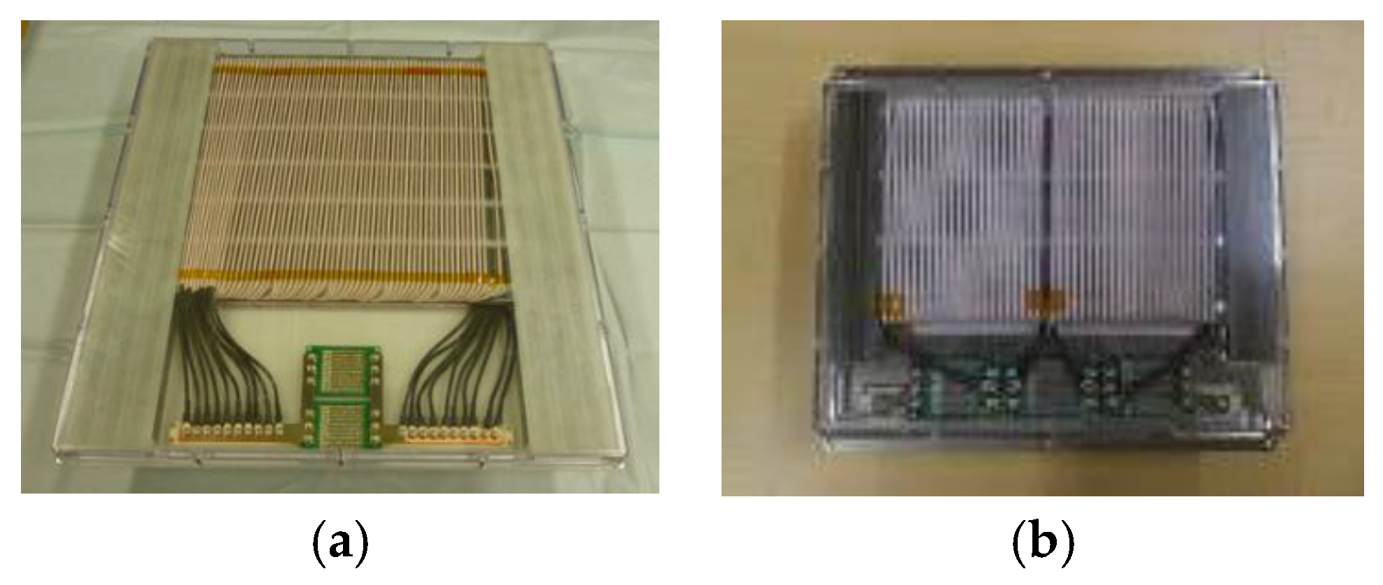
Figure 1. The ground-side coil dimensions were 620 mm × 600 mm × 40 mm and the vehicle-side coil were 430 mm × 374 mm × 38.5 mm. The core of both the ground-side and vehicle-side coils were made of ferrite. The windings were laced with 1200 bundles of 0.1-ϕ litz wires.
Figure 2 shows photographs of the WPT coils fabricated for this paper. The specifications are shown in
Table 2.
2.3. WPT Coil Parameters
Table 3 shows the experimental transformer parameters of the stationary WPT coils against aligned condition when the measured frequency was 85 kHz. The self-inductance of the ground-side coil
LN and vehicle-side coil
LS were 23.5 and 655 μH, respectively, while the subscript “
N” stands for the number of ground-side coils as shown in
Figure 1. Winding resistances
rN and
rS take into account skin and proximity effects and equivalent resistance for a ferrite core loss. The coupling coefficient
k between the ground-side coil and the vehicle-side coil at a 170-mm air-gap is 0.235.
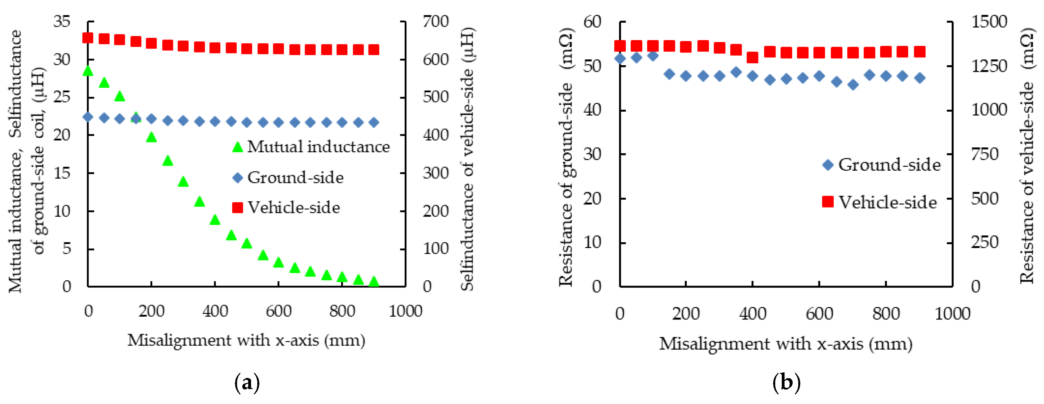
Figure 3 shows the experimental transformer parameters of the ground-side and vehicle-side coils against misalignment with the traveling direction of the vehicle (
x direction), where
N = 1. Variation of
LN and
LS in this experiment were 3.1% and 4.8%, respectively. Similarly,
rN and
rS were 8.4% and 2.9%. Mutual inductance between
LN and
LS at
x = 300 mm decreases to half of the original value (
x = 0 mm). Consequently, the mutual inductance is almost zero at
x = 900 mm.
3. Results
3.1. Transformer Analysis
In this subsection, equivalent circuits for two WPT systems were analyzed. One stationary and one dynamic. Both were based on PS topology, and calculated with an impedance matrix. Since the winding resistances and the equivalent ferrite-core-loss resistance are lower than the mutual and self-resistances at the fundamental frequency, these resistances were neglected from the following subsection.
3.1.1. Stationary System Analysis
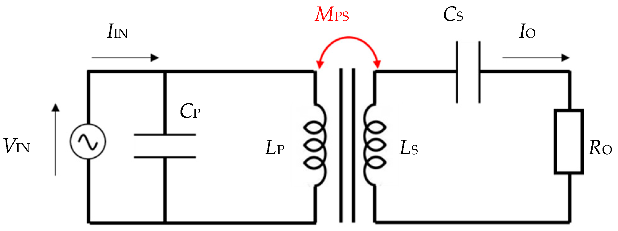
Figure 4 shows an equivalent circuit of the proposed stationary WPT system at a fundamental frequency. The input voltage and angular frequency are represented as
VIN and
ω, assuming a sinusoidal voltage. The self-inductances of the ground-side coil and the vehicle-side coil are defined as
LP and
LS, respectively. The mutual inductance between the ground-side and vehicle-side coils is defined as
MPS. The current and voltage directions are defined as shown in
Figure 4.
Here,
VIN and
VO are given as
To achieve effective power transfer, the input power factor approximates unity. The resonant capacitors defined
CP and
CS are determined as
From Equation (1), the output voltage VO increases linearly with the input voltage VIN. This is similar to ideal transformer behavior but different in coefficient. The output voltage also increases the mutual inductances or coupling factor, as shown in Equation (1). If the input and output voltage is approximately equivalent, the self-inductance value of the secondary (vehicle-side) coil needs to be much higher than that of the primary (ground-side) coil.
The input impedance of
Figure 4 is calculated by Equation (1) as
The input impedance is inversely proportional to the square of the coupling factor. When the vehicle-side coil is not above the ground-side coil, the input impedance of the WPT system increases to infinity. In other words, the proposed PS topology of the WPT system is stable and for the inverter not to over shoot at the input current, one does not need to install a high-response over current protection system at the inverter output line. Nevertheless, for safety reasons, an over current protection circuit was installed at the dc bus line to prevent unexpected situations.
3.1.2. Dynamic System Analysis
Figure 5 shows an equivalent circuit of the proposed dynamic WPT system at a fundamental frequency. For simplicity, the number of ground-side coils is limited to two. The definition is the same as in the previous subsection but different inductance values are used. The self-inductances of the first ground-side coil (coil 1), the second ground-side coil (coil 2) and the vehicle-side coil are defined as
L1,
L2 and
LS, respectively. The mutual inductances between coil 1 and coil 2, between coil 1 and the vehicle-side coil, and between coil 2 and the vehicle-side coil are defined as
M12,
M1S and
M2S, respectively.
Here,
VIN and
VO are given as
In this calculation, the self-inductances
L1 and
L2 have the same values as
L, because the ground-side coils have identical shapes and windings. To achieve effective power transfer, the input power factor approximates unity. The resonant capacitors defined
CP1,
CP2 and
CS are determined as
From Equation (4), the output voltage VO increases linearly with the input voltage VIN in a similar fashion as for the stationary system but, with a difference of a coupling factor term. The term is the sum of the coupling factors which the vehicle-side coil interlinks with. In this case, the two ground-side coils. From this equation, the design concept of the vehicle-side coil is the same as the stationary WPT system, and the vehicle-side coil is able to use both the stationary and dynamic coils.
The input impedance of
Figure 5 is calculated by Equation (4) as
The input impedance is also the same as for the stationary system. As discussed above, the dynamic WPT system is stable enough for the inverter not to over shoot at the input current.
3.2. Experimental Results
3.2.1. Stationary WPT System Results
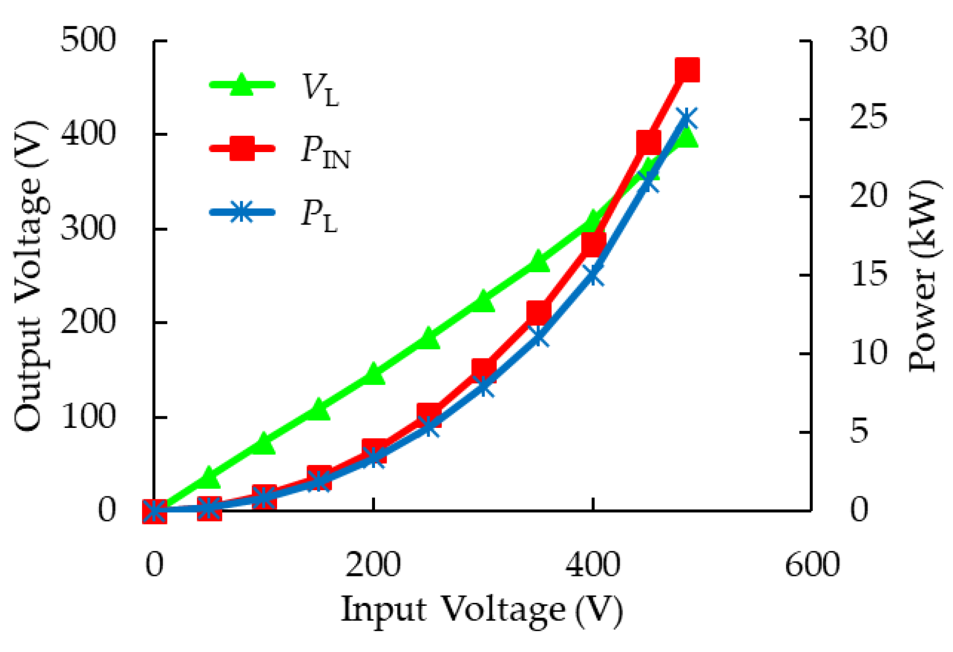
Figure 6 shows the experimental results with variation of input voltage
VIN. The circuit topology used was consistent with the topology detailed in
Figure 1, and the number of ground-side coils,
N, was one.
Table 4 lists the experimental circuit parameters. The position of the vehicle-side coil was kept at a nominal air-gap of 170 mm without misalignment. The operating frequency in the inverter was set to 85 kHz and was constant throughout the stationary experiment. The input voltage
VDC was proportional to the load voltage
VL, as shown in Equation (4). Load power
PL was 25 kW and efficiency was measured as 85.5% at
VIN = 485.6 V
DC in
Figure 1. The theoretical output voltage
V’
L calculated by Equation (4) using
Table 3 is 413.4 V. However, the experimental output voltage
VL was 398.4 V. The difference between the theoretical and experimental voltage may be explained by the decision not to take into account the winding resistances within the WPT coils and the misalignment of resonant capacitors in theoretical value.
3.2.2. Dynamic WPT System Test Bench Results
Figure 7 shows the photograph of the dynamic WPT system used in the following bench test experiments. The bench test system consisted of five ground-side coils with the same topology described in
Figure 1. The distance between each ground-side coil was 1200 mm. The velocity of the vehicle-side coil was 28 mm/s. The input voltage V
DC and frequency were controlled to be constant values of 240 V and 85 kHz, respectively. No other feedback loop was installed in this system.
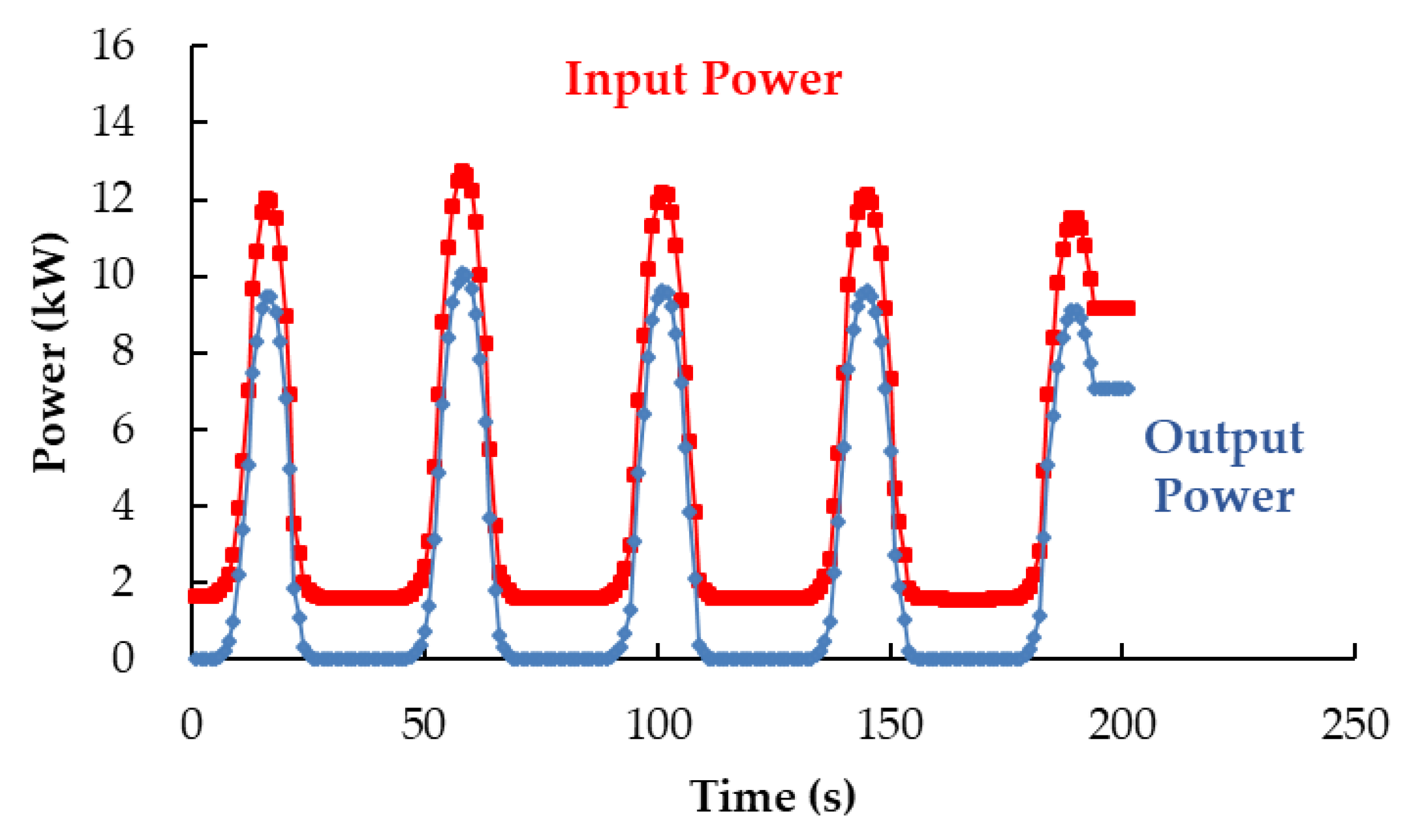
Figure 8 shows the input and output power characteristics over time for the moving vehicle–side coil. The parameters are listed in
Table 4. The peak values in
Figure 8 occurred when the vehicle-side coil and the ground-side coils where aligned. This phenomenon resulted in PS characteristics and connecting a resistive load. The energy transmitted to the vehicle (receiving energy) from one ground-side coil to the next ground-side coil was around 65 Wh under the conditions of this experiment. In addition, when the velocity of the vehicle-side coil was halved, the energy transmitted doubled. The power transfer from the experimental road to the vehicle was continuous for the duration of the test. The total energy conversion efficiency rate from the center of the first ground-side coil to that of the fifth one was 72.45%.
Figure 9 shows the input and output power characteristics over time for the moving vehicle–side coil. The parameters were the same as for
Figure 8 and
Table 4 except for the load condition. The load was a battery with a voltage
VL of 265 V. As can be seen from
Figure 9, there are times when the output power is equal to zero. This phenomenon results from PS characteristics and connecting a battery load. The transferred output voltage is also lower than the load voltage with a low coupling factor. The loss from the road power (i.e., ground-side coils), the filter and the inverter, was 1600 W in this system. The receiving energy of the vehicle from one ground-side coil to the next coil was around 28 Wh for this experiment’s conditions. The total energy conversion efficiency from the center of the first ground-side coil to the center of the fifth coil was 56.92%.
3.2.3. Dynamic WPT System Real-Car Test Results
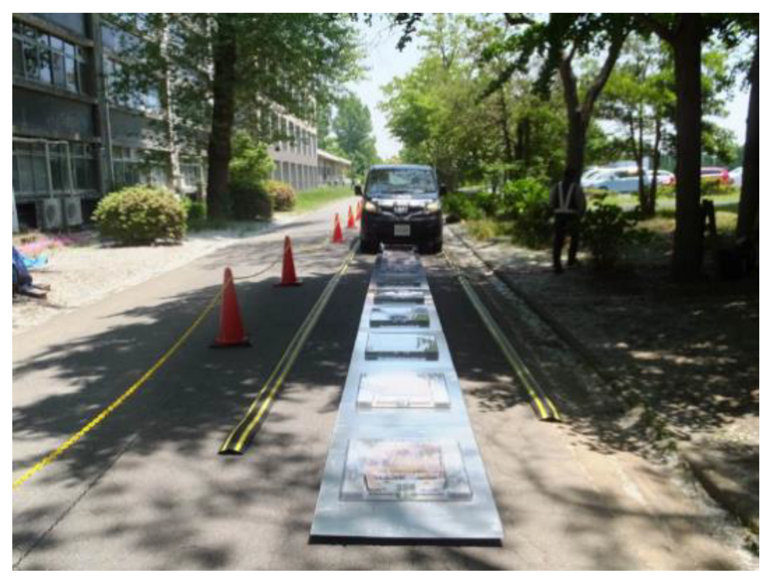
Figure 10 shows a photograph of the dynamic WPT system used in the following real-car test experiments. The circuit topology used was the same as in
Figure 1 with
N = 14. The circuit parameters are listed in
Table 5. The distance between each ground-side coil was 1200 mm. The total length of the WPT system was 16.8 m. The yellow and black lines placed on each side of the ground-side coils are guiding markers to help to driver to keep its trajectory straight. Al plates were also installed under the ground-side coils to reduce radiation. Note that the distance between the line from the filter to the ground-side coils was 23.5 m and the length of the air-gap between the WPT coils was measured at 170 mm when the vehicle-side coil was installed on the car. The output inverter voltage and current were controlled to not exceed 700 and 70 Arms for safety reasons.
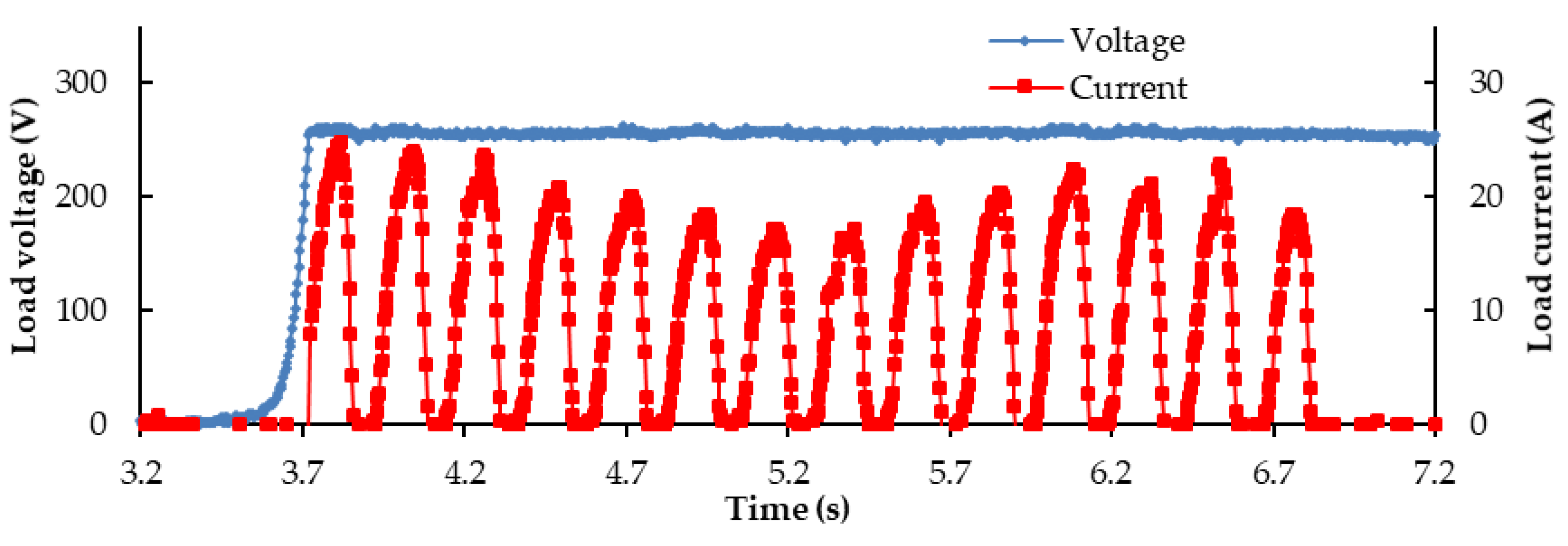
Figure 11 shows the output voltage and current characteristics over time for the running vehicle. The velocity of vehicle was 19 km/h. The peak current for each ground-side coil was not consistent. This resulted from the vehicle not being controlled to drive strictly straight, and the lines connecting each ground-side coil being longer than those used during the bench tests. Note that the applied voltage from the filter output point to the ground-side coils was dropped from 626 to 361 Vrms because of the length of the line was increased to 23.5 m between the filter and the coils. The total amount of energy received by the vehicle in this experiment was 2.14 Wh.
Figure 12 shows the output voltage and current characteristics over time for the running vehicle. The velocity of the vehicle was 52 km/h. The waveform of load current was the same as with the 19-km/h experiment except for the last 4 peaks and the time scale (i.e. division of
x-axis on
Figure 11 is 0.5 s and 0.2 s on
Figure 12). This was due to the control delay in the inverter. The total energy received in that experiment was 0.5 Wh.
4. Discussion
Based on our experiments, we have come to the conclusion that in order to improve the effectiveness of the dynamic WPT system analyzed in this paper, one needs to solve the following problems. (a) Compensate the line impedance from source to the ground-side coils. The applied voltage at the ground-side coil is almost half of the output voltage at the filter. To solve this, the inverter should be put near the coils or compensated across capacitors. (b) Reduce the road-side loss. If more ground-side coils were added to the system, the loss increased. To reduce this, a switching method might be developed. (c) Compare the PS system and series–series (SS) system. This paper focused on a parallel-series based dynamic WPT system. However, we also tested a series-series based dynamic WPT system in previous research [
15]. One should compare these two systems. (d) Increase receiving power between ground-side coils. The system examined in this paper had power drops between coils. A control method should be developed to increase the receiving power; i.e., an AC/DC converter with a feedback loop for power constant.
Table 6 shows a table that summarizes the experimental results contained in this paper. Total received energy and total energy conversion efficiency indexes are proposed to compare dynamic WPT systems. However, efficiency is not a time-independent variable and is not sufficient to demonstrate the performance of a dynamic WPT system. Total energy conversion efficiencies for real-car tests were difficult to establish, because of inconsistent start time when measuring passing’s of the vehicle over ground-side coils. We considered that the total received energy is a robust index, which depends on vehicle velocity and input power or energy.
5. Conclusions
This paper has examined a 25-kW, PS topology based dynamic WPT system, based on a stationary WPT system and proposed reference indexes for a dynamic WPT system. First of all, the theoretical analysis developed in this paper concluded that the considered system could use an equivalent circuit to the one used for stationary WPTs. After that, the WPT system was empirically tested to validate the theoretical analysis under several conditions. Finally, to compare the performance of dynamic WPT systems under various conditions, we have advanced two variables: The total energy conversion efficiency and total receiving energy.
Author Contributions
Conceptualization, T.F., H.K. and Y.K.; data curation, T.F. and H.K.; formal analysis, H.U.; funding acquisition, H.K. and Y.K.; investigation, T.F. and H.U.; project administration, H.K. and Y.K.; resources, H.K.; supervision, Y.K.; validation, T.F.; visualization, T.F. and H.U.; writing—original draft, T.F.; writing—review and editing, H.K., H.U. and Y.K.
Funding
This research was funded by New Energy and Industrial Technology Development Organization, grant number 1208007.
Conflicts of Interest
The authors declare no conflict of interest. The sponsors had no role in the design, execution, interpretation, or writing of the study. The co-authors T.F. and H.K. are employee of Technova Inc. The company had a role in the decision to publish the results. And the co-authors T.F. and H.K did all the work of this paper during working time of Technova.
References
- International Organization for Standardization. Electrically Propelled Road Vehicles-Magnetic Field Wireless Power Transfer-Safety and Interoperability Requirements; ISO/PAS 19363:2017; International Organization for Standardization: Geneva, Switzerland, 2017. [Google Scholar]
- International Electrotechnical Commission. Electric Vehicle Wireless Power Transfer (WPT) Systems—Part 1: General Requirements; IEC 61980-1:2015; International Electrotechnical Commission: Geneva, Switzerland, 2015. [Google Scholar]
- Society of Automotive Engineers recommended practice J2954. Wireless Power Transfer for Light-Duty Plug-In/Electric Vehicles and Alignment Methodology J2954_201904; Society of Automotive Engineers Recommended Practice: Warrendale, PA, USA, 2019. [Google Scholar]
- Low, Z.N.; Chinga, R.A.; Tseng, R.; Lin, J. Design and test of a high-power high-efficiency loosely coupled planar wireless power transfer system. IEEE Trans. Ind. Electron. 2008, 56, 1801–1812. [Google Scholar]
- Shimizu, R.; Kaneko, Y.; Abe, S. A new he core transmitter of a contactless power transfer system that is compatible with circular core receivers and H-shaped core receivers. In Proceedings of the 2013 3rd International Electric Drives Production Conference (EDPC), Nuremberg, Germany, 29–30 October 2013; pp. 369–375. [Google Scholar]
- Diekhans, T.; Doncker, R.W. A dual-side controlled inductive power transfer system optimized for large coupling factor variations and partial load. IEEE Trans. Power Electron. 2015, 30, 6320–6328. [Google Scholar] [CrossRef]
- Takanashi, H.; Sato, Y.; Kaneko, Y.; Abe, S.; Yasuda, T. A large air gap 3 kW wireless power transfer system for electric vehicles. In Proceedings of the 2012 IEEE Energy Conversion Congress and Exposition (ECCE), Raleigh, NC, USA, 15–20 September 2012; pp. 269–274. [Google Scholar]
- Imura, T.; Okabe, H.; Hori, Y. Basic experimental study on helical antennas of wireless power transfer for Electric Vehicles by using magnetic resonant couplings. In Proceedings of the 2009 IEEE Vehicle Power and Propulsion Conference, Dearborn, MI, USA, 7–11 September 2009; pp. 936–940. [Google Scholar]
- Nagatsuka, Y.; Ehara, N.; Kaneko, Y.; Abe, S.; Yasuda, T. Compact contactless power transfer system for electric vehicle. In Proceedings of the IEEE 2010 International Power Electronics Conference-ECCE, Sapporo, Japan, 21–24 June 2010; pp. 807–813. [Google Scholar]
- Ombach, G.; Kurschner, D.; Mathar, S.; Chlebosz, W. Optimum magnetic solution for interoperable system for stationary wireless EV charging. In Proceedings of the 2015 Tenth International Conference on Ecological Vehicles and Renewable Energies (EVER), Monte Carlo, Monaco, 31 March–2 April 2015; pp. 1–8. [Google Scholar]
- Hanazawa, M.; Ohira, T. Power transfer for a running automobile. In Proceedings of the 2011 IEEE MTT-S International Microwave Workshop Series on Innovative Wireless Power Transmission: Technologies, Systems, and Applicationsin, Kyoto, Japan, 12–13 May 2011; pp. 77–80. [Google Scholar]
- Covic, G.A.; Boys, J.T. Modern trends in inductive power transfer for transportation applications. IEEE J. Emerg. Sel. Top. Power Electron. 2013, 1, 28–41. [Google Scholar] [CrossRef]
- Kim, J.; Kim, J.; Kong, S.; Kim, H.; Suh, I.-S.; Suh, N.P.; Cho, D.-H.; Kim, J.; Ahn, S. Coil design and shielding methods for a magnetic resonant wireless power transfer system. Proc. IEEE 2013, 101, 1332–1342. [Google Scholar] [CrossRef]
- Lu, F.; Zhang, H.; Hofmann, H.; Mi, C.C. A dynamic charging system with reduced output power pulsation for electric vehicles. IEEE Trans. Ind. Electron. 2016, 63, 6580–6590. [Google Scholar] [CrossRef]
- Fujita, T.; Yasuda, T.; Akagi, H. A dynamic wireless power transfer system applicable to a stationary system. IEEE Trans. Ind. Appl. 2017, 53, 3748–3757. [Google Scholar] [CrossRef]
- Jeong, S.; Jang, Y.J.; Kum, D. Economic analysis of the dynamic charging electric vehicle. IEEE Trans. Power Electron. 2015, 30, 6368–6377. [Google Scholar] [CrossRef]
- Wang, C.S.; Covic, G.A.; Stielau, O.H. Power transfer capability and bifurcation phenomena of loosely coupled inductive power transfer systems. IEEE Trans. Ind. Electron. 2004, 51, 148–157. [Google Scholar] [CrossRef]
- Sato, F.; Murakami, J.; Suzuki, T.; Matsuki, H.; Kikuchi, S.; Harakawa, K.; Osada, H.; Seki, K. Contactless energy transmission to mobile loads by CLPS-test driving of an EV with starter batteries. IEEE Trans. Magn. 1997, 33, 4203–4205. [Google Scholar] [CrossRef]
- Showa Aircraft Industry Co. Ltd.; Tohoku University; Nissan Motor Co. Ltd. R&D Program for Innovative Energy Efficiency Technology, Exploratory Research Phase, a Development of Inductive Power Supply System for Moving Vehicles (FY2010–FY2012) FY2012 Final Report; Japan no. 20140000000045; NEDO: Kawasaki, Japan, 2014.
- Huh, J.; Lee, S.W.; Lee, W.Y.; Cho, G.H.; Rim, C.T. Narrow-width inductive power transfer system for online electrical vehicles. IEEE Trans. Power Electron. 2011, 26, 3666–3679. [Google Scholar] [CrossRef]
- Covic, G.A.; Boys, J.T.; Kissin, M.L.G.; Lu, H.G. A three-phase inductive power transfer system for roadway-powered vehicles. IEEE Trans. Ind. Electron. 2007, 54, 3370–3378. [Google Scholar] [CrossRef]
- Ean, K.K.; Imura, T.; Hori, Y. New Wireless Power Transfer via Magnetic Resonant Coupling for Charging Moving Electric Vehicle. In Proceedings of the EVTeC and APE Japan 2014, Yokohama, Japan, 22–24 May 2014; pp. 1–5. [Google Scholar]
- Kim, J.W.; Son, H.-C.; Kim, D.; Yang, J.; Kim, K.; Lee, K.; Park, Y. Wireless power transfer for free positioning using compact planar multiple self-resonators. In Proceedings of the 2012 IEEE MTT-S International Microwave Workshop Series on Innovative Wireless Power Transmission: Technologies, Systems, and Applications, Kyoto, Japan, 10–11 May 2012; pp. 127–130. [Google Scholar]
- Prasanth, V.; Bauer, P. Distributed IPT systems for dynamic powering: Misalignment analysis. IEEE Trans. Ind. Electron. 2014, 61, 6013–6021. [Google Scholar] [CrossRef]
- Fujita, T.; Kishi, H. A study of a dynamic wireless power transfer system based on parallel- series resonant topology-Bench test and real car test. In Proceedings of the EVS31 and EVTeC2018, Kobe, Japan, 30 September–3 October 2018. [Google Scholar]
- Fujita, T.; Yasuda, T.; Akagi, H. A wireless power transfer system with a double-current rectifier for EVs. In Proceedings of the 2016 IEEE Energy Conversion Congress and Exposition (ECCE), Milwaukee, WI, USA, 18–22 September 2016; pp. 1–7. [Google Scholar]
- Chigira, M.; Nagatsuka, Y.; Kaneko, Y.; Abe, S.; Yasuda, T.; Suzuki, A. Small-size light-weight transformer with new core structure for contactless electric vehicle power transfer system. In Proceedings of the 2011 IEEE Energy Conversion Congress and Exposition, Phoenix, AZ, USA, 17–22 September 2011; pp. 260–266. [Google Scholar]
Figure 1.
Construction of the experimental dynamic wireless power transfer (WPT) system.
Figure 1.
Construction of the experimental dynamic wireless power transfer (WPT) system.
Figure 2.
Photographs of the WPT coils tested in this paper. (a) Ground-side coil, (b) vehicle-side coil.
Figure 2.
Photographs of the WPT coils tested in this paper. (a) Ground-side coil, (b) vehicle-side coil.
Figure 3.
Experimental parameters of the WPT coils in case of the occurrence of misalignment. (a) Measured self and mutual inductances. (b) Measured equivalent resistances.
Figure 3.
Experimental parameters of the WPT coils in case of the occurrence of misalignment. (a) Measured self and mutual inductances. (b) Measured equivalent resistances.
Figure 4.
Equivalent circuit to the stationary WPT system.
Figure 4.
Equivalent circuit to the stationary WPT system.
Figure 5.
Equivalent circuit for the dynamic WPT system, with two ground-side coils.
Figure 5.
Equivalent circuit for the dynamic WPT system, with two ground-side coils.
Figure 6.
Experimental results of the stationary WPT system at the aligned condition as a function of input voltage VDC.
Figure 6.
Experimental results of the stationary WPT system at the aligned condition as a function of input voltage VDC.
Figure 7.
Photograph of the experimental dynamic WPT system in bench test.
Figure 7.
Photograph of the experimental dynamic WPT system in bench test.
Figure 8.
Experimental results of the dynamic WPT system in the bench test at RL = 7.6 Ω.
Figure 8.
Experimental results of the dynamic WPT system in the bench test at RL = 7.6 Ω.
Figure 9.
Experimental results of the dynamic WPT system in the bench test at VL = 265 V.
Figure 9.
Experimental results of the dynamic WPT system in the bench test at VL = 265 V.
Figure 10.
Photograph of the dynamic WPT system in the real-car test.
Figure 10.
Photograph of the dynamic WPT system in the real-car test.
Figure 11.
Experimental results of the load voltages and currents in the real-car test at vehicle velocity vx = 19 km/h.
Figure 11.
Experimental results of the load voltages and currents in the real-car test at vehicle velocity vx = 19 km/h.
Figure 12.
Experimental results of the load voltages and currents in the real-car test at vehicle velocity vx = 52 km/h.
Figure 12.
Experimental results of the load voltages and currents in the real-car test at vehicle velocity vx = 52 km/h.
Table 1.
Component specifications of the dynamic WPT system.
Table 1.
Component specifications of the dynamic WPT system.
| System Components | Specifications |
|---|
| Output power | Max 25 kW |
| Air gap | 170 mm |
| Frequency | 85 kHz |
| AC/DC converter | Variable output voltage 1 |
| Inverter | Full SiC FETs 2 |
| Rectifier | Double current rectifier |
| Vehicle-side coil cooling | Water cooling |
Table 2.
Specifications of the WPT coils.
Table 2.
Specifications of the WPT coils.
| Side of Coil | Size (mm) | Winding |
|---|
| Ground-side | 620 × 600 × 40 | 6 T × 10 p 1 |
| Vehicle-side | 430 × 374 × 38.5 | 45 T × 1 p |
Table 3.
Experimental parameters of 25-kW WPT system at aligned condition.
Table 3.
Experimental parameters of 25-kW WPT system at aligned condition.
| LN | LS | rN | rS | k |
|---|
| 22.4 μH | 658 μH | 51.6 mΩ | 1360 mΩ | 0.235 |
Table 4.
Experimental parameters of 25-kW PWT system.
Table 4.
Experimental parameters of 25-kW PWT system.
| CN | CS | LL1 | LL2 | RL |
|---|
| 17.3 nF | 13.7 nF | 300 μH | 300 μH | 7.6 Ω |
Table 5.
Experimental circuit parameters of real-car test.
Table 5.
Experimental circuit parameters of real-car test.
| CN | CS | L1 | L2 | VL |
|---|
| 17.3 nF | 13.7 nF | 300 H | 300 H | 260 V |
Table 6.
Summary of experimental results.
Table 6.
Summary of experimental results.
| Test Result in this Paper | Receiving Power (kW) | Efficiency | Total Energy Conversion Efficiency | Total Received Energy (Wh) |
|---|
| Stationary WPT system | 25 | 85.5% | -- | -- |
| Bench test for Resistance | 10.6 | 79.1% | 72.45% | 301 |
| Bench test for Battery | 10.1 | 79.2% | 56.92% | 149 |
| Real-car test (vx = 19 km/h) | 6.5 | NA | NA | 2.14 |
| Real-car test (vx = 52 km/h) | 5.9 | NA | NA | 0.5 |
© 2019 by the authors. Licensee MDPI, Basel, Switzerland. This article is an open access article distributed under the terms and conditions of the Creative Commons Attribution (CC BY) license (http://creativecommons.org/licenses/by/4.0/).


