1. Introduction
Improvement of motor efficiency is an important issue for increasing the electric power efficiency of electric vehicles (EV). Generally, motor loss, which consists mainly of iron loss and copper loss is strongly influenced by the magnetic properties of the electrical steels [
1,
2] used in motor cores. In the case of EV, since traction motors are driven under a wide range of conditions [
3], high efficiency or high torque is required in each driving condition. Under these circumstances, low iron loss and high flux density (high permeability) are demanded in electrical steels. Reduction of iron loss can contribute to downsizing of motors, which is effective for reducing motor weight through high revolution speed. It is known that improvement in the property of magnetization (flux density) in electrical steels can improve motor torque properties. (Hereinafter, the value of the flux density when a magnetic field of a given strength is applied is called “material flux density.” A notation such as
B50 for the material flux density means the flux density at the magnetic field strength of 5000 A/m.) This means core materials having high flux density can realize motor size reduction under given torques. Equally, reduction of the motor current is achievable if the size of the motor and the torque are kept the same value, and this leads to a reduction of copper loss.
As for the magnetic properties of electrical steels, since a trade-off relationship sometimes exists between iron loss and material flux density, it is difficult to realize both properties simultaneously. Therefore, choosing suitable core materials by considering the motor driving condition is important. At the same time, proper indicators and analysis methods are needed for appropriate selection of core materials. Previously, several researches have been carried out to investigate the influence of core materials on motors [
4,
5]. However, few research can be found on core materials focusing on basic magnetic properties systematically.
Currently, synchronous motors with permanent magnets are commonly used as traction motors of EV and HEV because of their high efficiency. Hence, in this study, influences of core material’s magnetic properties on the motor performance were studied in order to establish proper indicators of material and to contribute to new material development, using the SPM type brushless DC motor (BLDC motor). In this study, the effects of the magnetic properties of electrical steels on motor loss and torque are discussed based on the measured results obtained with BLDC motors. Additionally, to understand the origin of the higher harmonic iron loss component in inverter-driven motors, which are commonly used in EVs, inverter-fed magnetic measurements were carried out, and the influence of the material thickness on core loss under PWM excitation conditions was evaluated.
Finally, electrical steels suitable for EV motors are described based on the evaluation considering motor operation conditions.
2. Evaluation of Motor Properties
2.1. Experimental Procedure
The influence of the magnetic properties of non-oriented electrical steels was evaluated by using a SPM brushless DC motor (8 poles, 12 slots, concentrated windings) [
6]. The specifications of the motor are shown in
Table 1. In the evaluation, the tested motor was connected to a load motor through a torque sensor and tachometer, and the maximum efficiency when the applied torque was increased gradually from the no-load state at a revolution speed of 2100 rpm was taken as a candidate motor property. The maximum efficiencies were obtained around the revolution speed of 1500 rpm. The torque constants at 1500 rpm were calculated from the measured torques and currents.
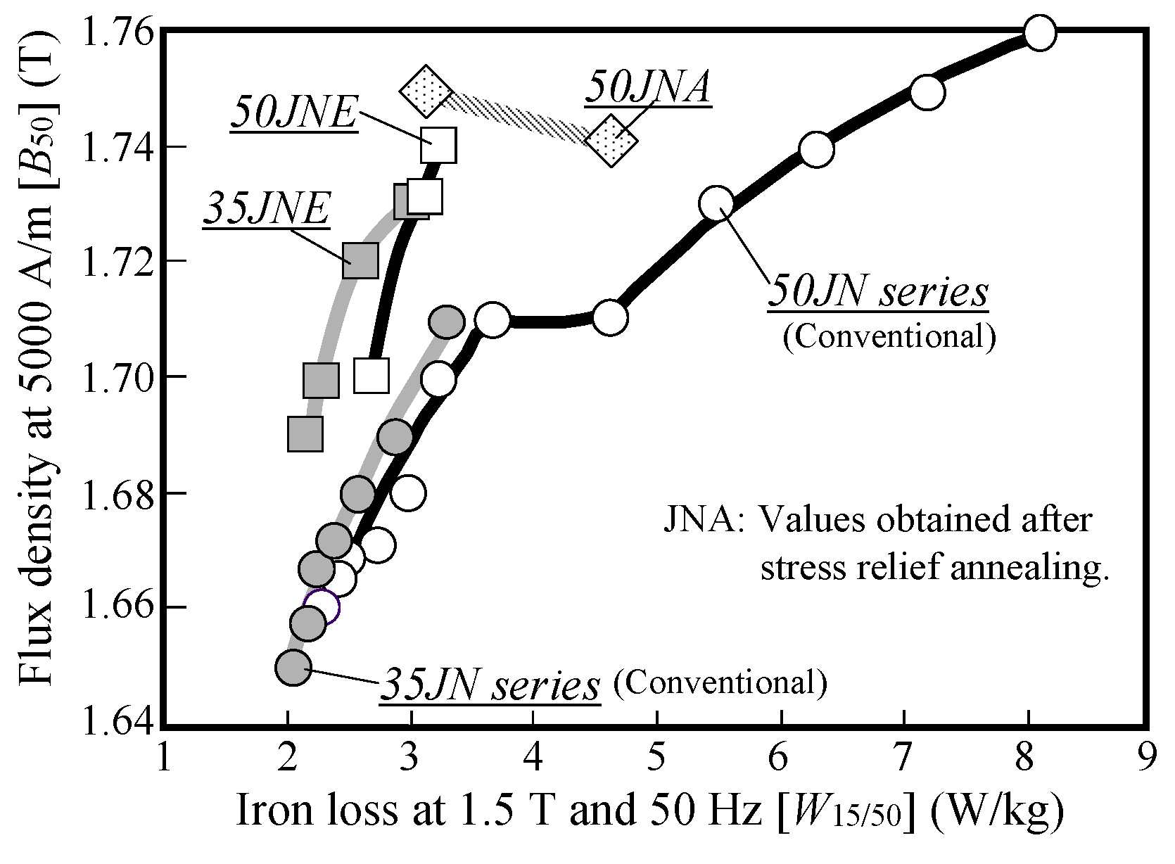
For the stator materials, several kinds of electrical steels were chosen from the commercial electrical steel products shown in
Figure 1 to evaluate the influence of magnetic properties on motor efficiency, iron loss, and copper loss. In
Figure 1, the 35JN series and 50JN series are conventional non-oriented electrical steels with thicknesses of 0.35 mm and 0.50 mm, respectively. Here, the head figures of each series indicate the sheet thickness (e.g., 35JN indicates a thickness of 0.35 mm). JNA
® series is a material which show good magnetic properties after stress relief annealing. The values of JNA in
Figure 1 are the magnetic properties measured after stress relief annealing in 750 °C for 2 h. The JNE
® series (35JNE and 50JNE) shows high material flux density
B50 and low iron loss
W15/50. Here, a notation such as
W15/50 means iron loss at a flux density of 1.5 T and frequency of 50 Hz. Magnetic properties were measured by the Epstein method using the sample cut along rolling direction and the sample cut along the transverse direction toward rolling direction.
2.2. Result of Motor Evaluation
The relationships between the maximum motor efficiency and magnetic properties of the stator materials are shown in
Figure 2. In
Figure 2, the horizontal axes in (a), (b), and (c) are
W15/50,
W15/100,
W10/400, and the correlation coefficients for the relationship in (a), (b), and (c) were 0.65, 0.80, and 0.94, respectively. The highest correlation was obtained when
W10/400 was chosen as the material iron loss. Material iron loss
W15/50, which has been used conventionally as an indicator for electrical steel, did not show a good correlation with motor efficiency. This means that iron loss at low frequencies is not suitable for prediction of the performance of BLDC motors.
In the BLDC motor used in this study, the peak flux density in the teeth of the stator core was about 1.6 T, and the fundamental frequency at maximum efficiency was about 100 Hz. Therefore, the correlation with W15/100 should be the highest if the loss at the fundamental frequency was the largest part of motor loss. However, the highest correlation was obtained when 400 Hz was chosen as the material iron loss. This fact indicates that the influence of higher harmonics in the flux waveforms is significant in BLDC motors, and the iron loss measured under high frequency conditions is important for core material evaluation. Here, the peak flux density at W10/400 differs from the peak flux density in the stator core. The reason why W10/400 showed a good correlation with the motor efficiency is that the material iron loss at 1.0 T has a linear relationship with the material iron losses at higher flux densities such as 1.6 T. Moreover, measurement of material iron loss at high flux density such as 1.6 T and a frequency of 400 Hz is sometimes difficult because of the performance limitations of measuring apparatuses. Therefore, W10/400 is a useful indicator for the evaluation of materials used in BLDC motor cores.
Frequency components higher than the fundamental frequency are contained in the flux density waveforms of the stator core due to armature mmf [
7] and the carrier frequency of the inverter. Although the frequencies of these higher harmonics are higher than 400 Hz, the material iron loss at 400 Hz has a roughly linear relationship with the losses at higher frequencies over 400 Hz. From this viewpoint as well,
W10/400 is a good indicator for evaluation of core materials for BLDC motors.
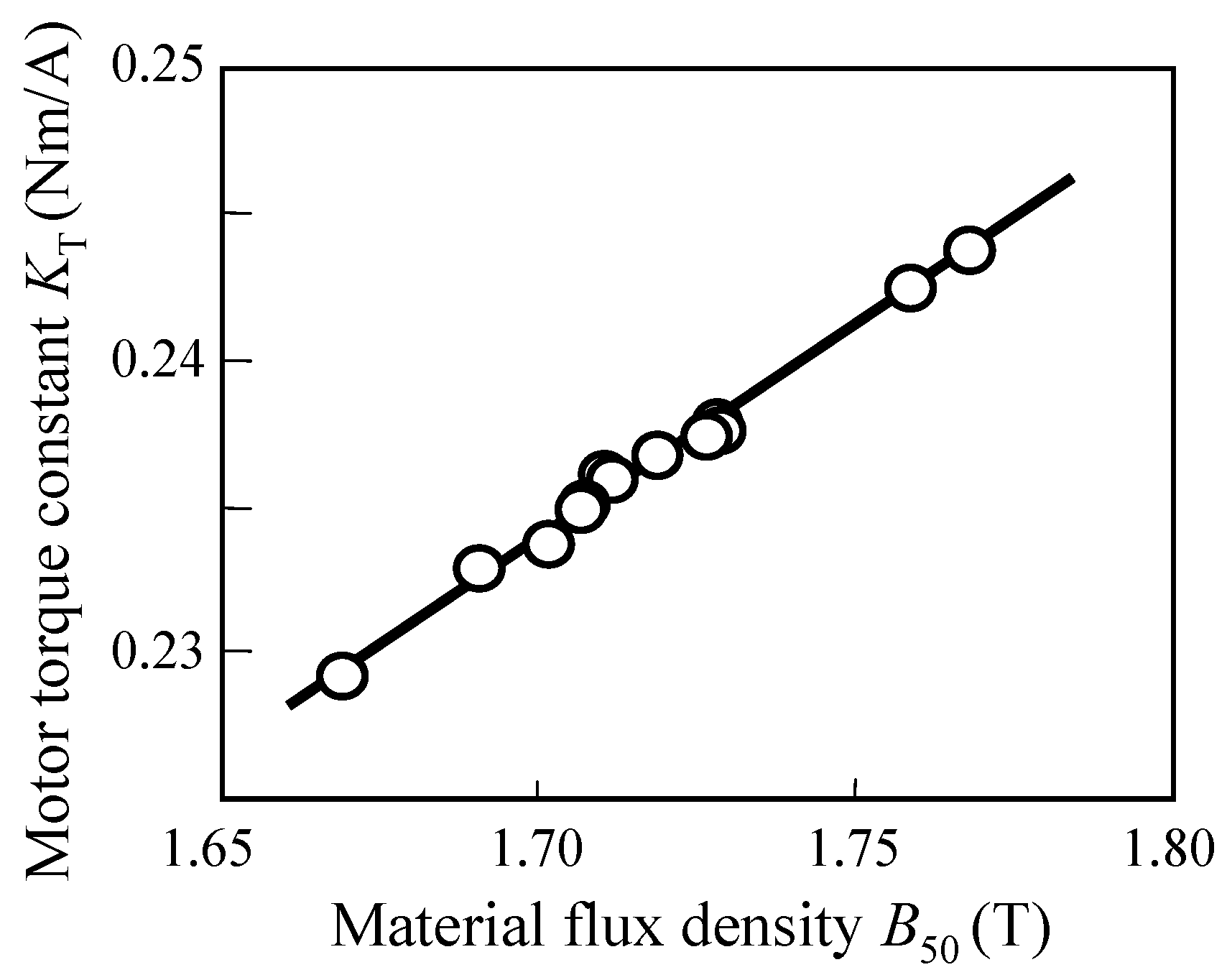
Figure 3 shows the relationship between the material flux density
B50 and the motor torque constant. As can be seen in the graph, the torque constants increased linearly with increasing material flux density
B50. This result shows that electrical steels having high
B50 are effective for obtaining high torque. In the motor used in this study, the flux density in the stator yoke was almost 1.6 T, and this value was roughly close to the material flux density
B50. This means
B50 is a good indicator for predicting the motor torque. However, if the peak flux density in a motor core is much lower,
B50 is not a good indicator because the flux density level is different from the excitation condition of the motor core.
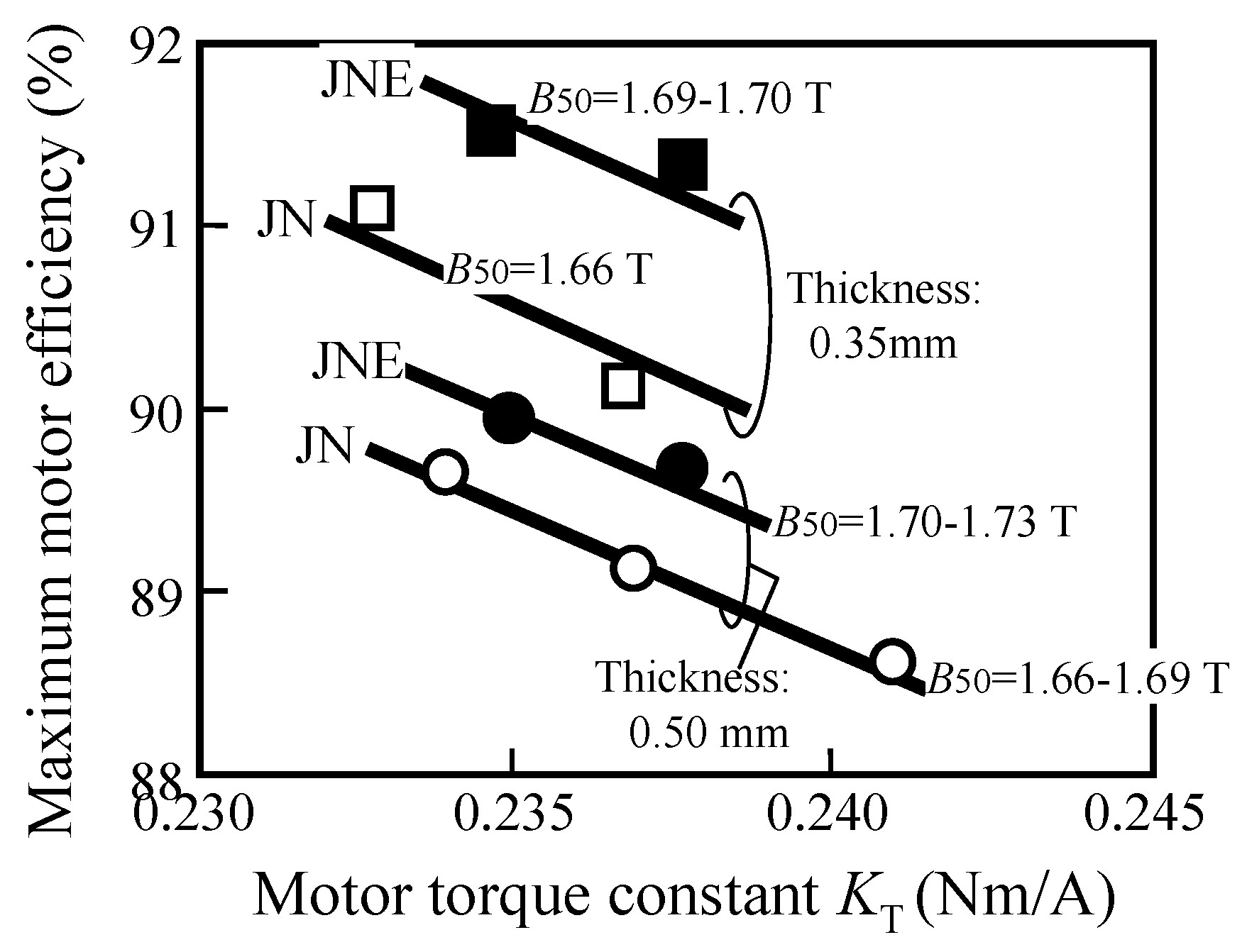
Figure 4 shows the relationship between the torque constant and maximum efficiency. As can be seen in this graph, higher efficiencies are achieved in the JNE
® series which has higher flux densities
B50 while keeping low iron loss. In a comparison of products having the same sheet thickness, higher efficiencies are achieved in JNE than in conventional material JN for the same levels of the torque constant. The advantage of the JNE series in the torque property shown in
Figure 4 is based on its high
B50 without deterioration of iron loss. For EV traction motors, high torque and low loss must be achieved at the same time. Therefore, improvement of material flux density as it achieved in JNE is effective for improving the total performance of EV motors.
3. Material Evaluation under Inverter Excitation Condition
3.1. Experimental Procedure
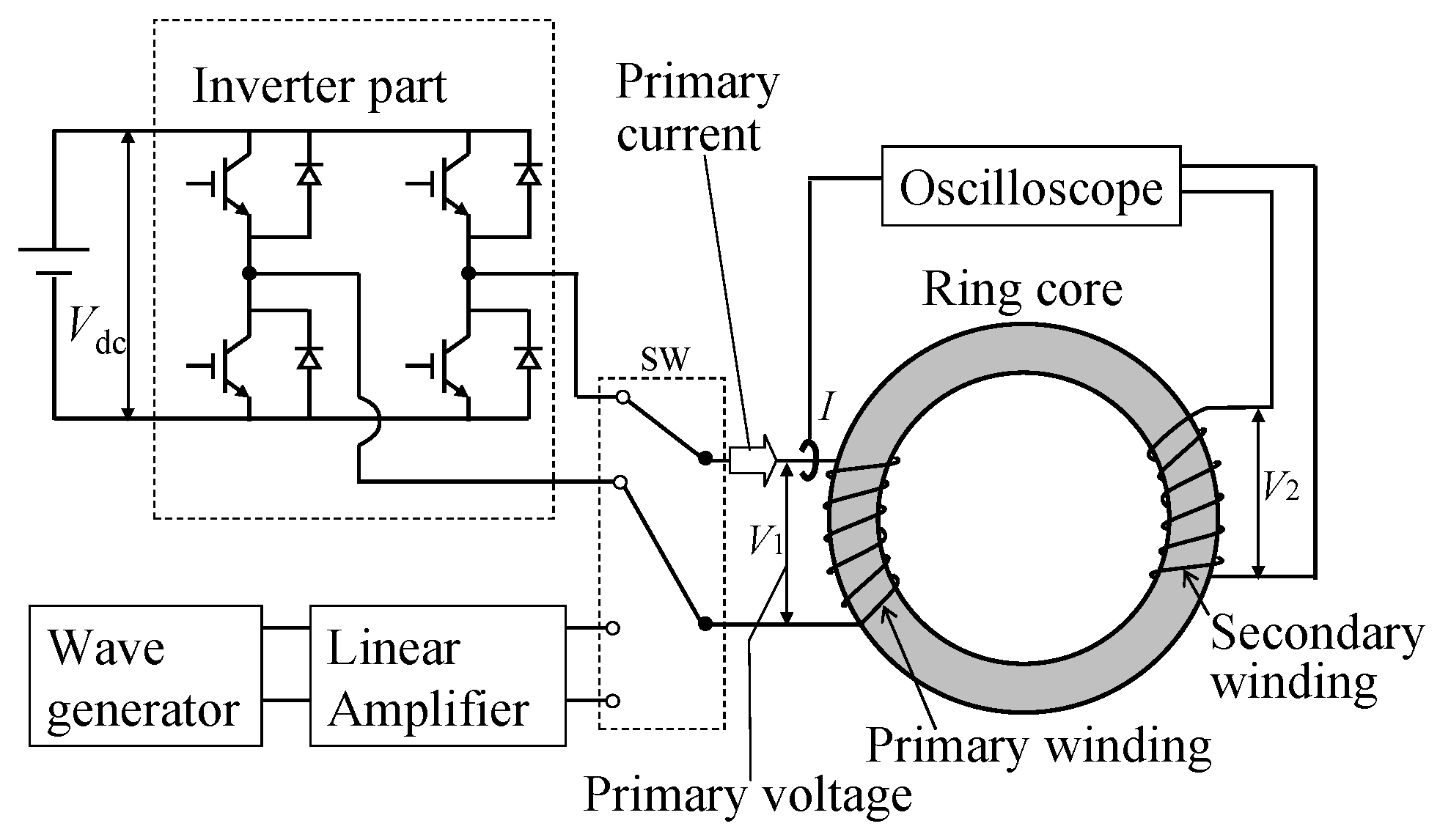
Figure 5 shows the experimental system for PWM excitation using an inverter. In the inverter part, a single phase Si-N channel IGBT was used. This system also has a linear amplifier excitation system for comparison with the usual iron loss in the sinusoidal condition.
In both the measurements with PWM excitation of inverter and with sinusoidal excitation, the fundamental frequency was 50 Hz and the maximum flux density was 1.5 T. In the inverter excitation measurement, the carrier frequency was changed between 500 Hz and 20 kHz, and the modulation index was changed between 0.1 and 1.0.
As samples for magnetic measurement, ring core samples having an outer diameter of 80 mm and inner diameter of 60 mm were prepared. The turn numbers of the primary and secondary windings were 150 and 100, respectively. The flux density (B) of the core was measured by the output voltage of the secondary coil, and the strength of the magnetic field (H) was obtained by the current measured by the current sensor. Iron losses were derived by calculating the inner area of the B-H loops.
Electrical steels containing 3% silicon having sheet thicknesses of 0.50 mm, 0.35 mm, and 0.25 mm were prepared in the laboratory. Ring cores were prepared using these electrical steels by wire cutting followed by stacking so that the thickness of the core was 7 mm.
3.2. Results of Measurement under Inverter Excitation Condition
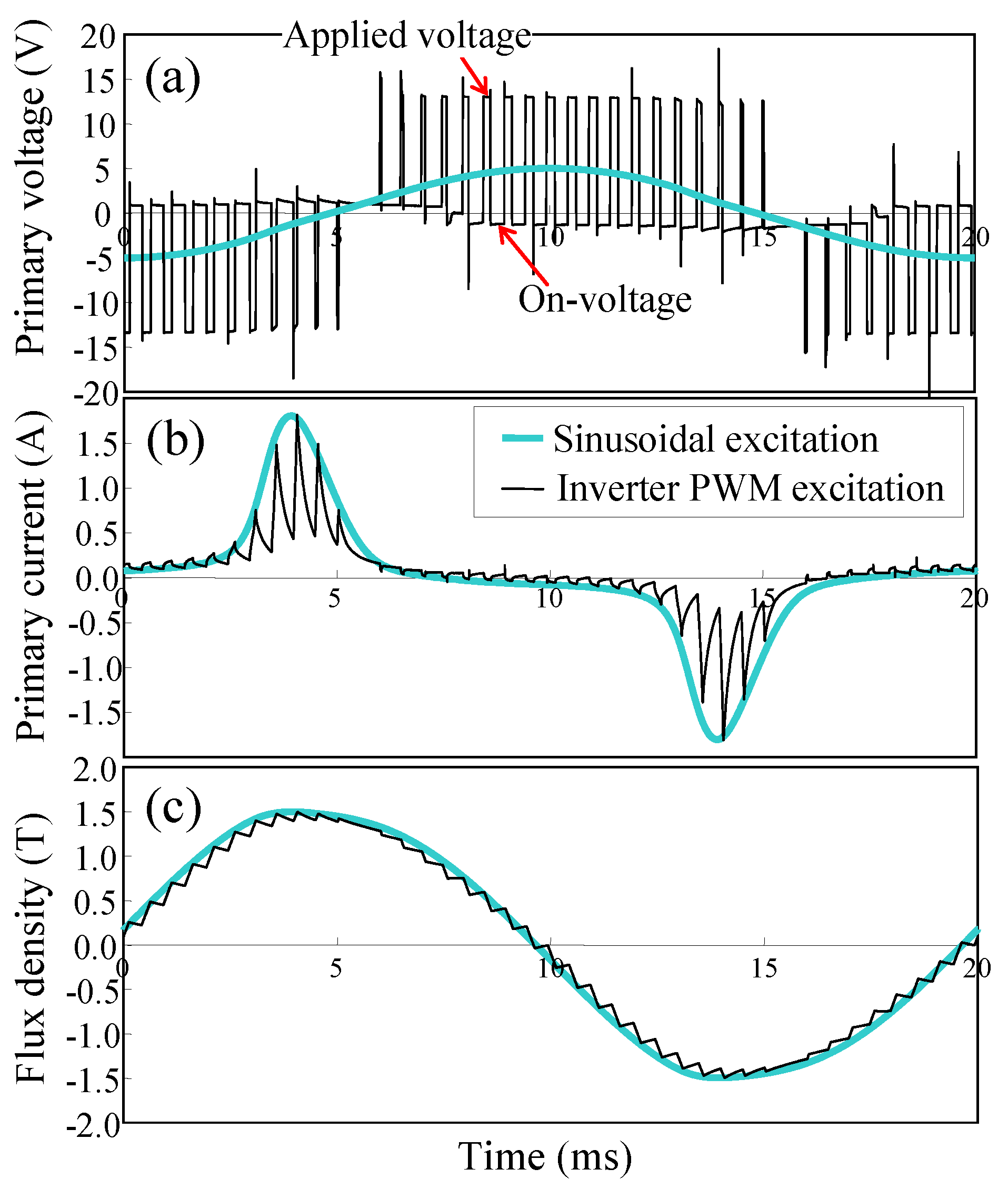
Figure 6 shows the waveforms of the applied voltage, excitation current, and flux density. Under the inverter excitation condition, the rectangular voltage waveform generated by the inverter caused sharp changes in current, resulting in high frequency components in the flux density waveform. Here, the high frequency components were twice the carrier frequency.
In the voltage waveform (a), ON-voltage [
8,
9], which is the opposite voltage component to the applied voltage can be recognized. As the ON-voltage keeps constant values at different applied voltages, the ratio of the ON-voltage with respect to the applied voltage is larger in cores with smaller cross-sectional areas [
10]. For this reason, the heights of the tested ring cores were controlled to be the same in this study.
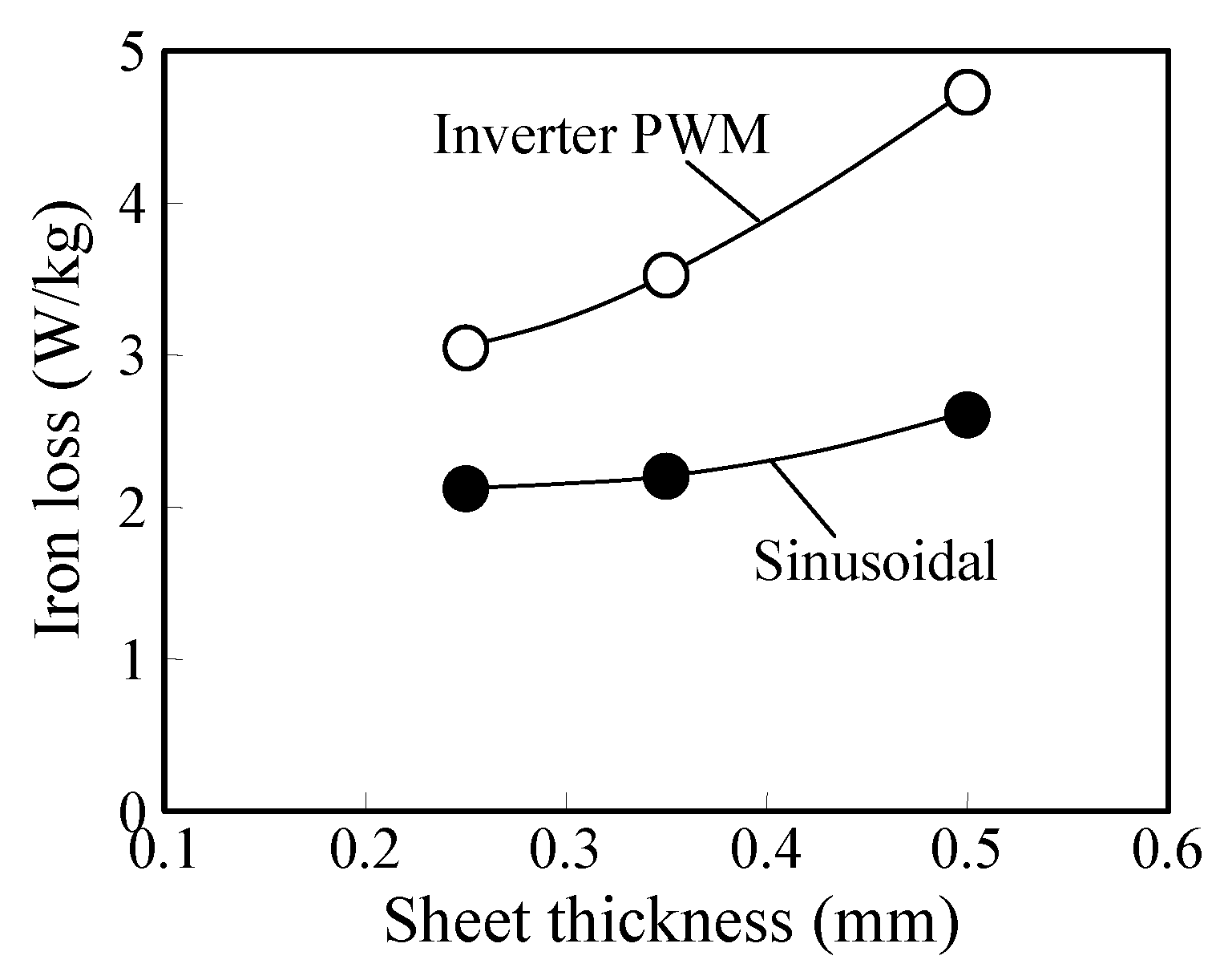
Figure 7 shows the dependence of iron loss on the sheet thickness under the usual sinusoidal excitation and inverter PWM excitation. As it is well known, iron loss increases with sheet thickness under sinusoidal excitation. In the inverter PWM excitation, the iron losses were larger than the losses in the sinusoidal condition, and the increasing tendency of iron loss with respect to the sheet thickness was prominent compared to that under sinusoidal excitation. From this result, under actual inverter-fed conditions, thinner gauge materials are more advantageous than thicker materials to suppress motor loss increase.
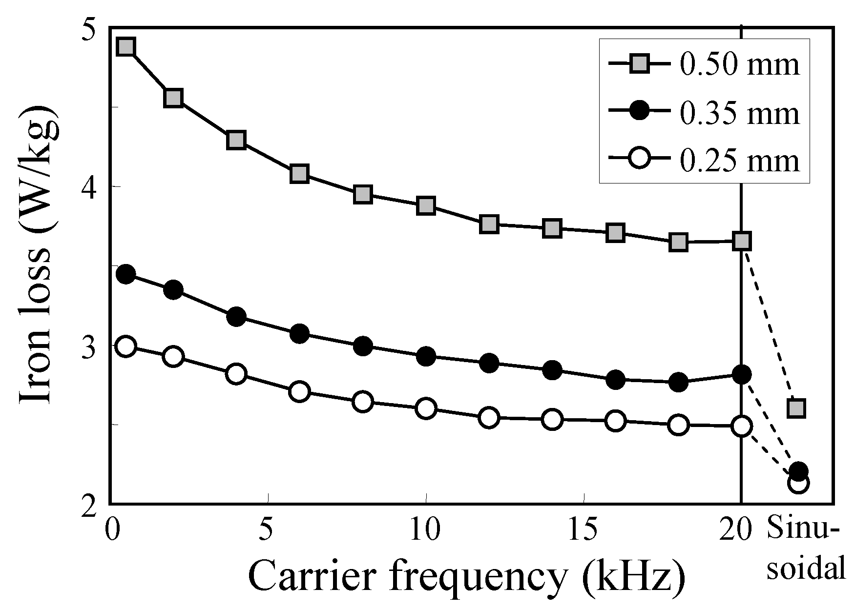
Figure 8 shows the dependences of iron loss on the carrier frequency under the inverter PWM excitation (modulation index: 0.4) for the materials with different thicknesses.
It is noted that an increase in iron loss occurs at low carrier frequencies, and this tendency is obvious in thicker materials. The differences between materials having different thicknesses are significant at lower carrier frequencies.
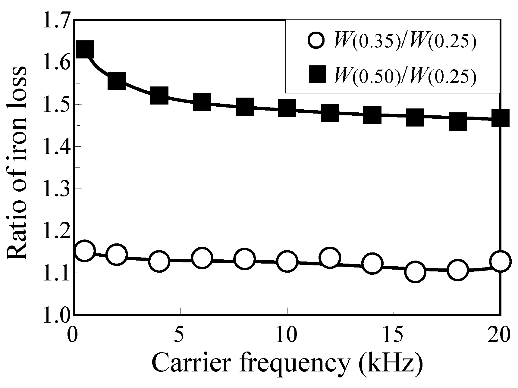
Figure 9 shows the ratios of the losses between the materials with different sheet thicknesses. Here,
W(0.25),
W(0.35), and
W(0.50) mean the losses measured with materials having thicknesses of 0.25 mm, 0.35 mm, and 0.50 mm, respectively. As can be seen in
Figure 9, the advantage of the 0.25 mm thick material in comparison with the 0.50 mm material was large, especially at low carrier frequencies. However, this tendency is not so apparent in the comparison between the 0.35 mm thick material and the 0.25 mm thick material.
Figure 8 also shows the iron losses under sinusoidal condition. The carrier frequency in the inverter-driven condition at 20 kHz is so high that the appearance of the waveform looks close to the waveform in the sinusoidal condition. However, the iron losses at the carrier frequency of 20 kHz are considerably higher than the losses under the sinusoidal condition. This means the increment of iron loss due to inverter excitation should be considered in loss evaluations of EV motors.
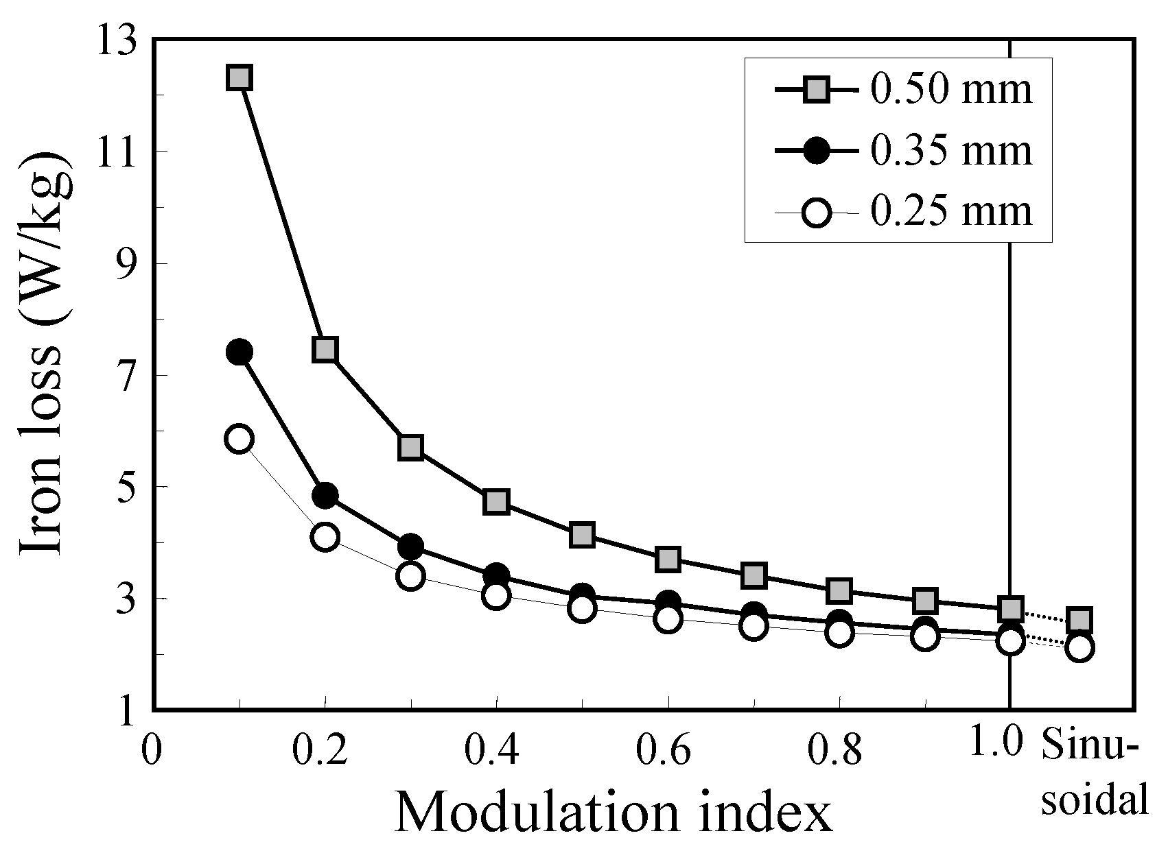
The dependence of iron loss on the modulation index is shown in
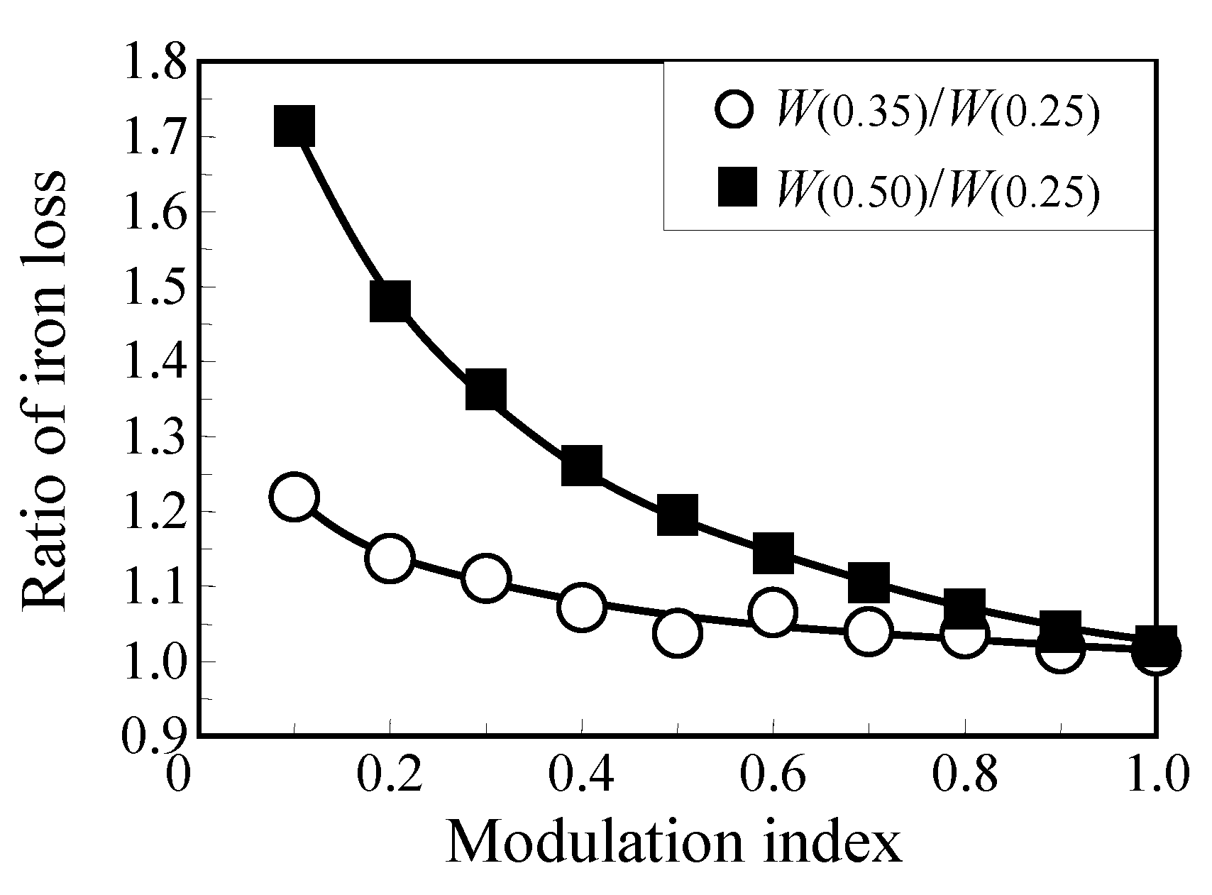
Figure 10 for the carrier frequency of 1.0 kHz. The ratios of the iron losses of materials with different thicknesses are shown in
Figure 11 as a function of the modulation index. In the measurements to obtain the data for
Figure 10, the peak flux density was controlled to be 1.5 T by changing the DC voltage of the inverter.
As can been in
Figure 10, iron loss under PWM excitation increased markedly with the decrease in the modulation index. From
Figure 11, it is obvious that thinner materials are more advantageous at lower modulation indexes.
Under actual EV driving conditions, the output voltage (effective value) of the inverter is controlled by changing the modulation index. On the other hand, in the measurements of this study, the DC voltage was changed to achieve the targeted maximum flux density. Therefore, the data in
Figure 11 do not show individual influence of the modulation index, but indicate the contribution of the modulation index when the DC voltage is adjusted cooperatively to obtain certain torque values.
The increase in iron loss under inverter excitation is attributed to the fact that the flux density waveforms in the core contain higher frequency components. Therefore, the increment of loss due to inverter excitation mainly originates from eddy current loss, resulting in the improvement of loss by thinner materials. Although the frequencies of the harmonic components are low under low carrier frequencies, the loss increases are significant because the amplitude of the harmonics is high. Under low modulation index conditions, higher voltages are output in a short time, resulting in a larger amplitude of higher harmonics.
This section has described the results of an analysis of iron loss under inverter excitation. It was found that iron loss increased more significantly in thicker materials under inverter excitation than under conventional sinusoidal waveform conditions. The increase of iron loss becomes larger at lower carrier frequencies and lower modulation indexes. Considering these results, thinner materials are advantageous for improving motor efficiency in EV motors driven by inverters.
4. Electrical Steels for EV Traction Motors
As described above, high material flux density while keeping low iron loss is needed to achieve high torque and high efficiency in EV traction motors. Furthermore, for lower iron losses in high frequency excitation conditions, especially when an inverter driven system is used, thinner gauge materials are advantageous because the eddy current loss can be suppressed effectively.
As mentioned earlier, the advantage of the high flux density material was confirmed in the motor evaluation using the JNE®, which has higher material flux density than conventional materials for the stator core of BLDC. Based on these results, a new material having higher flux density than the JNE series, which was named JNP®, were developed by using a texture (grain orientation distribution) control technique.
As thinner gauge materials which are advantageous under inverter driven conditions, 30JNE, 25JNE, and 20JNEH, whose thicknesses are 0.30 mm, 0.25 mm, and 0.20 mm, respectively, have been developed by applying the texture control techniques developed in JNE.
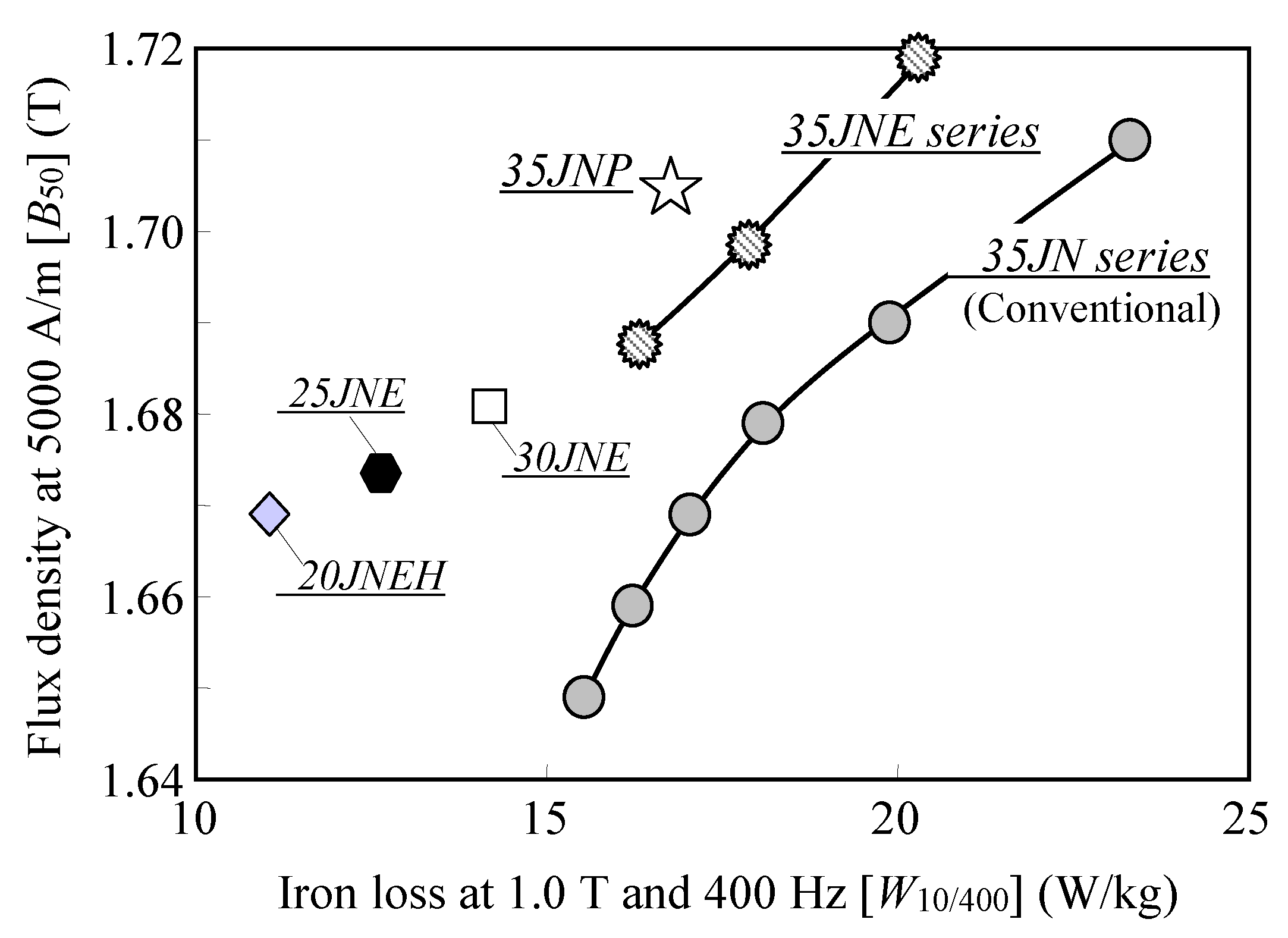
Figure 12 shows a map of the magnetic properties by iron loss W
10/400 and material flux density B
50. Here, the loss at 400 Hz, which was confirmed to be a suitable indicator for material evaluation for EV motors, was chosen for the horizontal axis. As can be seen in
Figure 12, the newly developed JNP [
2,
11] and thinner gauge materials (30JNE, 25JNE, 20JNEH [
2]) have expanded the variety of possible choice of core materials. Traction motors are designed so that the motor attains the traveling performance demanded in EV. These newly developed electrical steels, which cover a wide range of improved properties can contribute to improvement of EV performance through appropriate material selection for each motor design.
5. Conclusions
The influence of the magnetic properties of electrical steels on the motor performance was investigated by using laboratory BLDC motor and the material evaluation under PWM excitation. The following conclusions were obtained.
(1) Higher frequency iron loss than fundamental frequency of motors, such as 400 Hz in this study, is a dominant iron loss which decides efficiencies of BLDC motors.
(2) Core materials having higher flux densities are advantageous for achieving higher torque constants. Electrical steels that show high flux density and low iron loss, such as JNE®, realizes higher efficiencies while keeping higher toques.
(3) Iron losses are significantly high in thicker materials under the PWM excitation with inverter. Iron losses increase with the decrease in carrier frequencies under a constant DC voltage, and this tendency is significant in thicker materials.
(4) A remarkable increase of iron loss appears in lower modulation under a variable DC voltage condition, and this tendency is marked in thicker materials.
The results mentioned above shows that the materials having higher flux density and thinner gauge are advantageous to achieving high performances in motors. Based on this fact, high flux density electrical steels named JNP®, and thinner gauge electrical steels such as 30JNE, 25JNE, and 20JNEH, in which texture control techniques were applied, were developed. These materials can contribute to improved performances of EV traction motors through appropriate core material selection.
