Article

Electric Safety Challenges with a Conductive Electric Road System—Chassis Potential Modeling and Measurement

by
Francisco J. Márquez-Fernández
1,2,*,
Sönke Schuch
3,
Lars Lindgren
1 and
Mats Alaküla
1,2
1
Div. Industrial Electrical Engineering and Automation, Faculty of Engineering, Lund University, SE-223 63 Lund, Sweden
2
Swedish Electromobility Centre, SE-412 58 Gothenburg, Sweden
3
Institute for Power Electronics and Electrical Drives (ISEA), RWTH Aachen University, DE-520 66 Aachen, Germany
*
Author to whom correspondence should be addressed.
World Electr. Veh. J. 2019, 10(2), 30; https://doi.org/10.3390/wevj10020030
Submission received: 19 April 2019 / Revised: 10 May 2019 / Accepted: 20 May 2019 / Published: 24 May 2019

Abstract

:
Conductive Electric Road Systems (ERS) appear as a promising solution for the electrification of transportation, particularly for heavy vehicles and long-distance trips but also for light vehicles. Significant research efforts are currently devoted to the development of conductive ERS systems, with up to four pilot test sites with different technologies in operation only in Sweden. With the help of electric models and experimental measurements on a pilot test track, this article assesses the potential safety challenges associated with one aspect of this technology: the absence of a reliable protective earth connection while the vehicle is connected to the ERS power supply. The results highlight the importance of monitoring the chassis potential at all times and the need of an active safety mechanism to disconnect the vehicle from the ERS supply if a severe fault occurs.

1. Introduction

Electrification is nowadays one of the most widely spread strategies to reduce transport sector emissions [1]. The automotive market is experiencing a remarkable development towards electrification, and for the passenger car segment, there is a wide offer of models with a full electric or a plug-in hybrid electric drivetrain, allowing for pure electric driving over most of the driven distances. However, electrifying heavy-duty vehicles such as long-haul trucks and coaches is significantly more challenging, since these types of vehicle require large and heavy batteries to reach a useful driving distance, thus reducing the payload and making the whole case less feasible from an economic perspective.
In order to reduce the size of the battery while keeping the usability of the vehicle unchanged, dynamic charging could be used. With dynamic charging, energy is transferred to the vehicle while in motion. This energy may be used not only to propel the vehicle but also to charge the battery so that it can be used at a later stage. Electric Road Systems (ERS) represent the physical implementation of different dynamic charging principles: inductive, in which the power is transferred via coupled magnetic field, capacitive, using coupled electric field, and conductive, in which there is a physical connection, and the electric current flows directly between the electric road and the vehicle.
Previous work on the cost of different ERS concluded that, on the basis of data from today’s existing pilot test sites, conductive ERS can be built at a significant lower cost than the competing alternatives [2,3]. Moreover, conductive ERS placed at ground level (either under the vehicle or on the side) can be used by both heavy and light vehicles, resulting in a much lower total system cost from a societal perspective. Up to four pilot test sites for different conductive ERS are currently operating in Sweden, and the Swedish government has recently signed agreements with Germany [4] and France [5] to collaborate on the development of ERS technology. Therefore, an assessment of the safety challenges associated with this technology is necessary.
This article analyses one of the main safety hazards with all the conductive ERS proposed so far: the absence of a reliable protective earth connection. Since the vehicle is supplied with electricity using some kind of sliding contacts (“pick-ups”) that move relative to the power supply lines allowing the vehicle to connect/disconnect at any time, none of the proposed solutions can guarantee that a solid protective earth connection exists at all times while the vehicle is connected to the power supply. This in turn implies that, unlike what happens in trams and railways, the body of the vehicle cannot be connected to earth at all times, so potentially dangerous situations in which an insulation fault results in an energized vehicle body cannot be avoided completely.
Compared to Battery Electric Vehicles (BEVs), the electric power system of a vehicle running on a conductive ERS may not be completely isolated from earth potential, and as shown in the next section, at least part of the electric system on-board could be energized with respect to earth. Therefore, understanding the evolution of the chassis’ and vehicle body’s electrical potential during both normal and fault situations becomes safety-critical.

2. Materials and Methods

In order to assess the safety conditions of an electric vehicle (EV) supplied by a conductive ERS, an electrical model of the whole system (vehicle and infrastructure) implemented in LTSpice is proposed in this article. The model was used to estimate the chassis potential and the touch current under different operation conditions. Since the model relies on a number of input parameters such as insulation and parasitic impedances, which in turn depend on the physical implementation of both the ERS infrastructure and the vehicle itself, experimental tests were conducted in order to validate the simulation results.
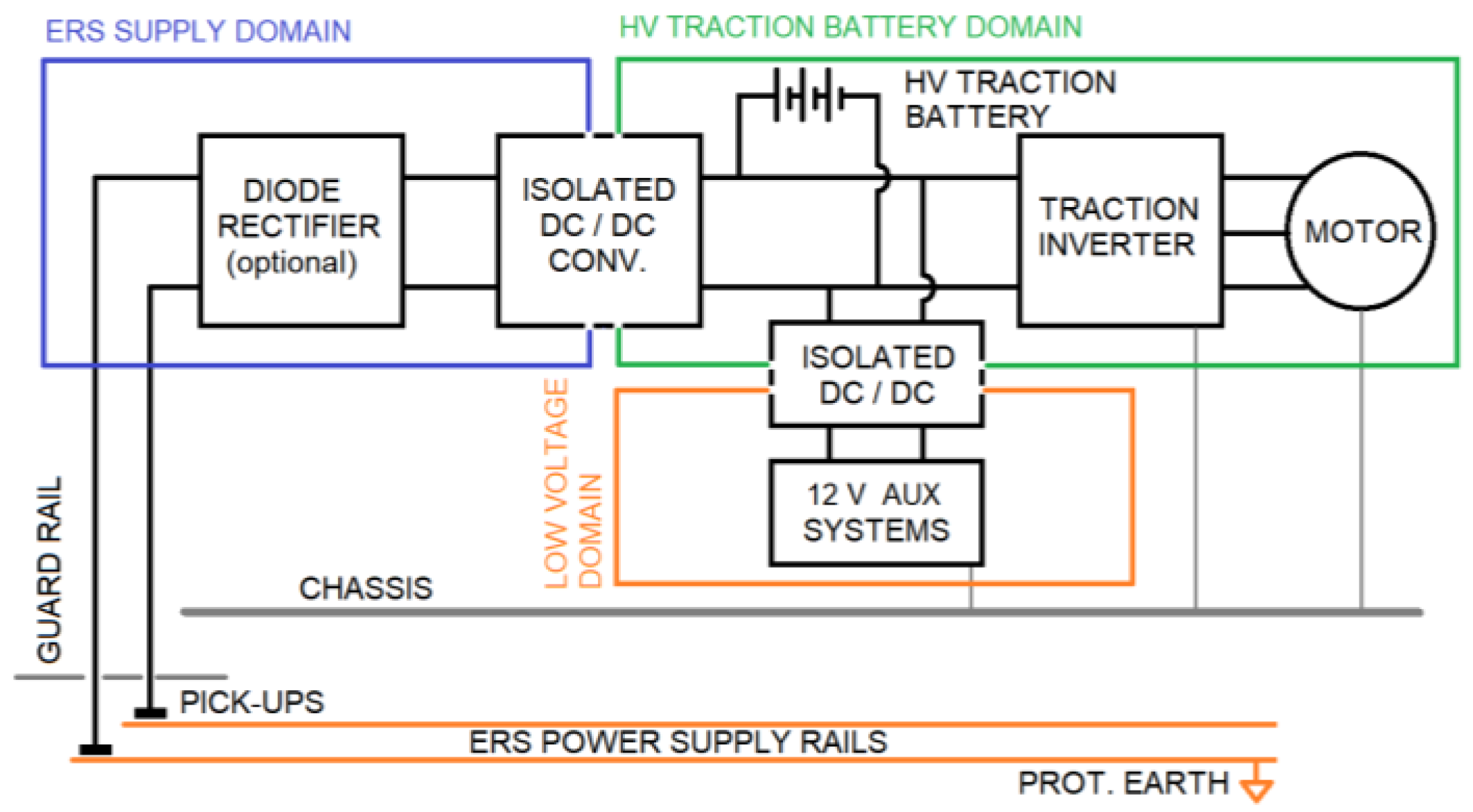
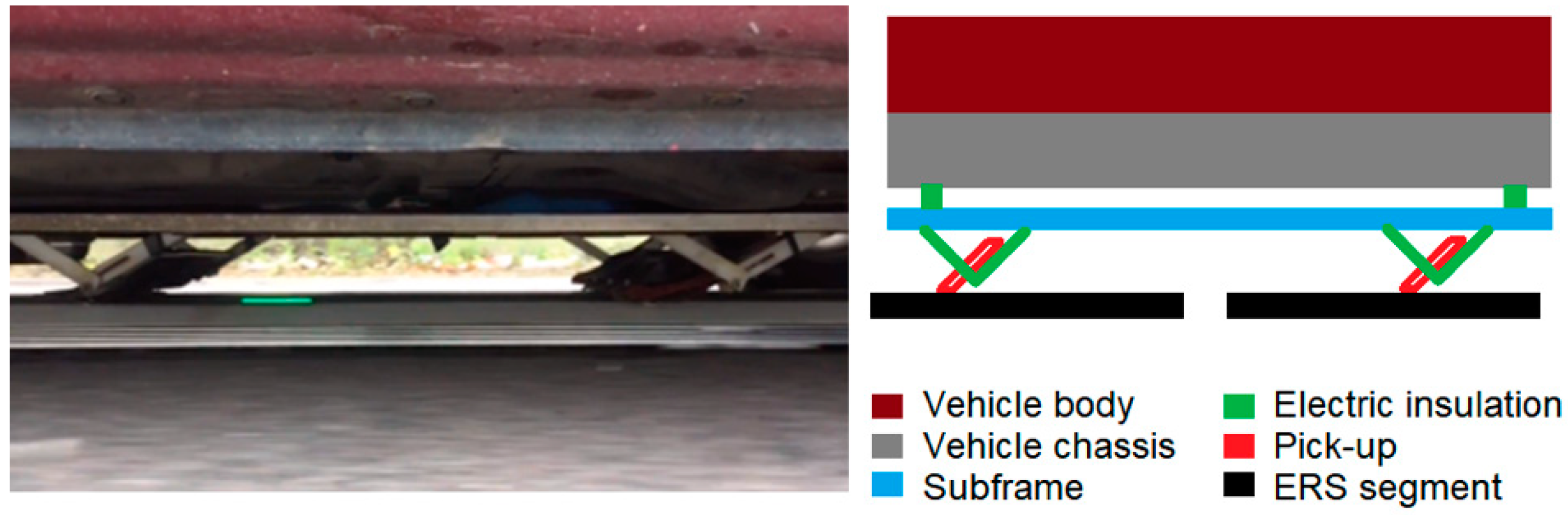
Three electrical domains exist in a vehicle suited for conductive ERS operation (see Figure 1). In normal operation conditions, these domains are isolated from one another: I) one domain is coupled to the high-voltage (HV) traction battery (like in normal BEVs), with a high impedance (commonly referred to as “floating”) with respect to both the vehicle’s chassis and the ERS power supply; II) one domain is coupled to the low-voltage (usually 12 or 24 V) system; and III) one domain is coupled to the ERS power supply, thus with a low impedance to its ground/earth potential.
The high-voltage traction battery domain is essentially the same as for BEVs. The HV traction battery supplies the main power electronic converter and the traction motor, as well as any other auxiliary devices that there could be.
The low-voltage domain is created from the previous one through an isolated DC–DC converter in order to power instrumentation, computers, lights, infotainment, etc., usually at 12 V but, in many heavy vehicles, at 24 V. The chassis may be used as the negative pole and conductor for this domain.
Finally, the ERS power supply domain is the part of the electric system on-board that is added in order to use the conductive ERS. It consists of the contact devices (“pick-ups”) interfacing the ERS and collecting the current from the ERS power supply lines, a rectifier (if needed), which is usually single-quadrant, to rectify the currents from the ERS, and an isolated DC–DC converter to transfer the energy to the HV traction battery domain. In most solutions, the pick-ups are mounted in a metallic sub-frame that is also electrically floating with respect to everything else, acting as a guard-rail for electric safety purposes.
The ERS can supply the vehicle acting as either an unregulated DC voltage source or a variable/AC source. In the first case, no rectifier is needed, and the pick-ups can be directly connected to the isolated DC–DC converter, transferring the electric power to the HV traction battery domain. The solutions implemented by Siemens (eHighways) or Alstom (APS) are examples of ERS with a DC supply [6,7].
However, some of the proposed technical implementations of conductive ERS feature a power supply that is not purely DC. In the Elways solution, the reported power supply is a bipolar AC (two sinusoidal waves of the same amplitude and frequency, phase shifted 180 degrees) [8,9], while in the Elonroad solution, the vehicle is connected to short segments that, as the vehicle moves, are alternatively connected to an unregulated DC voltage level (typically 600 V) or earth, resulting in a square-wave voltage signal at the pick-ups. The pick-ups provide at least three contact points reaching three consecutive power segments of 1 m each, every second of which is always at a near-zero voltage, while the rest are commutated between +600 V and zero [8,9]. Mostly because of the parasitic capacitances in the system, some of this square-wave voltage (at the input to the rectifier) is coupled to the vehicle chassis and body, which could potentially affect the performance of any chassis potential-monitoring device used. The chassis of the vehicle is, under normal conditions, also floating with respect to the external ERS power supply earth, only coupled through the parasitic resistance and capacitance of the tires and asphalt. However, since the ERS power supply is earthed, there is a risk that an insulation fault in this part of the electric system provides a low-impedance path to the vehicle chassis, creating a hazard for people outside the vehicle that could get in touch with the energized parts. Figure 1 shows a general schematic of the electric system onboard, representing the main components.
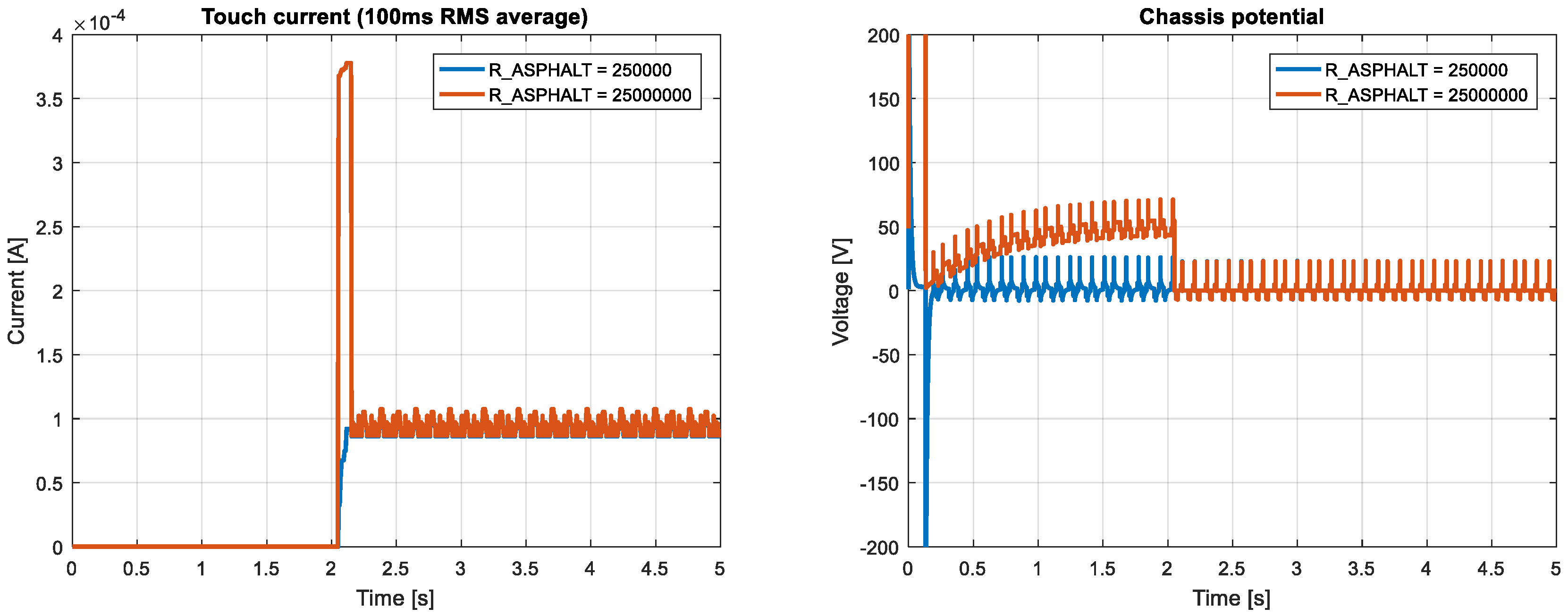
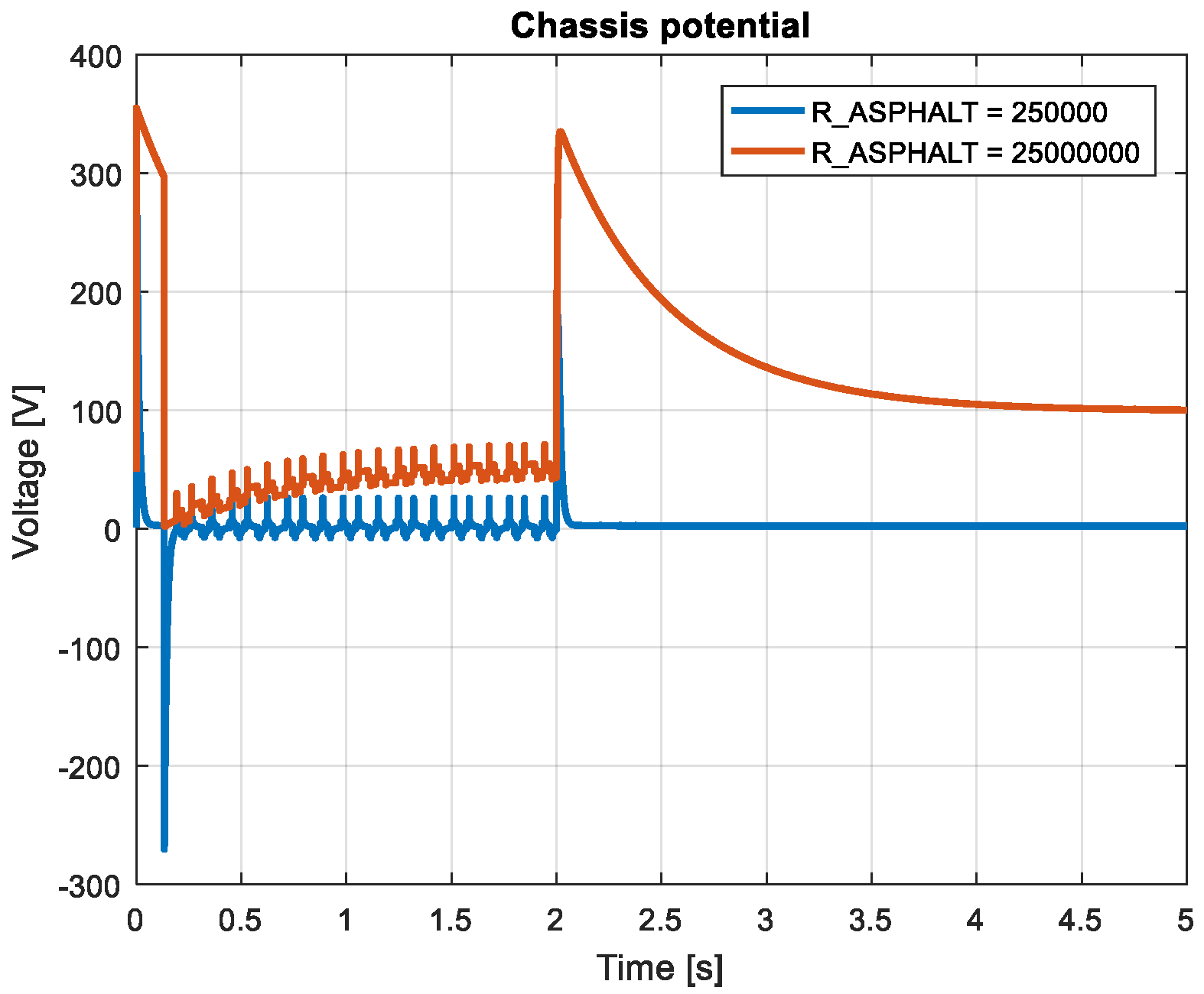
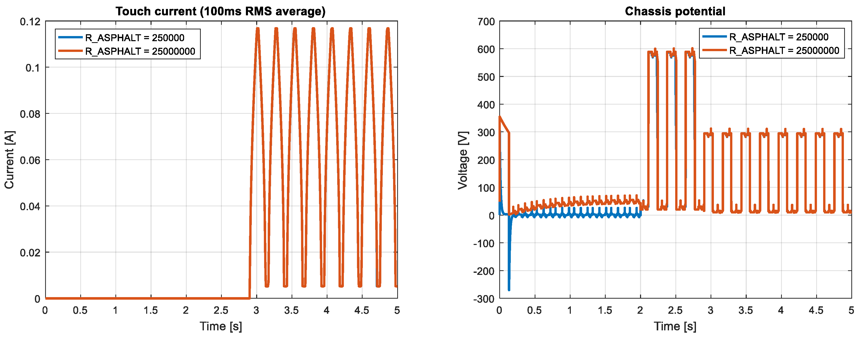
In order to simulate the effect of a human body in touch with the chassis of the vehicle, a resistor of 2.5 kΩ was placed between the vehicle chassis and the earth. The resistance value chosen was of course dependent on a number of factors: contact surface area, humidity conditions, type of shoes that the person is wearing (if any), etc. However, 2.5 kΩ seemed a reasonable value for this analysis, corresponding to very conservative assumptions from a safety point of view (e.g., a barefoot person standing on an earthed plate touching the vehicle with a whole hand). Since a relatively low value of resistance was assumed, the touch current was used to evaluate the potential hazard in different cases. On the basis of the charts published in [10,11] presenting different thresholds for perception, pain, and heart affection, the average root mean square (RMS) value of the touch current over 100 ms was used, and the safety limit was set to 5 mA.
All cases were simulated for an ERS supplying an AC square-wave voltage as in the Elonroad solution, since the authors had access to their pilot test-track to conduct experimental tests. In order to make the simulations as realistic as possible, some of the most critical parameters were measured directly in the test vehicle and trailer used at the Eloroad test site. The parameter values used for normal operation conditions are presented in Table 1.
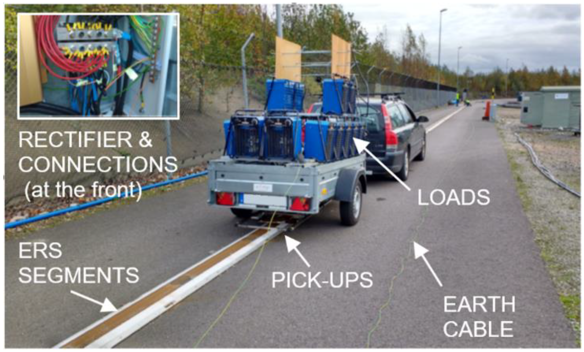
The experimental test setup consisted of a purposely built trailer equipped with three pick-ups installed on a sub-frame, as explained in the previous sections. The current from the pick-ups was rectified and consumed in a rack of industrial heaters mounted on the trailer, as seen in Figure 2.
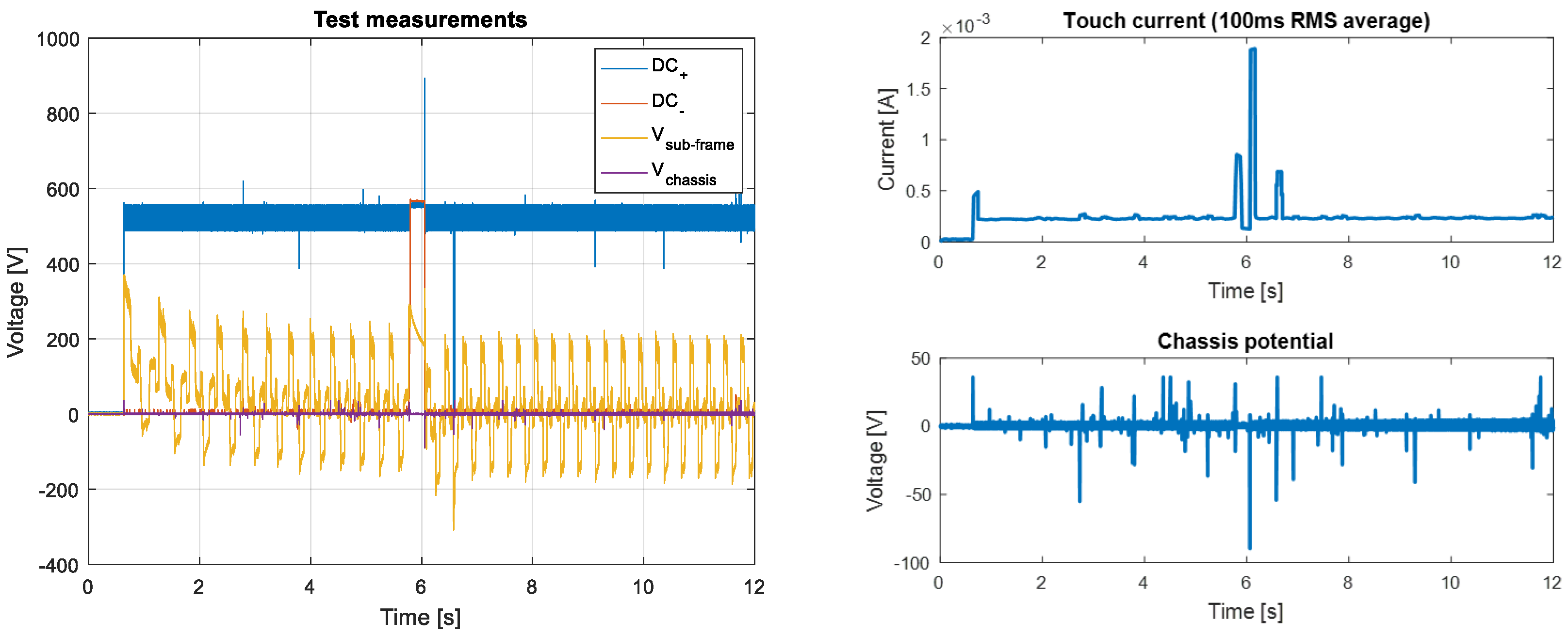
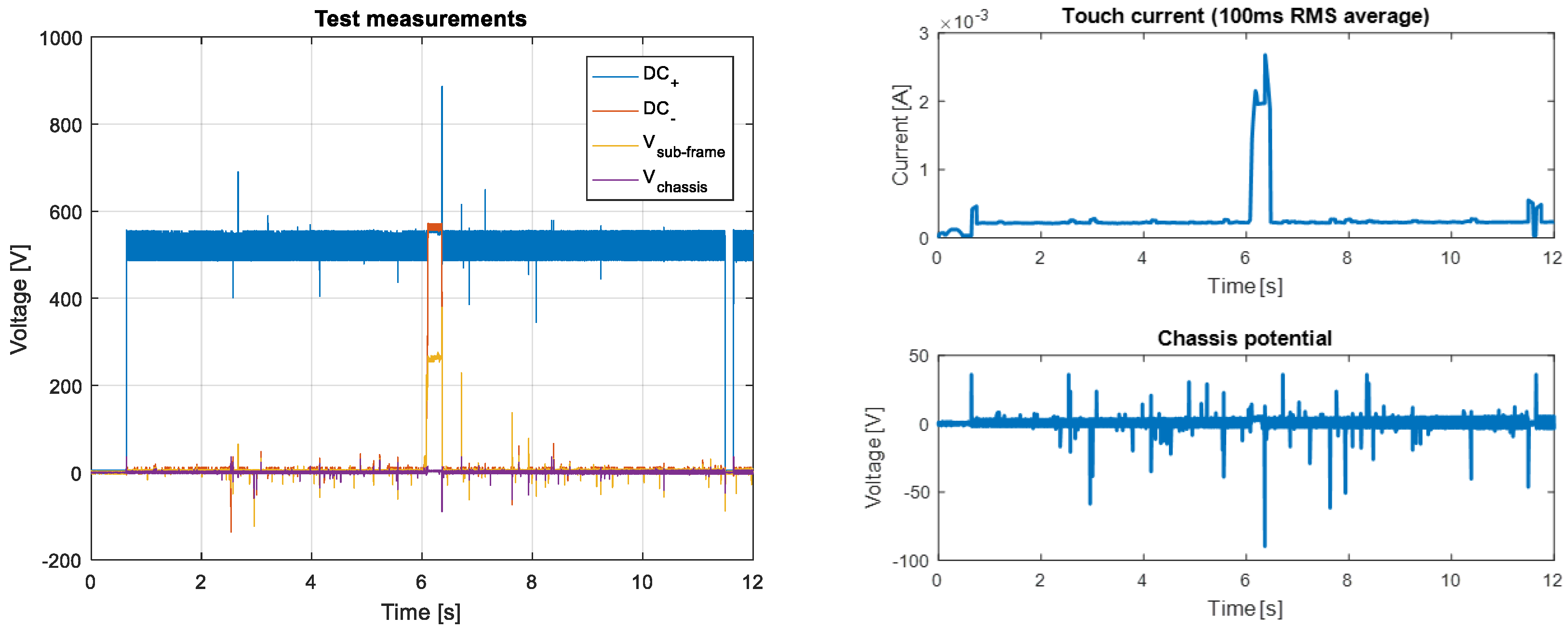
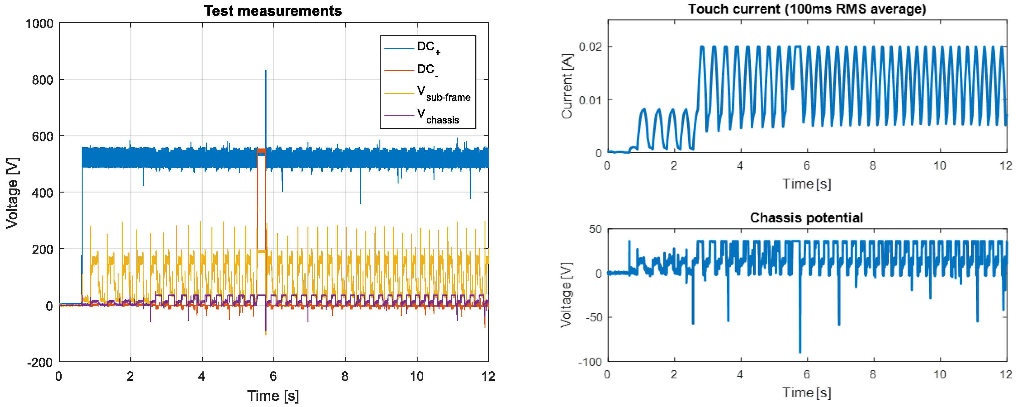
The voltages of the positive and negative terminal of the DC link at the rectifier output, together with the potential of the sub-frame (or guard-rail) and the earth potential (available through a long cable earthed at the rectifying station) were logged in every test, referred to the chassis potential. In addition, a 1.8 kΩ resistor was connected between the chassis of the vehicle and earth at all times, emulating a human body. This 1.8 kΩ resistor was readily available at the time of the experiments and therefore was chosen for the human body emulation despite being somewhat smaller than the one used in the simulations (2.5 kΩ) which, as stated before, already implied very conservative assumptions. The difference in human body resistance influenced the results to some extent; however, since there were uncertainties in several other parameters in the model (especially those due to parasitic effects), this difference was regarded as acceptable, and the experimental tests could be used to validate the model behaviour, at least qualitatively.

3. Results and Discussion

The results from the simulation model and the subsequent experimental validation are presented in this section.

3.1. Simulation Results

3.1.1. Normal Operation

In this case, a vehicle in normal operation (no insulation faults or any other kind of anomalies assumed) was simulated. The vehicle was driving over a conductive ERS at 30 km/h, and just before t = 2 seconds, a nearby person got in touch with the vehicle and remained in touch with it for the rest of the simulation. This is quite an unlikely event for a vehicle moving at that speed, but it helped to understand the simulation results better.
Two values were considered for the resistance of the asphalt layer, only affecting the current path through the tires, since the touch current went through a “human” path, modelled by a 2.5 kΩ resistor between chassis and ground, as previously stated.
The left plot in Figure 3 shows a moving, average, filtered touch current in a 100 ms RMS current window. The initial pulse at high asphalt impedance was due to the charge/discharge sequence of the parasitic capacitances in the system through the human body. From this plot, it is clear that a higher asphalt resistance resulted in higher touch current. This was because the return path through the tires and the asphalt had a higher resistivity, and, therefore, more current flew through the easy path, i.e., the human body. Looking at the right plot, we can see that once the model settled after the initialisation transient, the chassis potential stayed within reasonable levels. Once the human subject got in touch with the chassis, a lower resistance path to earth was established, and, therefore, the chassis potential was lowered.

3.1.2. Loss of Connection to the ERS Negative Rail

It is possible that, during operation, the vehicle loses contact to the negative rail of the ERS, which usually is grounded, and only the positive rail connection remains. In this case, due to the rectifier, the voltage at the negative terminal of the DC link just after the rectifier becomes the same as that at the positive terminal (approx. 600 V). To validate this, a vehicle driving on an ERS was simulated, losing the ERS negative rail connection at t = 2 s. The resulting chassis potential is shown in Figure 4.
No human touch was simulated, so the touch current was not relevant. However, it can be seen that when the negative rail connection was lost, the chassis potential increased drastically. The next simulation introduced a touch event 50 ms after the loss of the negative rail connection. Figure 5 shows both the filtered 100 ms RMS touch current and the chassis potential in that case.
As it can be seen in the left plot in Figure 5, in the unlikely event that a person in the vehicle surroundings touched the chassis just after a loss of connection to the ERS negative (earthed) rail, the touch currents became significantly higher than in the normal operation case. Although the maximum value of 5 mA was not exceeded, these results suggest that a loss of connection to the negative ERS rail should be detected by the vehicle, and safety measures should be taken in order to limit the chassis potential in that case.

3.1.3. Insulation Fault in the ERS Power Supply Domain

In this case, an insulation fault was introduced between one of the pick-ups and the vehicle’s chassis. It is worth noticing that this is an extremely unlikely event, since the mechanical design of the system with the guard-rail should prevent this from happening at all. Nevertheless, it was simulated since it poses one of the most potentially dangerous situations for conductive ERS vehicles.
The simulated insulation fault resistance was selected to be 2.5 kΩ (equal to the human body resistance), which is much higher than the value that could be expected if an alien metal object caused such fault. From the first plot in Figure 6, it is clear that, despite the relatively high fault resistance value chosen, the touch current was much higher than the safety value of 5 mA. This was to be expected nonetheless, since this is an extreme fault situation. In such cases, a safety system must be in place and, by sensing either the exceptionally high chassis potential—even before the touch event—or the leakage current through the body, detect the fault, bringing the chassis potential to a safe value and preventing any accidents.

3.2. Experimental Results

A first set of preliminary experimental measurements were conducted at the Elonroad pilot test site (see Figure 2) in order to validate the simulation model. The results are presented in this section.

3.2.1. Loss of Connection to the ERS Negative Rail

In this case, the trailer drove over the ERS under normal operation conditions (no insulation faults or any other kind of anomalies assumed) at a speed of 25–30 km/h and lost connection momentarily with the negative rail of the power supply at t = 5.8 s. Figure 7 shows all the measured signals—referred to earth for simplicity—as well as the touch current RMS value over 100 ms and the chassis potential alone.
Because of the different values of the resistors used to represent the human body and the dependence on the precise moment in which the connection was lost, the peak value of the touch current measured did not exactly match the one obtained in the simulations (see Figure 5). However, both the model and the measurements followed the same trend, and the corresponding touch current values were reasonably similar.

3.2.2. Loss of Connection to the ERS Negative Rail—Winter Conditions

In order to assess the operation under winter conditions, especially in cold climates where salt may be used to prevent ice formation on the road, the test in 3.2.1 was repeated after spraying a 1% salt water solution on the mechanical structures (electrically non-conductive) connecting the pick-ups to the sub-frame and the sub-frame to the vehicle’s chassis, shown in green in Figure 8. This salt solution effectively reduced the insulation resistance between the different electrical domains, and a higher amount of the AC voltage in the pick-ups and sub-frame was coupled to the chassis. Note that the voltage glitch at t = 2.3 s was not relevant for the test and could be neglected.
Looking at the results in Figure 9, it can be seen that the touch current in this case exceeded the 5 mA threshold due, mostly, to the reduced insulation resistance values and the rather pessimistic conditions assumed for the test. Nonetheless, a loss of connection to the ERS negative rail is considered “normal operation”, i.e., not representing any faulty condition; hence, it is desirable that the touch current values remain lower than 5 mA even for winter conditions.

3.2.3. Loss of Connection to the ERS Negative Rail—Winter Conditions with Guard-Rail Diodes

Since during normal operation there is always a pick-up connected to the negative rail of the ERS power supply (which is earthed at the rectifying station), by adding diodes from the sub-frame to the pick-ups, the potential of the sub-frame can be clamped to the negative ERS power supply rail at the connection point, avoiding that the parasitic capacitances in the system get charged.
Figure 10 shows the measurement results obtained if the previous test was repeated with these clamping diodes in place. As it can be seen from the upper right plot in Figure 10, after adding the clamping diodes between the sub-frame and the pick-ups, the value of the touch current was reduced, remaining below 5 mA even under winter operation conditions.

3.2.4. Insulation Fault in the ERS Power Supply Domain

In the last test case, an insulation fault was introduced between one of the pick-ups and the chassis, thus bypassing the sub-frame. For operational reasons, a rather large value of the fault resistance was chosen (22.5 kΩ). The obtained results are presented in Figure 11.
As discussed in Section 3.1.3, this could be one of the most critical safety challenges in conductive ERS powered vehicles, and even with the large fault resistance value employed, the touch current significantly exceeded the 5 mA threshold. Thus, an additional safety system is required to prevent any potential accident.

4. Conclusions and Future work

Conductive ERS technology appears as a promising solution for transport electrification. However, there are still a number of safety challenges that must be assessed. With the help of simulations and experimental measurements, this article analyses a number of potentially hazardous cases in which a too high chassis potential could result in dangerous touch current levels for people or animals around the vehicle.
Although both the models and the experimental measurements reflected the same trends and the obtained values were reasonably similar, further sensitivity analyses should be performed to evaluate the influence of the different model parameters in the final results.
Moreover, a new set of measurements is planned in order to complement the preliminary measurements presented in this article with additional fault cases and operating conditions.
Finally, an additional safety system must be developed and tested in the experimental setup, especially under the insulation fault cases.

Author Contributions

Formal analysis, F.J.M.-F. and L.L.; Funding acquisition, F.J.M.-F. and M.A.; Investigation, F.J.M.-F., S.S., and L.L.; Methodology, F.J.M.-F. and M.A.; Software, F.J.M.-F. and S.S.; Supervision, M.A.; Writing—original draft, F.J.M.-F.; Writing—review & editing, M.A.

Funding

This work was funded by the Swedish Electromobility Centre through the project “Power conversion challenges with an all-electric land transport system”.

Conflicts of Interest

The authors declare no conflict of interest.

References

  1. Taljegård, M.; Thorson, L.; Odenberger, M.; Johnsson, F. Electric road systems in Norway and Sweden. In Proceedings of the 2017 International Transport Electrification Conference and Expo ITEC Asia-Pacific, Harbin, China, 2–5 August 2017. [Google Scholar]
  2. Fyhr, P.; Domingues, G.; Andersson, M.; Márquez-Fernández, F.J.; Bängtsson, H.; Alaküla, M. Electric Roads: Reducing the societal cost of automotive electrification. In Proceedings of the 2017 International Transport Electrification Conference and Expo ITEC, Chicago, IL, USA, 22–24 June 2017. [Google Scholar]
  3. Márquez-Fernández, F.J.; Domingues, G.; Lindgren, L.; Alaküla, M. Electric Roads: The importance of sharing the infrastructure among different vehicle types. In Proceedings of the 2017 International Transport Electrification Conference and Expo ITEC Asia-Pacific, Harbin, China, 2–5 August 2017. [Google Scholar]
  4. Government of Sweden. Innovation and Cooperation for a Sustainable Future—A German & Swedish Partnership for Innovation. January 2017. Available online: https://www.government.se/490ab0/contentassets/a1b5e6fbe60c4154a9a402d25343e26f/innovation-and-cooperation-for-a-sustainable-future.pdf (accessed on 8 May 2019).
  5. Government of Sweden. A French and Swedish Strategic Partnership for Innovation and Green Solutions—Roadmap. November 2017. Available online: https://www.government.se/4ac905/contentassets/94aa2209382846a187f02bac9325815e/171115-roadmap-partenariat-frse-innovation-verte-2017-final-en-version.pdf (accessed on 8 May 2019).
  6. Siemens eHighway. Available online: http://w3.siemens.com/topics/global/en/electromobility/Pages/ehighway.aspx (accessed on 28 April 2017).
  7. Veyrunes, P.; Duprat, P.; Hourtane, J.L. Ground-level feeding systems: From rail to road. In Proceedings of the International Transport Electrification Conference and Expo ITEC Asia-Pacific 2017, Harbin, China, 2–5 August 2017. [Google Scholar]
  8. Alaküla, M.; Márquez-Fernández, F.J. Dynamic charging solutions in Sweden: An overview. In Proceedings of the International Transport Electrification Conference and Expo ITEC Asia-Pacific 2017, Harbin, China, 2–5 August 2017. [Google Scholar]
  9. Suul, J.A.; Guidi, G. Technology for Dynamic On-Road Power Transfer to Electric Vehicles, Technical Report EU Project ELinGO—Electric Infrastructure for Goods Transport. Available online: https://www.sintef.no/globalassets/project/elingo/18-0733---rapport-3---technology-for-dynamic-on-road----6-til-nett.pdf (accessed on 8 May 2019).
  10. IEC TS 60479-1. Effects of Current on Human Beings and Livestock—Part 1: General Aspects, 4th ed.; International Electrotechnical Commission: Geneva, Switzerland, 2005. [Google Scholar]
  11. IEC TS 60479-2. Effects of Current on Human Beings and Livestock—Part 2: Special Aspects, 3rd ed.; International Electrotechnical Commission: Geneva, Switzerland, 2007. [Google Scholar]
Figure 1. General system’s schematic.
Wevj 10 00030 g001
Figure 2. Experimental setup at the Elonroad pilot test site.
Wevj 10 00030 g002
Figure 3. Touch current (100 ms RMS average) (left) and chassis potential (right) during normal operation.
Wevj 10 00030 g003
Figure 4. Chassis potential under negative rail connection loss.
Wevj 10 00030 g004
Figure 5. Touch current (100 ms RMS average) (left) and chassis potential (right) under negative rail connection loss (at t = 2s) and touch event (at t = 2.05s).
Wevj 10 00030 g005
Figure 6. Touch current (100 ms RMS average) (left) and chassis potential (right) under pick-up to chassis insulation fault (at t = 2s) and touch event (at t = 2.90s).
Wevj 10 00030 g006
Figure 7. Measured voltages referred to earth (left), touch current RMS value over 100 ms (right, top), and chassis potential (right, bottom) under a loss of connection to the negative rail.
Wevj 10 00030 g007
Figure 8. Real pick-up installation on a test vehicle (left) and concept drawing identifying the main components (right).
Wevj 10 00030 g008
Figure 9. Measured voltages referred to earth (left), touch current RMS value over 100 ms (right, top), and chassis potential (right, bottom) under a loss of connection to the negative rail in winter conditions.
Wevj 10 00030 g009
Figure 10. Measured voltages referred to earth (left), touch current RMS value over 100 ms (right, top), and chassis potential (left, bottom) under a loss of connection to the negative rail in winter conditions with guard-rail clamping diodes.
Wevj 10 00030 g010
Figure 11. Measured voltages referred to earth (left), touch current RMS value over 100 ms (right, top), and chassis potential (right, bottom) under a pick-up-to-chassis insulation fault.
Wevj 10 00030 g011
Table 1. Model parameters. ERS: electric road systems.
ParameterValueUnits
DC voltage level from ERS600V
Power supplied by ERS100kW
Resistance of the return path of the current (negative rail)0.06Ω
Resistance of the DC negative rail connection to earth0.01Ω
Insulation resistance between DC link terminals (ERS supply side) and chassis260
Parasitic capacitance between DC link terminals (ERS supply side) and chassis24nF
Insulation resistance between chassis and guard-rail200
Parasitic capacitance between chassis and guard-rail56pF
Insulation resistance between pick-ups and guard-rail17
Parasitic capacitance between pick-ups and guard-rail0.32nF
Resistance of the tires (chassis–asphalt)0.25
Resistance of the asphalt layer0.25
Parasitic capacitance of the tires87pF
Parasitic coupling isolated DC/DC converter (+ and −sides)44pF

