1. Introduction
The anticipated sixth generation of wireless communication technology, 6G, represents a paradigm shift in connectivity, aiming to surpass the capabilities of its predecessor, 5G. Envisioned as a transforming force, 6G seeks to provide ultra-fast data rates, incredibly low latency, and unparalleled connectivity, fostering innovations that extend beyond conventional wireless communication boundaries [
1]. The technology envisions a seamless integration of diverse communication paradigms, including terahertz frequencies, new waveforms, edge computing, holographic communications, and advanced artificial intelligence [
2]. The overarching goal is to create an ecosystem where connectivity is not just pervasive but also intelligent and adaptive to the diverse needs of users. In the pursuit of 6G, the emphasis on continuous innovation becomes paramount. The optimization of resources, efficient spectrum utilization, and sustainable practices are integral aspects that drive the evolution of 6G. Embracing innovation is crucial not only for achieving unprecedented levels of performance but also for addressing the evolving demands of a connected world, ensuring that technological advancements contribute to a more resource-efficient and sustainable future.
In that context, the terahertz (THz) band emerges as a promising domain with its vast bandwidth and exceptionally high data rates [
3], offering robust support for diverse 6G applications, including wireless data centers [
4], ultra-short-distance communications, and other novel scenarios. Optical wireless communications (OWCs) harness various bands within the optical spectrum, comprising infrared (IR), visible light, and ultraviolet (UV) bands, presenting nearly thousands of terahertz of untapped spectral resources. Notably, the visible light band shows several merits, including its eco-friendliness, cost-effectiveness, freedom from spectrum regulation, heightened security, and immunity to electromagnetic interference [
5,
6]. Particularly in settings where radio frequency (RF) communications encounter limitations, OWCs demonstrate substantial application potential, giving rise to a range of optical communication technologies such as visible light communications (VLC), light fidelity (Li-Fi), optical camera communications (OCC), free space optical (FSO) communications, and light detection and ranging (LiDAR), all being more than relevant for 6G.
In the pursuit of 6G technologies, it is imperative to recognize that not all applications demand ultra-high data rates but mainly robustness. In that context, considerations for IoT applications, dedicated industrial use cases, and certain vehicular communications underscore the importance of diverse communication solutions. VLC emerges as a pertinent technology [
7]. Unlike bandwidth-intensive applications, VLC offers a balanced and resource-efficient approach for different types of scenarios. Integrating VLC into the portfolio of 6G technologies holds particular relevance for smart cities and industries. Its adaptability, low power consumption, and suitability for specific use cases align seamlessly with the varied communication needs in urban environments and industrial settings. By acknowledging the nuanced requirements of different applications, 6G can position itself as a holistic and inclusive technological ecosystem where innovations like VLC contribute to the optimization of resources and the realization of a technologically advanced yet tailored connectivity landscape.
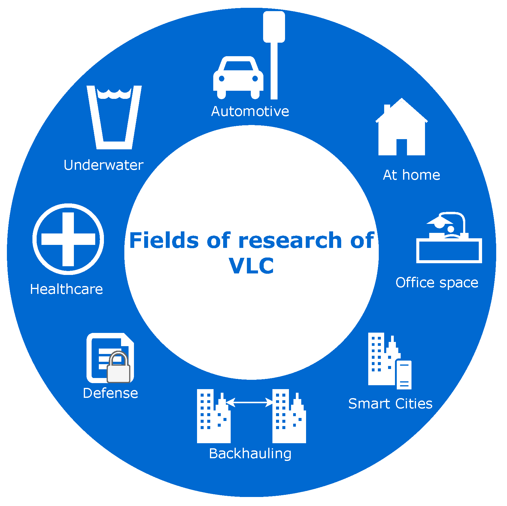
The potential applications of visible light communication (VLC) within the 6G technology landscape are diverse and strategically aligned with the demands of contemporary urban and industrial scenarios, as depicted in
Figure 1. Each sector, starting with automotive, exemplifies the adaptability of VLC to meet specific communication needs. In the automotive domain, VLC can leverage LED headlights for vehicle-to-vehicle (V2V) communication, facilitating short warnings and creating communication daisy chains in heavy traffic conditions [
8]. Similarly, private and office spaces benefit from consumer-oriented Li-Fi products, offering internet connectivity through visible or infrared lights [
9]. Smart cities stand to gain from VLC’s capacity to relieve RF spectrum usage outdoors, providing alternative communication for local, line-of-sight, and short-distance applications [
10]. The smart industry sector, including factory automation and logistics, witnesses the potential of VLC in optimizing wireless connectivity within industrial warehouses [
11]. Deploying free space optical (FSO) communication as a backhauling system in cities characterized by towering skyscrapers offers a high-capacity and wireless solution for data transmission across urban landscapes [
12,
13]. The military sector explores the secure, non wall-penetrating nature of VLC, potentially replacing wired communication means for local applications [
14]. Healthcare applications leverage VLC for remote health monitoring, aligning with smart health strategies in smart cities [
15]. Finally, underwater communication, a traditionally challenging domain, sees VLC’s potential to achieve communications in harsh turbulent conditions [
16]. This paper critically analyzes and provides the essential tools for integrating VLC communication in short-distance scenarios within urban and industrial settings, contributing to the dynamic landscape of 6G technologies.
In the evolution from 5G to 6G, the incorporation of novel waveforms emerges as a pivotal consideration. While 5G’s development was encumbered by material limitations, 6G signifies a phase of unconstrained exploration. A central tenet of 6G’s objectives lies in augmenting spectral throughput, particularly for IoT applications. This trajectory may initiate with a transition from the prevailing orthogonal frequency-division multiplexing (OFDM) standards, thereby paving the path for potential migration towards universal filtered multi carrier (UFMC) for enhanced efficiency. Indeed, UFMC has several benefits for 6G applications. UFMC has better spectral efficiency, lower sensitivity to synchronization errors (compared to OFDM) [
17], can be resilient to the Doppler effect in some cases [
18], which is relevant for applications with mobility, and finally, has more flexibility in the filters used for pulse-shaping [
19]. Taking into account the advantages of VLC and its growing interest for 6G combined with the promising future of UFMC for 6G, combining both seems a relevant study. To summarize, this paper presents the combination of VLC, which is a technology that has been foreseen as promising for 6G among optical wireless communication technologies [
20], and UFMC.
This study delves into the strategic utilization of visible light communication (VLC) as a means of short-range communication within urban and industrial environments. By concentrating on scenarios where ultra-high data rates are non-essential, the investigation explores VLC’s pragmatic applications in optimizing communication resources.The prior research, such as studies examining VLC’s efficacy in industrial automation or urban infrastructure monitoring, furnishes invaluable insights [
21]. This study advances this domain by proposing a methodology for calculating indoor and outdoor VLC channels, augmenting the existing body of knowledge. Additionally, it offers a comprehensive suite of open-source tools for designing and simulating VLC scenarios, accessible via the Github platform. Leveraging these resources, the study advocates for simulating VLC communications in a tailored smart city scenario using the UFMC waveform, assessing performance metrics such as bit error rate and spectral efficiency. The promising outcomes position UFMC-VLC technology as a prospective component of future 6G systems. Through this endeavor, the study seeks to expedite the integration of VLC within the broader spectrum of 6G technologies, fostering an adaptive framework conducive to smart city and industrial applications.
The study begins by establishing the relevance of VLC as a communication resource for scenarios where ultra-high data rates are not paramount. Emphasizing the significance of diverse communication solutions, the paper positions VLC as a tailored and efficient option for specific applications within smart cities and industries. Subsequently, attention is directed towards the introduction of an open-source simulator designed to provide researchers with fundamental tools for designing and simulating VLC scenarios. The simulator serves as a versatile platform, enabling the modeling and analysis of VLC communication systems in various urban and industrial environments. The paper then presents insightful results derived from simulations using innovative modulation schemes such as UFMC, a general and enhanced version of OFDM, showcasing the practicality and efficacy of integrating VLC in short-distance communications. Finally, a concluding section synthesizes the findings, emphasizing the role of VLC within the 6G landscape, and underscores the importance of continued exploration and innovation in optimizing communication resources for diverse applications in urban and industrial domains.
2. Materials and Methods
In the realm of visible light communication (VLC), even in outdoor environments, the optical power propagation from emitter to receiver is profoundly influenced by the specific scenario. Given that VLC operates with light, obstacles pose a significant challenge, acting as disruptors to communication. Additionally, reflections in the environment can have varying effects, either adding up constructively to the signal or introducing noise-like contribution at the receiver [
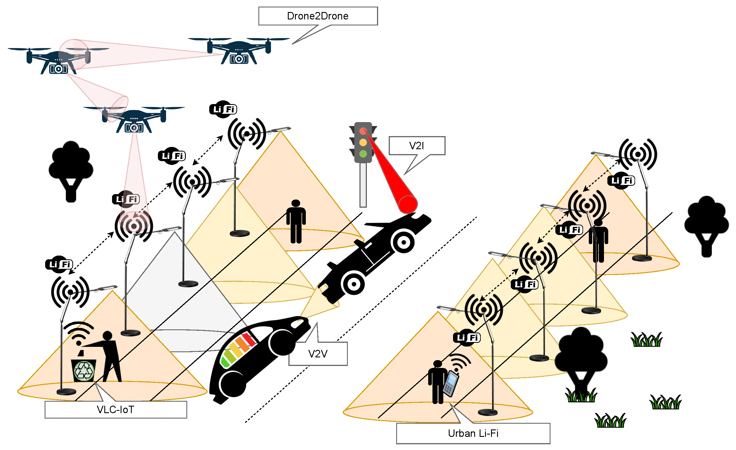
22]. Recognizing these factors, smart city applications capitalizing on VLC could strategically align with scenarios where these requirements are inherently met, where there is mainly line of sight (LoS). This is particularly possible and advantageous for applications such as IoT, urban Li-Fi or OCC, vehicle-to-vehicle (V2V) communication, vehicle-to-infrastructure (V2I) communication, communication among drones, and various supplementary scenarios illustrated in
Figure 2.
Moving beyond the scenario considerations, it is essential to understand that while VLC utilizes LEDs for communication, the diversity of LEDs introduces a range of parameters within the emitter itself. Each LED functions akin to an antenna, possessing a distinct radiation pattern that delineates how the power consumed by the LED is distributed through space in an angular manner [
23]. Notably, LEDs employed in different applications exhibit unique radiation patterns. For instance, LEDs designed for indoor lighting, also called Lambertian emitters, disperse light evenly in the room [
24], while car headlights, street lights, and industrial lighting each carry their distinctive angular radiation signatures [
21,
25].
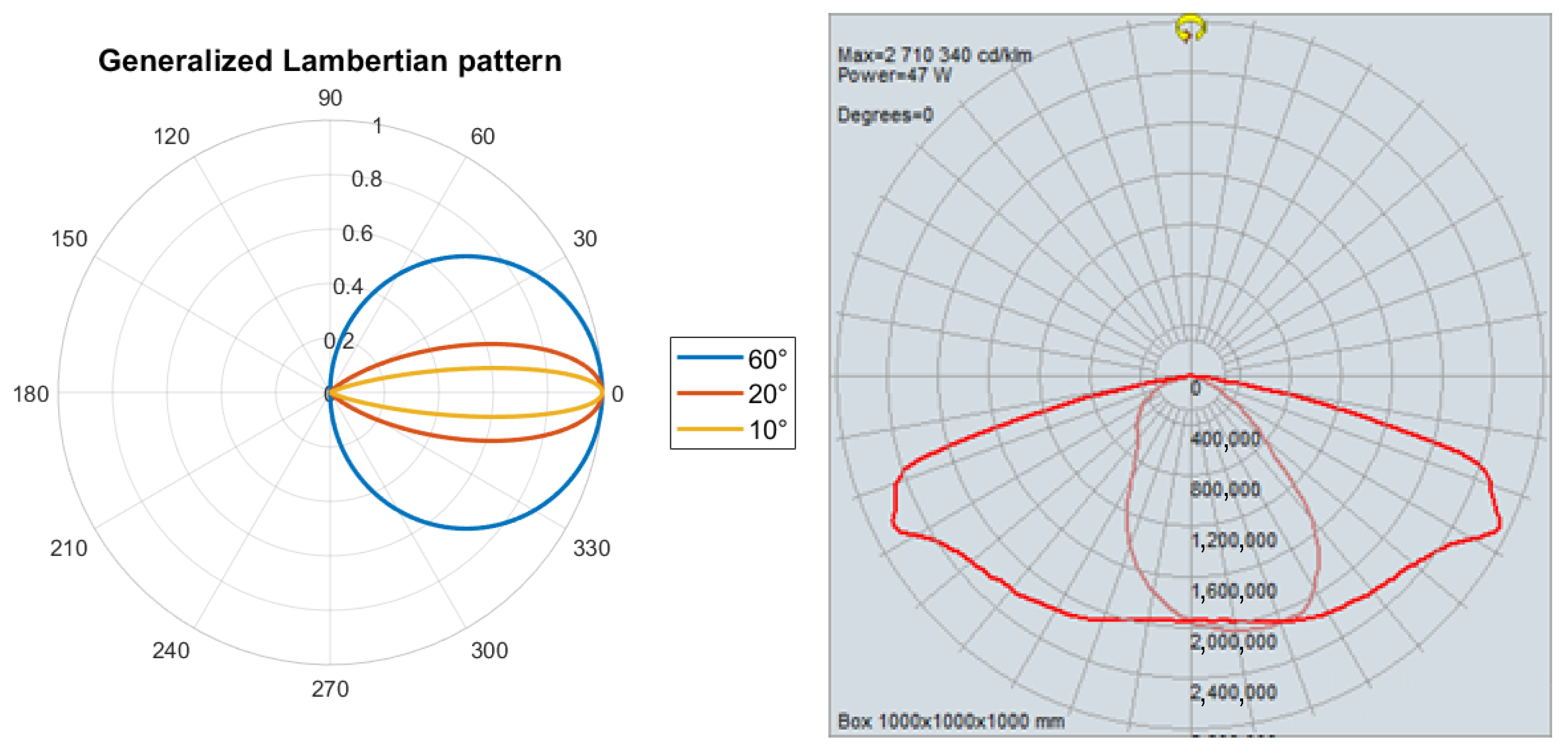
Figure 3 shows a plane representation of the radiation pattern of a Lambertian emitter for three different half power angles (on the left side of the figure) and a NIKKON streetlight (on the right side of the figure). A Lambertian emitter has a uniaxial symmetry to the radiation pattern and its half-power angle parameter gives it directionality. Two perpendicular planes of the streetlight 3-D radiation pattern are represented on the right side of the figure. It can be seen that there is no axial symmetry and a preferred direction in the radiation of light power.
This paper underscores the nuanced interplay between the materials employed in visible light communication (VLC) systems, the configuration setup, and the surrounding environment. Recognizing the distinctiveness of each LED and its crucial positioning relative to the receiver in diverse scenarios, this paper introduces a simulator designed to empower end users to define these pivotal parameters. In its primary phase, the simulator allows users to intricately characterize the LED properties and spatial arrangement, considering the unique features of each light emitter. Additionally, it facilitates the assessment of communication performance under an innovative modulation scheme, UFMC. Notably, the simulator, also meant for outdoor communication, extends its functionality relative to the baseline literature to incorporate environmental factors, allowing users to specify the quantity of particles in the air and consequently identify optical power loss attributable to atmospheric presence. While a more comprehensive exploration of these atmospheric effects can be found in our earlier work [
21], this paper concentrates on highlighting the simulator’s versatility and the pertinence of VLC within the 6G paradigm.
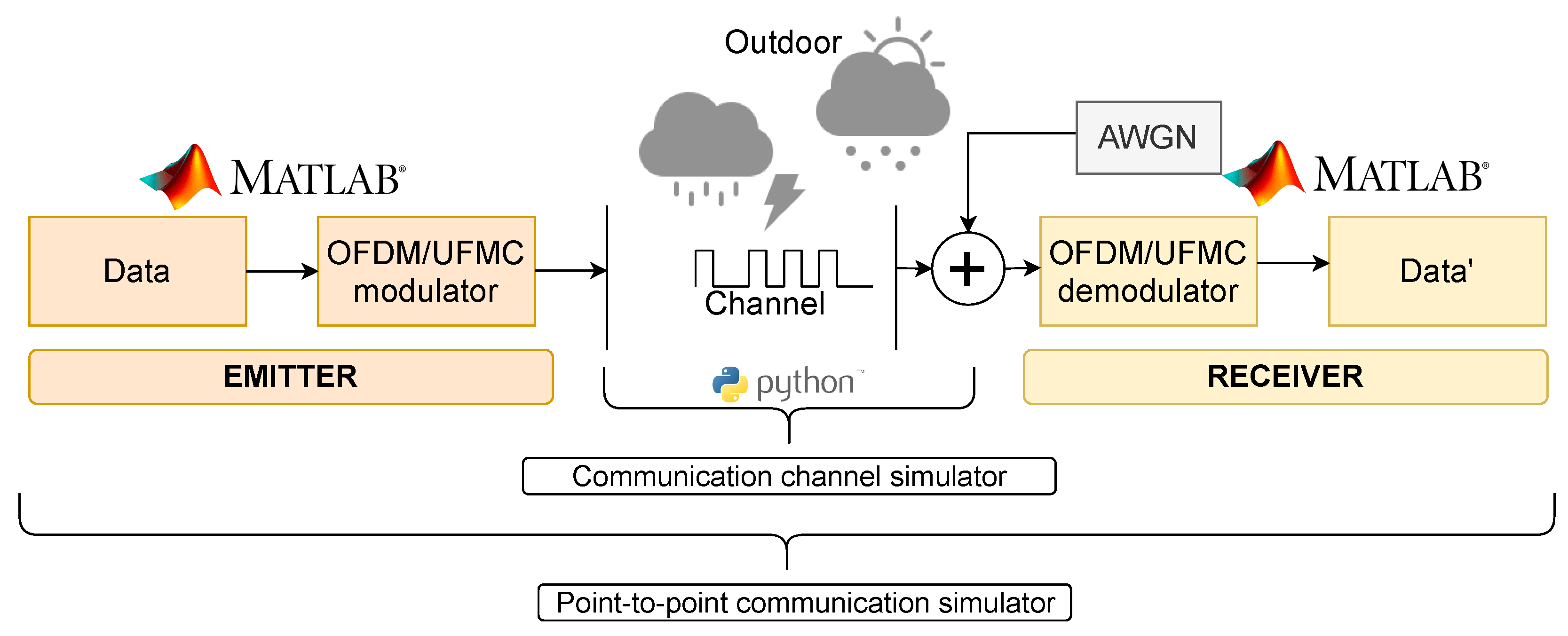
Figure 4 shows how both simulators work together to study a scenario. The MATLAB simulator focuses on generating the point-to-point communication data stream, and the Python channel simulator takes into account the path loss computation of the communication. The two combined give us communication performance metrics of a point in space in a scenario.
The subsequent section delineates the simulator’s key features and presents the primary outcomes obtained while employing the UFMC modulation scheme in regards to OFDM performance.
2.1. The Channel Simulator
The material employed in this study comprises a communication channel simulator crafted using Python. Initially, the foundation for this simulator drew inspiration from a primary version based on MATLAB, as documented in reference [
27]. Our improved Python simulator not only operates on an open-source platform but also brings novel simulation parameters. These enhancements encompass the introduction of an innovative smoke model, the integration of 3-D graphical representations, increased flexibility for customizing simulation “room” parameters or outdoor configuration, and the consideration of authentic lamp radiation patterns.
The channel simulator presented in this study can be found on Github [
28]. It empowers users to incorporate radiation measurements provided by light fixture manufacturers, typically available in formats such as the redIlluminating Engineering Society (IES) or EULUMDAT [
29]. These files encompass comprehensive information about the light fixture, its characteristics, and the associated radiation pattern. Users can integrate these data into the simulator for precise simulation in each specific situation, enhancing the accuracy and realism of VLC performance assessments. The simulator has, for example, been applied in various smart city or concrete industrial use cases in the past [
21].
The present simulator is an enhanced version of our previous work where the communication simulator was upgraded to include several modulation schemes such as orthogonal frequency division multiplexing (OFDM) and universal frequency multi carrier (UFMC), together with the introduction of performance measures.
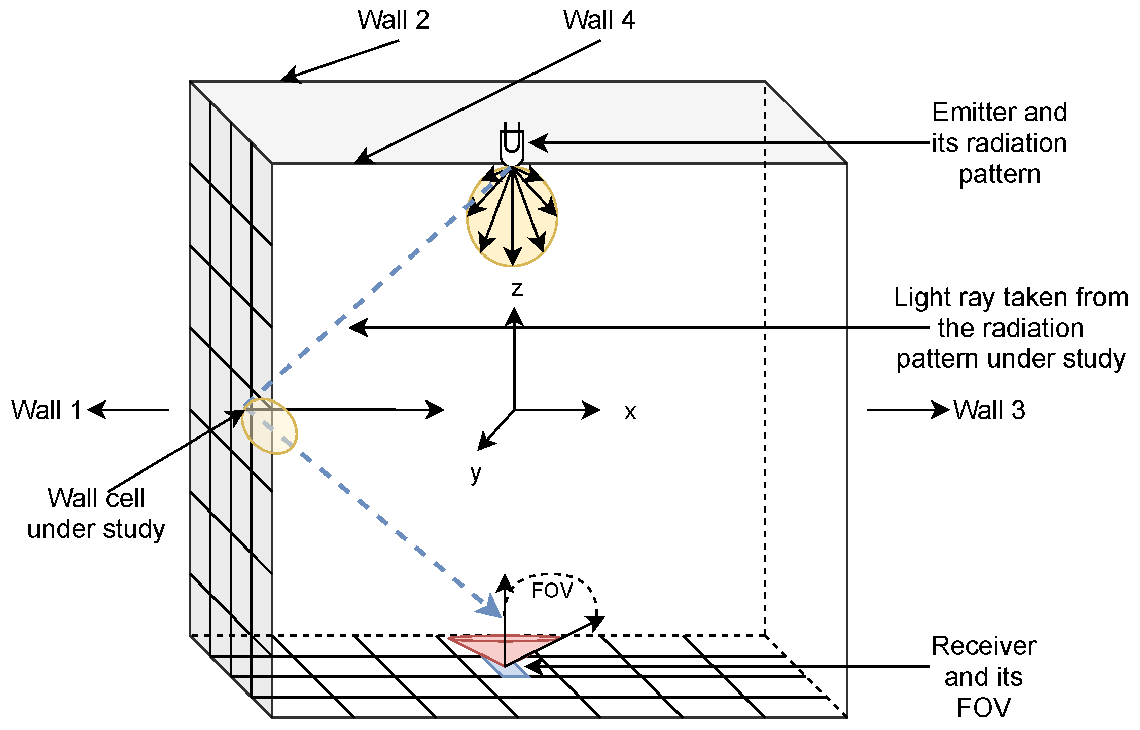
Figure 5 explains the simulated environment and the basic principle of the simulator. The aim of the simulator is to assess the optical power distribution of a VLC system in a scenario under study. To do so, the software creates first a virtual three-dimensional room where the axes’ origin is in the center. Here, the light is in the center of the ceiling, and the reception plane is located at the same distance from the origin as the emitter but in the negative application of the Cartesian coordinate system. Then, several parameters can be set such as the presence of walls or not, their reflection coefficients, and the position of the emitter in the virtual room. Afterward, the reception plane where the communication coverage needs to be assessed is set. It should be noted that the tilting of the emitting light or receiver is not taken into account. As mentioned before, only the scenarios that can benefit from a major part of LoS are considered here. The walls are subdivided into a matrix of unit surfaces to assess the quantity of power coming from the LED and then acts as a Lambertian point source. The ground being also subdivided in unit cells enables the computation of the portion of optical power reaching the receiver at each cell of the receiver’s plane cell.
In the scope of this paper, a scenario where a light source is hanging on a wall was chosen to study the performances of the UFMC modulation scheme.
Figure 6 shows (left) the setup under study where the light source is enlightening the pedestrian under it and its connected device, as well as (middle and right) the resulting optical power coverage map. To be as close to reality as possible, a 47 W streetlight NIKKON MURAS with a light temperature of 4000 K was selected. Its corresponding IES file was obtained from the Lumsearch website, as referenced in [
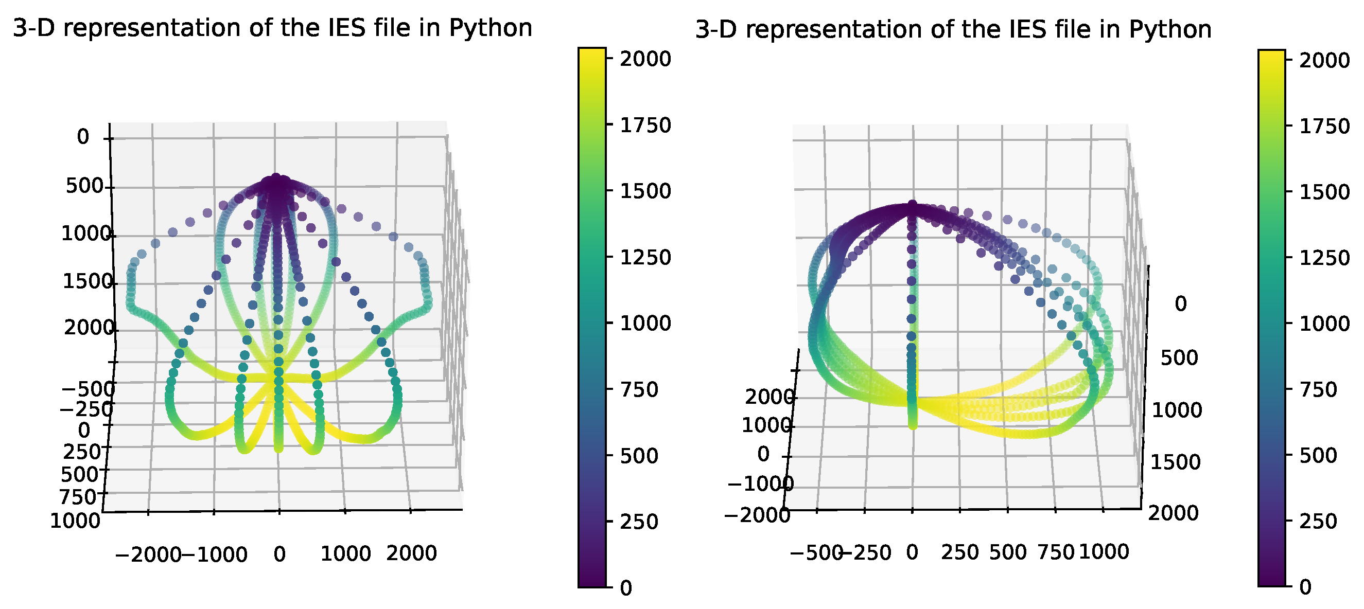
26]. This file contains the light’s name and radiation pattern, defined by a table using the two angles C and Gamma. The IES file encompasses data for 13 azimuth angles (ranging from 0 to 360 degrees with a 30-degree interval) and 181 elevation angles (ranging from 0 to 180 degrees with a 1-degree increment). The luminous flux value per solid angle (measured in candela or lumens per steradian) is provided for each pair of angles to construct the radiation pattern. Its radiation pattern is represented in
Figure 7. The non-axial symmetry is clearly visible.
Due to the power map (right side of
Figure 6), it is possible to choose a location in space where the UFMC performance should be quantified. For a user positioned under a streetlight of 6 m high with the end-device at a height of 1.5 m, the signal is the strongest at the closest point to the streetlight as opposed to the corner of the space under study. The coordinate with the strongest optical power and the two coordinates with the weakest optical power are represented in
Figure 6. In the remainder of this paper, we assume that the user is located at the ideal location.
2.2. The Communication Simulator
Now that the point in space where the UFMC performance is studied is set, the communication channel simulator gives the information of the amount of optical power received and can also give us the information about the channel’s impulse response (CIR). The CIR is a key parameter to assess the available coherence bandwidth and is defined according to the delay between the LoS main peak (the first ray reaching the receiver) and the second peak (the reflected ray on a wall) reaching the receiver. Given that the light wave travels at the speed of light, and the measures of the scenario, if the LoS ray of light arrives at a time of
and the first reflection (due to the proximity of the wall to the light) is approximately
, the difference between both rays, the main signal and its reflection, gives place to a bandwidth of approximately 3000 MHz, which is more than enough for the envisioned scenario (See Equation (
1)). Thus, the available coherence bandwidth is sufficient to apply the flat channel hypothesis.
Furthermore, OFDM for VLC has been standardized in ITU G.9991 standard [
30], and the framework of this standard was chosen in this paper to generate the waveforms. The standard proposes a set of parameters for bandwidths of 50, 100, or 200 MHz, which fit our scenario well given the available bandwidth computed above. Using the parameters of the G.9991 standard chosen is thus consistent.
A point-to-point communication simulator as illustrated in
Figure 4 is used in this study. Both OFDM and UFMC modulation schemes are implemented in this simulator to estimate the system’s performance in terms of bit error rate (BER) and spectral efficiency (bit/s/Hz). The paper’s use of OFDM simulation is interesting, especially as it is widely standardized. What sets it apart is comparing OFDM with UFMC, a 5G candidate waveform that was not selected. Furthermore, the inclusion of a realistic lamp pattern adds originality to the study. This section highlights the key parameters for OFDM and UFMC that were studied. On top of the use of UFMC, the originality of this study is the use of realistic LED optical spatial distributions and real photodiode models in the scenario under study. The rest of this section describes the working principles of UFMC and how to generate a VLC compatible signal, namely, a real-valued and positive signal. It then presents the various key parameters used in the simulation.
2.2.1. UFMC Principles
Figure 8 shows the functional blocs of UFMC adapted to VLC. As OFDM has widely been studied and standardized, its working principles are not reiterated in this paper. The interested reader can find information about it at the following reference [
31]. The input data of UFMC are also complex symbols resulting from an IQ in-phase and quadrature (IQ) symbol mapping method just like OFDM. In UFMC, the total bandwidth is first divided into B sub-bands. The filtering operation in UFMC is carried out per sub-band (cf
Figure 8). The data from each sub-band undergo an IFFT operation, and the Chebyshev filter (of length
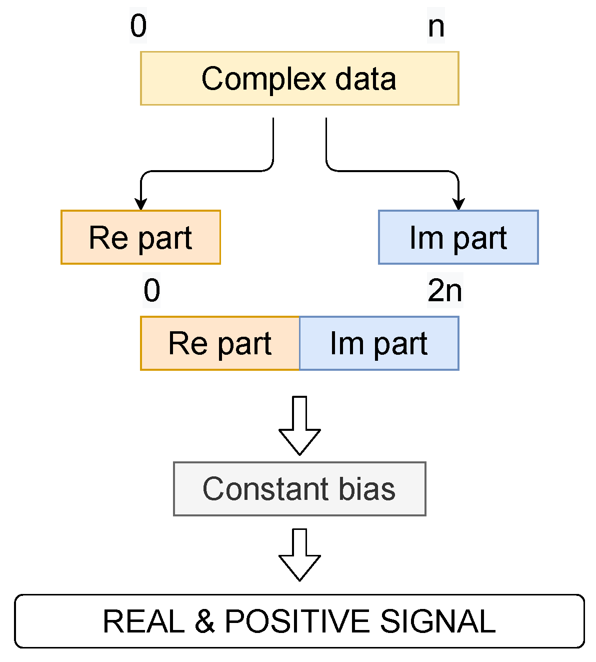
L) is applied in the time domain on each sub-band. To be compatible with VLC, OFDM uses the Hermitian symmetry (HS) property to make it real-valued by making the data symbols transmitted on positive frequencies the complex conjugates of those on negative frequencies. As opposed to OFDM, it is more difficult to apply the HS to UFMC signals to make it a real-valued signal. Since the filter stage is after the IFFT, it does not make sense to add HS as in OFDM. Adding an extra IFFT stage before sending on the transmission channel does not solve the problem either. Therefore, a juxtaposition method is used instead to have a real-valued signal HS-free UFMC signal, as suggested in [
32] (cf
Figure 9). A zero-padding technique is applied on each received symbol of length (
) at the receiver side to reach a sample number equal to twice (
) the subcarrier number
N used at the emission. This operation is followed by the FFT and the down-sampling technique for data recovery.
The OFDM and UFMC data are generated thanks to a MATLAB program that can also be found in our Github [
28]. The constraint of the VLC technology is using a real and positive signal to modulate the LED’s current. This implies that the two modulations, developed in the framework of RF transmission, require adequate changes to fulfill these constraints. The juxtaposition method has been chosen to have a real-valued signal, and a constant bias is added to have a positive-valued signal. The juxtaposition method consists of generating a conventional complex signal (OFDM or UFMC) and juxtaposing all the real parts and all the imaginary parts of the complex numbers forming the desired symbols in the time domain to obtain a real-valued signal. The mechanism of juxtaposition is illustrated in
Figure 9.
2.2.2. Key Parameters for the Simulations
The parameters that OFDM and UFMC modulations have in common are the number of bits per subcarrier
m, the number of subcarriers
N, the total number of symbols generated for the simulations
, and the number of bits coded per subcarrier
. In this paper, several sizes of QAM modulation were used to encode bits. They are the 2-QAM (also called binary phase shift keying (BPSK)), 4-QAM (also called quadrature phase shift keying (QPSK)) and 16-QAM. For OFDM, the size of the guard interval (GI) is often proportional to
N. Logically, the important parameters of the UFMC scheme are the number of sub-bands
(B
th filter in
Figure 8), the number of subcarriers per sub-band
, the side-lobe attenuation
, the type of filter used
and the filter’s length
.
The strategy followed to generate the UFMC waveform was to adopt the OFDM parameters of the ITU G.9991 standard [
30]. It proposes a set of 256, 512, or 1024 subcarriers for bandwidths of 50, 100, or 200 MHz, respectively. As we target as a first step the lowest bit rates and simplest settings, it was decided to work with 256 subcarriers for both modulation schemes. The GI suggested in the standard for 256 subcarriers (
N) is
.
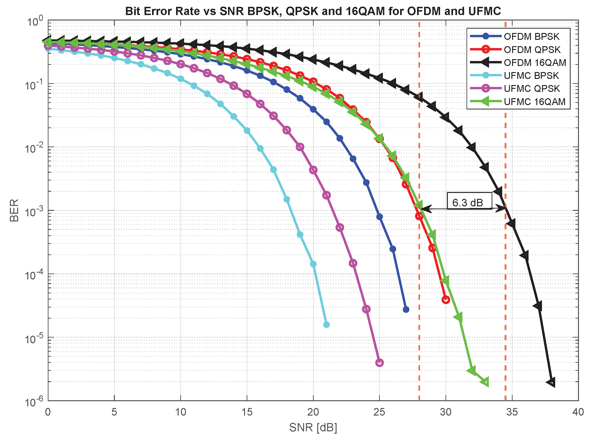
The parameters for UFMC were subsequently adapted to have a similar comparison base. This involved setting the number of effective subcarriers to N 256, employing 21 sub-bands, each containing 12 subcarriers, and using a Chebyshev filter length (L) of 19, approximately twice the size of the guard interval (GI). To calculate the bit error rate (BER), 10,000 symbols were generated, leading to the results.
