1. Introduction
Fifth-Generation Communication (5G) has significantly improved spectral efficiency, energy efficiency, and performance by utilizing different advanced technologies [
1,
2,
3]. As an integral part of the smart connected society in 2030, Sixth-Generation Communication (6G) will provide an all-round performance superior to 5G and cater to emerging smart services and applications [
4]. However, compared to 5G networks, 6G imposes higher requirements on various performance metrics [
5,
6], which require higher spectral efficiency [
7], higher energy efficiency [
8], and faster data rates [
9]. To achieve these excellent performances, many emerging technologies have been proposed, including Reconfigurable Intelligent Surface (RIS). RIS has strong beam-pointing gains and can significantly reduce energy usage and hardware expenses. It has become a very competitive technical solution to the above challenges and has attracted widespread attention in industry and academia. [
10,
11,
12].
The Reconfigurable Intelligent Surface (RIS) is a programmable structure that can change the electromagnetic properties of its own surface in real-time, making the direction of signal propagation change, which is expected to build a new paradigm of 6G intelligent programmable wireless environment [
13]. MIMO, as a key physical layer technology currently used in 5G communications, inevitably generates communication blocking, and RIS can effectively solve the blocking problem in this communication process, which is not only energy-efficient but also highly cost-effective [
14]. Its basic principle is to arrange adjustable panels on the surface of an outdoor building to reflect passive signals sent from the base station in any desired direction, thus intrinsically manipulating the propagation environment and achieving the goal of improving energy and spectral efficiency [
15,
16]. For RIS, there have been more research results [
17,
18,
19,
20,
21]. For example, [
17] investigated the electromagnetic and physical properties of RIS, and the authors developed a signal propagation attenuation model for wireless communication in free space after the inclusion of RIS, which is applicable in various scenarios, revealing that the signal propagation attenuation is not only related to the area of RIS, the distance from the transmitting end and the receiving end to the RIS, but also the direction of radiation between the antenna and the RIS unit, as well as the effect of the RIS’s long-/short-range action. Ref. [
18] focuses on the uplink of RIS-enabled multiuser MISO communication systems, and based on this, a channel estimation framework based on parallel factorization is proposed. Ref. [
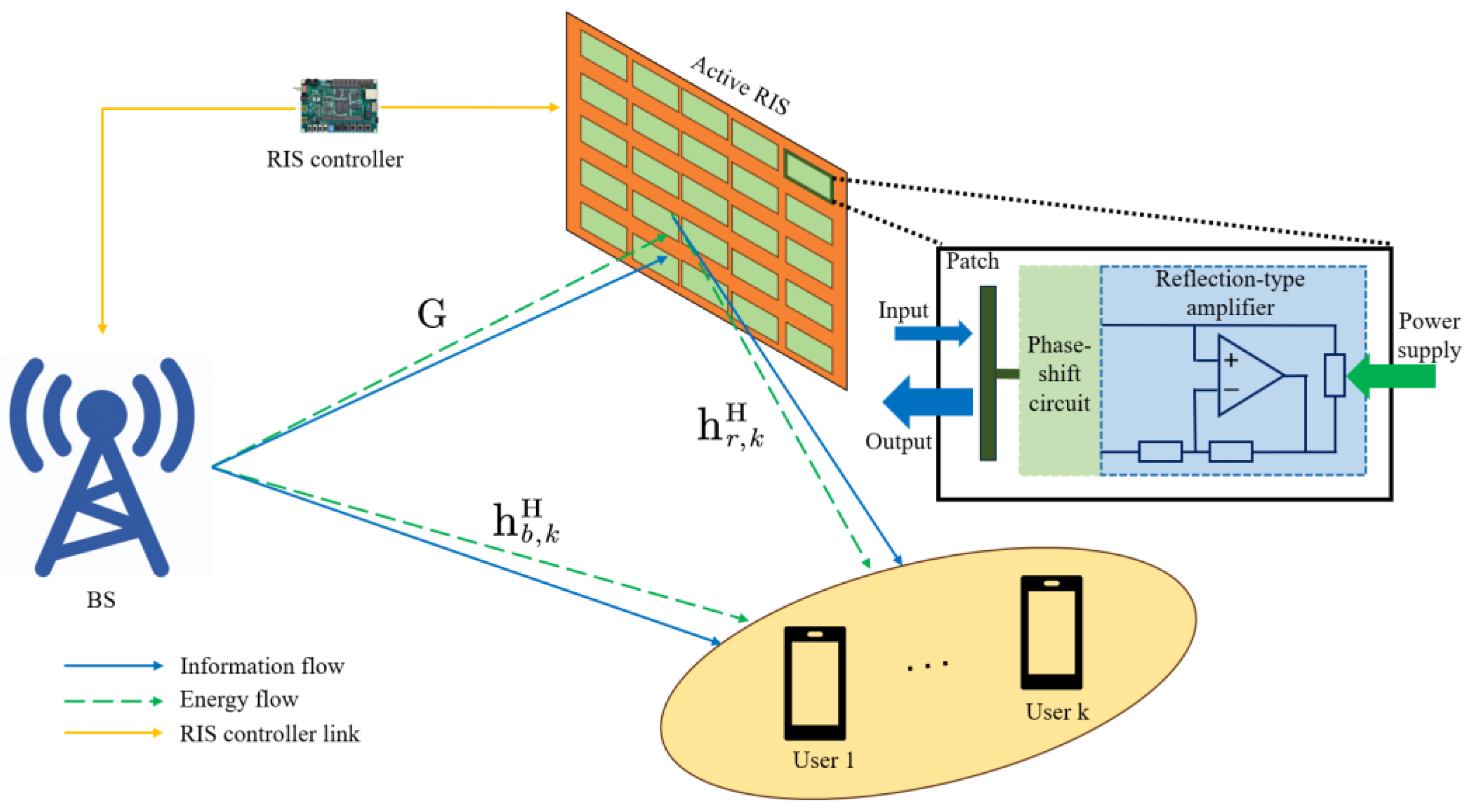
19] proposes a new concept of active RIS(A-RIS), which reduces the limitation of the “multipath fading” effect and solves the optimization problem of maximizing the summation rate in an A-RIS-assisted MU-MISO system. The physical implementation of the active RIS consists of two parts; first, the element has an internal phase-shift circuit which is responsible for changing the phase of the signal; in addition to this, each active RIS element is additionally equipped with an active reflection-type amplifier, which can amplify the reflected signals at the cost of affordable power consumption and hardware cost. Particularly, the reflection-type amplifier can be realized by many low-cost methods, such as current-inverting converter or asymmetric current mirror. Ref. [
20] also points out that, unlike passive RIS (P-RIS), A-RIS can both change the direction of the signal and increase its strength. The “multiplicative fading” effect due to the presence of BS to RIS channels and RIS to User K channels is overcome, and the size of the RIS is drastically reduced. Ref. [
21] added P-RIS and A-RIS to the same communication system, respectively, and after comparing them, it was discovered that the A-RIS system saves more power than the P-RIS system when the same performance is achieved.
The number of devices in 6G IoT communication has exploded, but the spectrum is becoming more and more scarce, and the energy is becoming more and more limited. To be able to effectively alleviate this problem, the Simultaneous Wireless Information and Power Transfer (SWIPT) technology came into being, which can effectively alleviate the spectrum and energy crisis [
22,
23]. Specifically, this technology can transmit signals to users while performing information decoding (ID) and energy harvesting (EH). Since signal receivers have different sensitivities, there are two typical receiver architectures in information and energy co-transmission systems, namely, the time splitting (TS) architecture, which uses time as the dividing factor, and the power splitting (PS) architecture [
24], which uses power as the splitting factor. With the PS architecture, any user can use a power divider to split the power of the received signal into two parts in a specified ratio, one for ID and the other for EH [
25]. Ref. [
26] investigates multiuser MISO networks with simultaneous information and energy users under incomplete channel state information by optimizing the information beam and energy so that the weighted sum of the total harvested power is maximized. Further, [
27] studied the power minimization problem under power splitting architecture and proposed two algorithms, optimal and suboptimal, with the suboptimal algorithm having lower complexity, and the results showed that the power splitting architecture can save the power loss of the system in a better way compared to the time splitting architecture. However, in the information and energy co-transmission communication system, the path loss determines the level of energy harvesting at the user end. To reduce the path loss, the energy-harvesting efficiency can be significantly improved by combining the RIS technology and multi-antenna technology using the dual beam-forming gain of the base station (BS) and RIS.
1.1. Related Work
There have been many research results on the combination of RIS technology and information and energy co-transmission technology [
28,
29,
30,
31,
32]. For example, [
28] investigated the base station radiant power minimization problem in SWIPT-based RIS-assisted MIMO communication networks in the hope of improving the energy utilization of the communication system to meet the needs of 6G green communication. Further, [
29] investigates a multi-user RIS-assisted MISO communication network based on SWIPT and achieves base station (BS) transmits power minimization based on a nonlinear energy-harvesting model, generalizing the results in [
27]. Ref. [
30] proposed a novel RIS-enhanced SWIPT system based on an EMC framework, which improves energy efficiency by optimizing the impedance parameters of the RIS elements with the active-shaped beam at the base station. Ref. [
31] investigated the problem of co-optimization of information rate and energy harvesting in a SWIPT-based RIS-assisted MISO communication network. To solve the problem, the optimal solution was obtained by using pricing-based, sequential, and alternating optimization methods. Ref. [
32] combines RIS-assisted SWIPT technology with Unmanned Aerial Vehicle (UAV) technology and develops iterative algorithms using methods based on successive convex approximations and alternating optimization to maximize the minimum average achievable rate for multiple devices. However, due to the defect of P-RIS “multiplicative fading”, the actual capacity gain that can be brought by the existing P-RIS is insignificant for typical communication scenarios with strong direct paths, which leads to a significant reduction in the energy harvested at the user end and the lack of existing research on the SWIPT-based multiuser RIS-assisted scheme for maximizing energy harvesting at the user end under MISO communication networks.
1.2. Motivation and Contribution
To solve the problem of low energy harvesting at the user end caused by path loss and “multiplicative fading” of P-RIS defects, this paper proposes a scheme to maximize the sum of energy harvesting at the user end under multi-antenna and multi-user scenarios for RIS-assisted multi-user MISO-SWIPT system. This ensures that the sum of the energy harvested by the user is maximized.
The main contributions of this paper are summarised as follows:
A communication scenario for transmitting information from multiple antennae to multiple users is considered, and a problem of jointly optimizing the BS beam direction vector, RIS phase shift matrix, signal amplitude enhancement coefficients, and power splitting factors to maximize the sum of energy harvesting at the user end is constructed under the constraints of maximum transmit power at the base station, power distribution ratio, and minimum signal to noise ratio at the user end. The problem is strongly coupled due to the entanglement of variables and requires further transformations.
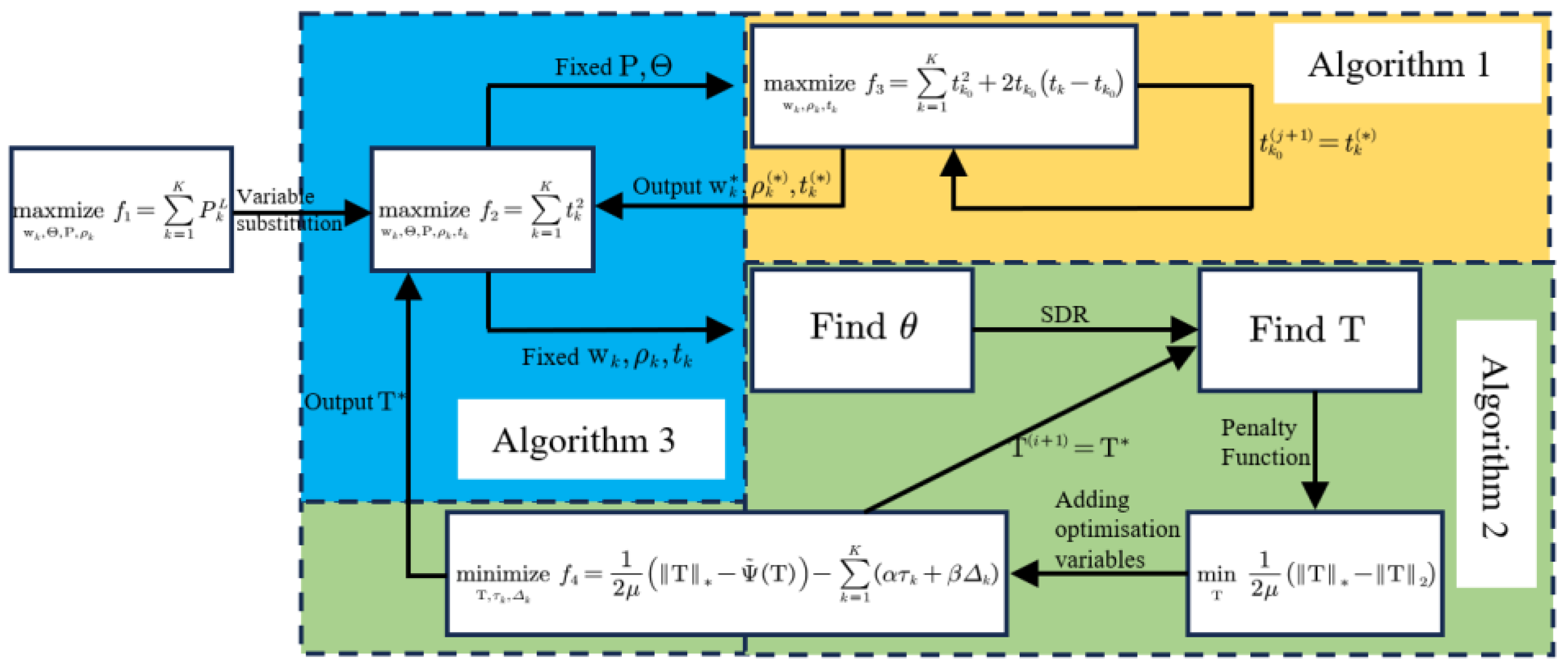
To transform this non-convex problem into a standard convex problem, this paper uses the overall BCD algorithm to split the optimization problem into two optimization subproblems. First, we fix and to solve . The optimization sub-objective is power reduced using Taylor series expansion, and then the non-convex problem is converted into a standard convex problem using semi-definite relaxation (SDR) and successive convex approximation (SCA). The optimal solution to the subproblem is obtained by continuous iterative optimization. Next, we fix to solve and . After transforming the objective function into a convex problem via slack variables, the convex problem can be solved via semi-definite programming. The penalty-based technique is then used to ensure that the obtained solution satisfies the rank one constraint. However, the convex difference function obtained is not a standard convex problem. We use successive convex approximations and Taylor series expansions to make it a standard convex problem. Then, iterative optimization is performed to obtain the optimal solution. Finally, the optimal solution of the initial optimization problem can be obtained by alternating the optimal solutions of the two optimization subproblems with iterative optimization.
Three benchmark scenarios were considered based on the optimization problem, and the simulation results demonstrate that the total sum of energy harvested at the user end is maximized with the assistance of A-RIS. Compared with the three benchmark scenarios, the total energy harvested by the user is significantly improved, and the algorithms remain converged after several iterations. In addition, this paper also demonstrates that the dynamic power splitting algorithm can better improve the sum of energy harvested by the user compared to the average power splitting algorithm.
1.3. Notation Note
All bold uppercase letters appearing in this manuscript represent matrices, and bold lowercase letters represent vectors. For a square matrix
,
,
,
,
and
denote its conjugate transpose, transpose, trace, trace paradigm, and rank, respectively. In addition,
denotes that the square matrix is a semipositive definite matrix. The diagonalization operation of the matrix is denoted by
.
,
,
, and
denotes the Euclidean paradigm, the absolute value, the gradient vector, and the expectation of
. A circularly symmetric complex Gaussian (CSCG) random vector is denoted as
, where
represents the covariance matrix and
represents the mean value.
indicates
dimensional complex matrices.
stands for the capital
symbol. The full names of all the abbreviations appearing in this paper are shown in
Table 1.
1.4. Organization
The remaining paper is presented as follows. In
Section 2, the system model of Multi-user MISO A-RIS-assisted SWIPT system is first established and the optimization problem is formulated.
Section 3 presents the overall algorithm and the computational complexity analysis. Simulations are executed in
Section 4.
Section 5 arrives at the conclusions of this paper.
2. System Models and Problem Modeling
In this paper, we study a multi-user, multi-input, single-output PS-SWIPT network model in which RIS is introduced as an aid, as can be seen in
Figure 1, which consists of a BS, RIS, and
single-input channels of users, where the BS has M input channels and the RIS has N reflector units. The set of users is defined as
. The set of array cells for RIS is
. Let
denote the flat fading channel gain of the BS-RIS,
denote the flat fading channel gain of the BS-the user
, and
denote the flat fading channel gain of the RIS-user
. All channels experience quasi-static flat gradient fading that remains constant over several symbols [
33]. Then the signal transmitted from the BS can be described as
where
represents the beam-former and
denotes the information symbol of user
satisfying
. In this way, the reflected signal of a P-RIS with N reflective elements can be written as
where
denotes the reflection coefficient matrix of the RIS, and
denotes the signal transmitted from the base station (BS).
If assisted by an RIS containing N reflective elements, the communication link can be strengthened, resulting in an increase in the energy power available to the user. If the base station (BS) transmits a signal strong enough to propagate through free space directly to a single user
without being blocked or reflected
en route, the role of P-RIS becomes negligible due to the “multipath fading” effect. To maximize the sum of the energy collected by all users in the communication area in any case, this paper adopts A-RIS to solve this problem. The biggest difference between A-RIS and P-RIS is that A-RIS can amplify the reflected signals, and compared with the traditional relay, A-RIS is smaller in size and more flexible in layout. The output signal of the incident signal after reflection that occurs through the A-RIS can be written as
where
represents the A-RIS amplification factor matrix with all elements greater than 1,
represents the dynamic noise at the A-RIS, and
represents the static noise at the A-RIS. In addition,
is only related to the device noise and input noise inherent in the A-RIS, whereas the static noise
is not related to
and can therefore be disregarded.
In the base station (BS) to the A-RIS channel, the signal received at the A-RIS can be represented as
In an A-RIS to single user
channel, the signal received by the user
can be described as
where
represents the total channel gain from the base station to user
, and
represents the complex Gaussian noise received at user
. At this point, the base station (BS) uses the available time and frequency resources to transmit signals to all single users, and the energy power received by the user is divided into two parts ID and EH. We set
as the PS ratio, where part
is used for ID, so the decoded signal from user
can be described as
where
is the additional noise generated by the signal processing circuitry of the single user
when performing information decoding. Part
is used for EH, so the energy-harvesting signal of user
can be expressed as
Based on this, the signal-to-noise ratio at a single user
can be expressed as
For the energy-harvesting (EH) circuit, this paper adopts the linear model from the literature [
34], whose linear input power is denoted by
. The energy harvested at user
can then be described as
where
represents the energy conversion efficiency of user
. In this paper, we assume that the energy conversion efficiency of all users is 100%, i.e.,
.
After modeling the signal and energy, the sum of energy harvesting at the user end is maximized by co-optimizing the base station beam-former, the PS ratio, and the RIS phase shift/amplification factor, a problem that can be described as
where (10) is the sum of energy collected by the user, and the optimization objective in this paper is to maximize it. Equation (11) is the signal-to-dry noise ratio constraint for user
, and
is the minimum signal-to-dry noise ratio threshold required for user
. Equation (12) denotes the reflected power constraint of the A-RIS, and
is the maximum reflected power threshold of the A-RIS. Equation (13) denotes the radiant power constraint of the BS, and
is the maximum radiant power threshold of the BS. Equation (14) represents the PS factor scaling constraint. Since the variables are entangled with each other and strongly coupled, the problem (P1) is non-convex and cannot be solved directly using the software CVX, so the next step is to turn the problem (P1) into a convex problem.
3. Proposed Algorithm
To transform the problem (P1) from a non-convex to a convex problem, the variable
is introduced below, so (P1) can be rewritten in the following form:
The problem (P2) is not a convex problem because the variables are entangled with each other and there is a strong coupling relationship, so it cannot be solved by CVX, the most popular method for solving convex problems. To solve this problem, the optimization objective is first Taylor’s first-order expansion, due to the strong coupling relationship between the variables, and then we use the overall BCD algorithm. After first fixing the RIS phase matrix and the signal strength increase coefficient , Semidefinite Relaxation (SDR) and Successive Convex Approximation (SCA) are used to optimize the base station (BS) beam-former , the PS ratio and , iterating until convergence. The converged base station (BS) beam-former , and PS ratio and are used as known quantities to design the RIS phase matrix and signal strength increase coefficient . The outputs of the last two components are optimized iteratively with each other until convergence.
3.1. Optimizing Given and
Since and appear as products in problem (P2), we define such that optimizing and is equivalent to optimizing the RIS precoding matrix of . Next, the optimization objective (15) is transformed into a first-order function using the following lemma.
Lemma 1 (Taylor series expansion formula). Assuming that the function has a derivative of order on some closed interval containing and a derivative of order on the open interval , the following equation holds for any point on the closed interval [35]:where represents the remainder term of the Taylor series expansion formula, which can be ignored in the conversion since it is an infinitesimal term. A Taylor first-order expansion of using Lemma 1 above gives In addition to this, this paper defines
and
so that (15) can be transformed into the following form:
For (16), we define
. The following process can be obtained by shifting terms:
For (17) and (18), there is the following process due to
:
For (19), due to
, the following process is assumed to be
for all users:
For (20), due to the use of SDR and SCA optimization methods, the rank-one constraints are to be relaxed on the original constraints, which can be expressed as
To make (P3) a convex problem, we relax the rank-one constraints. The optimization objective of (P2) is to find the maximum value of
, which can be equated to finding the maximum value at the minimum point
in the function
. After expanding it with Taylor’s first-order series, it is a first-order linear function, which can be solved efficiently by CVX as the same constraints as in (P3), and the solution obtained by substituting
as a new
repeats the process of solving and iterating until convergence, which leads to the final
. These solutions have a unique rank and can be proved by solving the KKT condition using the Lagrangian dyadic method [
36].
3.2. Optimizing Given
After solving the problem (P3), the next step is to find suitable and so that they satisfy the constraints of (P2), and we define . To make the problem easier to deal with, we use the variables and , where , , and . This way, the optimization problem (P4) can be obtained via the following steps.
For (P2), due to
, (16) can be rewritten by the following process:
For (17), it can be rewritten by the following process:
For (27), since
, it can be rewritten by the following process:
Thus, (P3) is transformed into (P4) as follows:
(P4) is not a convex problem because it contains quadratic inequality constraints, and to turn it into a solvable convex problem, the SDR technique is used. Introducing variables
and
,
can be defined, which requires
and
to satisfy the rank one constraint. After relaxing the rank one constraints, (P5) can be obtained by rewriting it in this way:
In this way, the optimization problem (P4) is transformed into finding a suitable T as follows:
where
and
in (35) and (36) have zero rows and zero columns more than the other matrices. After the transformation of (P5) into an SDP problem, we can use CVX software (version 3.0) to solve this convex problem. Due to the SDR technique, the resulting solution does not satisfy the rank-one constraint. To obtain a solution with only a unique rank, a penalty-based approach can be used. The rank one constraint can be described in the following equivalent form:
For any given
, the following equation holds if and only if the rank of
is 1:
where
is the
th singular value of
. After adding the rank-one constraint, (P5) can be rewritten in the following form:
where
is the penalty factor, and only when the value of
reaches a very small value does (P6) obtain a solution with only a unique rank. It is worth noting that (P6) is non-convex because its optimization objective function is the subtraction of two convex functions, which does not guarantee that the resulting difference is necessarily convex. This problem can be solved by using the SCA technique. Using Taylor series expansion to represent
, its first-order expansion can be used in place of
, and this is the global minimum since
is a convex function and its first-order expansion is as follows:
where
. Inside
is the eigenvector, which corresponds to the largest eigenvalue of
. (P6) already has an optimization objective function inside and hence is a feasibility problem; any solution that satisfies the constraints and has a unique rank is optimal. Therefore, we can add additional optimization variables to this so that the optimal solution obtained can have better performance. Therefore, it is decided to optimize the SINR and harvest energy boundaries while satisfying the constraint of having a unique rank. To obtain the optimal solution, two new relaxation variables
and
are introduced as “SINR residuals” and “energy harvesting residuals”, respectively, and with the introduction of the additional new variables (P6) can be rewritten as follows:
The flowchart of the overall algorithm proposed in this paper is shown in
Figure 2.
Figure 2.
Flowchart of the overall algorithm (As shown in Algorithms 1–3).
Figure 2.
Flowchart of the overall algorithm (As shown in Algorithms 1–3).
| Algorithm 1 Set the maximum number of iterations , = 0, fix , initialize . |
(1) while do
(2) Solve P(3), output , update
(3) Let
(4) end while
(5) Output |
| Algorithm 2 Set the maximum number of iterations , = 0, fix , initialize . |
(1) while do
(2) Calculation of according to (8)
(3) Solve P(7), output , update
(4) Let
(5) end while
(6) Output |
| Algorithm 3 Set the maximum number of iterations , = 0, and initialize . |
(1) while do
(2) Given solves P(3) and outputs
(3) Given solves P(7), output according to Algorithm 2 and update
(4) Let
(5) end while
(6) Output |
Remark 1 (Complexity Analysis). The overall complexity of the proposed BCD algorithm (Algorithm 3) arises from two components: Algorithm 1 for solving subproblem 1 and Algorithm 2 for solving subproblem 2. In each iteration of the BCD algorithm (Algorithm 3), we independently address problems (23) and (45). To illustrate the complexity related to Algorithm 1, which addresses the convex problem (23), its algorithmic complexity can be expressed aswhere represents the given solution accuracy, denotes the number of iterations before convergence, is the total number of users, and is the number of antennae. The algorithmic complexity for solving the SDP problem (45) with Algorithm 2 can be expressed aswhere represents the given solution accuracy, denotes the number of iterations before convergence, is the total number of users, and is the dimension of the semidefinite cone. In summary, the overall complexity of the BCD algorithm (Algorithm 3) is given bywhere represents the total number of iterations executed by Algorithm 3.
4. Simulation Results and Discussion
To validate the reliability of the proposed energy-harvesting sum maximization algorithm at the user end, this paper compares the proposed energy-harvesting sum maximization algorithm at the user end with three benchmark scenario algorithms, respectively, which are designed as follows: (1) A-RIS-assisted using average power splitting algorithm (); (2) P-RIS-assisted algorithm; and (3) traditional RIS-assisted algorithm without RIS. The propagation loss model is used in this paper, where denotes the propagation loss at , denotes the link distance, and represents the propagation loss index. The propagation loss indices from the base station to the RIS and the user are assumed to be and , respectively, and the propagation loss index from the RIS to the user is assumed to be . It is assumed that all channels undergo flat-terrain attenuation and maintain stability over time. The other parameters of the proposed energy-harvesting sum maximization algorithm at users are set as follows: the number of reflective units of the RIS ; the number of base station input channels ; the number of users ; the maximum number of iterations ; the minimum signal-to-dryness-noise ratio required for each user ; the maximum radiant power of the A-RIS ; the maximum radiant power of the base station antennae ; the noise power , , ; and the penalty factor .
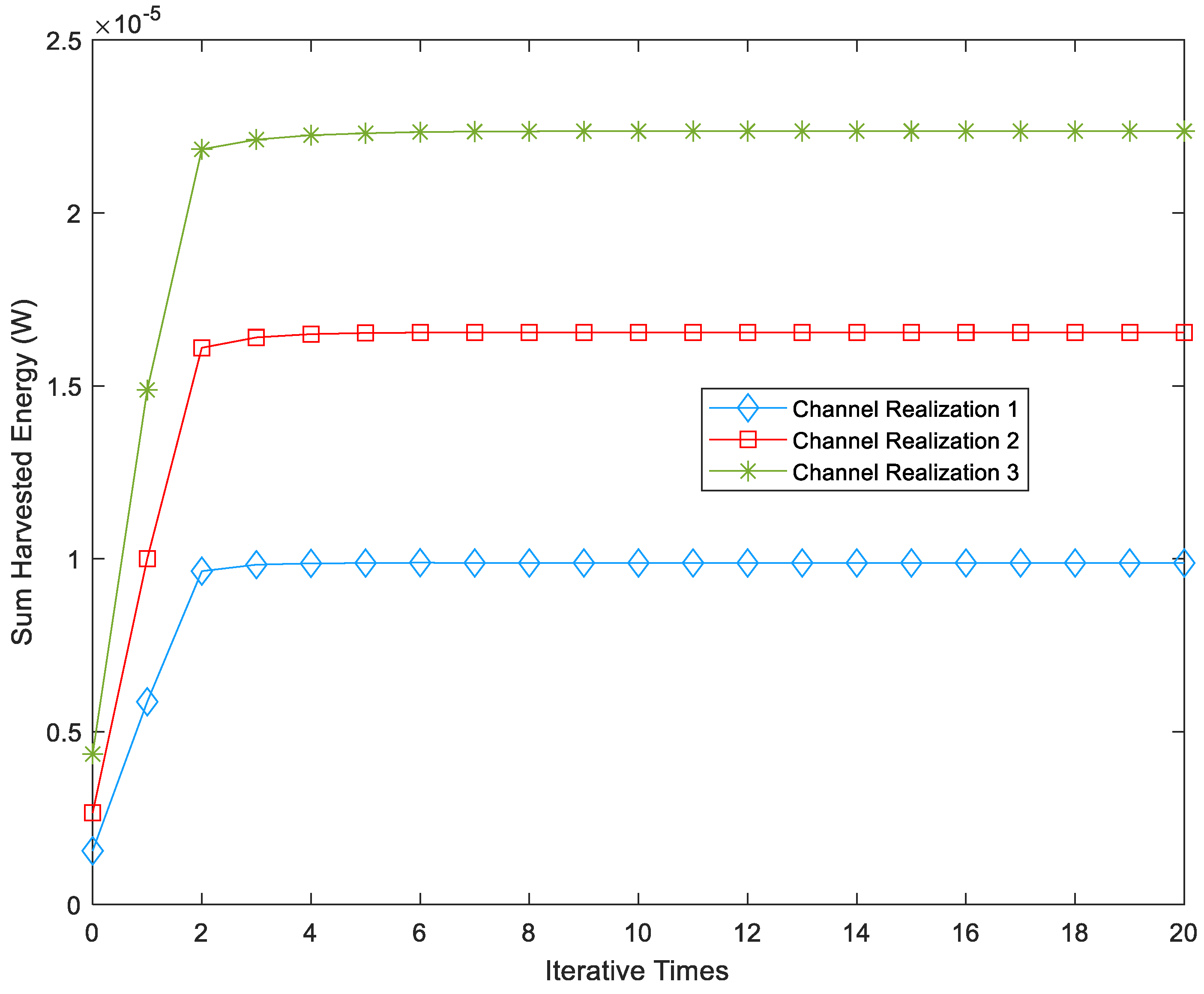
Figure 3 illustrates the convergence curves of the proposed algorithm for maximizing the sum of energy harvesting at the user’s location under different channel conditions. Channel 1 represents the BS-user K channel, channel 2 represents the BS-Passive RIS-user K channel, and channel 3 represents the BS-A-RIS-user K channel. From
Figure 3, it can be observed that the proposed algorithm for maximizing the sum of energy harvesting at the user’s location can reach a stable value relatively quickly after 2–3 iterations, demonstrating good convergence. The stable value of the proposed algorithm under Channel 1 conditions is 35.1% higher than that under Channel 2 conditions. This improvement is attributed to the A-RIS’s ability to provide additional transmit power to enhance signal strength, overcoming the drawback of substantial signal degradation due to the passive RIS’s inherent “multiplicative fading”. As a result, the user receives more energy, leading to a larger sum of harvested energy at the user’s location. Furthermore, the stable value of the proposed algorithm under Channel 2 conditions is 67.5% higher than that under Channel 3 conditions. This is because the P-RIS can adjust its reflection array phase to change the transmission beam direction of the base station antenna, thereby enhancing the transmission efficiency of the beam. As a result, the user receives more energy, and the proposed algorithm for maximizing the sum of energy harvesting at the user’s location harvests more energy.
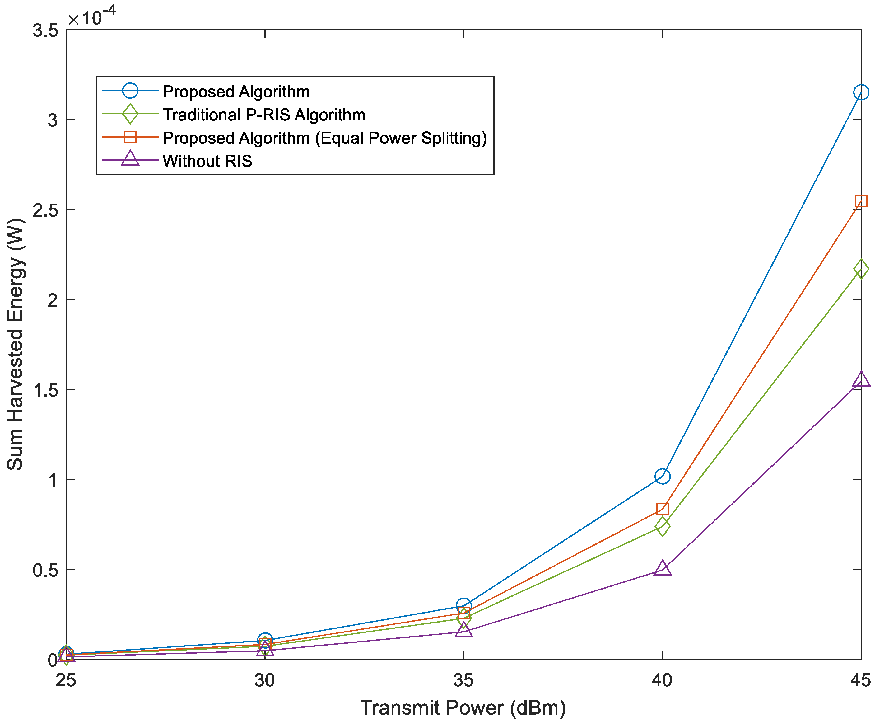
Figure 4 illustrates the variation in total energy collected at the user’s location under different transmission scenarios as the maximum allowable transmit power of the base station changes. This encompasses considerations for the number of reflecting elements in the RIS and the number of antennae at the base station. The graph reveals that with an increase in the base station’s maximum allowable transmit power, there is a corresponding rise in the total energy collected at the user’s location for all algorithms. In comparison to the P-RIS-assisted algorithm, the A-RIS-assisted algorithm, employing dynamic power splitting, demonstrates gains of 36.5% and 45.2% when the base station’s maximum allowable transmit power is set at 40 dBm and 45 dBm, respectively. This improvement is attributed to the A-RIS’s ability to not only manipulate the phase of the reflected signal but also amplify its transmit power, overcoming the significant signal power decay resulting from dual-path loss. The P-RIS-assisted algorithm achieves gains of 48.7% and 40.3% when the base station’s maximum allowable transmit power is 40 dBm and 45 dBm, respectively. This is owing to the P-RIS’s capacity to achieve a high-array gain of the reflected beam by adjusting the phase of the reflected signal. Compared to traditional RIS-assisted algorithms without an RIS, the P-RIS-assisted algorithm provides gains of 48.7% and 40.3% when the base station’s maximum allowable transmit power is 40 dBm and 45 dBm, respectively. Furthermore, in terms of power splitting algorithms, both under A-RIS assistance, the dynamic power splitting algorithm outperforms the average power splitting algorithm (
), resulting in increases of 21.7% and 23.5% in the total energy collected at the user’s location when the base station’s maximum allowable transmit power is set at 40 dBm and 45 dBm, respectively. This is due to the dynamic power splitting algorithm offering greater optimization flexibility, allowing more power to be split to enhance the total energy collected at the user’s location, consequently leading to a higher energy harvest.
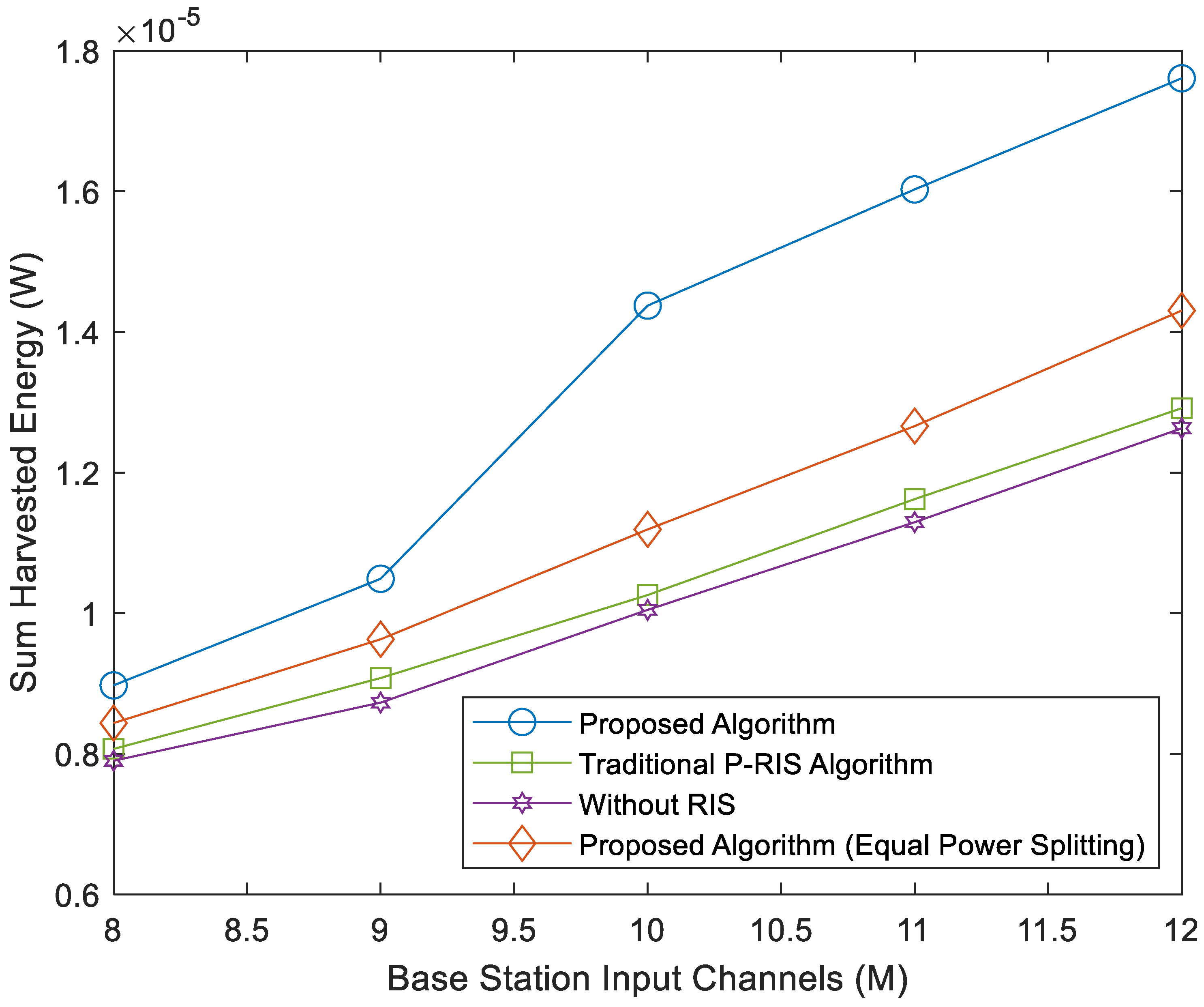
Figure 5 plots the comparison curves of the total energy collected by the user for several different algorithms with different numbers of base station transmitting antennae, where RIS has 12 reflective units, i.e., N = 12. As can be seen from
Figure 5, the total energy collected by the user under several algorithms increases accordingly after the increase in the base station input channel M. The main reason for this is that the transmitting beamwidth of the BS is fixed, and with the increase in the base station input channel, the transmitting beamwidth of each antenna becomes narrower, which increases the additional array gain, and the available degrees of freedom of the system increases, and the performance improves consequently, and the total amount of energy collected at the user end under the various algorithms increases as well. Also, since the A-RIS has a feature that the P-RIS does not have, i.e., the enhancement of the transmitted power of the reflected signals, it allows for an increase in the power of the received signals at the user end, which results in more power being used for energy harvesting (EH); thus, the A-RIS-assisted energy-harvesting algorithm improves the sum of the energy harvested at the user end as compared to the P-RIS-assisted energy-harvesting algorithms. In addition to this, the use of the dynamic power partitioning algorithm is very effective in improving the total energy collected by the user; this is because the dynamic power partitioning algorithm improves the degree of freedom of the optimization so that more power can be used to improve the total energy collected at the user end. Compared to the average power splitting algorithm (
), the dynamic power splitting algorithm is used to improve the total energy collected by the user by 23.1% at the number of input channels M = 12.
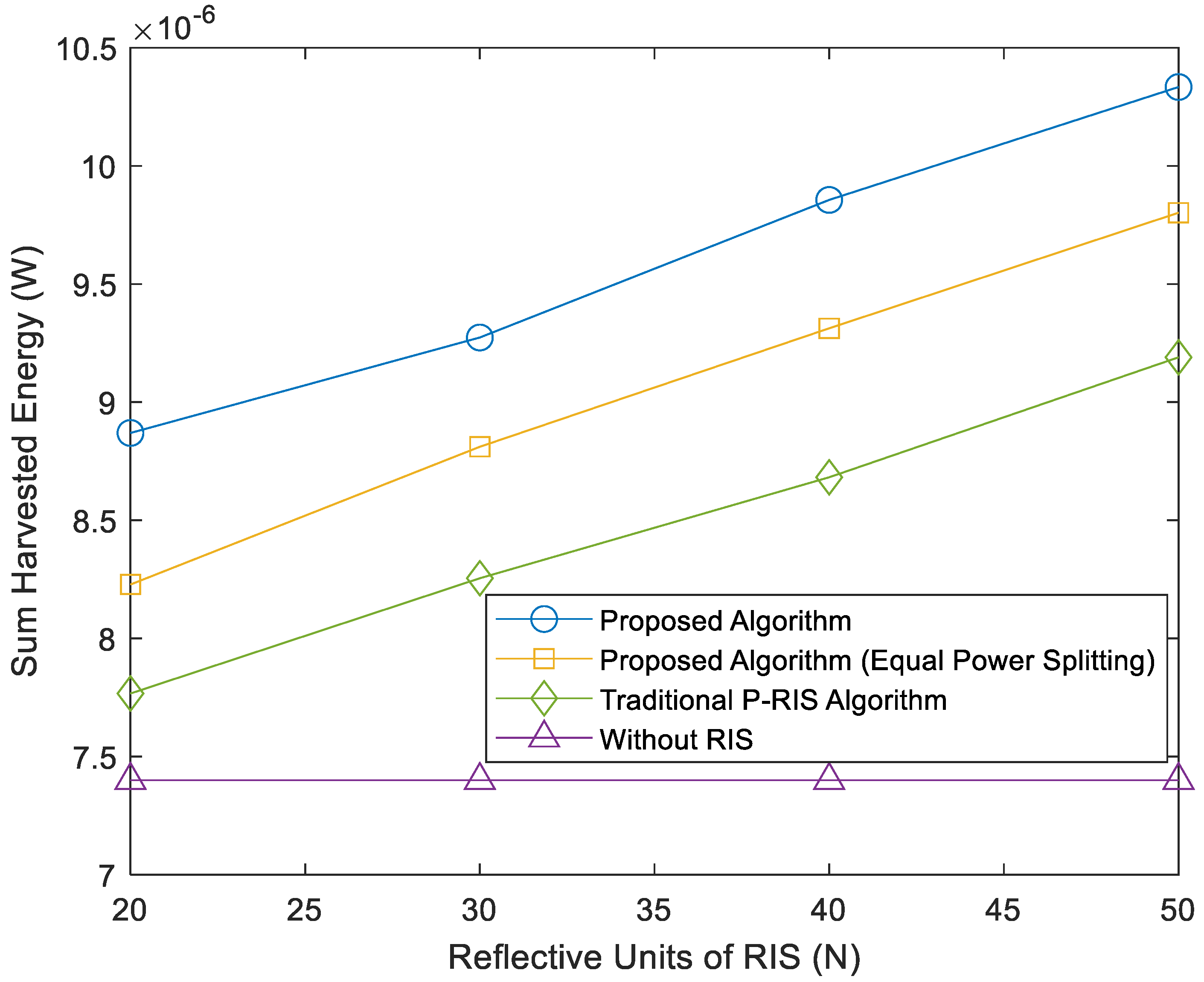
To evaluate the effect of different numbers of reflection units on the performance of each algorithm,
Figure 6 shows the effect of different numbers of reflection units on the total energy collected from the user under each algorithm, where the number of input channels at the base station is M = 20. It can be observed from
Figure 6 that there is no relationship between the total energy collected from the user and the reflection units for the traditional algorithm without RIS assistance, mainly because the RIS has been removed from the algorithm. This led to no change in the total energy captured by the user as the number of reflection units increased. With the increase in the number of reflection units, the energy collected by the user of the proposed three algorithms, namely, the energy-harvesting algorithm with dynamic power splitting assisted by A-RIS, the energy-harvesting algorithm with average power splitting (
) assisted by A-RIS, and the energy-harvesting algorithm assisted by P-RIS, increases and the performance of the algorithms is also enhanced. This finding also laterally verifies that configuring more reflection units can increase the reflection path from the base station to the user, further expanding the multipath propagation and making the received array gain at the user end larger, and by optimizing the RIS phase shift, the received signal power at the user end is enhanced so that more power is used to boost the total energy collected at the user end. In addition, as shown in
Figure 6, when using the energy-harvesting algorithm assisted by the A-RIS, the total energy collected by the user is further increased because the A-RIS amplifies the signal strength, and the total energy collected at the user end can be effectively increased compared to the use of the P-RIS.
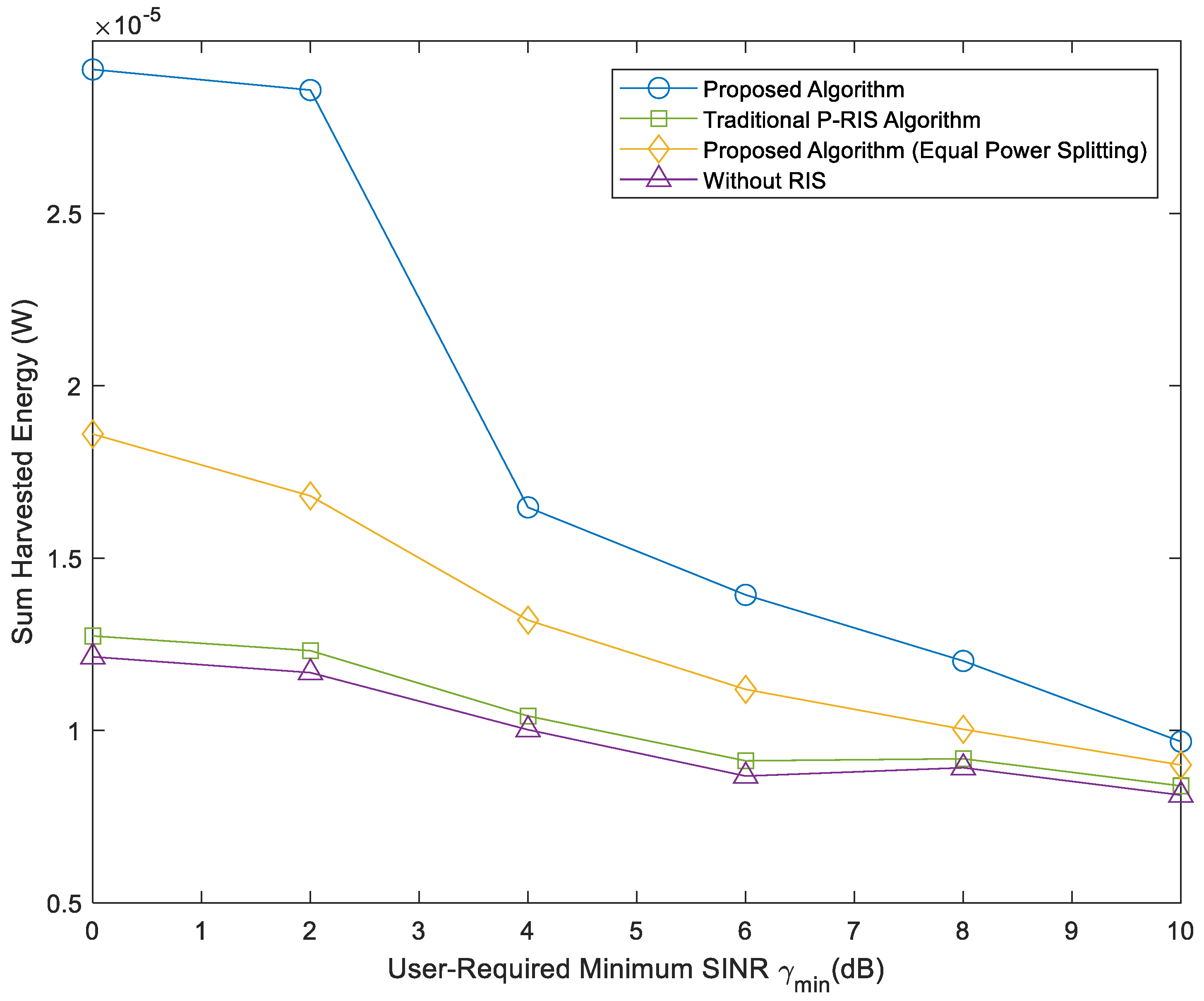
Figure 7 shows the variation curves of the energy collection performance of several different algorithms at the user end for different user-required minimum signal-to-dry-noise ratio
, where the number of reflector units of RIS is N = 12 and the number of base station input channels is M = 20. It can be seen from
Figure 7 that with the increase in the user-required sub-minimum signal-to-dry noise ratio
, the user’s energy collection of several algorithms decreases correspondingly, and the total energy collected decreases accordingly. The main reason for this phenomenon is that to satisfy the more stringent user minimum SINR
constraint, the base station antenna (BS) needs to allocate more power to the user for information decoding (ID), which results in less power left to be allocated for energy harvesting (EH), resulting in lower energy harvested from the user. It can also be seen that due to the presence of dual path losses, the sum of energy harvested by the user by the P-RIS-assisted energy-harvesting algorithm does not differ significantly compared to the conventional RIS-assisted energy-harvesting algorithm without RIS-assisted energy harvesting. However, since the dynamic power splitting energy-harvesting algorithm with A-RIS assistance proposed herein can give full play to the advantage that A-RIS can amplify the reflected signal radiant power, it can overcome the defect of the “multiplicative fading” of P-RIS so that the sum of energy harvested at the user end can be improved. Further, the dynamic power partitioning algorithm increases the degree of freedom of the optimization so that more power is available for energy harvesting (EH), resulting in more energy harvested by the user. The sum of energy harvested at the user end with the dynamic power splitting algorithm is improved by 70.1% compared to the energy-harvesting algorithm with average power splitting (
) assisted by A-RIS when the minimum required signal-to-dry noise ratio
= 2 dB at the user end is satisfied.
5. Conclusions
This paper investigates how to solve the problem of the shortage of energy harvested by users in communication systems based on the multi-user MISO system model using the A-RIS-assisted SWIPT technique, which can significantly improve the sum of energy harvested by users. In this paper, the problem of maximizing the sum of energy harvested by the user is established under the constraints of the minimum signal-to-dry noise ratio required by the user, the maximum power of active RIS, the maximum power of the base station, and the PS ratio. The algorithm for maximizing the sum of energy captured by the user is proposed through the joint optimization of the BS beam-former, power splitting factor, RIS phase matrix, and signal strength increase. For the proposed optimization problem, Algorithms 1–3 are used to transform the original problem into a convex problem which is first solved by local iterations, and finally, the whole is optimized alternatively. The numerical values show that the proposed algorithm has good convergence. At the maximum allowable radiant power of 40 dBm and 45 dBm at the base station, the total energy captured by the user using the A-RIS-assisted algorithm is improved by 48.7% and 40.3%, respectively, compared to the P-RIS-assisted algorithm. In addition, with A-RIS assistance, the use of the dynamic power splitting algorithm improves the system degrees of freedom by 21.7% and 23.5% of the total energy collected by the user compared to the use of the average power splitting algorithm (), respectively.


