

Technical, Qualitative and Energy Analysis of Wireless Control Modules for Distributed Smart Home Systems


Abstract
:1. Introduction
1.1. Related Work
1.2. Contributions
2. Materials and Methods
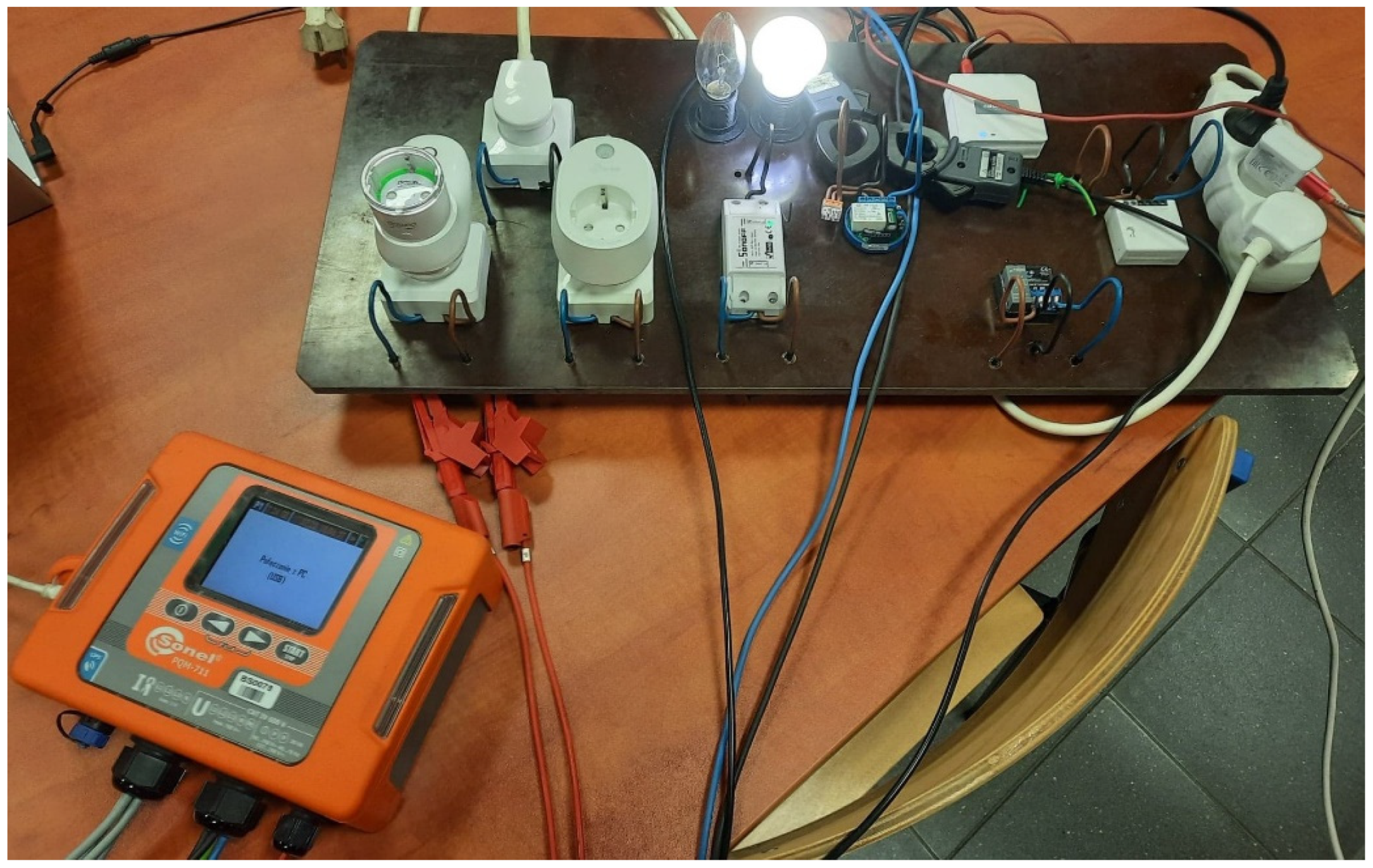
2.1. Mesurement Stand
2.2. Selected Smart Home Modules
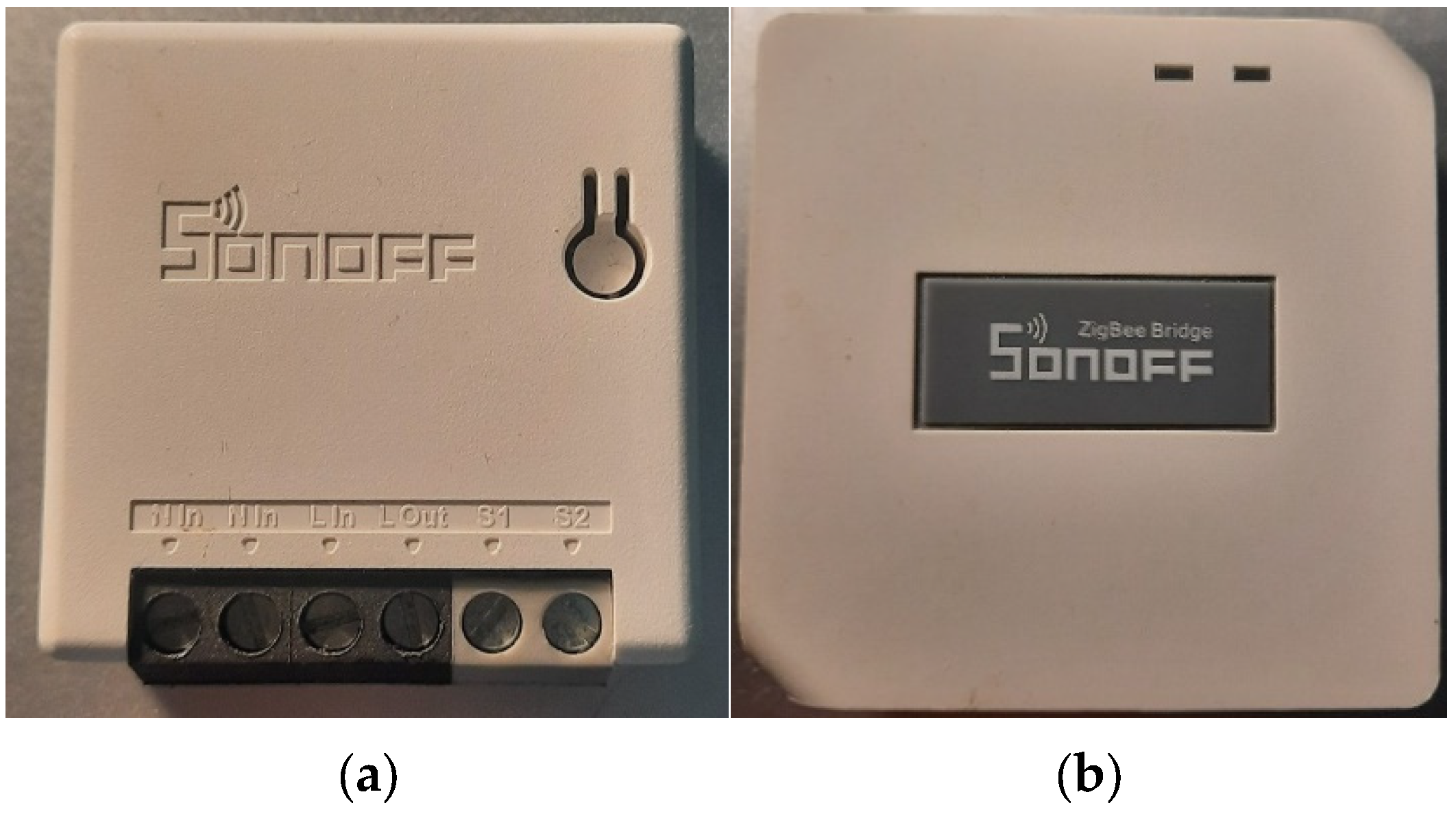
2.2.1. Sonoff ZBMINI Switch
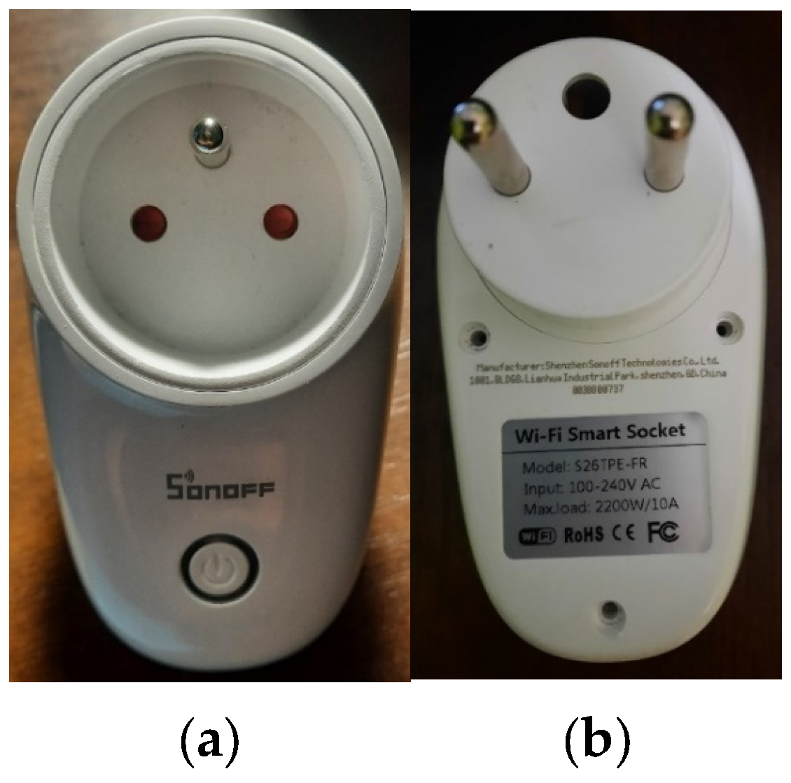
2.2.2. Sonoff Socket
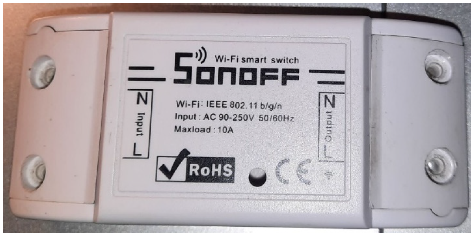
2.2.3. Sonoff Basic Switch
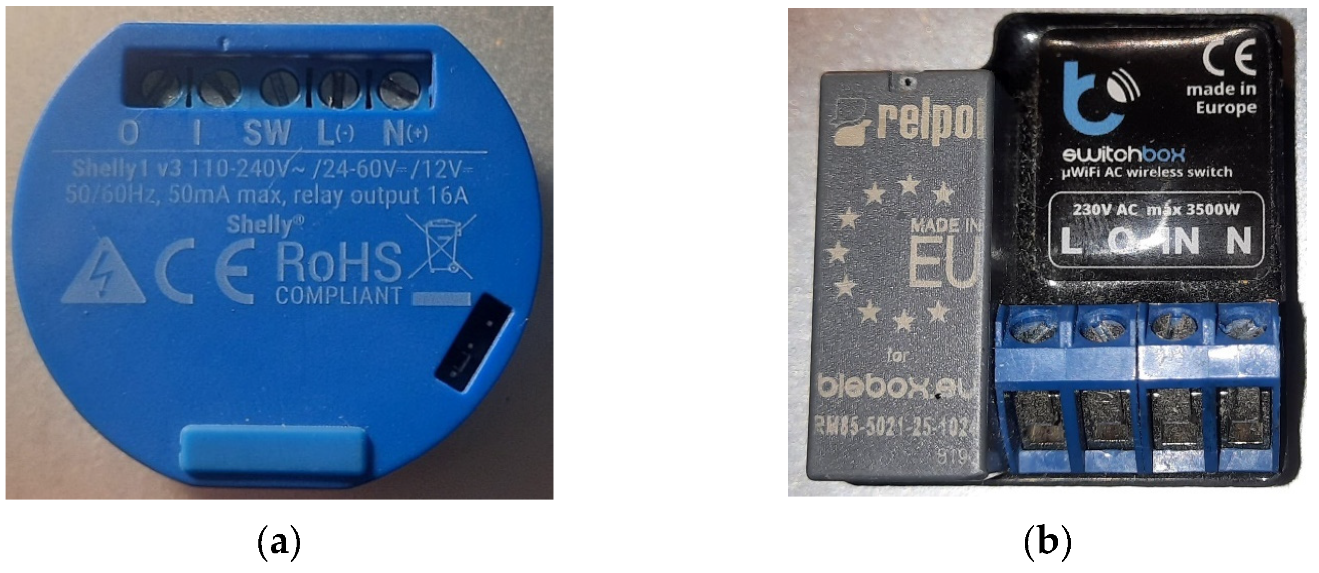
2.2.4. Shelly 1 Switch
2.2.5. Blebox Switchbox
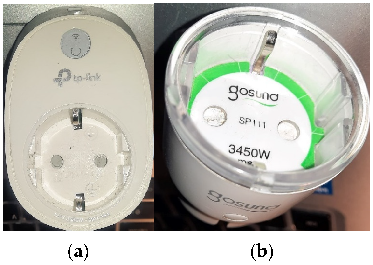
2.2.6. Tplink Socket
2.2.7. Gosund Socket
2.3. Measurement Unit and Measurment Data Aqusition
3. Results
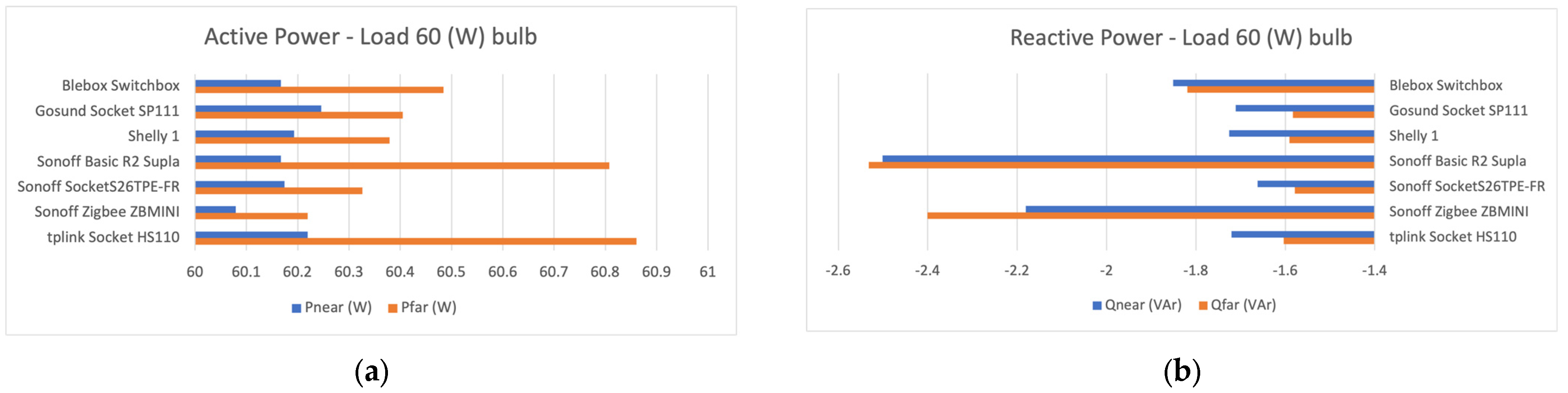
- Classic bulb, 60 Watt
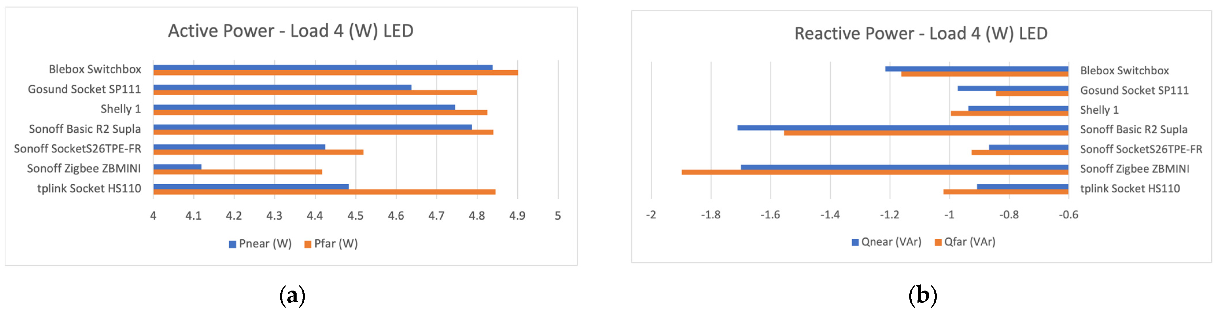
- LED lamp, 4 Watt
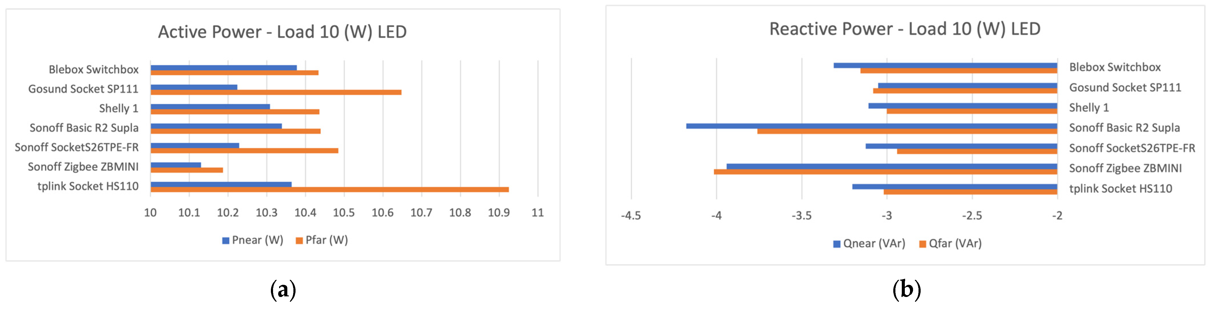
- LED lamp, 10 Watt
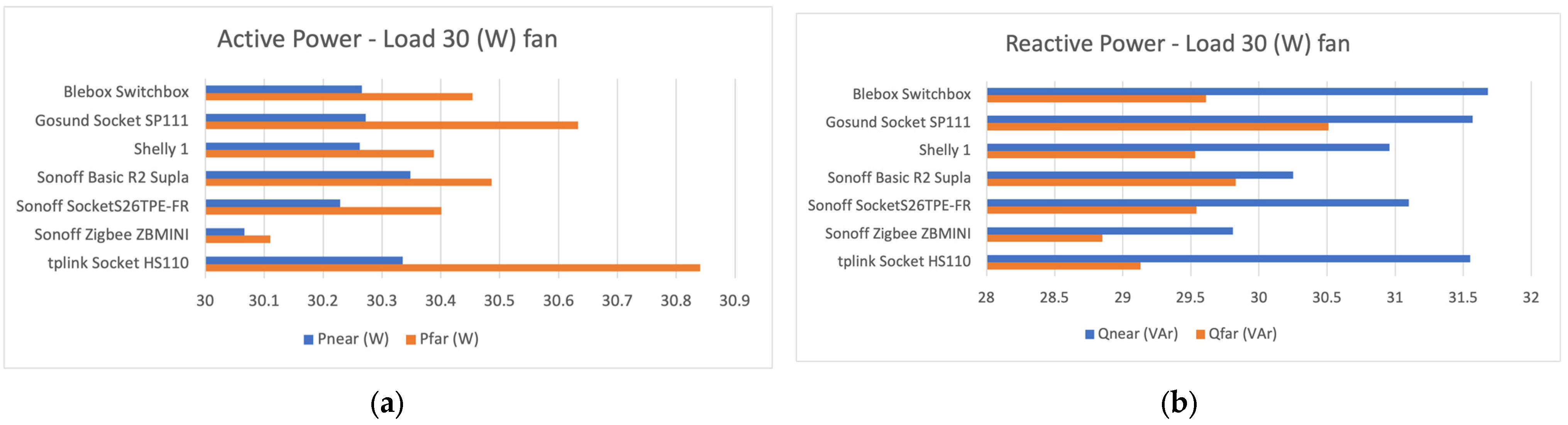
- Room fan, 30 Watt
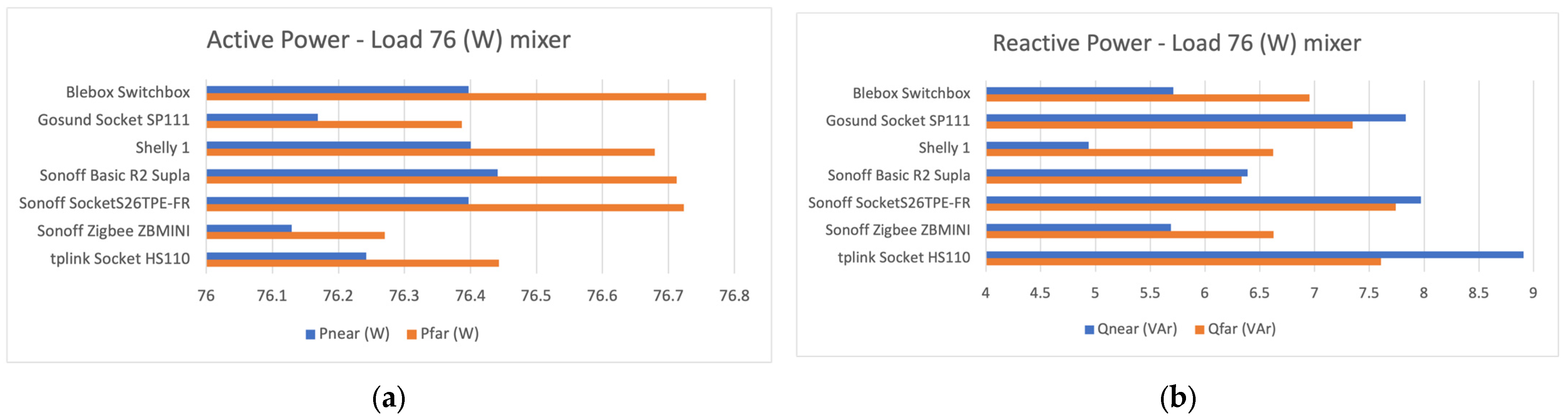
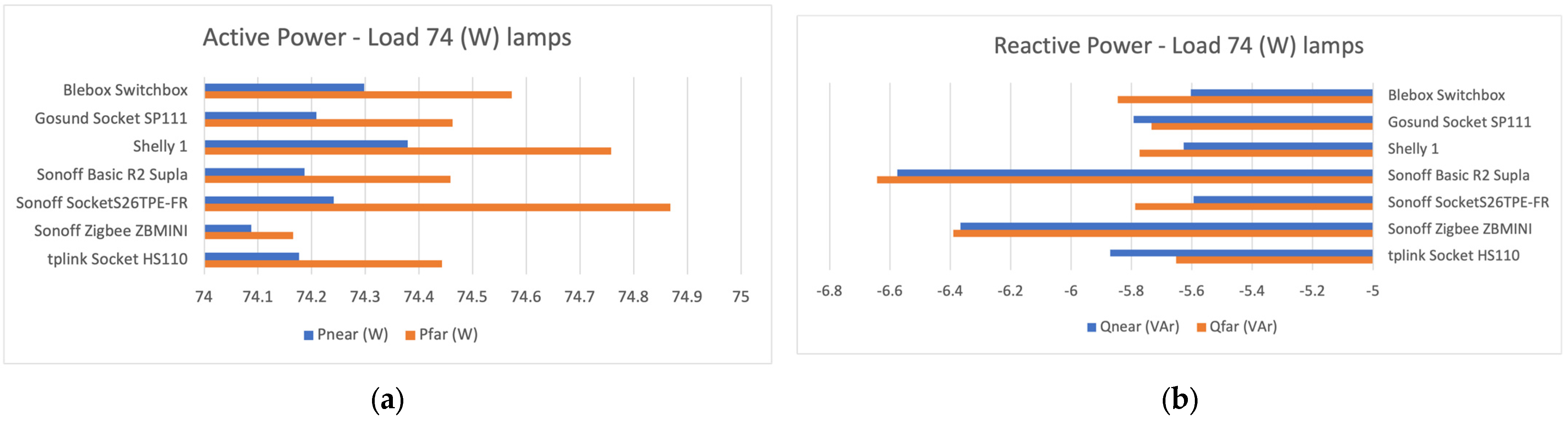
- Kitchen mixer, 76 Watt (high-speed mode)
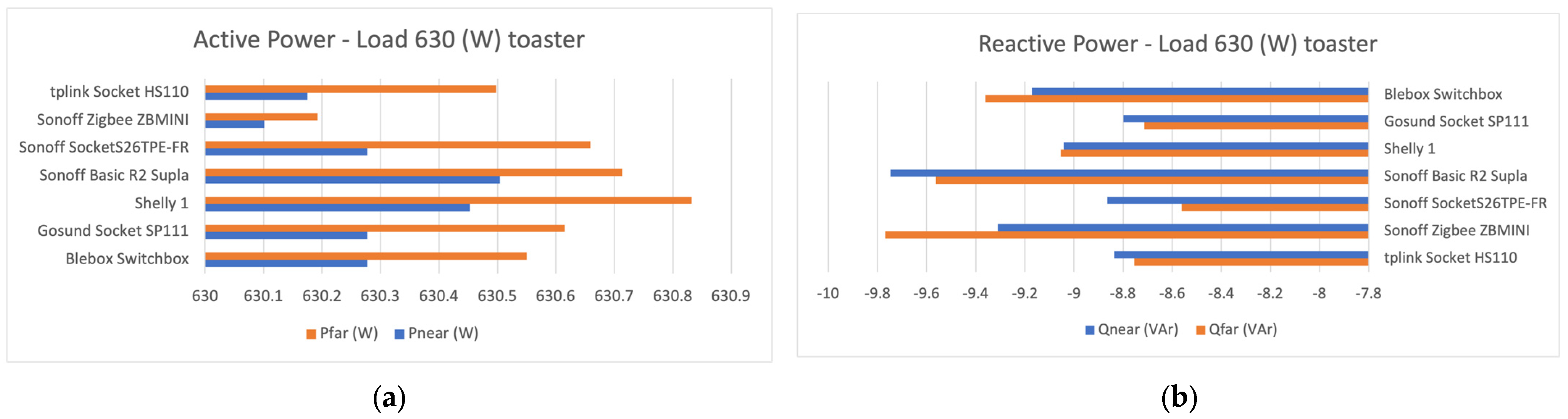
- Toaster, 630 Watt
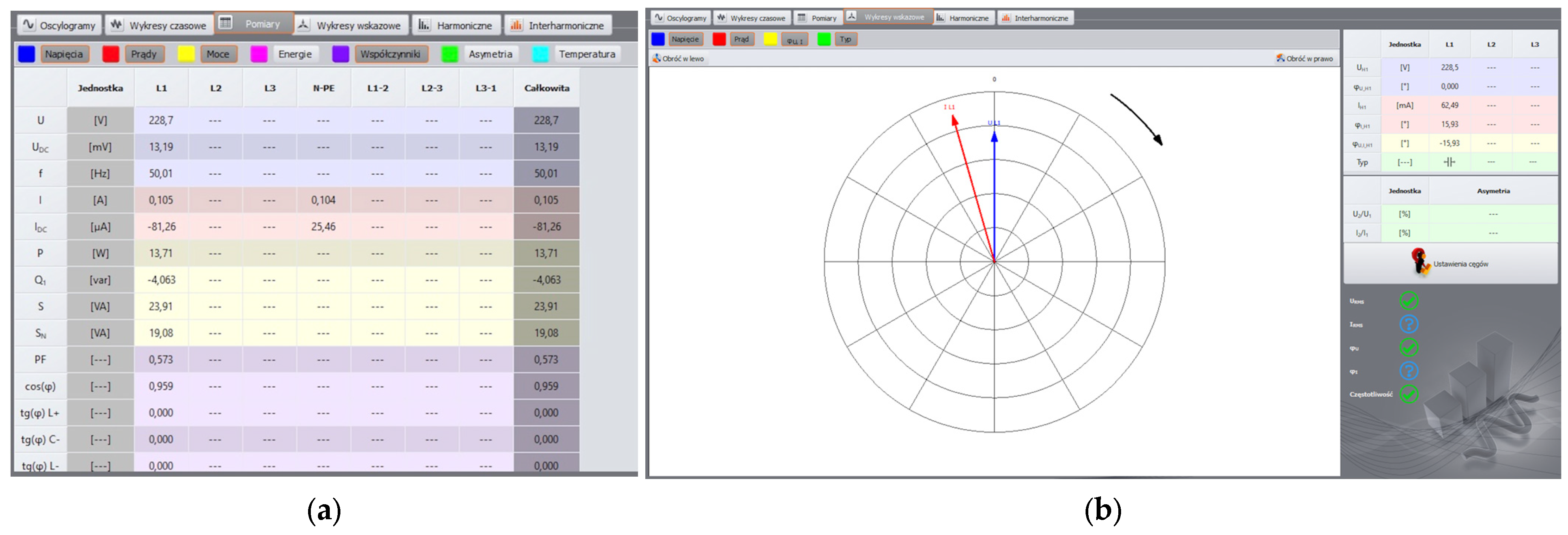
3.1. Active and Reactive Power Measurements
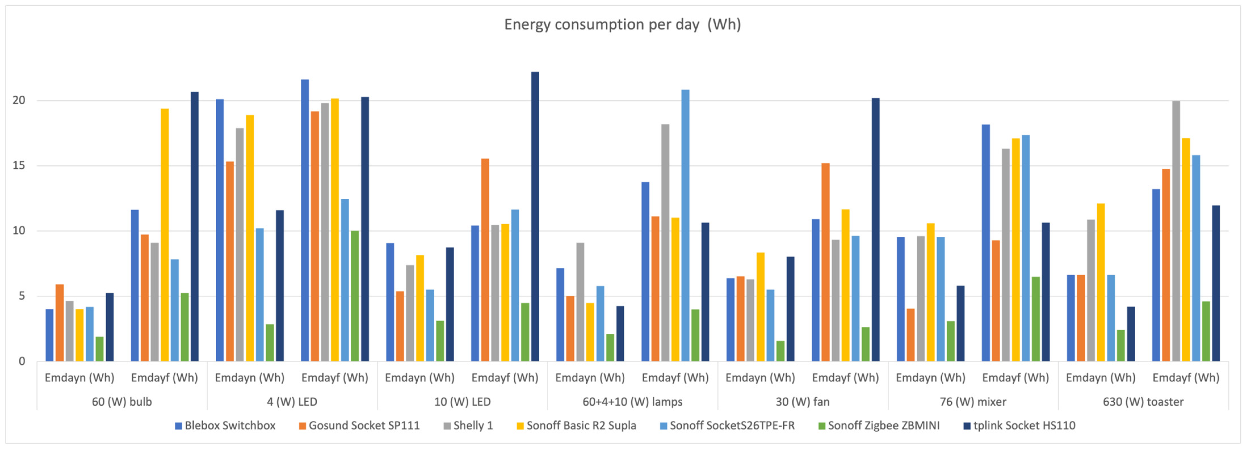
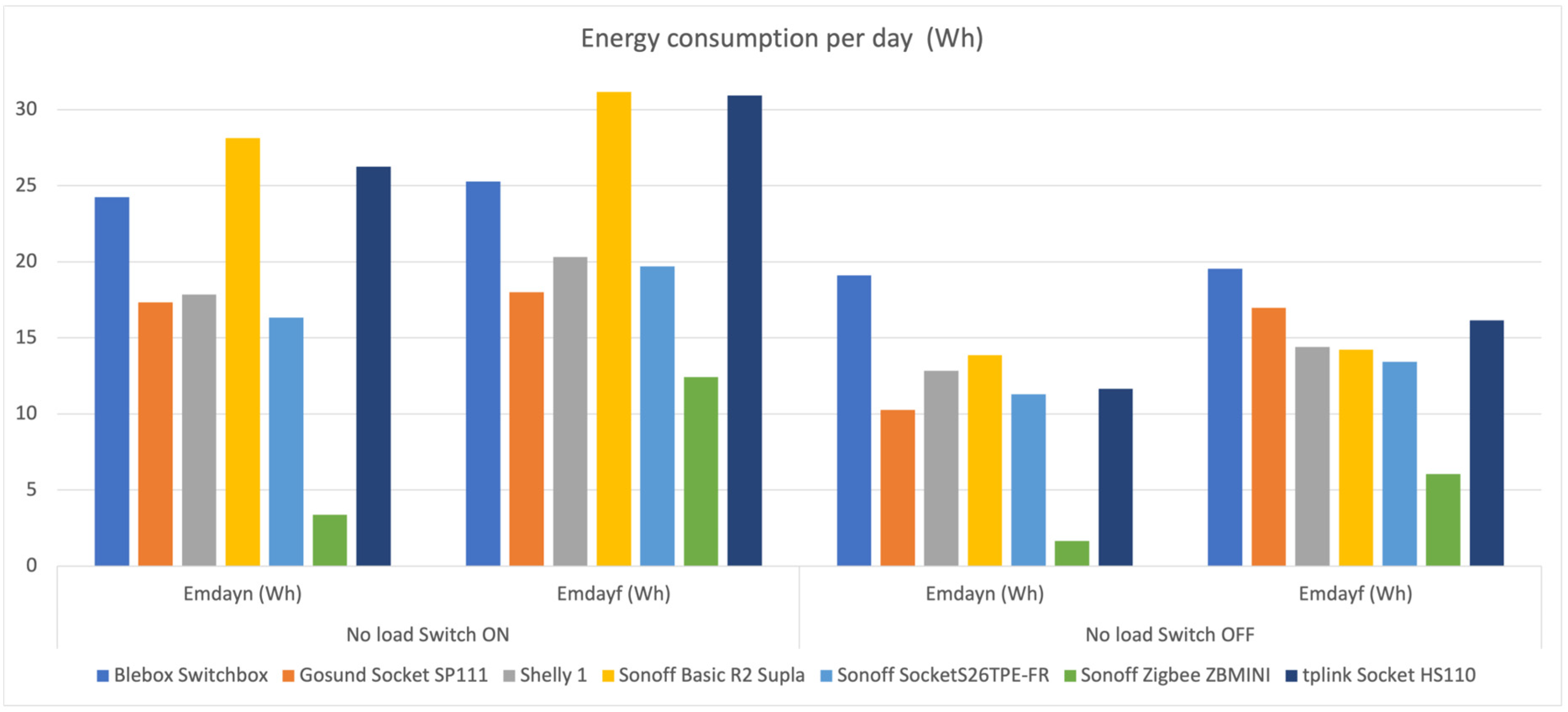
3.2. Analysis of Active Energy Consumption of Smart Home Modules
3.3. Verification of the Communication Quality of Smart Home Modules
4. Discussion
- Convenience and flexibility: wireless communication allows easy integration and control of various smart home modules from anywhere in the building using a smartphone or tablet.
- Fast installation: no need for wiring, and modules can be installed quickly and easily, which is especially beneficial for existing buildings.
- Scalability: wireless systems can be easily expanded with new modules and devices, which allows for gradual modernization and adaptation to changing needs.
- Interference: wireless communications may be susceptible to interference from other electronic devices or other wireless networks, which may affect signal reliability and quality.
- Range and connectivity: depending on the building and its structure, the range of the wireless network may be limited, which may lead to a loss of communication between modules.
- Dependence on technology: the functioning of smart home systems is most often based on the availability of a stable Internet connection, which may result in problems in the event of a network failure.
- Development of communication standards: the continuous development of wireless technologies, such as Wi-Fi 6 and ZigBee, creates the opportunity to improve the speed and reliability of communication.
- Integration with other technologies: wireless modules can be easily integrated with other technologies, such as the Internet of Things (IoT), allowing for more complex systems.
- Personalization: the development of artificial intelligence can enable more and more personalized experiences for users by adapting systems to their preferences and habits.
- Network security: wireless communication carries the risk of network attacks and security breaches, which may compromise privacy and system functionality.
- Power dependency: in the event of a power failure or battery problems, wireless modules may stop working, which can be especially critical in terms of safety.
- Privacy and data security: user data related to smart home modules may be exposed to threats related to cybercrime and privacy violations.
5. Conclusions
Funding
Data Availability Statement
Conflicts of Interest
References
- Froiz-Míguez, I.; Fernández-Caramés, T.; Fraga-Lamas, P.; Castedo, L. Design, Implementation and Practical Evaluation of an IoT Home Automation System for Fog Computing Applications Based on MQTT and ZigBee-WiFi Sensor Nodes. Sensors 2018, 18, 2660. [Google Scholar] [CrossRef] [PubMed]
- Kazeem, O.O.; Akintade, O.; Kehinde, L.O.; Akintade, O.O.; Kehinde, L.O. Comparative Study of Communication Interfaces for Sensors and Actuators in the Cloud of Internet of Things. Int. J. Internet Things 2017, 2017, 9–13. [Google Scholar] [CrossRef]
- Islam, R.; Rahman, M.W.; Rubaiat, R.; Hasan, M.M.; Reza, M.M.; Rahman, M.M. LoRa and Server-Based Home Automation Using the Internet of Things (IoT). J. King Saud Univ. Comput. Inf. Sci. 2022, 34, 3703–3712. [Google Scholar] [CrossRef]
- Li, W.; Wang, S. A Fully Distributed Optimal Control Approach for Multi-Zone Dedicated Outdoor Air Systems to Be Implemented in IoT-Enabled Building Automation Networks. Appl. Energy 2022, 308, 118408. [Google Scholar] [CrossRef]
- Ruiz-Zafra, A.; Benghazi, K.; Noguera, M. IFC+: Towards the Integration of IoT into Early Stages of Building Design. Autom. Constr. 2022, 136, 104129. [Google Scholar] [CrossRef]
- Yar, H.; Imran, A.S.; Khan, Z.A.; Sajjad, M.; Kastrati, Z. Towards Smart Home Automation Using IoT-Enabled Edge-Computing Paradigm. Sensors 2021, 21, 4932. [Google Scholar] [CrossRef] [PubMed]
- Ożadowicz, A. A New Concept of Active Demand Side Management for Energy Efficient Prosumer Microgrids with Smart Building Technologies. Energies 2017, 10, 1771. [Google Scholar] [CrossRef]
- Kiehbadroudinezhad, M.; Merabet, A.; Abo-Khalil, A.G.; Salameh, T.; Ghenai, C. Intelligent and Optimized Microgrids for Future Supply Power from Renewable Energy Resources: A Review. Energies 2022, 15, 3359. [Google Scholar] [CrossRef]
- Chinchero, H.F.; Alonso, J.M. Development of an IoT-Based Electrical Consumption Measurement and Analysis System for Smart Homes and Buildings. In Proceedings of the 21st IEEE International Conference on Environment and Electrical Engineering and 2021 5th IEEE Industrial and Commercial Power System Europe (EEEIC/I&CPS Europe), Bari, Italy, 7–10 September 2021; Institute of Electrical and Electronics Engineers Inc.: Piscataway, NJ, USA, 2021. [Google Scholar]
- Kawa, B.; Borkowski, P. Integration of Machine Learning Solutions in the Building Automation System. Energies 2023, 16, 4504. [Google Scholar] [CrossRef]
- Chivarov, S.; Kopacek, P.; Chivarov, N. Cost Oriented Humanoid Robot Communication with IoT Devices via MQTT and Interaction with a Smart Home HUB Connected Devices. IFAC-PapersOnLine 2019, 52, 104–109. [Google Scholar] [CrossRef]
- Lara, A.; Mayor, V.; Estepa, R.; Estepa, A.; Díaz-Verdejo, J.E. Smart Home Anomaly-Based IDS: Architecture Proposal and Case Study. Internet Things 2023, 22, 100773. [Google Scholar] [CrossRef]
- Hasan, M.; Biswas, P.; Bilash, M.T.I.; Dipto, M.A.Z. Smart Home Systems: Overview and Comparative Analysis. In Proceedings of the 2018 Fourth International Conference on Research in Computational Intelligence and Communication Networks (ICRCICN), Kolkata, India, 22–23 November 2018; IEEE: Piscataway, NJ, USA, 2018; pp. 264–268. [Google Scholar]
- Horyachyy, O. Comparison of Wireless Communication Technologies Used in a Smart Home: Analysis of Wireless Sensor Node Based on Arduino in Home Automation Scenario. Master’s Thesis, Faculty of Computing, Blekinge Institute of Technology, Karlskrona, Sweden, 2017. [Google Scholar]
- Filho, G.P.R.; Villas, L.A.; Gonçalves, V.P.; Pessin, G.; Loureiro, A.A.F.; Ueyama, J. Energy-Efficient Smart Home Systems: Infrastructure and Decision-Making Process. Internet Things 2019, 5, 153–167. [Google Scholar] [CrossRef]
- Balasingam, S.; Zapiee, M.K.; Mohana, D. Smart Home Automation System Using IOT. Int. J. Recent Technol. Appl. Sci. 2022, 4, 44–53. [Google Scholar] [CrossRef]
- Pirbhulal, S.; Zhang, H.; Alahi, M.E.; Ghayvat, H.; Mukhopadhyay, S.; Zhang, Y.-T.; Wu, W. A Novel Secure IoT-Based Smart Home Automation System Using a Wireless Sensor Network. Sensors 2016, 17, 69. [Google Scholar] [CrossRef] [PubMed]
- Kräuchi, P.; Dahinden, C.; Jurt, D.; Wouters, V.; Menti, U.-P.; Steiger, O. Electricity Consumption of Building Automation. Energy Procedia 2017, 122, 295–300. [Google Scholar] [CrossRef]
- Del-Valle-Soto, C.; Nolazco-Flores, J.A.; Del Puerto-Flores, J.A.; Velázquez, R.; Valdivia, L.J.; Rosas-Caro, J.; Visconti, P. Statistical Study of User Perception of Smart Homes during Vital Signal Monitoring with an Energy-Saving Algorithm. Int. J. Environ. Res. Public Health 2022, 19, 9966. [Google Scholar] [CrossRef] [PubMed]
- Noga, M.; Ożadowicz, A.; Grela, J. Modern, Certified Building Automation Laboratories AutBudNet–Put “Learning by Doing” Idea into Practice. Przegląd Elektrotechniczny (Electr. Rev.) 2012, 88, 137–141. [Google Scholar]
- SUPLA Open Software and Open Hardware. Available online: https://www.supla.org/en/ (accessed on 14 August 2023).
- Sonel PQM-711—Description and Tech Information. Available online: https://www.sonel.pl/en/product/power-quality-analyzer-sonel-pqm-711/ (accessed on 24 August 2023).
- Yang, H.; Kim, B.; Lee, J.; Ahn, Y.; Lee, C. Advanced Wireless Sensor Networks for Sustainable Buildings Using Building Ducts. Sustainability 2018, 10, 2628. [Google Scholar] [CrossRef]


| Module | Pnear_ON (W) | Qnear_ON (VAr) |
|---|---|---|
| Blebox Switchbox | 1.010 | −0.259 |
| Gosund Socket S111 | 0.722 | −0.106 |
| Shelly 1 | 0.744 | −0.025 |
| Sonoff Basic R2 Supla | 1.172 | −0.720 |
| Sonoff Socket S26R2TPE-FR | 0.680 | 0.045 |
| Sonoff ZigBee ZBMINI | 0.140 | −0.402 |
| tplink Socket HS110 | 1.094 | −0.043 |
| Module | Pfar_ON (W) | Qfar_ON (VAr) |
|---|---|---|
| Blebox Switchbox | 1.053 | −0.095 |
| Gosund Socket S111 | 0.750 | 0.160 |
| Shelly 1 | 0.846 | 0.035 |
| Sonoff Basic R2 Supla | 1.298 | −0.730 |
| Sonoff Socket S26R2TPE-FR | 0.821 | 0.119 |
| Sonoff ZigBee ZBMINI | 0.517 | −0.692 |
| tplink Socket HS110 | 1.289 | 0.030 |
| Module | Pnear_OFF (W) | Qnear_OFF (VAr) |
|---|---|---|
| Blebox Switchbox | 0.795 | −0.176 |
| Gosund Socket S111 | 0.427 | 0.006 |
| Shelly 1 | 0.535 | −0.031 |
| Sonoff Basic R2 Supla | 0.578 | −0.590 |
| Sonoff Socket S26R2TPE-FR | 0.470 | −0.017 |
| Sonoff ZigBee ZBMINI | 0.069 | −0.881 |
| tplink Socket HS110 | 0.485 | 0.033 |
| Module | Pfar_OFF (W) | Qfar_OFF (VAr) |
|---|---|---|
| Blebox Switchbox | 0.814 | −0.027 |
| Gosund Socket S111 | 0.707 | 0.155 |
| Shelly 1 | 0.600 | 0.137 |
| Sonoff Basic R2 Supla | 0.592 | −0.701 |
| Sonoff Socket S26R2TPE-FR | 0.559 | 0.148 |
| Sonoff ZigBee ZBMINI | 0.252 | −0.872 |
| tplink Socket HS110 | 0.673 | 0.298 |
| Module | Eadd_day_ON (Wh) | Eadd_yr_ON (kWh) |
|---|---|---|
| Blebox Switchbox | 1.03 | 0.38 |
| Gosund Socket S111 | 0.67 | 0.25 |
| Shelly 1 | 2.45 | 0.89 |
| Sonoff Basic R2 Supla | 3.02 | 1.10 |
| Sonoff Socket S26R2TPE-FR | 3.38 | 1.24 |
| Sonoff ZigBee ZBMINI | 9.05 | 3.30 |
| tplink Socket HS110 | 4.68 | 1.71 |
| Module | Eadd_day_OFF (Wh) | Eadd_yr_OFF (kWh) |
|---|---|---|
| Blebox Switchbox | 0.44 | 0.16 |
| Gosund Socket S111 | 0.48 | 0.18 |
| Shelly 1 | 1.56 | 0.57 |
| Sonoff Basic R2 Supla | 0.34 | 0.12 |
| Sonoff Socket S26R2TPE-FR | 2.14 | 0.78 |
| Sonoff ZigBee ZBMINI | 4.39 | 1.60 |
| tplink Socket HS110 | 4.51 | 1.65 |
| Module | Frequency (Mhz) | RSSI (dBm) | Data Throughput (Mbps) | Upload Data Rate (kbps) | Download Data Rate (kbps) |
|---|---|---|---|---|---|
| Blebox Switchbox | 2437 | −48 | 54 | 0.8 | 2.1 |
| Gosund Socket SP111 | 2412 | −44 | 54 | 0.9 | 1.2 |
| Shelly 1 | 2427 | −57 | 54 | 0.8 | 0.5 |
| Sonoff Basic R2 Supla | 2437 | −51 | 54 | 0.6 | 1.1 |
| Sonoff SocketS26TPE-FR | 2442 | −51 | 54 | 1.1 | 1.4 |
| Sonoff Zigbee ZBMINI | 2442 | −28 | 54 | 0.7 | 1.3 |
| tplink Socket HS110 | 2437 | −31 | 65 | 0.6 | 2.0 |
| Module | Frequency (Mhz) | RSSI (dBm) | Data Throughput (Mbps) | Upload Data Rate (kbps) | Download Data Rate (kbps) |
|---|---|---|---|---|---|
| Blebox Switchbox | 2437 | −76 | 48 | 0.4 | 1.6 |
| Gosund Socket SP111 | 2412 | −76 | 24 | 0.5 | 0.7 |
| Shelly 1 | 2427 | −81 | 36 | 0.3 | 0.2 |
| Sonoff Basic R2 Supla | 2437 | −77 | 18 | 0.6 | 0.7 |
| Sonoff SocketS26TPE-FR | 2442 | −77 | 48 | 0.6 | 0.7 |
| Sonoff Zigbee ZBMINI | 2442 | −76 | 36 | 0.5 | 1.0 |
| tplink Socket HS110 | 2437 | −71 | 58 | 0.5 | 1.9 |
| Module/Load | Active Power (W) | Operation Time (h) | Energy (Wh) | Module Total Energy Amount (Wh) |
|---|---|---|---|---|
| LED lamp 4 W | 4.00 | 8 | 32.0 | |
| Sonoff ZBMINI, relay ON | 0.43 | 8 | 3.44 | |
| Sonoff ZBMINI, relay OFF | 0.07 | 16 | 1.12 | Total: 4.56 |
| tplink socket, relay ON | 0.45 | 8 | 3.60 | |
| tplink socket, relay OFF | 0.48 | 16 | 7.68 | Total: 11.28 |
| Blebox Switchbox, relay ON | 0.44 | 8 | 3.52 | |
| Blebox Switchbox, relay OFF | 0.79 | 16 | 12.64 | Total: 16.16 |
| LED lamp 10 W | 10.0 | 8 | 80 | |
| Sonoff ZBMINI, relay ON | 0.59 | 8 | 4.72 | |
| Sonoff ZBMINI, relay OFF | 0.07 | 16 | 1.12 | Total: 5.84 |
| tplink socket, relay ON | 0.59 | 8 | 4.72 | |
| tplink socket, relay OFF | 0.48 | 16 | 7.68 | Total: 12.4 |
| Blebox Switchbox, relay ON | 0.58 | 8 | 4.64 | |
| Blebox Switchbox, relay OFF | 0.79 | 16 | 12.64 | Total: 17.28 |
Disclaimer/Publisher’s Note: The statements, opinions and data contained in all publications are solely those of the individual author(s) and contributor(s) and not of MDPI and/or the editor(s). MDPI and/or the editor(s) disclaim responsibility for any injury to people or property resulting from any ideas, methods, instructions or products referred to in the content. |
© 2023 by the author. Licensee MDPI, Basel, Switzerland. This article is an open access article distributed under the terms and conditions of the Creative Commons Attribution (CC BY) license (https://creativecommons.org/licenses/by/4.0/).
Share and Cite
Ożadowicz, A. Technical, Qualitative and Energy Analysis of Wireless Control Modules for Distributed Smart Home Systems. Future Internet 2023, 15, 316. https://doi.org/10.3390/fi15090316
Ożadowicz A. Technical, Qualitative and Energy Analysis of Wireless Control Modules for Distributed Smart Home Systems. Future Internet. 2023; 15(9):316. https://doi.org/10.3390/fi15090316
Chicago/Turabian StyleOżadowicz, Andrzej. 2023. "Technical, Qualitative and Energy Analysis of Wireless Control Modules for Distributed Smart Home Systems" Future Internet 15, no. 9: 316. https://doi.org/10.3390/fi15090316
APA StyleOżadowicz, A. (2023). Technical, Qualitative and Energy Analysis of Wireless Control Modules for Distributed Smart Home Systems. Future Internet, 15(9), 316. https://doi.org/10.3390/fi15090316