


An Efficient Adaptive Data-Link-Layer Architecture for LoRa Networks


Abstract
:1. Introduction
2. Related Work
3. LoRa Parameter Background
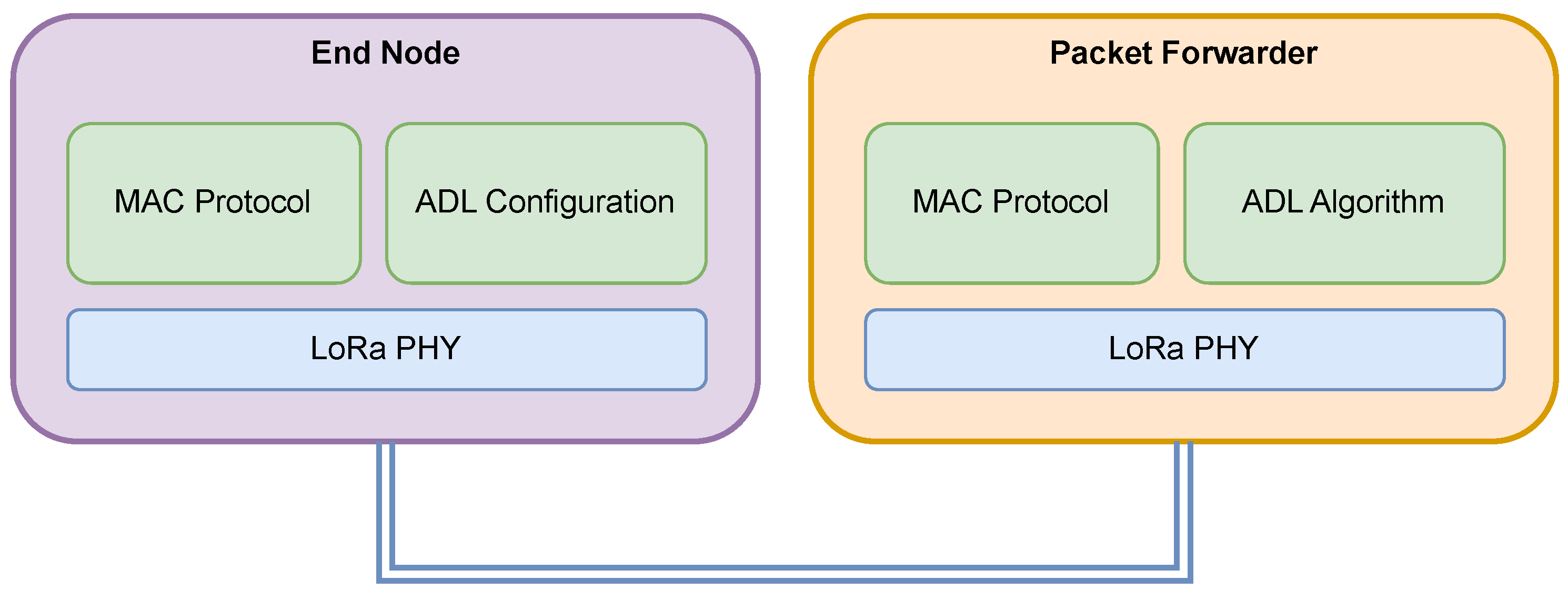
4. Data Link Layer Design
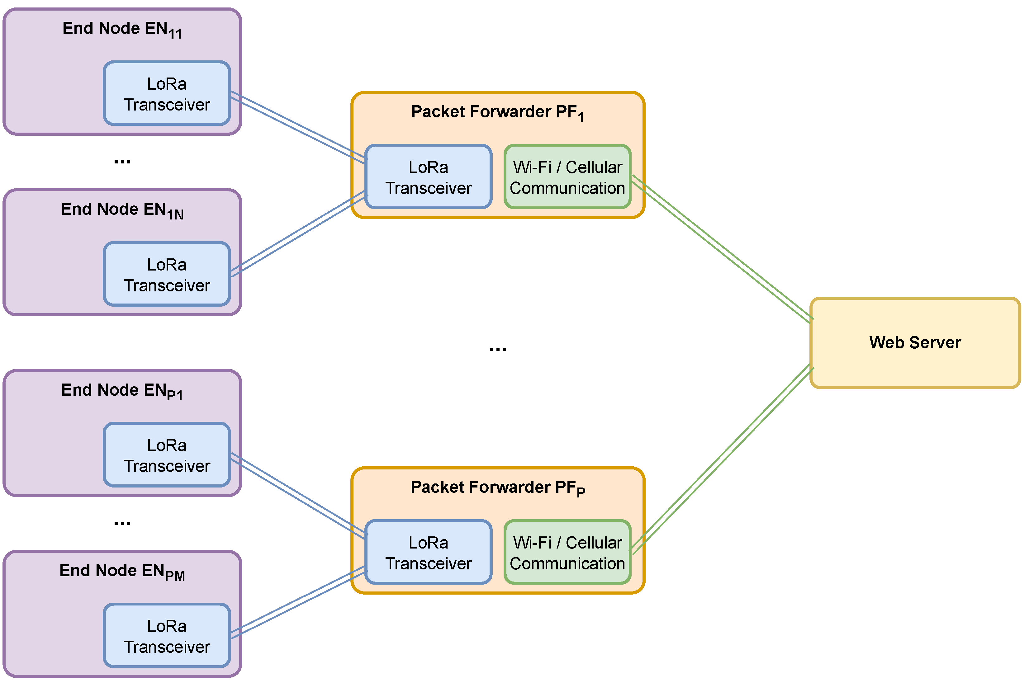
4.1. Network Topology
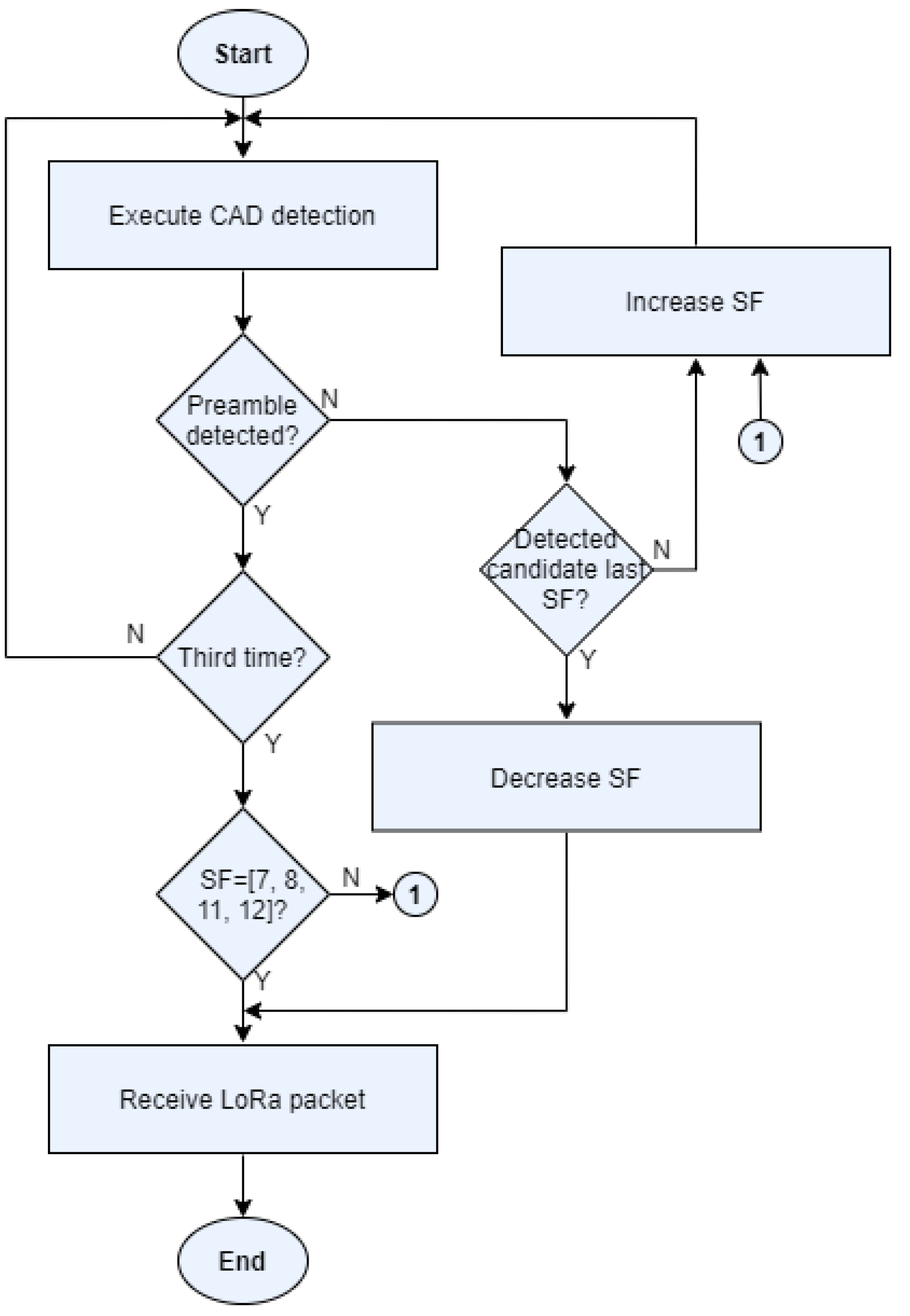
4.2. Adaptive SF Algorithm
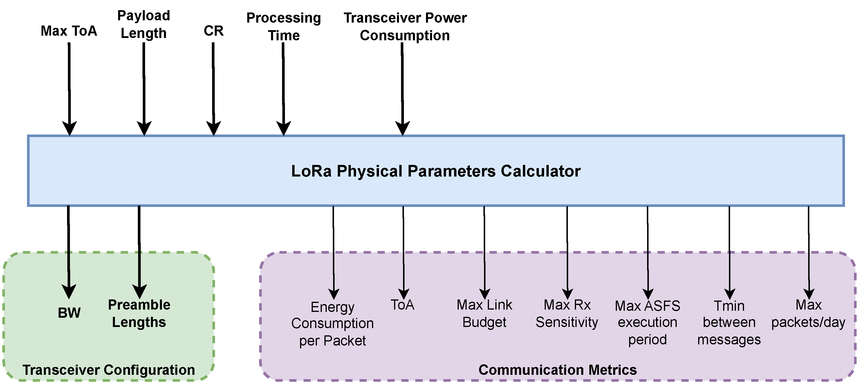
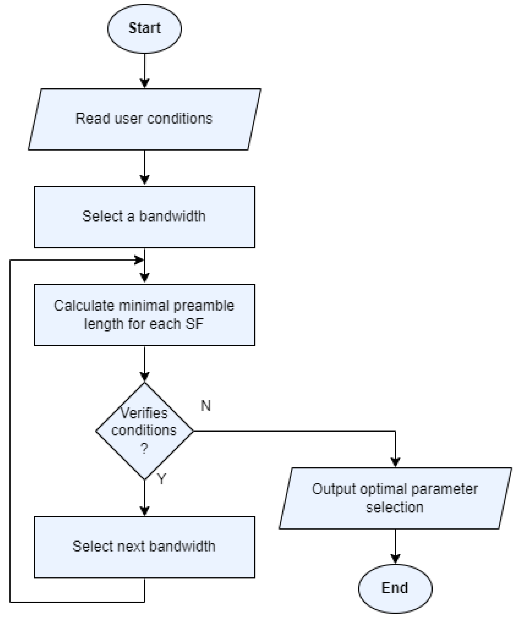
4.3. LoRa Parameter Calculator
4.4. MAC Protocol
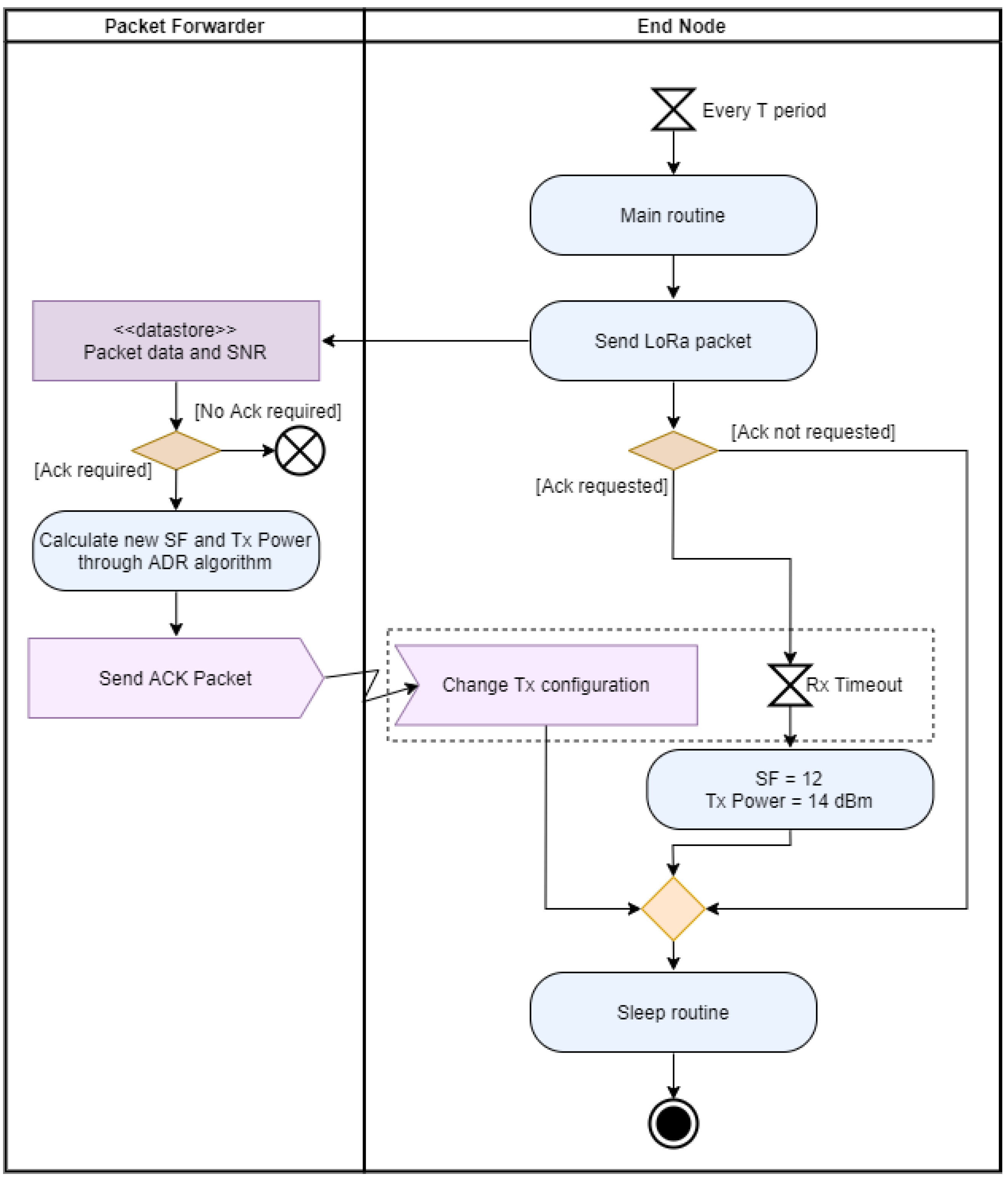
4.5. ADL Mechanism
5. Results and Discussion
6. Conclusions
Author Contributions
Funding
Data Availability Statement
Conflicts of Interest
References
- Mekki, K.; Bajic, E.; Chaxel, F.; Meyer, F. A comparative study of LPWAN technologies for large-scale IoT deployment. ICT Express 2019, 5, 1–7. [Google Scholar] [CrossRef]
- Semtech. LoRa and LoRaWAN: A Technical Overview. Available online: https://lora-developers.semtech.com/documentation/tech-papers-and-guides/lora-and-lorawan/ (accessed on 5 December 2022).
- LoRa Alliance. LoRaWAN 1.0.4 Specification Package. Available online: https://lora-alliance.org/resource_hub/lorawan-104-specification-package/ (accessed on 5 December 2022).
- Kenyeres, M.; Kenyeres, J. Average Consensus over Mobile Wireless Sensor Networks: Weight Matrix Guaranteeing Convergence without Reconfiguration of Edge Weights. Sensors 2020, 20, 3677. [Google Scholar] [CrossRef] [PubMed]
- Adefemi Alimi, K.O.; Ouahada, K.; Abu-Mahfouz, A.M.; Rimer, S. A Survey on the Security of Low Power Wide Area Networks: Threats, Challenges, and Potential Solutions. Sensors 2020, 20, 5800. [Google Scholar] [CrossRef] [PubMed]
- Ali, T.A.A.; Choksi, V.; Potdar, M.B. Precision Agriculture Monitoring System using Green Internet of Things (IoT). Int. J. Res. Appl. Sci. Eng. Technol. 2018, 6, 2961–2970. [Google Scholar] [CrossRef]
- Co, J.; Tiausas, F.J.; Domer, P.A.; Guico, M.L.; Monje, J.C.; Oppus, C. Design of a Long-Short Range Soil Monitoring Wireless Sensor Network for Medium-Scale Deployment. In Proceedings of the TENCON 2018—IEEE Region 10 Annual International Conference, Jeju, Republic of Korea, 28–31 October 2018; pp. 1371–1376. [Google Scholar]
- Nico, N.G. Development of Low-cost LoRaWAN Gateway for Private Deployments. Master’s Thesis, Instituto Superior Técnico, Lisbon, Portugal, November 2017. [Google Scholar]
- Xia, X.; Hou, N.; Zheng, Y.; Gu, T. PCube: Scaling LoRa Concurrent Transmissions with Reception Diversities. ACM Trans. Sens. Netw. 2022, 18, 66. [Google Scholar] [CrossRef]
- Wang, Y.; Zhang, F.; Zheng, X.; Liu, L.; Ma, H. Decoding LoRa Collisions via Parallel Alignment. ACM Trans. Sens. Netw. 2023, 19, 62. [Google Scholar] [CrossRef]
- Loubany, A.; Lahoud, S.; Chall, R. Adaptive algorithm for spreading factor selection in LoRaWAN networks with multiple gateways. Comput. Netw. 2020, 182, 107491. [Google Scholar] [CrossRef]
- Finnegan, J.; Farrell, R.; Brown, S. Analysis and Enhancement of the LoRaWAN Adaptive Data Rate Scheme. IEEE Internet Things 2020, 7, 7171–7180. [Google Scholar] [CrossRef]
- Islam, A.; Akter, K.; Nipu, N.J.; Das, A.; Rahman, M.M.; Rahman, M. IoT Based Power Efficient Agro Field Monitoring and Irrigation Control System: An Empirical Implementation in Precision Agriculture. In Proceedings of the 2018 International Conference on Innovations in Science, Engineering and Technology (ICISET), Chittagong, Bangladesh, 27–28 October 2018; pp. 372–377. [Google Scholar]
- Gloria, A.; Dionisio, C.; Simoes, G.; Sebastiao, P.; Souto, N. WSN Application for Sustainable Water Management in Irrigation Systems. In Proceedings of the IEEE 5th World Forum on Internet of Things (WF-IoT’19), Limerick, Ireland, 15–18 April 2019. [Google Scholar]
- Kim, S.; Lee, H.; Jeon, S. An Adaptive Spreading Factor Selection Scheme for a Single Channel LoRa Modem. Sensors 2020, 20, 1008. [Google Scholar] [CrossRef] [PubMed]
- Rahman, M.; Saifullah, A. Boosting Reliability and Energy-Efficiency in Indoor LoRa. In Proceedings of the 8th ACM/IEEE Conference on Internet of Things Design and Implementation (IoTDI ’23), San Antonio, TX, USA, 9–12 May 2023; pp. 396–409. [Google Scholar]
- Marjasz, R.; Połys, K.; Strzoda, A.; Grochla, K. Improving Delivery Ratio in LoRa Network. In Proceedings of the 19th ACM International Symposium on Mobility Management and Wireless Access (MobiWac ’21), Alicante, Spain, 22–26 November 2021; pp. 141–146. [Google Scholar]
- Gamage, A.; Liando, J.; Gu, C.; Tan, R.; Li, M.; Seller, O. LMAC: Efficient Carrier-Sense Multiple Access for LoRa. ACM Trans. Sens. Netw. 2023, 19, 44. [Google Scholar] [CrossRef]
- Semtech. LoRa Modulation Basics, AN1200.22. Available online: https://web.archive.org/web/20190718200516/https://www.semtech.com/uploads/documents/an1200.22.pdf (accessed on 10 March 2020).
- Semtech. Reading Channel RSSI during a CAD, AN1200.21. Available online: https://studylib.net/doc/18373650/an1200.21-reading-channel-rssi-during-a-cad (accessed on 24 February 2020).
- GitHub Repository. LoRa Air-Time Calculator. Available online: https://github.com/ifTNT/lora-air-time (accessed on 1 June 2020).
- Karl, H.; Willig, A. Protocols and Architectures for Wireless Sensor Networks; John Wiley & Sons: Hoboken, NJ, USA, 2007. [Google Scholar]


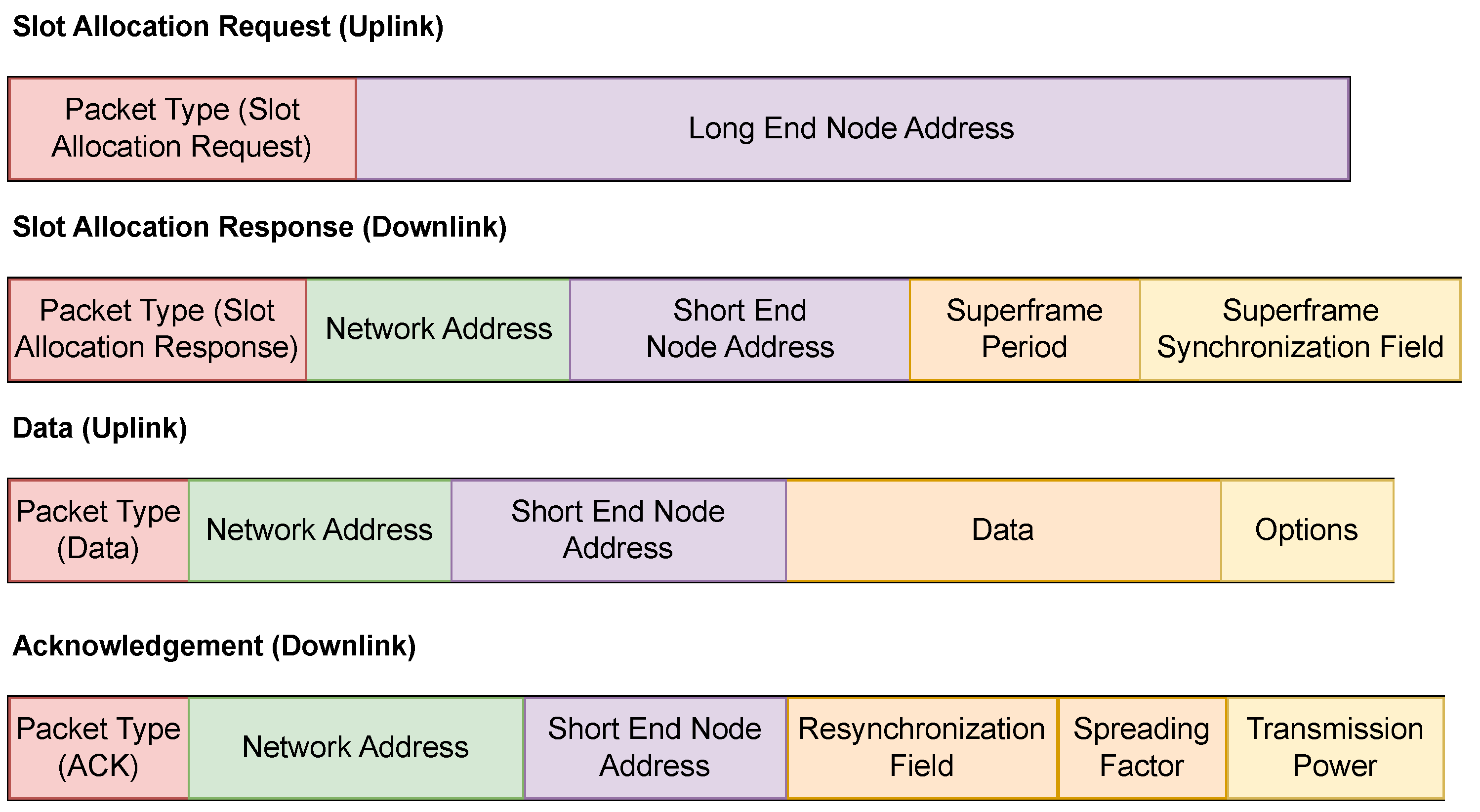
| Field Name | Length (bits) | Value |
|---|---|---|
| Slot Allocation Request (Uplink) | 4 | 0 × 0 |
| Slot Allocation Response (Downlink) | 4 | 0 × 1 |
| Data (Uplink) | 4 | 0 × 2 |
| ACK (Downlink) | 4 | 0 × 3 |
| Long End Node Address | 32 | 0 × 00000000–0 × FFFFFFFF |
| Network Address | 16 | 0 × 0001–0 × FFFF |
| Short End Node Address | 8 | 0 × 01–0 × FF |
| Superframe Period (s) | 16 | 0–65,535 |
| Superframe Synchronization Field (s) | 16 | 0–65,535 |
| Data (Payload) | 32 | Application-specific |
| Options | 4 | 0–1 |
| Metrics | T = 1000 ms | T = 4000 ms |
|---|---|---|
| Time on Air (ToA)—min|max (ms) | 97.5|925.7 | 406.5|3964.9 |
| Spreading Factor (SF)—min|max | 7|12 | 7|12 |
| Coding Rate (CR) | 4/5 | 4/5 |
| Bandwidth (Bw)—kHz | 125 | 31.25 |
| —min|max (ms) | 68.9|335.9 | 275.5|1343.5 |
| —min|max | 6|63 | 6|63 |
| Sensitivity—min|max (dB) | −121|−134 | −127|−140 |
| Max. Link Budget (dB) | −107|−120 | −113|−126 |
| Max. ASFS period (dB) | 132.1 | 528.4 |
| Min. time between messages—min|max (mm:ss) | 00:09|01:32 | 00:39|06:10 |
| Max. packets/day—min|max | 933|8857 | 217|2125 |
Disclaimer/Publisher’s Note: The statements, opinions and data contained in all publications are solely those of the individual author(s) and contributor(s) and not of MDPI and/or the editor(s). MDPI and/or the editor(s) disclaim responsibility for any injury to people or property resulting from any ideas, methods, instructions or products referred to in the content. |
© 2023 by the authors. Licensee MDPI, Basel, Switzerland. This article is an open access article distributed under the terms and conditions of the Creative Commons Attribution (CC BY) license (https://creativecommons.org/licenses/by/4.0/).
Share and Cite
Coutinho, M.; Afonso, J.A.; Lopes, S.F. An Efficient Adaptive Data-Link-Layer Architecture for LoRa Networks. Future Internet 2023, 15, 273. https://doi.org/10.3390/fi15080273
Coutinho M, Afonso JA, Lopes SF. An Efficient Adaptive Data-Link-Layer Architecture for LoRa Networks. Future Internet. 2023; 15(8):273. https://doi.org/10.3390/fi15080273
Chicago/Turabian StyleCoutinho, Micael, Jose A. Afonso, and Sérgio F. Lopes. 2023. "An Efficient Adaptive Data-Link-Layer Architecture for LoRa Networks" Future Internet 15, no. 8: 273. https://doi.org/10.3390/fi15080273
APA StyleCoutinho, M., Afonso, J. A., & Lopes, S. F. (2023). An Efficient Adaptive Data-Link-Layer Architecture for LoRa Networks. Future Internet, 15(8), 273. https://doi.org/10.3390/fi15080273