1. Introduction
In the last couple of years, the continuous development of the Internet has led to an unprecedented increase in the demand for telecommunication services from users. This increase has brought new challenges for operators and service providers, which have been forced to adapt new models and disruptive paradigms to accommodate the ever-increasing demand. These challenges include, among others, reducing development cycles and decreasing the speed needed to launch new services to the market; supporting their continuous update transparently to users to satisfy the constant demand for innovation; supporting the scalable operation of services by taking into account a high potential number of users, where an appropriate quality of experience must be delivered; etc.
In response to these challenges, cloud technologies, particularly the cloud-native model, have received great interest from the involved actors in the provision of Internet services. According to the Cloud Native Computing Foundation (CNCF) [
1], “
Cloud native technologies empower organisations to build and run scalable applications in modern, dynamic environments such as public, private, and hybrid clouds”. This model favours an application design based on microservice architectures [
2], in contrast to traditional approaches based on monolithic designs. By following a microservices approach, an application is developed as a set of small services communicated through simple, well-defined mechanisms, for example, based on HTTP. This model allows to overcome the inherent limitations of the monolithic design, where every application is developed as a single indivisible block, which requires more coordination between development teams, introduces further complexity in the updating processes, and does not allow to independently scale parts of an application.
In a cloud-native model, microservices can be executed in virtualisation containers [
3]. This allows a high degree of flexibility when deploying an application since containers are lightweight in comparison with traditional virtualisation platforms based on hypervisors. Containers can be exported to other virtualisation platforms with enough computational, networking and storage capacity to run them. Furthermore, they are able to pack the required software to execute every microservice independently from the rest since their own containers have all the software needed to run the service without the need for emulating an entire operating system. In the same fashion, containers offer a scalable solution that allows to flexibly adapt a service to its demand. For example, if an application experiences a sharp increase in traffic, new containers can be quickly deployed to provision for this demand, minimising service cut-offs. Given the rise in the popularity of container technology, there are several platforms that allow the management and orchestration of containers, both open source, such as Kubernetes (K8s) [
4], Docker Swarm [
5] or OpenStack [
6], as well as solutions offered by cloud providers, like Google Kubernetes Engine [
7] or Amazon Elastic Kubernetes Service [
8]. It is worth mentioning that K8s has become the most popular tool in the service cloud-native market. According to the 2021 survey of CNCF [
9], performed over the global cloud-native community (including software and technology, financial services, consultancy and telecommunication organisations), 96% of the surveyed reported the use of K8s in their organisation.
The rise of the cloud-native model has provided multiple benefits for the deployment of Internet services. However, microservice technologies have also been regarded as excellent candidates for the deployment of network functions in cloud-native environments for the next generation of mobile networks (5G and 6G). The network function virtualisation (NFV) paradigm has greatly assisted in the agile deployment and development of network services (NSes) in both cloud and edge environments. NFV aims at the softwarisation of network services and functionalities through the use of virtualisation technologies, such as virtual machines (VMs), reducing the deployment and development costs since it is not necessary to develop and maintain the dedicated hardware involved in the provision of some network functions. Naturally, containers have been regarded as the next step for the deployment of NSes under the NFV umbrella since their lightweight nature and easier management can enhance the provision of NSes in comparison with more computationally demanding solutions. Naturally, the provision of network services involve certain degree of orchestration between containers to ensure its proper functionality. In this regard, microservice platforms like K8s are excellent candidates for this purpose, thanks to their orchestration and abstraction tools (automated rollouts and rollbacks, self-healing properties, service discovery …) that assist in the swift and efficient deployment of NSes in data centre environments, allowing microservices to properly interact with each other to offer a complex application.
Some examples of NSes that could be deployed using NFV technologies include load balancing, service discovery and routing functionalities. All these services must be connected to one or several virtual networks able to isolate each VNF in different local area network (LAN) domains. This behaviour provides these functions with a finer control of their networking aspects within the platform where they are deployed, regardless of their location. These virtual networks are of the utmost importance for any NFV deployments since they enable isolation between different VNF instances at the network level to operate independently and securely, thus allowing to implement the VNF chaining necessary for the deployment of complex NSes.
Virtual networks are necessary for the deployment of NSes in cloud-native environments. However, microservice platforms, like K8s, usually take a hands-off approach towards the connectivity of container networking: the flat networking approach. In this model, all microservices are visible to each other at the network (IP) layer through the use of networking agents deployed over a platform. These communications are especially useful when the applications and workloads must communicate through application-based communications (i.e., using APIs to communicate with one another) since these mechanisms dissociate the network configuration from the application itself. This approach in turn can provide high availability and higher resilience to failures, and its implementation can benefit microservice-based applications in multiple ways (high availability, automatic service discovery, etc.).
Unfortunately, there is an important downside that could limit the deployment of NSes in microservice platforms, as this flat networking approach prevents the creation and management of virtual networks, which are necessary to interconnect all the VNFs that compose a NS. Since all microservices are able to “see” each other at the network layer, there is no isolation between them. In consequence, the VNF chaining needed cannot be performed. Therefore, it is impossible to effectively deploy NSes in microservice platforms that only implement a flat networking approach towards their connectivity, as they lack the necessary tools to create and manage the required virtual networks used in NFV deployments.
In order to address this limitation, this paper presents a networking solution that enables the link-layer connectivity of microservice platforms using software-defined networking (SDN) technology. More concretely, link-layer secure connectivity for microservice platforms (L2S-M) provides a programmable data plane that virtualised workloads can use to connect among each other at the link-layer level, enabling the establishment of point-to-point or multi-point links between workloads in a microservice environment. Furthermore, this paper also explores the potential of L2S-M to provide link-layer communications between workloads located in different clusters if they are managed by a microservice platform, or sites, which can be managed by other virtualisation platforms based on VMs. As a validation use case example, this paper presents a Smart Campus scenario, where L2S-M is deployed to communicate different campuses located in geographically distributed scenarios and managed using distinct virtualisation technologies/orchestration functions, implementing a content delivery network (CDN) service to provide multimedia content in a university environment.
2. Background
The world of telecommunications and services has recently experienced an unprecedented demand for more efficient, resilient and robust applications able to support the ever-increasing demand of consumers, thanks to the new services and solutions that have flourished under the umbrella of the 5th Generation of mobile networks (5G). In this regard, the traditional monolithic design used in the development of telecommunication services falls short in many aspects. Under this model, the functionality of a complex application is wrapped as a single program or process, usually running inside a single host able to have all the necessary resources to execute its modules and functionalities. This model has significant drawbacks that come with this design architecture: higher complexity, less adaptability (a change in one module can have effects in the entirety of the code), lower scalability and long-term support [
10]. To combat all these challenges that prevent the effective development of new telecommunication applications and services, microservices architectures have rose as a key enabler towards the development and deployment of scalable, resilient and cost-efficient applications. In this model, each application is split into individual modules that can be distributed among several hosts and architectures. In order to build a complex functionality, each module is able to communicate with each other regardless of their physical location, and they can operate independently of the rest of the services, as it will usually perform a single task [
11]. This model assists with all of the problems that come with monolithic applications since complexity can be alleviated by focusing on each module (i.e., not having to modify an entire program), and scalability is increased through the deployment of multiple copies of each module used in the provision of the service (as well as being distributed in multiple architectures).
Precisely due to this paradigm shift in application development, there is a conscious effort in applying novel virtualisation technologies to enable this transition since traditional virtualisation technologies (i.e., hypervisor-based solutions) use more resources than container-based technologies [
3]. Virtual machines rely on hypervisors, which are software programs that operate at the hardware level within a host: its purpose is the emulation of an entire operating system isolated from the host that they are running, including its kernel. Containers, on the other hand, use the core operating system in the host to execute some of their functionalities, while having a file system isolated from the host [
12]. Since containers require far fewer resources than a virtual machine, a single host is able to deploy a wider array of functionalities and applications, which in turn provides higher scalability, resiliency and efficiency in comparison with virtual machines [
3,
13,
14].
This performance improvement makes containers the perfect candidate for the implementation of distributed architectures for the implementation and deployment of applications within the 5th generation of networks. With this idea in mind, there have been conscious efforts to apply container technology for the deployment of network functions and verticals, for instance, in [
14], where the authors define an application/service development kit (SDK) for the deployment of NFV-based applications for both hypervisor-based and containerised approaches. In [
15], the authors build a lightweight docker-based architecture for virtualising network functions to provide IoT security (although VNFs were connected using standard Docker network capabilities).
One fundamental aspect of container-based environments is guaranteeing that these containers are provided with a functional network interface, which enables the communication between microservices and other elements or devices outside (for example, devices connected to the Internet). In this regard, CNCF provides the container network interface (CNI) solution [
16], a specification and a set of libraries to provide a reference framework to develop plugins that allow the configuration of network interfaces for containers. Currently, this reference framework has been adopted by multiple container management solutions, such as the case of K8s, which supports multiple plugins for a wide arrange of networking plugins for microservice platforms: Flannel [
17], Calico [
18] or Multus [
19] are some of the most widely known (and utilised) in K8s. In consequence, the CNI model eases the addition of network interfaces in containers, allowing the connectivity between containers through their respective network interfaces. This connectivity model is clearly appropriate for microservice-based applications, where all of them must be able to communicate between each other (due to their intrinsic design, described in previous paragraphs).
Naturally, microservice platforms tend to use this CNI solutions to define how the different microservices interact between each other. In this regard, K8s explicitly state that every pod, the minimal computation unit that can be deployed in K8s composed of one or more containers (sharing a common network namespace), must have its own IP address, so it is not necessary to explicitly build links between pods. Moreover, K8s imposes the restriction that all pods deployed in any networking implementation must be able to communicate with all other pods on any other node without the use of network address translation (NAT) functionalities.
Regarding the logical interactivity of the services running within a microservice platform, although CNI plugins enable the network connectivity of the containers that are deployed over a cluster (as it was explained beforehand), they do not define how each of the microservices interact with each other using these communications, i.e., they do not implement the networking logic that a module (or set of modules) must have in order to provide the functionality of a complex application, or its relation with each module. For this reason, microservice platforms usually rely on the service mesh concept to connect different services (networking abstractions that can integrate one or several microservices, usually of the same type) and define how each microservice communicates within an infrastructure. Service mesh solutions like istio [
20] and Envoy [
21] use proxy functionalities that build a data plane between the microservices over a cluster, and use these functions to filter traffic and apply policies to the data sent to/from the proxies. This service mesh has its limitations, however, as it does not provide isolation between microservices since it only modifies routing information in a host, so the flat network implemented with the CNIs is still present regardless (i.e., all microservices can still see each other at the network (IP) level).
However, although this connectivity model is appropriate for applications, it is important to mention that it presents some limitations when deploying NFV services. In the NFV paradigm, services are deployed as sets of VNFs interconnected through virtual networks. These virtual networks provide the abstraction of point-to-point or multi-access links to the VNFs: they allow two or more VNFs to effectively connect to a single link-layer network, sharing a single broadcast domain, where all connected VNFs can be seen as ‘neighbours’ at a single IP hop distance. Furthermore, the traffic transmitted over a virtual network is not accessible to VNFs and entities outside the virtual network. Under the previous considerations, the connectivity model between cloud-native platforms presents some difficulties to support the abstraction offered by virtual networks commonly used in NFV ecosystems.
Despite these limitations, the integration of cloud-native technologies in the NFV ecosystem can present important advantages. Among others, we can mention the following: (a) the use of lightweight containers, portable and scalable, and the use of continuous integration and continuous deployment (CI/CD) methodologies, offering a solution to tackle the development and deployment of NFV services in microservice platforms; (b) the immense popularity of the cloud-native model and its adoption state, both in development and production environments, opens up new opportunities to the incorporation of developers, manufacturers and cloud service providers into the NFV market, which will positively impact the innovation process and the flexibility of options for service deployment—additionally, the access to a vast catalogue of virtual functions, developed through the cloud-native model, would be enabled for the provision of NFV services of aggregated value; and (c) the current initiatives to translate cloud-native technologies to edge environments, like the cases of KubeEdge [
22], OpenYurt [
23] or K3s [
24], centred around the use of K8s. These initiatives represent a promising alternative to have potentially limitless computation, storage and networking resources for the automatic deployment of operator services and verticals in the future.
Even though the flat networking approach has been the de facto standard in microservice platforms, some CNI solutions have tried to go beyond this model to provide networking functionalities similar to the ones implemented in other virtual infrastructure manager (VIM) solutions. For example, the OpenShift SDN network plugin [
25] allows the isolation of pods at the project level and the application of traffic policies, which can help with isolating workloads in a cluster (although they will still see each other at the network level, and it is only available for OpenShift clusters). The Nodus network controller [
26] enables the creation of subnetworks that pods can use to enable their connectivity in a K8s cluster. However, this subnetting is limited since the subnetworks are all located in the same IP range, so pods are not completely isolated within a K8s cluster. The Kube-OVN CNI plugin [
27] implements an OVN-based network virtualisation with K8s, which allows the creation of virtual subnetworks (not dependent on a single IP address range, contrary to the Nodus solution) that pods are able to attach to. This solution has its limitations however, as it does not allow the implementation of traffic engineering policies to route traffic between pods, it is not compatible with physical networking devices in a K8s clusters, and its inter-cluster capabilities is limited (it can only connect workloads at the network level).
The open-source software community is taking the first steps towards the evolution of networking models in cloud-native technologies, as well as adapting them to the NFV ecosystem. As an example, the ETSI Open Source MANO (OSM) project [
28], whose main objective is developing a management and orchestration platform for NFV environments in accordance to the ETSI standards, has supported the deployment of virtualised functions in K8s clusters since its SEVEN release. Nevertheless, this support is limited since it does not enable the creation of virtual links (VLs) to enable the isolated connectivity of different Kubernetes-based VNFs (KNFs) in a NS, as K8s does not natively provide a networking solution for creating virtual networks (i.e., OSM only deploys KNFs but does not define their connectivity, and all KNFs can communicate with each other). This is an important step towards the integration of NFV in microservice platforms since the management of VLs (usually represented as virtual networks) is a fundamental aspect for the effective deployment of NSes, as seen in works like [
29], where the authors perform a comprehensive analysis of NFV systems and deployments, or [
30], where the authors explain in detail the use of virtual networking and its performance impact depending on the virtual link types. In this regard, the interest of the research community in closing the gap between NFV and microservice platforms can be seen in such works as [
31], where the authors propose an architecture based on the monitoring, analysis, planning, and execution (MAPE) paradigm for the optimisation of network service performance to guarantee quality of service (QoS) in NFV environments, including container-based solutions, such as Docker and Kubernetes. Similarly, another example of this effort can be seen in the work [
32], where authors propose an implementation of a novel framework that enables the optimal deployment of contained-based VNFs, using a multi-layer approach based on monitoring and analysing data from the physical, virtual and service layers.
There have also been proposals to enhance the networking of microservice platforms in the NFV context. One prominent example is the network service mesh (NSM) [
33]. NSM offers a set of application programming interfaces (APIs) that allow the definition of network services (for example, an IP router, a firewall or a VPN tunnel), and establishes virtual point-to-point links between pods that want to access determined network services and pods that implement such services. NSM is designed to provide its connectivity service in scenarios with multiple clusters or cloud infrastructures, keeping the CNI solution used in every cluster. NSM presents a promising approach for exploiting the potential of cloud-native technologies in an NFV ecosystem. In such an ecosystem, NSM would provide the abstraction of a network service. For example, if a VNF offers an IP routing service, NSM would allow the establishment of virtual point-to-point links among this VNF and the remaining VNFs that must have IP connectivity with the former, depending on the NFV service to be deployed. However, this connectivity service does not provide the versatility of a virtual network. On the one hand, NSM does not allow to connect multiple VNFs into a single link-layer network in such a way that they can share a single broadcast domain (i.e., NSM does not offer the multi-access link abstraction). This aspect can be a limiting factor to deploy telecommunication or verticals services in an NFV ecosystem. On the other hand, the NSM APIs do not offer an open interface that allows the cloud infrastructure administrator to flexibly manage the existing virtual links. Following the previous example, it could be desirable to change the configuration of a point-to-point link in such a way that it terminates in another IP router instance in order to support load balancing; mirroring port configurations could be required to monitor data traffic transmitted over a link; or the temporary shutdown of certain links and their subsequent activation could be needed when managing a security incident; etc.
3. Virtual Networking for Microservice Platforms: L2S-M
3.1. Problem Statement
Due to the intrinsic nature of cloud-native environments, applications are developed and deployed with the following principles of architectural patterns: scalability since applications should be able to increase or decrease their performance based on demand and cost effectiveness; elasticity, as applications should be able to dynamically adapt their workloads to react against the possible changes in the infrastructure; and agility, as applications should be deployed as fast as possible to minimise service down times. In principle, an application should be able to be deployed over a distributed cloud in such a way that it can provide its service without any, or minimal, disruptions, while also adapting its performance (and distribution) to the demand and available resources in an infrastructure [
2]. One prominent case that focuses on this philosophy is microservice platforms: each function is composed of several modules (usually implemented as separate containers, as described in previous sections) that interact with each other to execute a complex functionality for one (or sometimes several) applications. These modules might not be deployed in the same infrastructure, physical equipment or virtual machine: it is usual that they are distributed across multiple geographical locations, or even spread across multiple clouds managed by different service providers. This model is an antithesis of the monolithic design (i.e., a single application with all its components embedded in its code), and it provides several advantages over its counterpart: high availability since a module might have several copies distributed over the cloud; resilience since a failure in one module does not compromise the entire functionality of the application; and shorter development and deployment cycles.
Taking into account the main characteristics of cloud-native environments, it is essential to define the networking between applications and modules to allow for seamless connectivity without compromising any of the benefits of the microservice model. In order to preserve such advantages, most solutions rely on a flat networking approach that facilitates communication among deployed functions and modules across different clouds, independently of the physical location and network configurations [
17,
18]. In this model, each microservice is able to reach at the IP level all of the containers that are deployed within an infrastructure. By using this approach, high-level APIs, such as RESTful APIs, can be implemented to enable the exchange information between functions (since all containers are connected between each other, their proper communication can only be guaranteed through application-layer mechanisms).
Naturally, in order to effectively implement a complex application, it is essential that networking solution enables external connectivity for some of its modules (containers). As it usually is not possible to directly send data to a particular container from outside a microservice platforms, platforms like K8s rely on networking abstractions to enable its connectivity from the outside. In this regard, K8s relies on K8s Services to expose its own pods to the exterior. For this purpose, K8s uses a Service API to define a logical set of endpoints (usually these endpoints are pods) to make those pods accessible within the platform. Then, the own K8s distributes this incoming traffic to each pod. Furthermore, some CNI plugins (like Calico [
18]) also implement some mechanisms to filter traffic for/to the pods, for instance, defining network policies that filter out undesired traffic (at the application layer).
It is clear that this model has its advantages in cloud-native environments: as applications might not be permanently deployed in a single node or cloud (either due to its unavailability or to optimise resources), a flat networking approach allows communication with/to an application regardless of its distribution and IP addressing. Furthermore, this model allows application developers to pass over the inner networking being performed in an infrastructure since it is completely transparent to the applications themselves. In other words, developers can assume that other modules of an application will always have connectivity, and that no further configurations should be required in the modules to be used in the infrastructure.
Despite its advantages, this model might not be suitable for all the services that could be provided through cloud-native platforms. In a previous work, we realised the potential of microservice platforms [
34] as enablers for the deployment network and vertical services in the context of the 5th and 6th generations of mobile networks (5G/6G) in cloud-native environments (particularly, microservice platforms, which are a subset of functions in the cloud-native model). Microservice platforms, like Kubernetes (K8s), usually employ container technology to build applications in their managed infrastructures. Due to their lightweight nature, in some environments (e.g., resource constrained scenarios), these platforms have multiple benefits over traditional virtualisation solutions like OpenStack, which usually require more resources for the management and deployment of NSes. However, due to the intrinsic nature of NSes, it is necessary to ensure that communication at the lower layers is available (and not just at the application layer) for the functions that build the service.
One prominent example of the necessities of virtual networking can be seen in the implementation of a router functionality. A traditional router must analyse incoming packets at the IP level from one of its network interfaces in order to check the destination that will be forwarded. However, this functionality can only be performed if each one of its interfaces is located in a different LAN. The same situation is present when dealing with virtual networks: in virtual networks, each function is located at different LANs (despite their geographical location) and a router functionality would have one interface in each virtual network, enabling the analysis of the incoming/outgoing packets to be forwarded to the corresponding functions located in different (isolated) virtual networks. In consequence, functions are isolated between each other at the network level and can only communicate through the corresponding router, which enables the secure deployment and isolation of network functionalities, as well as their chaining (necessary for NS implementations).
However, this behaviour is impossible to achieve in flat networking approaches: if all the functionalities are located in the same LAN (like they are in the flat networking approach), then there is no isolation between functions since they are in the same network domain, so the router cannot “decide” the routing/forwarding of the incoming/outgoing packets to each function. Hence, this problem heavily hinders the implementation of networking services in cloud native to host NSes in one, or several, clouds.
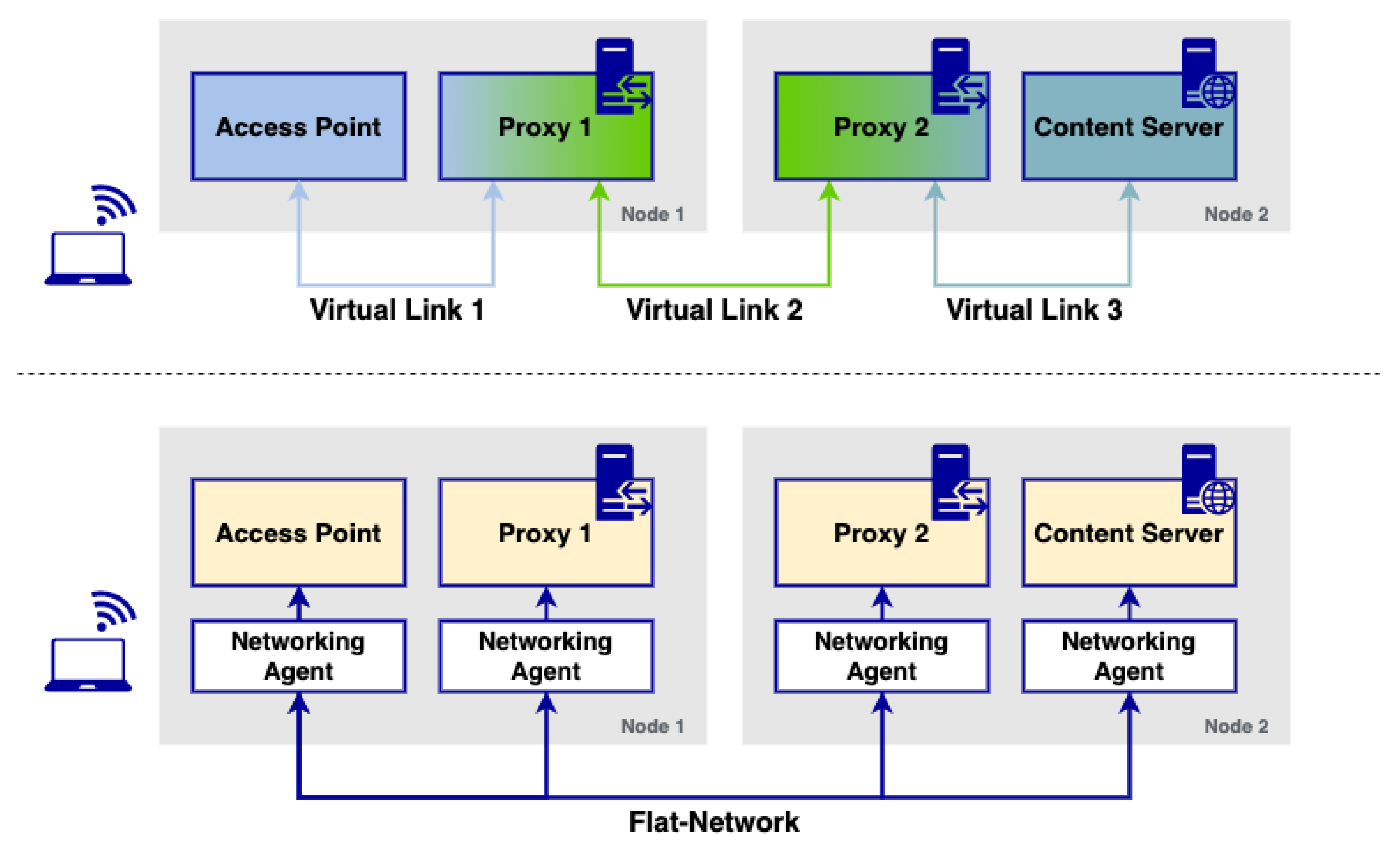
To further illustrate the issue that microservice platforms have for the implementation of NSes in cloud environments,
Figure 1 showcases a logic implementation of a multimedia content delivery service, in particular, a simple content delivery network (CDN) service. This CDN has two HTTP proxies: the first one is utilised to cache the content sent from a multimedia server, which allows to make the content closer to the end users (reducing download times and bandwidth used in the network) while the second one is a firewall that filters undesired requests from a function outside the CDN. Ideally, a service of such characteristics must enable sending the requests from/to the corresponding proxies and servers involved in the CDN, following the schema depicted in the upper side of the figure. Furthermore, the HTTP proxy must be able to analyse incoming packets at the network layer to appropriately filter undesired requests. Implementing services like the one depicted in this example is often performed in cloud environments through virtual links (i.e., virtual networks) that enable the isolated communication of different modules, which can only reach the corresponding peers of a particular virtual network. This enables the creation of links between functions similar to the ones that are used in NSes in the context of NFV, enabling the connectivity of microservices in schemas like the one shown in the upper part of the figure.
Unfortunately, due to the intrinsic behaviour of the networking model used in microservice platforms, an implementation of such characteristics is impossible to achieve. As it is depicted in the bottom part of the figure, microservice platforms with flat networking approaches do not isolate these components: all of them are able to see each other at the network level, usually through a set of networking agents in charge of forwarding traffic to the rest of the components deployed over the platform. Although these agents can usually discriminate traffic based on some protocols (normally application-layer based), they do not completely isolate these components between them since they all are reachable at the IP layer.
With the drawbacks of flat networking approaches in microservice platforms in mind, this paper presents a solution that enables the use of virtual networking for the deployment of network services and verticals in cloud-native environments: L2S-M. L2S-M aims at the provision of secure link-layer connectivity to NSes in cloud-native environments. Instead of being developed as a full networking solution to replace established connectivity solutions in different microservice platforms, L2S-M provides a flexible complementary approach to allow containers present in a cloud to attach into a programmable data plane that enables point-to-point or multi-point link-layer connectivity with any other container managed by the platform, regardless of its placement inside the infrastructure. This programmable data plane relies on software-defined networking (SDN) techniques to ensure the isolation of the link-layer traffic exchanged between containers. Moreover, SDN allows the application of traffic engineering mechanisms over the programmable data plane based on several factors like traffic priority or delay.
3.2. Functional Design of L2S-M
In our previous work [
35], L2S-M was first introduced as a complementary networking service to enable the deployment of NSes in NFV infrastructures (NFVIs) composed of resource-constrained environments (particularly, aerial microservice platforms based on K8s, as it is the de facto microservice platform and the one that could provide significant advantages in comparison with other VIMs [
34] in UAV networks). In this regard, L2S-M was created to address the limitations that NFV Orchestration could have in such scenarios as seen in our previous works [
36,
37]. Particularly, L2S-M enables the creation of virtual networks that could connect different VNFs at the link-layer level, which is essential to ensure the deployment of NSes for aerial networks (as seen in our previous works like [
38]). Moreover, the use of SDN could allow modifying the paths that traffic could use in aerial ad hoc network scenarios in response to sudden cut-offs, instead of leaving this task to the routing protocol in an aerial network.
However, it is clear that there is a need for bringing virtual networking solutions in cloud and edge microservice-based platforms, which is necessary to ensure the proper provision of applications and services in the form of cloud network functions (CNFs), particularly in K8s platforms. The flexibility of its design allows L2S-M to not interfere with standard networking models already implemented in microservice platforms, such as K8s, bringing a complementary solution instead that can be exploited by any developers/platform owners interested in deploying CNFs in microservice platforms. Moreover, L2S-M also has the potential to enable secure link-layer connectivity between several cloud and edge solutions, effectively enabling inter-site communications for network functions and verticals deployed over multiple infrastructures. With these ideas in mind, this paper showcases the design of L2S-M as a cloud-native solution that enables the management of virtual networks in microservice platforms. Particularly, this paper presents a full architectural design of this solution, envisioned as a K8s operator used in data centre infrastructures that, due to its flexibility, can be exported to other kind of scenarios (e.g., edge environments). This work presents an implementation of L2S-M as a K8s operator in order to detail its functionality in the well-known microservice platform (although it can be exported to any microservice platform).
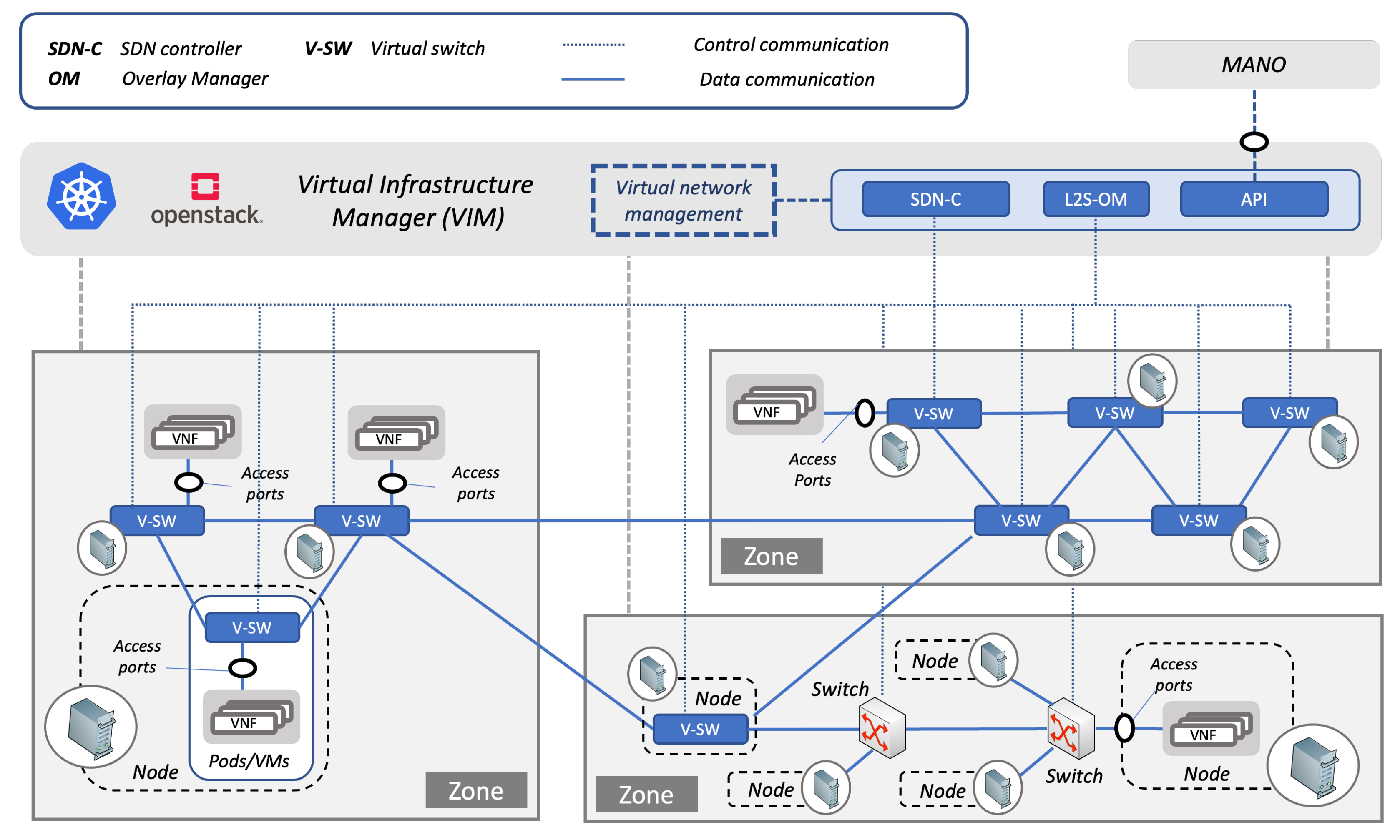
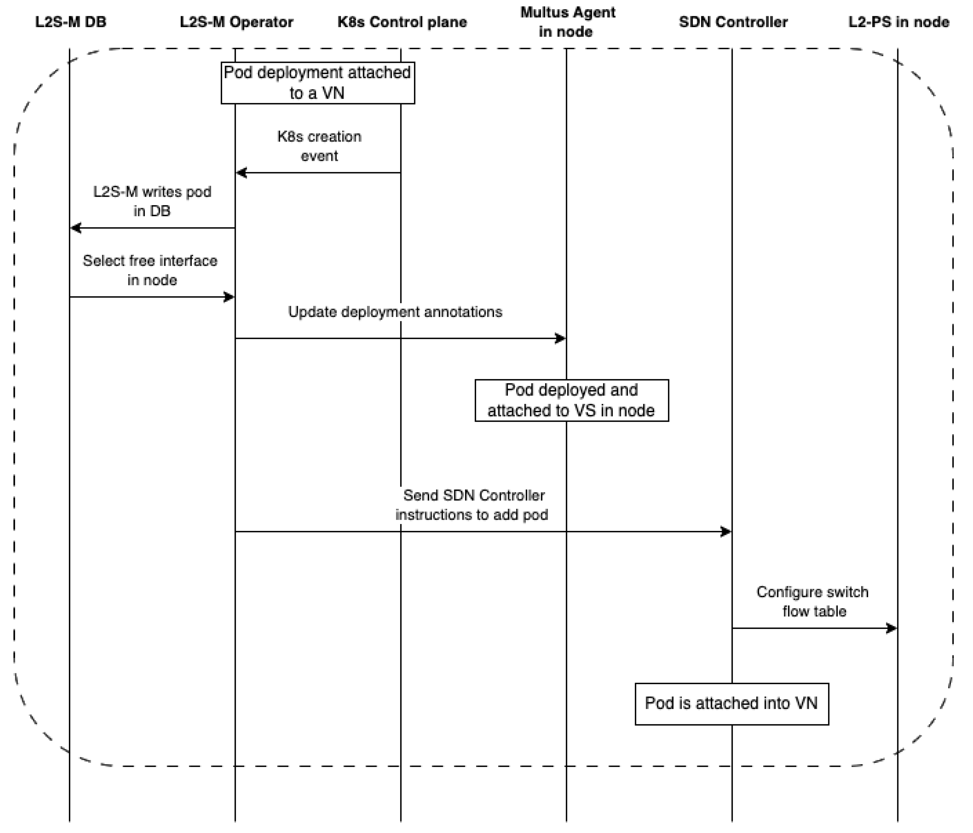
Figure 2 showcases the design of L2S-M in a cloud infrastructure. L2S-M delivers a programmable data plane that applications and services can use to establish point-to-point or multi-point links between each network function on demand. This objective is achieved through the creation and management of virtual networks, to which applications are able to attach, sharing the same broadcast domain between all the containers that joined one of these virtual networks, i.e., all containers will see each other in the same fashion as if they were in the same local network, regardless of their physical location within a cluster (set of machines governed by the same cloud-native management platform). This behaviour enables the direct point-to-point and multi-point link-layer communication between each container, isolating the traffic from each network to avoid unnecessary traffic filtering (for example, by having to implement multiple traffic policies for each application) and to ensure their secured operation.
The way that L2S-M is able to introduce this virtual networking model is through a set of programmable link-layer switches spread across the infrastructure as seen in
Figure 2. These switches can either be physical equipment (labelled as Switch in the figure (such as the ones that can be found in traditional data centre infrastructures)) or virtual switches (labelled as V-SW in the figure), which can take advantage of the benefits of container virtualisation technology. In order to establish the point-to-point links between the switches to allow their communications and enable the desired in the cluster, IP tunnelling mechanisms are used, for instance virtual extensible LANs (VXLANs) [
39] or generic routing encapsulation (GRE) [
40]. That way, the basis of the L2S-M programmable data plane is established through this infrastructure of switches.
Figure 2 showcases an infrastructure that divides three different availability zones with different characteristics. For example, one has physical switches that could be used to deploy hardware-accelerated functionalities, while another zone is an edge with resource-constrained devices like UAVs.
It is worth mentioning that most networking solutions in cloud-native environments also rely on IP tunnelling mechanisms to build their communications ‘backend’. However, there are noticeable differences with respect to the approach used in L2S-M: first of all, these solutions build the IP tunnels to interconnect their own networking agents, which perform routing tasks in host IP tables themselves, and can interfere with the networking of some machines and/or functions (and cannot be easily modified) in turn. Furthermore, these tunnels are built between all members of a cluster to build a mesh, while L2S-M has the flexibility to allow the use of any kind of topology and can be dynamically adapted depending on the necessities of the platform owners.
This overlay of programmable link-layer switches serves as the basis for the creation of the virtual networks. In order to provide the full programmable aspect of the overlay, L2S-M uses an SDN controller (SDN-C in the figure) to inject the traffic rules in each one of the switches, specifying which ports must be used in order to forward, or to block, the corresponding traffic coming from the containers attached to the switches and/or other members of the overlay. This SDN controller can also be embedded into the own virtualisation infrastructure as shown in
Figure 2. The use of this SDN approach can also enable the application of traffic engineering mechanisms to the traffic distributed across the programmable data plane. For instance, priority mechanisms could be implemented in certain services that are sensitive to latency constrains.
Service mesh solutions like Istio [
20] could be seen as alternatives that would enable a similar behaviour as the one provided by L2S-M. However, the service mesh was developed with the same ideas and concepts as the flat networking approach: instead of managing the network interfaces directly, service mesh solutions use proxy functionalities to forward/block traffic based on networking services (network abstractions) in a separate data plane from the one presently used in the cluster, basing its routing/forwarding in their logical definition (i.e., the user defines which services must communicate with each other). Although this is a favourable approach to provide high availability and keep the abstraction models present in the microservice platforms, this solution still does not address the isolation aspects needed for NFV deployments since all their containers are still located in the same LAN domain (through its CNI Plugin agents) and can be directly reached by the rest of the containers. Therefore, L2S-M provides a behaviour that service mesh cannot provide, as it does not have the proper tools to enable the use of virtual networks needed in NFV deployments.
It is true that other solutions have explored similar virtual networking concepts in microservice platforms, highlighting Nodus [
26] and Kube-OVN [
27]. However, all these solutions have tried to implement a substitute for current CNI plugins, while L2S-M provides this behaviour as a complementary solution for those applications that may require such a degree of networking control. Furthermore, L2S-M has been designed to enable its seamless use with physical switching infrastructures (commonly found in data centre networks) through single root input/output virtualisation (SR-IOV) interfaces [
41], which can greatly extend its use for multiple use cases in the NFV space (e.g., network acceleration, and 5G CORE deployments). Finally, L2S-M has a higher degree of flexibility to accommodate different SDN applications to introduce traffic engineering mechanisms based on the required scenario (which cannot be performed with the previous solutions, as they rely on an internal SDN mechanism that cannot be easily modified to implement new algorithms and applications).
3.3. Inter-Cluster Communication through L2S-M
The previous section explained how L2S-M allows establishing link-layer virtual networks that connect CNFs executed in the same cluster through the combined use of network-layer tunnelling and SDN technologies. We refer to this type of connectivity as intra-cluster communications. Nonetheless, this idea can be extended to the inter-domain scope to provide link-layer connectivity between CNFs that run in different clusters. We will refer to the latter as inter-cluster communications. For this section, clusters may include any kind of cloud-native environments (not only K8s), since the L2S-M design is flexible enough to accommodate any kind of infrastructure.
At this point, it is necessary to introduce two new elements in the L2S-M design to enable the inter-cluster communications: the network edge devices (NEDs) and the inter domain connectivity orchestrator (IDCO).
The NEDs are programmable switches similar to the ones shown in the previous subsections: they can be either implemented as software, or be physical hardware present in every site. Each cluster can be connected to one or more NEDs to constitute an inter-domain programmable switch infrastructure. Each NED must have network-layer connectivity with at least another NED. Following a similar approach to the one used for the intra-cluster communications, an overlay network is created by connecting the NEDs through secure network-layer tunnels that encapsulate the link-layer frames (e.g., VXLAN over IPSec). This overlay can be manually created when deploying the NEDs, although a new overlay manager can be present in order to manage the establishment of these tunnels.
Each frame that is transmitted from a certain cluster A to a cluster B travels from one of the NEDs of cluster A to one of the NEDs of cluster B, traversing the overlay network and possibly going through other NEDs in other clusters. The interconnection of the cloud-native platforms with the NEDs will vary depending on its nature: for instance, a K8s cluster could deploy a NED as a pod in one of the nodes of the cluster and attach several ports into an L2S-M switch so that the communication in the cluster is managed through several pre-defined virtual networks in the cluster (to indicate to L2S-M to which ports the traffic should be sent for inter-domain communications); in OpenStack environments, a NED can be a VM attached to a provider network, which can be relied on to distribute and/or send traffic accordingly. Nevertheless, this setup provides the link-layer communications between elements in different clusters (although it does not isolate traffic between them yet).
The IDCO element is in charge of managing the inter-cluster virtual networks. It has both northbound and southbound interfaces. The northbound interface is implemented as an HTTP REST API that allows external authorised entities to create, modify or delete the virtual networks. The southbound interface is used by the IDCO to obtain information from the NEDs and to inject the switching rules in them through a SDN southbound protocol (e.g., OpenFlow [
42] or P4Runtime [
43]).
The IDCO decides how the frames that belong to each inter-cluster virtual network should traverse the overlay network and injects several rules in the NEDs to create the needed paths and accomplish the network isolation between them.
5. Practical Experience with L2S-M
5.1. Description of the Testbed
This section describes the testbed that is considered to validate the implementation of the design introduced in
Section 3. This testbed mimics the infrastructure that could be deployed in a university Smart Campus environment. Universities, due to the nature of the academic and research activities that they perform on a daily basis, must have a powerful, reliable and secure infrastructure that allows them to flexibly deploy various applications used by the members of the university. These applications, ideally, should be able to effectively use the resources provided by the university infrastructure, as well as having good scalability properties (to adapt the service to the possible demands, which can dynamically be modified) and be resilient to temporary failures and/or service cut-offs. In this regard, microservices are able to provide most of these characteristics. Unfortunately, some of these services require networking capabilities that solutions like K8s are not able to provide. One prominent example of this situation is the use case presented in this paper: the implementation of a content-delivery network (CDN) for the distribution of academic content in a Smart Campus scenario.
Generally, universities are composed of several campuses spread in distributed geographical locations. Each campus has its own size and importance inside the structure of the university, especially regarding the resources that they are able to provide for their own cloud environments for content distribution. This can potentially be an issue since a pure centralised model might impact the performance needed to effectively send content to remote campuses, possibly being a more desirable solution to move the content closer to the users to avoid overloading the main infrastructure of the network, which in turn may reduce latency as well. A centralised model can also introduce a single point of failure if the main infrastructure is down and/or link disruptions occur. Finally, it is important to mention that the network infrastructures of these campuses should be able to be dynamically modified to accommodate the demand that each campus may require at each moment, without interfering with the functionality.
Microservice solutions like K8s are not usually able to provide the necessary tools to implement a distributed scenario due to its flat networking approach and the limitations of inter-cluster communications. However, L2S-M will be used in this paper to provide a CDN to distribute content across different campuses of a wide variety of characteristics located across geographically distributed regions, while also allowing to easily accommodate new infrastructures and members to fit the necessities of the university (for instance, setting up a temporary network for an event).
This use case includes four different sites distributed along two campuses to prove the effectiveness of the solution in an intra-campus scenario and of the NEDs for the inter-cluster communications. Each campus is designed to include different resources to showcase the interaction between heterogeneous infrastructures. Accordingly, there are two different sites inside each campus, resembling the cloud and edge of each campus, where each site can have its own infrastructure and implementation, to validate the initial statements.
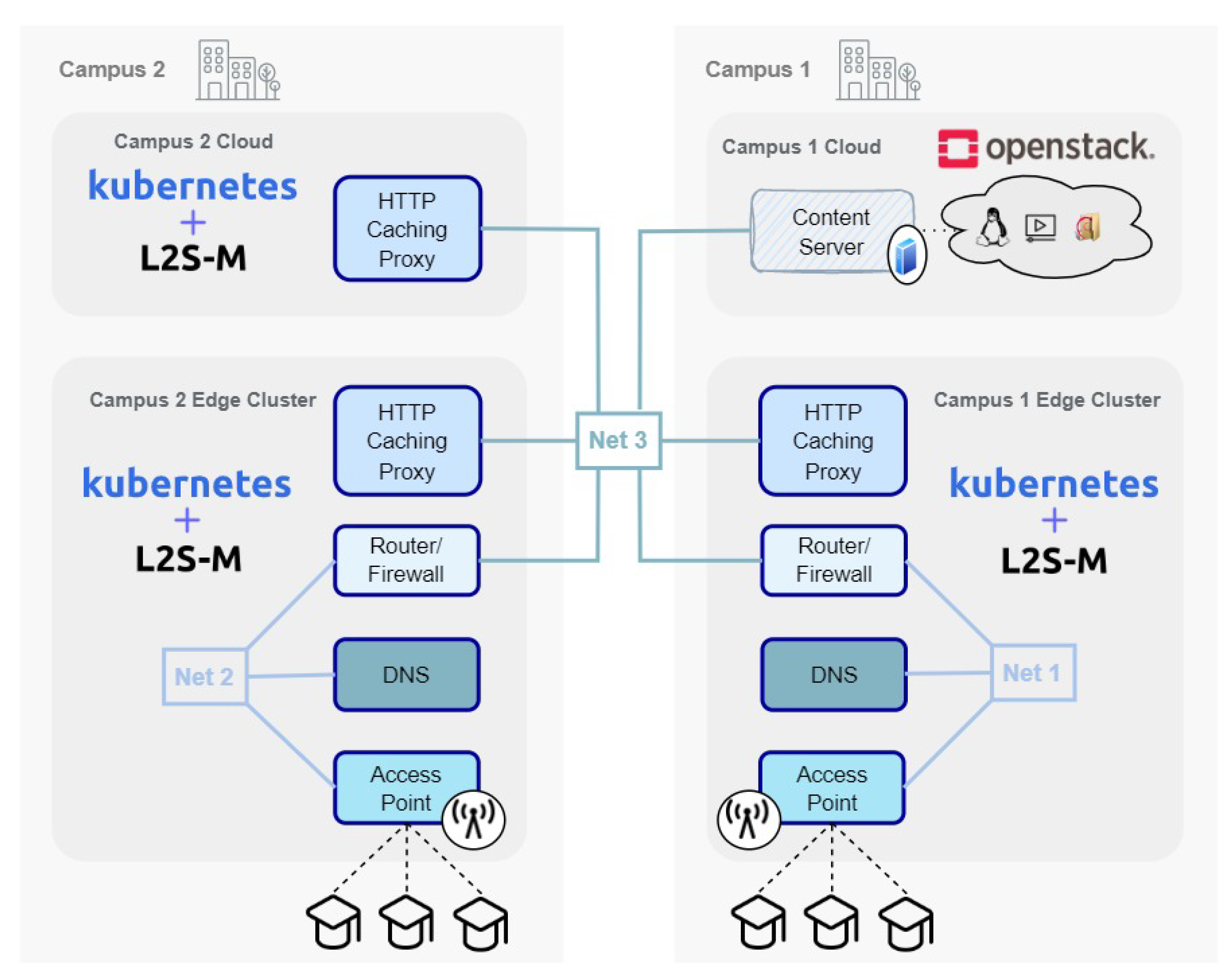
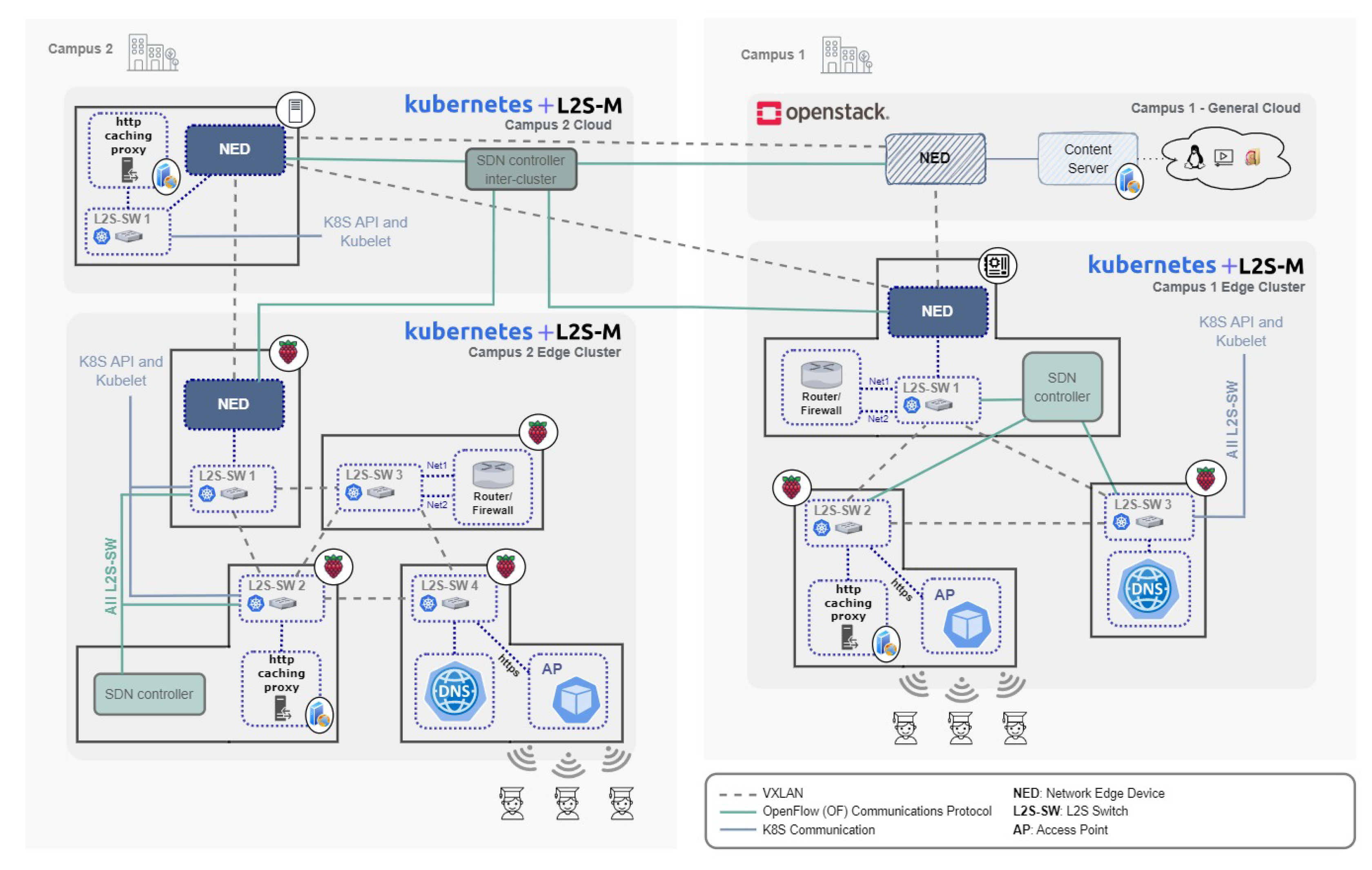
The scenario presented in this paper can be seen in
Figure 8. The first campus in the scenario (on the right) is composed of two different sites: one central campus environment, and one temporary edge site, which is set up only if an event is performed in the university facilities (e.g., a conference or a workshop). The central infrastructure of this campus is regarded as the main cloud of the whole organisation, holding most of the software and teaching resources available to the students and teachers. In consequence, the representation of this site is conducted through two VMs (since these are considered “heavier” machines in terms of available resources). One of the VMs is used as a general-purpose server to host multimedia and software contents. The remaining VM hosts the corresponding NED used to connect this site with the rest of the sites of the university, both the ones in other campuses (inter-campus communications) and the ones in its own campus (intra-campus communications), as long as they are in different sites or clusters. The second site is the edge environment of the campus, and it is meant to represent the temporary devices deployed for an opportunistic event that members of the university will use to retrieve the content, as well as providing a cache server for the university’s CDN. It comprises two Raspberry Pi 4 Model B computers that act as nodes of a K8s cluster where L2S-M is installed. The NED of this site provides the connection of this site with the general cloud, which is the other site in this same campus, and with the other cloud present in the second campus.
The second campus has two different sites as well. The first one is the designated campus’ cloud, which is used as a proxy for the connectivity of the edge environment deployed in the remaining site. This edge environment provides the infrastructure that students will use on a regular basis to download the university content. Naturally, the site offers a proxy as part of the CDN in order to store content in its premises, closing the information to be closer to the students. The NED of the cloud allows for the connection to the two sites in Campus 1 and to the other site in the same campus’ edge. The second edge NED connects this site with the same campus’ cloud. The structure of both edges is symmetrical in our deployment, although each site may have a different infrastructure and configuration, validating the initial premise of the benefits of L2S-M.
The use case that is implemented to validate this research aims to simulate the previously described CDN, where a content server is located in the general cloud, to store all the desired data, one proxy server is located in the edge of the first campus, and two proxy servers are located on the second campus, one on its cloud and one on the edge, all aiming to cache data closer to the user. They will be deployed as different pods running a nginx [
51] web server with the functionality of an HTTP reverse caching proxy. In the cloud of the first campus, the server was installed inside a VM to act as the main content server (i.e., where the information is permanently stored). In order to protect the access to this main cloud from external sources, an HTTP proxy was deployed in the cloud of the neighbouring campus. Regarding the edge sites (present in both campuses), an additional HTTP proxy was deployed to cache the content coming from the remote server. Both edges were designed in a symmetrical way. Apart from the proxy, one access point (AP) was deployed as a pod on each edge, giving the user the possibility to download the content from the CDN by connecting to the proxy available in the edge. To effectively enable this connection, a domain name system (DNS) provides the user with the IP address of the edge HTTP proxy when introducing the URL corresponding to that content. To avoid reaching the HTTP server directly without connecting to the enabled AP service, a firewall service (developed as a Linux router) was introduced in both edges, and it is in charge of forwarding the traffic from the AP into the nginx proxy and vice versa.
For this scenario, some virtual networks must be created to attach the different components, once again in a symmetrical way between campuses 1 and 2, connecting, in the first network, the router and firewall with the DNS and the AP. This can be seen in
Figure 9, where Net1 corresponds to the virtual network in the first campus and Net2 to the one in the second campus. Another virtual network is deployed among the different campuses, connecting the content server with the different proxies and routers. This stands in
Figure 8 as Net3. All these deployments allowed for the connection between elements of the network to be established and for the behaviour of the scenario to be as expected.
5.2. Experimental Environment
Figure 9 showcases the detailed implementation of the scenario, with the different pods that were deployed on each site and the connections between them.
Starting with the first campus, the edge site is represented using a rack of four Raspberry Pi4 Model B computers, all of them having 8 GB of RAM and running an Ubuntu Server 20.04 installation. All these RPis were connected using gigabit Ethernet connectivity (since these are considered fixed devices that could be placed in classrooms all over the campus). All RPis are part of the same K8s cluster, using the L2S-M operator for intra-cluster communications. In order to enable the communications between pods and avoid loops over the L2S overlay created within the cluster, a RYU SDN controller was deployed (running as a pod) using the spanning tree protocol (STP).
Each RPi hosts a different functionality, all of them deployed as K8s pods, which can be seen in more detail in
Figure 9. The first RPi, the closest one to the users, hosts the AP functionality (enabling the requests of content downloads) and the DNS service within the edge cluster. The next hop of the CDN service, once a download has been requested from the AP, is the firewall (implemented as a Linux router) that will redirect the HTTP requests to the proxy, located in the second RPi. This proxy also provides a cache that allows hosting some of the requested content inside the cluster (allowing to have the information closer to the users). The cache can be dynamically modified depending on the demand and the status of the network. If the content is not found in this proxy, it will redirect the request to the proxy located in the campus cloud through the NED present in the remaining RPi, which oversees these inter-cluster communications.
This cloud is composed of a single VM (Ubuntu Cloud 20.04) that hosts a K8s cluster. Two functionalities were deployed (as pods): one proxy HTTP, in charge of redirecting the requests from the edge campus to the main cloud of the university, and the SDN controller used for inter-cluster communication. This last component is essential for the whole functionality of the university since it allows the configuration of all the NEDs present in each cluster/site. Similar to the intra-site communications, this controller was implemented using the RYU SDN controller running a SPT protocol to avoid network loops.
All of the previously described K8s clusters were installed using the 1.26 version of kubeadm [
52], running the K8s 1.26 release. using containerd as the container runtime. For the default networking CNI Plugin, we selected Flannel [
17] since it is one of the most-used CNI plugin solutions in production clusters.
In the case of the main campus, the content server is directly installed and configured in one VM within an OpenStack cluster, and it is connected to the cloud of the second campus and to the other site in the campus premises through a NED, installed inside another VM. Both VMs run an Ubuntu Cloud 20.04 image, using 2 CPUs and 8 GBs of RAM. This content server stores all the multimedia files, Linux images, Debian packages and many other types of files that could be used daily in a university environment. The combination of all the functionalities and elements of both campuses build the CDN service that is implemented in this work.
Due to the nature of the activities that could be present in a university, the edge environment of the main campus is considered a temporary infrastructure that is aggregated into the Smart Campus infrastructure. This new edge site, built as a K8s cluster using L2S-M for intra-cluster communications, has the same functionalities as the edge of the second campus, with the exception that its proxy will directly request the content to the main content server, rather than using an intermediate proxy.
All of the configuration, deployment and network files used in this validation section can be found in the corresponding repository [
53].
5.3. Functional Validation and Results
5.3.1. Throughput Performance
This first set of validation tests aimed at showcasing the possible impact that L2S-M could have in the available throughput for the virtual functions deployed over a K8s cluster. To test this impact, we used the well-known traffic-generation tool iperf3 [
54] in order to test the total available bandwidth between the two pods deployed in the scenario, testing both the standard K8s networking (flannel [
17] for intra-cluster networking, and K8s NodePort for inter-cluster networking) and L2S-M in each scenario. In particular, the pods were deployed using the following configurations:
Two pods deployed in the same node of Campus 2 edge cluster (RPi1).
Two pods deployed in different nodes of Campus 2 edge cluster (RPi1 and RPi3).
Two pods deployed in different clusters (RPi1 of Campus 2 edge cluster and Campus 2 cloud cluster).
For each configuration, an iperf3 flow of 180 s was established between each pod in both directions, using the standard K8s networking and the L2S-M in every iteration of the test. In this regard, each iteration was run 30 times, and then the average of each run was used to calculate the values shown in
Table 1.
As it can be seen in
Table 1, the performance of L2S-M does not introduce any significant performance degradation in comparison with the standard K8s networking approaches (Flannel and service abstraction). L2S-M improves the throughput between the pods when they are co-located in the same node since the traffic generated between them does not need to pass through the Flannel agent deployed in the node, which introduces some performance degradation. For the connectivity between pods that are located inside the K8s cluster, but in different nodes, L2S-M and Flannel exhibit quite similar performance, with a slight throughput decrease in the L2S-M case. Overall, the performance between both solutions is very similar, and showcases that L2S-M does not harm the traffic performance over the K8s cluster.
Regarding the inter-site connectivity scenario, L2S-M provides approximately 50 Mb/s less throughput than its counterpart as expected since K8s services establish the connection directly without the use of IP tunnelling mechanisms, while L2S-M still requires the use of VXLAN tunnels between the infrastructures, which in turn introduces some overhead in the packets exchanged between the pods/VMs. Nevertheless, NodePort communications do not isolate the exchanged traffic between pods, unlike L2S-M, which only distributes traffic to the pods located in the same virtual network.
These tests showcase that L2S-M does not introduce significant performance degradation in comparison with standard CNI plugin communications in K8s.
5.3.2. CDN Download Test
The purpose of this test is to show the capacity of L2S-M to implement complex NSes, like the CDN proposed in this paper, over heterogeneous infrastructures implemented with different management and orchestration solutions.
For this round of tests, we performed the downloading of a fairly large video file (1 GB) from Campus 2 edge and measure the average throughput that the CDN has when a user tries to download some media content in the Smart Campus scenario.
For this test, a pod located in the edge cluster of Campus 2 downloads a video using a specific URL that represents the video content “
https://university-content/edu.mp4”. When the pod tries to download the video content (using the well-known wget program), the DNS service present in the campus edge will translate the URL into the IP address of the local (i.e., campus) nginx server, sending the HTTP request in the process, following the process described in the previous subsection.
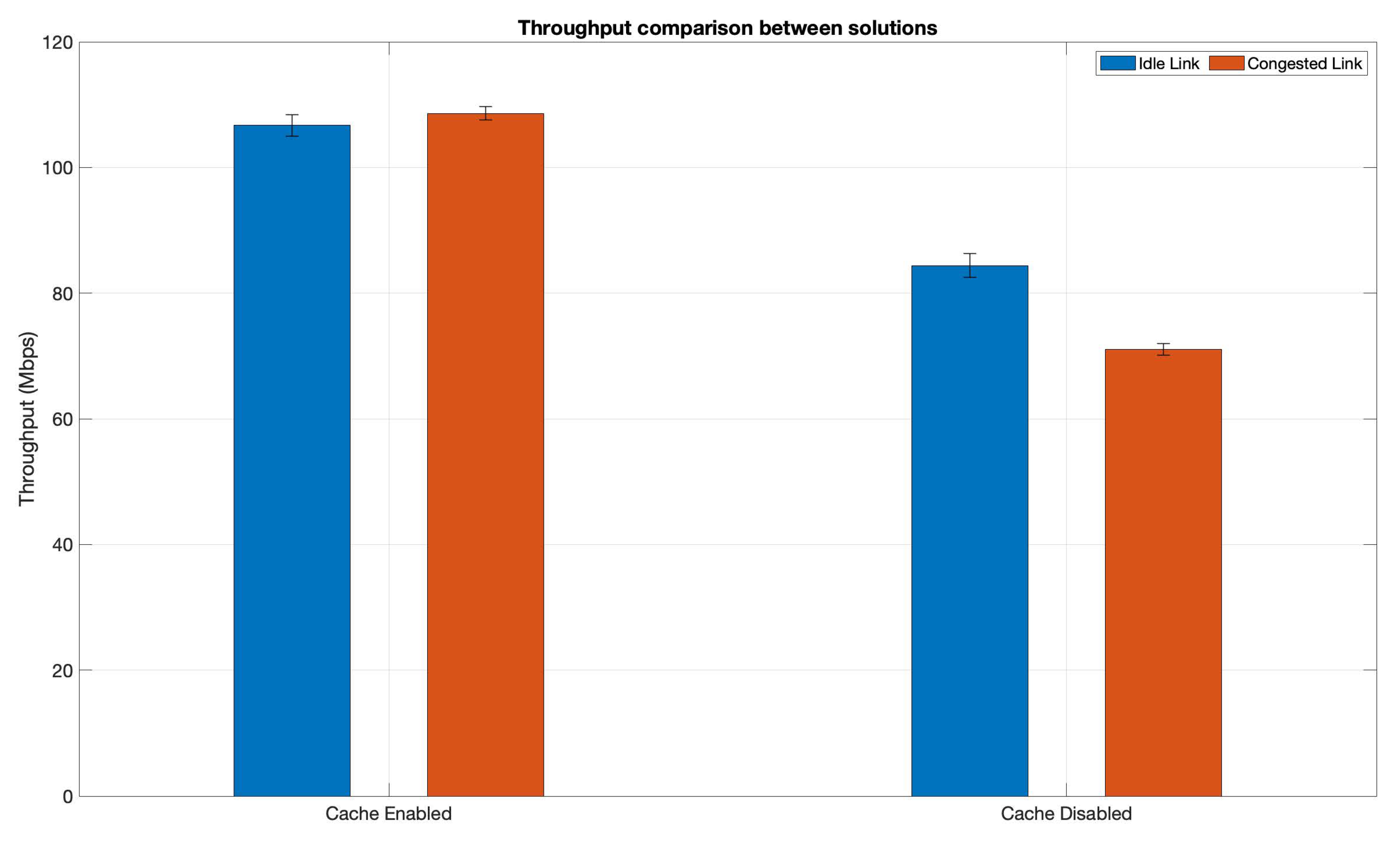
In order to test the efficiency of the CDN in realistic scenarios, these tests emulate the congestion of one of the links used for the download, using iperf3 to send a TCP download at the maximum available rate possible. In this case, the link that is congested during the tests is the one interconnecting both campus clouds since in a realistic scenario it is expected to be the link that exchanges the highest amount of data between campuses.
The cache will be set in two different ways: firstly by disabling the whole cache (making the server a simple http proxy), and secondly, allowing the cache to store the whole video. These modes will clearly showcase the impact of having a cache inside the scenario by reflecting if there is any significant improvement to the available throughput and/or the download speed.
With all these considerations, the performed tests were the following: one set of tests, where the cache in the edge was disabled, performing the download when the link between campuses was idle and then congested. Each set was performed 30 times. Afterwards, the cache was enabled to hosts the whole video, repeating the aforementioned tests (idle and congested links).
Figure 10 showcases the average throughput results, including the 95% confidence intervals.
As it can be seen in the figure, the presence of a cache obviously improves performance in terms of throughput in both scenarios: since the content is closer to the user, it traverses fewer functions and infrastructures, which in turn makes it easier for the nginx to send the content from one site to the other. When the cache is disabled, there is also a significant decrease between the idle and congested scenario. This is the expected behaviour since the content must traverse (and be processed) by an additional nginx server (the one located in the second campus).
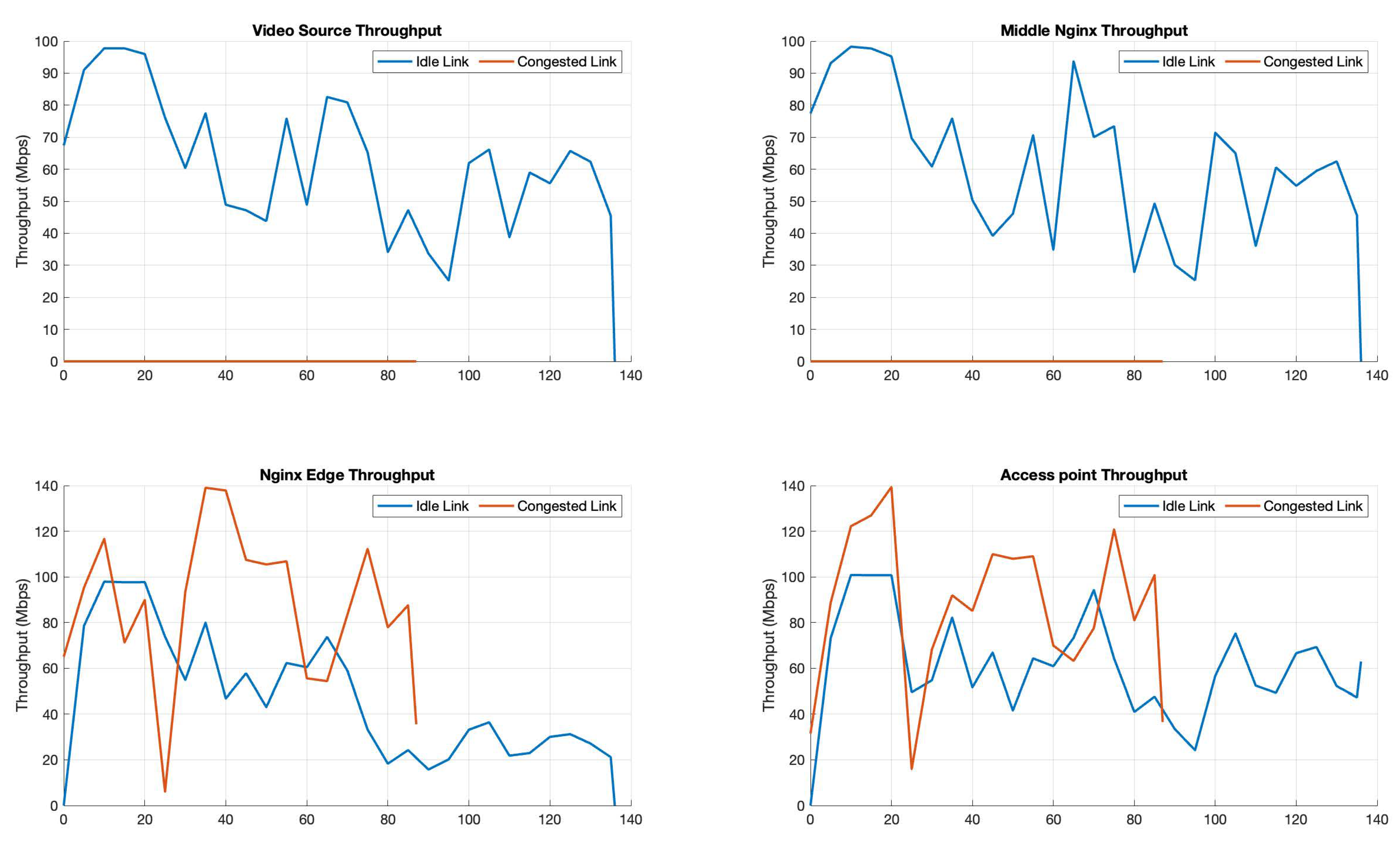
This behaviour can be further seen in
Figure 11, where the traffic on each nginx element can be seen for two runs: one where the cache is disabled, and one where it is enabled (in both cases, the link was not congested). As it can be seen in all figures, traffic is present in all pods/VMs when the cache is disabled since the traffic is generated from the video-source VM in the main campus cloud and traverses the middle nginx pod. Since these entities must process this traffic, the overall throughput is lower, and the download takes significantly more time to finish. On the other hand, when the cache is enabled, the traffic is only generated from the edge nginx in Campus 2, which in turn requires less packet processing in the infrastructure (fewer nginx servers are involved), so the overall bandwidth is higher, and the download is significantly shorter.
5.3.3. Cluster Addition and Wi-Fi Download Test
The last test of this validation section will provide some insights about the capabilities of L2S-M to incorporate a new infrastructure into a complex scenario such as the Smart Campus. It is common that universities hold events with many participants that require access to the Internet or/and retrieve content from the university to perform some activity. Some examples might include congresses, practical/lab sessions, etc. In all these cases, it is important to be able to set up an adequate infrastructure able to effectively host the network services required for each activity. Nevertheless, this set-up must be quick and dynamic since these events frequently change, so the requirements and equipment needed will vary depending on the type of activity being performed.
In this regard, the set-up of a K8s cluster is well known to be simple and fast to deploy (a cluster can be set up in 20 min using administration tools such as Kubeadm [
52]). In a similar fashion, L2S-M (and its inter-cluster functions) can be easily deployed within a K8s cluster as well since its configuration and set-up can be performed in a short period of time (approximately 10 min).
For this test, the Campus 1 edge was deployed using two RPis (which can act as AP) and a Mini-ITx compute node to provide the connectivity with the main university cloud. This last battery of tests uses the RPis Wi-Fi module to provide the channel for the downloads, emulating a real scenario, where other clients would connect into an AP and download the content from there (rather than downloading it in the equipment, unlike in previous tests).
In this case, the audiovisual content was downloaded from an external PC connected into the virtualised AP of an RPI, enabling and disabling the cache to test the CDN functionality. This process was repeated 30 times for every mode, obtaining the download values that can be seen in
Table 2.
As it can be seen in the table, the download speeds are lower than the ones in previous tests. These were due to the use of an unstable medium, such as the Wi-Fi connectivity of the RPis. Nevertheless, both download speeds and average throughput were improved when the cache was enabled in the site, proving again the effectiveness of the CDN.
Beyond the particular results (throughput, etc.) obtained for the different featured scenarios, the main objective accomplished was to show that L2S-M can be used to provide complex network services that might involve different kind of network interfaces like wireless interfaces. This is also a starting point for the exploration of this concept since L2S-M could be used to enable the connectivity with private networks over an infrastructure (e.g., the same way in which VIMs like OpenStack connect to provider networks).
6. Conclusions and Future Work
The rise of new paradigms like NFV in the context of the 5th generation of mobile networks has provided new ways to enable the development and deployment of network services. In this regard, microservice platforms assist in the optimisation and orchestration of network functions in distributed infrastructures. However, these platforms have some limitations due to the flat networking approach that they implement for the communication of their workloads (containers) in order to build a complex application. Furthermore, these solutions can also have some limitations for connectivity with other infrastructures, requiring networking abstractions that could prevent communicating network functions between clusters or other platforms.
To address these issues, this paper has presented L2S-M as a solution that enables link-layer connectivity as a service in cloud-native ecosystems. L2S-M provides a programmable data plane that microservice platforms (like K8s) can use to create virtual networks that can be used by the containers to communicate at the link-layer level, since they will see the rest of the containers as if they were located in the same local area network (even though they might be distributed in different locations, depending on the cluster and the underlying infrastructure). Using these virtual networks, L2S-M provides the necessary network isolation required to deploy network and vertical specific functions in microservice platforms, which current solutions cannot easily provide. Furthermore, since L2S-M uses SDN technology to establish the paths between pods in a cluster, other SDN applications can be flexibly deployed to support traffic engineering and optimise traffic distribution, using an alternative network path across the L2S-M overlay.
This paper also provides a first exploration of the potential of L2S-M to provide inter-cluster communications between containers using virtual networks, enabling the direct communication of network functions between heterogeneous infrastructures managed by different platforms, which can implement different virtualisation techniques, or even run bare-metal functions.
This paper also presented the use implementation of L2S-M in a complex Smart Campus scenario, deploying a CDN to distribute multimedia content in a complex, distributed and heterogeneous scenario. The tests performed in the validation of this paper showed that L2S-M is suitable to deploy complex NSes based in microservices that require the use of multiple isolated virtual networks for their proper functionality, interconnecting workloads located in different infrastructures over geographically distributed locations. Moreover, these tests depicted the flexibility of L2S-M to incorporate new infrastructures, like Wi-FI access points, to extend the functionality of the NSes in the use cases.
Our future work for the advancement and further development of L2S-M includes the implementation of the overlay manager figure in the solution to dynamically modify the overlay network. Furthermore, we will also explore the implementation of L2S-M with SR-IOV interfaces to enable its direct use with the physical switching equipment commonly present in data centre infrastructures. This future work will also involve the exploration of alternative SDN controllers to increase the functionality and isolation aspects of L2S-M, as well as the development and application of SDN algorithms to apply traffic engineering mechanisms. Finally, we want to contribute to the relevant open-source communities with L2S-M. In this regard, we are working on a feature in OSM to support the creation of virtual networks in K8s clusters, using L2S-M as the reference operator [
49].


