Article

An Efficient Model-Based Clustering via Joint Multiple Sink Placement for WSNs

by
Soukaina Bouarourou
1,*,
Abderrahim Zannou
2,
El Habib Nfaoui
1 and
Abdelhak Boulaalam
3
1
LISAC Laboratory, Faculty of Sciences Dhar EL Mahraz, Sidi Mohamed Ben Abdellah University, Fez 30000, Morocco
2
ERCI2A, Faculty of Science and Technology Al Hoceima, Abdelmalek Essaadi University, Tetouan 93000, Morocco
3
LISA Laboratory, National School of Applied Sciences, Sidi Mohamed Ben Abdellah University, Fez 30000, Morocco
*
Author to whom correspondence should be addressed.
Future Internet 2023, 15(2), 75; https://doi.org/10.3390/fi15020075
Submission received: 10 January 2023 / Revised: 1 February 2023 / Accepted: 4 February 2023 / Published: 15 February 2023
(This article belongs to the Section Internet of Things)

Abstract

:
Wireless sensor networks consist of many restrictive sensor nodes with limited abilities, including limited power, low bandwidth and battery, small storage space, and limited computational capacity. Sensor nodes produce massive amounts of data that are then collected and transferred to the sink via single or multihop pathways. Since the nodes’ abilities are limited, ineffective data transmission across the nodes makes the network unstable due to the rising data transmission delay and the high consumption of energy. Furthermore, sink location and sensor-to-sink routing significantly impact network performance. Although there are suggested solutions for this challenge, they suffer from low-lifetime networks, high energy consumption, and data transmission delay. Based on these constrained capacities, clustering is a promising technique for reducing the energy use of wireless sensor networks, thus improving their performance. This paper models the problem of multiple sink deployment and sensor-to-sink routing using the clustering technique to extend the lifetime of wireless sensor networks. The proposed model determines the sink placements and the most effective way to transmit data from sensor nodes to the sink. First, we propose an improved ant clustering algorithm to group nodes, and we select the cluster head based on the chance of picking factor. Second, we assign nodes to sinks that are designated as data collectors. Third, we provide optimal paths for nodes to relay the data to the sink by maximizing the network’s lifetime and improving data flow. The results of simulation on a real network dataset demonstrate that our proposal outperforms the existing state-of-the-art approaches in terms of energy consumption, network lifetime, data transmission delay, and scalability.

1. Introduction

Wireless sensor networks (WSNs) have notably increased in popularity over the last few decades. Their success, and the rising demand for them, are reflected in the ever-expanding range of applications in various fields, such as transportation [1,2,3,4,5], health [6,7,8] (human activities in health care), manufacturing [9,10,11,12], military [13,14] (battleground surveillance by the military), and environment [15,16,17] (wildfire early detection, air pollution monitoring, and water monitoring). WSNs are also critical components of the Internet of Things (IoT) [18].
A typical WSN consists of several sensor nodes (SNs) and at least one base station (BS), called the sink. An SN is a small device with limited abilities (energy, processing capacity, and memory) that is placed in the environment to sense and gather the necessary data before sending it directly (single hop) or via other multihop communications to the nearest sink [19]. The sink is in charge of receiving and conveying these gathered data to the final user and is outfitted with high energy and processing capabilities [20]. Communications consume more than 70% of the battery energy among various nodes. In sparse topology, a WSN with limited node capacities cannot function as intended if one of the network’s sensors runs out of energy [21]. In dense topology, the overlapped sensing areas significantly increase unnecessary energy consumption and shorten the network’s lifetime. For that reason, it is necessary to construct an energy-efficient WSN to maximize the network’s lifetime.
The lifetime is the time until the energy of the first sensor node is exhausted [22], and to improve it the flow balance between nodes must be significantly improved. SNs closer to the base station conserve a considerable quantity of energy for extended periods of time, and energy consumption is related exponentially to distance during data transmission. Hence, the distance between communicating nodes determines the quantity of energy used for data transmission. Specifically, the nodes nearest to the sink consume less energy. In contrast, distant nodes may use other nodes to transmit the data to the sink, which causes energy depletion of the SNs that are closest to the base station. Indeed, the sink location impacts the network’s lifetime based on its distance from a significant number of sensor nodes.
An excellent way to design an energy-efficient WSN is to deploy numerous sinks rather than a single sink [23]. When designing a network with several sinks, we intend to determine how many sinks there should be. However, even more crucially, we need to determine where the sinks should be placed and then select the optimal path for data transmission. Clustering is a promising strategy for managing the WSN structure, since it has the potential to improve network performance. It aims to group nodes based on predetermined criteria, such as ensuring the quality of service, balancing the network load, and optimizing the resource requirements [24]. Resource-constrained nodes no longer need to send data directly to sinks using clustering techniques. Other approaches are proposed to outperform energy efficiency, such as sleeping mechanisms [25], data aggregation algorithms [20] and compressed sensing mechanisms [26]. The sleeping mechanism significantly reduces energy consumption by putting sensors to sleep or waking them up. The data aggregation algorithm is mainly used to process massive data that does not supply meaningful information to its owner in its current inconsistent form. The compressed sensing mechanism takes advantage of the redundancy present in environmental WSN signals to decrease the number of transmitted measurements and, as a result, achieve an appealing reduction in network energy consumption. However, it necessitates significant data preprocessing, which runs counter to Ambient Intelligence domains’ processing and energy limitations.
In general, sensor nodes can be deployed in different environments with different technologies, such as Wireless Body Sensor Networks [27] that gather and evaluate patients’ vital-sign-related data by deploying various bio-medical sensors (body temperature, blood pressure, heartbeat, etc.) in the human body for an extended period, thereby lowering healthcare costs. An essential part of the Intelligent Transport System (ITS), the Vehicular Ad-hoc Network (VANET) [28], connects and allows wireless communication between moving vehicles. It is a particular type of Mobile Ad-hoc Network (MANET). The Flying Ad-hoc Network (FANET) [29] consists of several Unmanned Aerial Vehicle (UAV) nodes that connect wirelessly. UAVs can be controlled remotely or using pre-programmed instructions.
Typically, SNs consume a larger amount of energy while transmitting data. Hence, reducing the amount of redundant data transferred to the BS is crucial when the cluster head (CH) nodes in a network are appropriately selected. Additionally, it is essential to examine the routing protocol in the main features and common scenarios to ensure real-world WSN construction and optimum environment simulation for further improvements using a range of optimization methodologies [30].
Previous studies have notably discussed approaches to sensor deployment, sink placement, and data transmission for energy efficiency. These techniques [23,31,32,33,34] are not suggested in the case of large-scale sensor deployment. Other studies focused only on the issue of routing paths without attaching them to sink placements [31,34,35,36,37,38,39] or addressed only the sink placement [23,32]. Studies have provided a clustering model for data routing, but there are considerable shortcomings in the clustering methods. In particular, they put a tremendous load on CH and ignore the residual energy and distance between the Cluster Head and the sink, which impacts energy consumption. Therefore, we need a solution that addresses the aforementioned issues in order to reduce energy consumption, increase the network’s lifetime, and shorten the data transmission delay in a constrained IoT network. Thus, we have to propose a fully analytical model that considers the most common review limitations: clustering optimization, placement of multiple sinks, and data routing problems in heterogeneous WSNs.
In this research, inspired by swarm intelligence methods, especially the ant clustering algorithm, we propose an efficient model based on clustering that determines the ideal position for multiple sinks and routing data pathways in WSNs. The following are some of our research’s significant points in terms of the proposed model-based clustering:
  • We propose a complete model that aims at increasing the network’s lifetime. It performs essential tasks like CH selection (higher Cp factor), path construction from sink to CH (less costly path), and sink placement (in the barycenter of the cluster); as a result, it minimizes the load on the sensor nodes.
  • Under the operation of our model, no intermediate node participates or transmits their data packets with less than an energy threshold and more than a distance threshold (long link—discussed in Section 3.1), thereby conserving a significant amount of energy.
  • We compared our proposed technique with others under various simulation settings (varying the number of sensor nodes, CHs, and sinks) to identify areas of limitation and found that it outperformed all of them. We observed that the number of hops is reduced by more than 4% to one hop, and the residual energy is increased by more than 3%.
We have adopted the ant clustering algorithm because of its various features [40]: (i) it requires minimal information about the issue at hand; (ii) it can typically complete both broad and parallel searches over the area of potential solutions by having a swarm (population) of candidate solutions. In our study, the execution time is a carried-out concern, so a parallel search is needed; (iii) it is scalable in clustering issues because of its distributed nature [41]. In this research, we address the problem of clustering in a constrained environment in which we have a high number of varied sensors and features; (iv) it is robust to the impacts of outlier data [42,43,44,45]; (v) it examines the space issue more deeply than greedy algorithms that use local search. According to [46], ant-based algorithms can find near-optimal solutions.
The structure of this work is organized as follows: the second section includes a summary and a review of the most recent works on sink placement and data routing paths. In Section 3, we provide a definition of the problem, the ant clustering algorithm, and the adopted model of energy. In Section 4, we present an appropriate way to formulate the proposed method, which deals with four issues: deployment sensors, applied clustering, multiple sinks placements, and data routing paths. In Section 5, we further discuss the main extracted results. Finally, a thorough conclusion and proposal for future work are presented in Section 6.

2. Related Works

The optimization of energy consumption and the maximization of a network’s lifetime are related to different factors such as data routing, sink assignment, and optimal multiple sink locations (i.e. finding the optimal number and the best placement of the sinks).

2.1. Sink Placement

Single-sink solutions are not highly efficient in applications requiring large-scale deployment, such as environmental monitoring, industrial networks, surveillance, and agricultural scenarios.
In an early study by [23], the authors used an iterative clustering technique with multiple sinks in the agricultural field to find the optimal location for each sink while maximizing the network’s lifetime. To ensure the network’s scalability, they used the k-means method to divide the whole network into clusters, where each sink is situated in the middle of each cluster in terms of energy. The number of sinks increases until a necessary lifetime is reached. However, due to the vast number of SNs and the deterministic static number of sinks at constant positions in the network, the technique is unsuited to large-scale networks. In addition, the route from sensors to sinks needs to be considered.
Another work [47] modelled the problem of optimal sink position and sensor-to-sink communication as a mixed integer linear programming (MILP) model that attempts to prolong the network’s lifetime and simplify the routing to the sink to gather data using the PSO algorithm. The model indeed prolonged the network’s lifetime, but it may choose the longest path. An analytical model [32] proposed to deal with the energy hole issue by allocating k-sinks in the network based on the k-median problem, hence marking a more extended network lifetime. However, the model did not mention the type of applications used, since in cognitive WSN the sinks are not qualified for processing the data of every sensor.
Other studies [48] combined sink position, sensor position, scheduling, and routing with the linked coverage (SPSRC) model in a single model that deals with the design problems mentioned. The SPSRC model allows the deployment of sink and sensor locations, as well as scheduling/monitoring the activity of the located sensors, and the data travels from each energized node to its associated sink for network coverage across a restricted zone area. Meanwhile, ref. [49] introduced a model for heterogeneous-WSN using a clustering technique founded on the energy forecast (CTEF). This model considered quality and packet loss rate to decrease SN’s energy consumption. Unfortunately, coverage time has not been considered in this model. As a result, it impacts the lifetime performance of sensor networks.
The use of a mobile sink trajectory, where the moving sink traverses all SNs and gathers data by means of single-hop communication based on the Hilbert curve, was initiated in [35]. However, this method suffers from a high transmission time, since data is only conveyed to the sink by traveling near to the boundary and in a single hop. Similarly, efficiency, scalability, and availability are factors to be achieved with a single sink. The authors of [50] gathered sensor data using several sinks around the observation field. The sensors have three-sector antennas and send data to BS directly or via intermediary nodes, depending on which sector they use.
In [51], they developed mixed-integer linear programming (MILP), in addition to referencing the hot-spot or energy-hole problem by proposing the utilization of “optimal mobility patterns” on three representations for multiple sinks (random, grid, and spiral patterns). As a result, it extended the WSN lifetime as long as possible. A mobile sink can be suggested as a solution to the energy hole problem, but it remains challenging to design a dynamic path sink.
Some research [52] has combined the moth flame optimization (MFO) algorithm and differential evolution (DE) algorithm to construct an optimal mobile sink route by clustering the wireless sensor networks. This technique reduced energy usage and maximized the network’s lifetime. Nevertheless, it failed to calculate the data transmission delay and throughput. Table 1 summarizes relevant research papers studying sink placement.

2.2. Data Transmission and Routing Paths

The crucial role of each sensor in a WSN is to regularly transfer its perceived data to the sink. The simple method is Direct Transmission (DT) [34], a scheme where sensors transmit directly to the sink nodes without using an intermediate node. This configuration is mainly employed in networks with topologies that rely on a central node to oversee the operation. However, it results in an unequal depletion of energy among the nodes. As a result, nodes located far away from the sink are depleted more rapidly than nodes placed near to the sink.
The significant variance in node energy consumption shortens the total network lifetime, breaching fundamental WSN requirements (energy efficiency). Several methods have been offered to address these concerns, including minimizing the energy consumption of SNs and enhancing their lifetime. The routing solutions may be classified into flat and hierarchical protocols. Flat routing protocols [53], such as DD [54] and SPIN [55], use data diffusion to load the network with a massive number of packets, which impacts transmission time and the network’s lifetime. Flooding is the most fundamental adaptive strategy for WSNs. It is highly dependable since it ensures network throughput across the sink’s many little paths. However, it suffers from traffic implosion, overlapping, and resource blindness [56].
Clustering techniques are used in hierarchical routing to improve network performance. Clusters of nodes are formed, with each cluster having its own head node. The Cluster Head nodes are in charge of gathering and aggregating data from the particular clusters and relaying the aggregated data to the sink node. Low energy adaptive clustering hierarchy (LEACH) [57], power-efficient gathering in sensor information systems (PEGASIS) [36], centralized energy efficient distance (CEED) [31], threshold-sensitive energy efficient sensor network protocol (TEEN) [58] and general self-organized tree-based energy-balance (GSTEB) [37] are some of the most well-known hierarchical routing systems.
One of the first studies on this issue was in relation to the LEACH system. In this system, the CH receives data from the other members’ nodes in the cluster, collects it, and then sends it all to a base station. LEACH rotates the CH to ensure that energy usage is evenly distributed. The dynamic and distributed clustering protocol LEACH is the most outstanding example. LEACH increases the network lifetime by eight times more than DT. Nonetheless, it assumes that the medium is static.
In another way, several solutions to improve network lifetime using the Compressive Sensing (CS) theory have been proposed by researchers. Cluster-based routing, CS theory and single-sink deployment are all discussed in [59]. The researchers evaluated the influence of BS location on transmission numbers and offered two data gathering approaches: Energy-aware CS-based Data Aggregation and Energy-balanced High level Data aggregation Tree (EHDT).
The distance between nodes and the associated sink is a critical factor in choosing the best path to transmit the collected data in an energy-efficient routing technique [38]. This low-energy routing path should in fact reduce communication costs. Using block-diagonal matrices as measurement matrices, ref. [60] combined CDG and clustering in WSNs, resulting in a significant decrease in transmission power utilization. These cluster-based CDG methods, however, still necessitate a substantial amount of intra-cluster data exchanges. Furthermore, none of the previous studies have looked into the robustness of signal recovery performance in the event of network node drops.
The authors of [33] presented two algorithms: Multi-sink Placement and Anycast Routing (MPAR), and Extended Multi-sink Placement and Anycast Routing (EMPAR). The two algorithms are built for a two-level architecture, with nodes grouped on the first level. A load-balanced data aggregation routing tree connects SNs to the corresponding CH. At the second level, the algorithms optimized the sojourn positions of mobile BSs using a particle swarm optimization technique. Each mobile BS’s ant colony optimization technique represents the high-level Anycast routing tree. The data is then sent from CHs to BSs using a hybrid compressive sensing approach. Nevertheless, as the number of nodes grows, the runtime complexity grows. The network becomes expensive when using several sinks. In this regard, succeeding in choosing their best possible location is increasingly challenging as the number of sinks increases.
By dividing the network into balanced clusters, the Hybrid Energy-Efficient Multi-Path (HEEMP) routing algorithm improves the energy efficiency of WSN networks [39]. It also solves the issue of imbalanced cluster formation. In order to reduce the energy used during data transmission from the SNs to respective CHs, HEEMP has employed a multi-hop communication technique inside the cluster.
Recently, a technique [61] was proposed based on the DP clustering algorithm that allows nodes to be grouped based on their coordinate locations. It also enables SNs to self-generate decisions depending on the data flow condition in the network and builds an automated path plan that extends the network’s lifetime. Although the study improves the lifetime, choosing a low-energy node as a CH results in a non-uniform distribution of CHs. Table 2 shows the most recent studies on routing protocol and sink placements.

3. Preliminaries

This section provides background information, including the definition of the problem, the ant clustering algorithm, and the energy model adopted for the rest of this paper.

3.1. Problem Definition

A typical WSN consists of N+M nodes, where N sensor and actuator nodes are deployed randomly in an area with different communication ranges and M stationary sinks. Sensor nodes can monitor environmental factors as well as generate data. Actuator nodes or end-users can use the generated data. The actuator nodes can convey data from SNs via intermediary nodes or end-users to the BS in order to execute a physical parameter. In general, each node can transfer data to the sink in direct or indirect communication. Therefore, the WSN serves as a link between the physical and digital information worlds by gathering data from its surroundings and transmitting it to digital devices like computers.
Direct communication is the process of allowing nodes to communicate directly with the sink. It would only be accessible to nodes with a communication range more extensive than their distance from the sink (within range of the sink). Indirect communication is available for all nodes. It is based on assigning intermediate nodes to convey data to a sink.
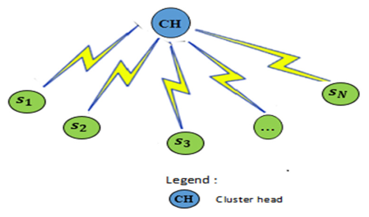
Furthermore, indirect communication can be visualized in two cases. Firstly, the node’s packets are usually sent to neighbour nodes based on their communication range (within range of neighbouring nodes) until they reach the sink. Thus, the nearest node to the sink will receive different requests, which causes it to deplete its energy faster (hole energy issue), as shown in Figure 1. In the simplest scenario, each node sends packets to the neighbouring nodes, which may be along the longest path. Consequently, this kind of scenario can eventually cause many nodes to run out of energy. In the second case, the nodes are grouped into clusters, and each specified CH node transmits data from its cluster members to the sink; this reduces their energy consumption but has a heavy toll on CHs.
Figure 2 illustrates this scenario. Furthermore, all nodes have to relate to a single CH by communicating outside the conventional radio range. As a result of the formal scheme, service quality and performance suffer a severe degradation. For this purpose, the nodes are either clustered physically or virtually, which enables a comprehensive visualisation of the study environment and better control of environmental variables. Moreover, a specific node is designated as the Cluster Head based on a selection factor, in addition to placing a sink in the cluster’s centre, which aims to minimize energy consumption and lengthen the network’s lifetime.
The network is depicted as a graph G (S, A), where S = {n1,n2, ...,nN+M} nodes, and A represents wireless connections. Table 3 describes the notations used in the remainder of this paper.

3.2. Ant Clustering Algorithm

This sub-section provides a general summary of the ant clustering algorithm; later we will propose an improved version for the WSN context. The ant clustering algorithm was introduced by [62], and it is a swarm-intelligent approach for clustering issues inspired by the ant-like behaviour exhibited [63]. The algorithm is based on the foraging behaviour of real ants hunting for food. The method uses the ants to deposit an amount of pheromone that reflects the problem to be grouped during their movements. Hence, an ant is placed at each data point site, and the ants are free to move about the search space in order to identify locations with high pheromone density. The quantity of pheromone deposited at various locations across the search space controls the movements of the ant. The introduction of a pheromone function to the grid enhances the reward for dropping objects in more dense areas of the grid. Therefore, the more pheromone is deposited, the more ants congregate. This results in the formation of homogeneous clusters of data.
The grid size is proportional to the number of objects. The agent ants are free to travel around the grid, picking up or discarding objects based on their resemblance to other objects, and the density of the objects in their current local area, as well as the status of the agent ant (whether it is loaded or not). Low-density neighbourhoods (low amounts of pheromones) increase the likelihood of an ant picking up an object, but a remarkable resemblance between things in the neighbourhood area (high amount of pheromone) decreases it. On the other hand, high-density communities increase the chances of dropping an object. The grid’s agent ants and objects can be in one of two states: (a) the agent ant is holding an object i and calculating the dropping probability at its current location; (b) another agent ant is unloading and calculating the probability of picking up an object. Finally, the agent ants aggregate the objects on the grid into heaps containing objects similar to one another.
The density distribution function for an object i, at a specific grid position d, is given by the Equation:
f ( i ) = 1 S 2 j 1 d i , j α   if   f i > 0   0   otherwise
where S 2 is the number of cells in a general neighbourhood area, d i , j is the distance between i and j, which is commonly based on Euclidean distance, and α is a constant that describes the scale for dissimilarity among objects. Once similar or equivalent things hold all the sites nearby, the f i may achieve its maximum value. The picking up and dropping probability of an object is given by of Equations (2) and (3), respectively.
P pick i = ( K 1 K 1 + f S i   ) 2
P drop i = ( f S i   K 2 + f S i   ) 2
where, K1 and K2 are two constants.

3.3. Energy Model

The energy consumption of constrained nodes is a crucial criterion for evaluating IoT solutions. During the design and operation of the proposed approach, a radio model is utilized to study the parametric effect. In this approach, a sensor node consists of seven parts: transmission and reception electrical equipment; transmission and reception antennas; transmission amplifiers; and data processors. Energy is consumed according to the number of operations of data transmission, data reception, and data compression. We assumed the energy model from [15]. Their version incorporates free space and multi-path fading channels relying on source and destination distances. In radio and amplifier electronics, the transmission phase consumes energy as follows:
E T b , D = b × E Elec + b × E D × D 2 if   D < D threshold b × E Elec + b × E mp × D 4 if   D D threshold
where b is the number of bits (data) sent across a given distance D, E Elec is the entire amount of electrical energy required to send or receive one bit of data using modulators, digital coding, and other electronic circuits, E D is the amount of power required by the amplifier to send data to the receiver directly, E mp is the amount of energy required by the amplifier to convey data through multiple nodes in a multi-hop network, and D threshold is the threshold distance, which is calculated as follows:
D threshold = E D E mp
The receiving phase consumes the following to receive data:
E R b , D = b × E Electrical

4. Our Proposal

This research proposes a new strategy for placing multiple sinks in the best positions, and for transmitting and conveying data through an optimal short path that minimizes energy consumption, maximizes the network’s lifetime, and reduces data transmission delay.

4.1. Deployment Sensors

In our model, we assumed that N nodes are spread randomly throughout the environment and that each node i has a unique identity (ID). S(i) is the set of node i’s neighbours. Each node i can adopt one of the two types of communication: single-hop, in which a node near the sink sends its data directly as a direct node, and multihop, in which a distant node uses intermediate nodes to send its data to the sink. Below are the assumptions made in our model:
Assumptions:
  • Sensor nodes are stationary and are deployed randomly in the environment.
  • Multiple sinks (base stations) should be in fixed positions.
  • The sensor nodes in the base station’s communication range transmit data directly to the sink.
  • The sensor nodes are aware of their neighbours’ node locations.
  • The sensor nodes can send and receive data from nodes in the communication range.
  • Each sensor node’s total energy consumption cannot exceed its initial energy.
  • All sensor nodes have different energies, communications, and sensing ranges.

4.2. Improving the Ant Clustering Algorithm for Sensor Node Clustering

To improve and facilitate communication between each node and the sink utilizing an optimal path, we offer a metaheuristic strategy for forming clusters via the CH. The CH are determined by the SNs with the highest chance of picking factor. Finally, clusters are formed by the improved ant-clustering algorithm (IAC). Some nodes use a multihop routing mechanism inside clusters to interact with the cluster head, and once all of the cluster members receive data packets, the data along the precomputed path are transferred to the sink.
Our approach improves the ant clustering algorithm by adding three elements that increase the quality and speed of clustering. Algorithms 1 and 2 depict the suggested IAC algorithm in two steps: initialization and main clustering steps, respectively. In the initialization step, clustering is performed based on the communication range and the distance between each sensor and the most similar cluster head. At the end of this step, we obtain k clusters and other nodes (outliers) that are not yet assigned to any cluster. The main clustering step continues to formulate clusters by using the pick-up and dropping probabilities and the ant’s short memory to ameliorate the clusters’ formation and assign each outlier node to the most similar cluster head. Therefore, this memory is checked upon selecting a new sensor (including the outlier node) to determine the ant’s movement bias. Accordingly, the ant tends to move towards the site of the last similar cluster head it visited. We assume that each sensor can remember the CH relaying to the cluster and the number of clusters (CN) in which it is situated. The CN and CH are established in the initialization step, and the CN is later updated during the main clustering procedure, as described below.

4.2.1. Initialization Step

Firstly, sensors are randomly deployed on a grid with a maximum of one sensor allowed in each cell. In our solution, the grid is represented by a two-dimensional array, where each element contains a number of sensors. Furthermore, empty cells can be assigned to the corresponding element in the array with a predefined value (such as 0). Sparse matrices are effectively utilized to represent the two-dimensional array when the size of the grid is very large. Next, we calculate the chance of picking a cluster head node for each node and then choose k cluster heads using Equation (7), which is defined as follows:
Cp i = ( R energy   ( S i ) max _ R energy   ) × ( C range i max _ C range )
where Cpi is the chance of picking cluster head node i, and R energy   S i and C range i are the residual energy and communication range of S i , respectively. max _ R energy and max _ C range are the maximum values of the residual energy and the network’s maximum communication range, respectively.
We determine the optimum number of clusters, k, using one of the widely-used performance measures in cluster analysis, the Silhouette index (SI) [64]. A higher SI value indicates that data points are less similar to other clusters and more similar to their own cluster. The Silhouette index used in distributed clustering is determined as follows:
SI K = 1 NK k = 1 K n = 1 N SI S i
SI S i = b S i a ( S i ) max ( a S i , b S i )
where K is the number of clusters in each experiment, a ( S i ) is the average dissimilarity of the i th object to all objects in the same cluster, and b S i is the average dissimilarity of the i th object with all objects in the closest cluster.
Algorithm 1: Initialization phase (IAC)
1. 
For each sensor node S i  do
2. 
         Calculate Cp i factor using Equation (7)
3. 
End for
4. 
Sort all the SNs in descending order based on Cp
5. 
Select the k first SNs that have a maximum value of Cp as CH using Equation (8)
6. 
CHs = j = 1 k CH j
7. 
S T   = S T     CHs
8. 
for each S i in S T  do
9. 
         for each CH j in CHs do
10. 
               Calculate d ( S i   , CH j ) using Equation (10)
11. 
       End for
12. 
       Select min_d( ( S i   , CH j )
13. 
       if  C range ( S i   , CH j ) ≥ min_d( ( S i   , CH j ) then
14. 
                         Put S i   near CH j
15. 
                         S i   . CN ,   CH j . CN
16. 
       else                     //     C range S i , CH j < min Futureinternet 15 00075 i001 _ d ( S i   ,   CH j )  
17. 
                         Drop S i in a free cell in the grid
18. 
                          S i   . CN     CH j . CN
19. 
//NewNumber = total number of clusters + 1
20. 
       End if
21. 
End for
Initialized clusters with a most similar cluster head (MSCH) are formulated by selecting the minimal distance min_ d S i   ,   CH j between each sensor node S i and each cluster head CH j . Each node’s property is represented by the Euclidean distance of the sensors, which is defined as follows:
d ( S i   ,   CH j ) = ( L = 1 N att ( S i   . att L CH j . att L ) 2
where d S i   ,   CH j is the distance between the sensor S i and the CH j , S i   . att L is the L th attribute of sensor S i , and CH j . att L is the L th attribute of the j th Cluster Head.
Node S i with a distance to CH j less than their communication range C range ( S i ,   CH j ) is assigned to the cluster via   CH j . The CN of S i is changed to CH j ’s CN. Alternatively, the S i that failed to be assigned to any cluster is placed in a random free grid cell, and S i CN is updated. The main clustering step then begins after the initialization process.

4.2.2. Main Clustering

Once the previous phase is complete, we will have obtained k clusters with their CHs and other nodes that were not yet assigned to any clusters (free clusters). We apply Algorithm 2. The ant moves randomly around the grid, calculating the dropping probability function for empty cells along the way after verifying the pick-up probability. If a sensor’s drop probability in an empty cell exists, the ant will drop it, and the CN of S i will be replaced by the CN of the closest CH in the ant’s neighbourhood while verifying the communication range. Otherwise, the ant will randomly place S i in a grid cell (without changing the CN of S i ), which is considered a cluster.
Algorithm 2: main clustering (IAC)
1./*Main loop*/
2.for t = 1 to t max  do
3.      for all ants do
4.             If (ant unladen) then
5.             Compute P pick ( S i   ) using Equation (13)
6.             Select a random real number P r ͼ [0,1]
7.                  If ( P r P pick S i   )  then
8.                    Pick up S i  
9.                 End if
10.              Else
11.                     If (ant carrying object) S i   ) then
12.                        Find MSCH
13.                        Compute P drop ( S i   ) using Equation (14)
14.                        If ( P r P drop S i   )  then
15.                             Try to drop S i   near MSCH
16.                              S i   .CN ← MSCH .CN
17.                             refreshed_memory(ant)
18.                        end if
19.                    End if
20.                     if UnsuccessfulTries > δ then //δ is a predefined threshold
21.                       α ← α + ∆α
22.                      end if
23.             end for
24.  end for
In addition, as mentioned below, we applied several modifications to the ant clustering algorithm to boost its performance. We used short-term memory for each ant to improve the speed and the quality of clustering [23]. As a result, each ant can remembering a few sites where it has effectively dropped a sensor. Then, upon selecting a new sensor, this memory is checked to bias the ant’s direction movement. Eventually, the ant returns to the location where it last dropped a comparable sensor.
During the pick-up/dropping function, the extent of similarity between sensor S i and its neighbours is calculated as follows (we have changed the fundamental notion of this formula offered by [23] with our clustering problem):
f ( S i   ) = max ( 0 ; 1 S 2 S j   S i [ 1 d ( S i   ,   S j ) × C range ( S i   ,   S j ) α μ ]
S i signifies the local neighbourhoods surrounding the site of the communication range, and d S i   ,   S j specifies the distance between sensors S i and S j , where d is the Euclidean distance and α is a factor of the scale for dissimilarity. α is chosen to be very small to prevent the creation of clusters; otherwise, the individual clusters merge. The value of μ , which is the average of the total sum of the distances between the sensors, is calculated by the following formula:
μ = 2 N ( N 1 ) i = 1 N j = 1 i - 1 d ( S i   ,   S j ) × C range ( S i   ,   S j )
where N denotes the total number of sensors in the system.
The probability of an ant picking up or dropping the object is computed when the similarities are assessed as follows:
P pick ( S i   ) = ( K 1 K 1 + f S i   ) 2
P drop ( S i   ) = ( f S i   K 2 + f S i   ) 2
Choosing the appropriate values for K 1 and K 2 significantly impacts the probability of the sensors being picked up or dropped. The pattern of the pick-up function increases as the value of K 1 increases, but the dropping probability decreases as the value of K 2 increases. We chose the most relevant K 1 and K 2 during our experiment to achieve the best outcomes.
In our contribution, we assigned the pheromone concept to the density function, as named in our paper, and the function of similarity is illustrated in Equation (11). This function defines the similarity between a sensor and its neighbours. Hence, a high similarity value signifies a high pheromone value in the context of ant behaviour. The quantity of pheromones (similarity between a sensor and its neighbours) controls how an ant moves. In more detail, the updating pheromone mechanism is defined by computing the pick-up and dropping probabilities concerning removing and inserting a sensor from a cluster, as illustrated in Equations (13) and (14). The calculation of the pick-up and dropping probability functions is based on the similarities between a sensor and its neighbouring sensors. If the pick-up probability value of a sensor in a given field is high, the similarity function (pheromone) between the remaining sensors in this field becomes higher when this sensor is removed. Similarly, when the dropping probability value of a sensor in a new field is higher, the similarity function in this new field (cluster) increases after it is added, which means that the pheromone concentration increases, which indicates convergence to the solution (cluster).

4.3. Sink Placement

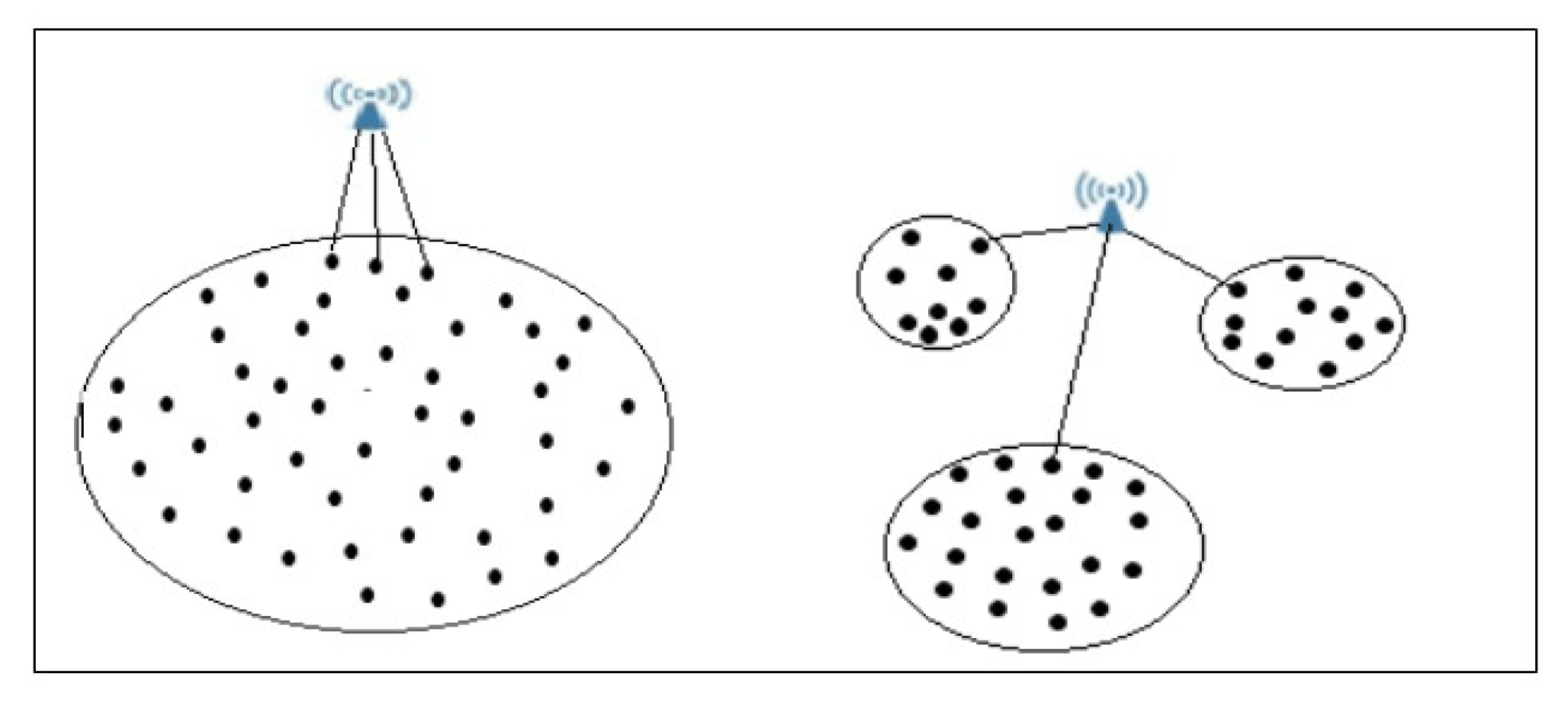
As the nodes are clustered, the fundamental goal is to locate multiple sinks to achieve the longest lifespan, more energy efficiency, and the fastest data delivery to each sink. As a result, a sink placement strategy was required to accomplish the predicted goals for each cluster, where all of these clusters would collectively achieve the large-scale WSN goals. If the sink is situated in a location with a small number of neighbour nodes, they would be regularly used to relay packets to the sink. As a result, these nodes consume more energy, causing the WSN’s lifetime to be shortened. Figure 3 represents a scenario in which the sink has a small number of communication neighbours.
For this situation, we propose a strategy that places the sinks in the appropriate locations so that the number of nodes surrounding the sink is as high as possible. Therefore, we suggest placing the sink in the barycentre of the cluster with a number of nodes greater than a predetermined number ( N threshold ) and in the barycentre of multiple groups that have the fewest number of nodes. In Figure 4, two possible sink locations are in the barycentre of a cluster with more nodes than the threshold using Equation (15) or in the barycentre of the most neighbour clusters (MNC) using Equation (16). The details are formally described as a flowchart in Figure 5, which depicts the network construction in addition to two possible sink locations.
The coordinates of sink k are denoted as sink k x k , y k and determined according to the possible location as follows:
  • When sink k is located in the barycentre of cluster j:
    x k = i = 1 N j C range i x i i = 1 N j C range i y k = i = 1 N j C range i y i i = 1 N j C range i
    where x i and y i are the coordinates of sensor i, which exists in cluster j, C range i is the range communication of sensor i, and N j is the number of sensors in cluster j.
  • When sink k is located in the barycentre of p neighbour clusters:
    x k = i = 1 p C range i x CH i i = 1 p C range i y k = i = 1 p C range i y CH i i = 1 p C range i
    where CH 1 , , CH i , , CH p is the set of p cluster heads of these neighbours’ clusters with communication range ( r 1 , , r i , , r p ) , x CH i and y CH i are the coordinates of cluster head CH i that exists in cluster i, and p is the number of clusters.

4.4. Data Routing and Transmission

A sink creates pathways between CHs and itself once the CHs are picked. Since the BS includes comprehensive topology information, it chooses the best path in such a way that the routing path’s overall energy consumption is as low as possible. Then, before constructing any paths, it classifies the routes into Direct_path, Direct_nodes_CH, and Multi_path_R.
Direct_path is a path over which nodes communicate directly to the sink without any intermediaries, and those nodes are named Direct_nodes_sink. Direct_nodes_CH is a path of all nodes that use only CHs as intermediate nodes to the sink, and Multi_path_R is a path consisting of multiple intermediate nodes excluding CH. During the transmission phase, the sink verifies whether the CH has sufficient remaining energy to participate. Otherwise, it is replaced by another node in the same cluster as the new CH. However, if its distance from the previous CH is not in the communication range of the old CH or the sink (assigned to this cluster), it will not be considered, and the following node with the next-highest Cp value would be considered instead. This process is successfully executed following Algorithm 3.
Algorithm 3: Cluster Head Adjustment
Input:  Old_CH
Output:  New_CH
1. for each SN in a cluster do
2. calculate Cp
3. select node with max Cp
4. if  C range ( old CH , S i ) ≺ d( old CH , S i   )
5.       select the following nodes with max Cp
6. Else
7.       Select S i as New_CH
8. End for
The sink constructs a Route Set (Multi_path_R) for each CH representing all possible paths to the CH. It already generates a Legitimate Route Set (Multi_path_LR), which includes all of the routes with remaining energy over the threshold energy ( E threshold ). We calculate E threshold using Equation (17). A path constitutes several SNs that use multihop communication to send packets from the CH to the sink. Any path with a sensor node with residual energy below a predetermined E threshold is excluded from the Multi_path_LR set.
E threshold = R energy S i n i
where R energy S i is the sum of all nodes’ residual energies of cluster i, and n i is the number of existing sensors in cluster i.
Then, for all Multi_path_LR, the sink computes the cost of energy, which is the sum of the cost of energy of each node on that path. The optimal path between the CH and sink is thought to be that with the lowest energy cost. We calculate the cost of any route by using Equation (18), which is defined as follows:
cost LRj = x = 0 x LRj d ( S i , S i + 1 ) R energy S i
where R energy S i is the residual energy of node S i , and d ( S i , S i + 1 ) is the distance between S i and the next node S i + 1 .
Algorithm 4: Repacking _CH_ Route
Declare
Drect_nodes_sink = {}
Direct_nodes_CH = {}
Multi_path_R = {}
Multi_path_LR = {}
Multi_path_BR = {}             //represents the set of best routes to CH
1.for each S i in nodes
2.         if d( S i   ,   sin k ) < d( S i   ,   CH ) & C range ( S i   , sin k ) > d( S i   ,   sin k ) then
3.              Add S i to Direct_nodes_sink
4.         Else
5.              for each CH do
6.                    if ( E res   ( CH ) < E threshold ) then
7.                         select new CH using Algorithm 3
8.                         If  S i   ͼ N ( CH ) & C range ( S i   ,   CH ) > d( S i   ,   CH ) then
9.                              Add S i to Direct_nodes_CH
10.                         Else
11.                              for each route Rj ∈ Multi_path_R do
12.                                   if ∀ S i ∈ Rj: d( S i , S i + 1 ) < D threshold     | | E R ( S i ) < E threshold then
13.                                       Multi_path_LR = Multi_path_LR ∪ Rj
14.                                   End if
15.                              End for
16.                             for each route LRj ∈ Multi_path_LR
17.                                   Calculate cost(LRj) using Equation (18)
18.                            end for
19.                             BR = min(cost(LR))
20.                         Multi_path_BR = Multi_path_BR ∪ BR
21.                     End if
22.                 End if
23.             End for
24.          End if
25.end for
After selecting all of the cluster heads and constructing the paths, the sink broadcasts the associated CHs (IDs, location). Upon receiving information about the CHs, the nodes submit a join request to the closest CH, while their neighbour nodes store the inf_Table (Cluster Head ID, CH Residual Energy CH_ E res ,   Neighbours   ID , Neighbours location Nb_Loc, Neighbours Residual Energy Nb_ E res ). As a result, each node has full information about its neighbours, including their position, remaining energy, and CH IDs, and each CH is aware of every cluster member.
Now, each node sends the sensed data to the sink, while employing the proposed routing system shown in Algorithm 4. Each node has a complete info_Table, and each member of the cluster iterates through its inf_Table, shortlisting their neighbour nodes, which are called next_hop_Set. All of the nodes between node i and CH from the shortlisted candidates are recorded in next_hop_Set if the following condition is verified: Consider node i, and j, k, l are i‘s neighbours. Nodes j and l are input into next_hop_Set if their distances to the sink are lower than the distance of node i to the sink d i , CH d j , CH and d i , CH d l , CH .
A cluster member directly determines its next hop by selecting the nearest node to the transmitting one verifying d( S i , S i + 1 ) < D threshold , on top of possessing a higher remaining energy than E threshold . Moreover, our proposed model can provide a way to continue operating when a first node is depleted, where each one of its neighbours deletes all information about it from their inf_Table.

5. Simulation and Evaluation

5.1. Simulation Setup

In this section, we describe our relevant simulation tests, which demonstrate the high efficiency and scalability of the suggested approach. The simulation was performed using the network simulator OMNeT++ for the proposed routing protocol in each case (measuring energy consumption and WSN lifetime) over large scale networks, and python scripts were written to implement the corresponding algorithm of clustering. The simulation was conducted on a Dell Inspiron 155,567 computer with an Intel i7 CPU running at 2.4 GHz, Windows 7 (64-bit), and 8 GB of RAM. We used network settings that are identical to those indicated in Table 4 throughout our simulations.
To develop our contribution, we used data from the Stanford Large Network Dataset Collection’s Brightkite dataset, a location-based online social network [65]. There are 5000 nodes in the retrieved dataset, each with its coordinates. We deployed 13 BSs in the network, and we set up the nodes with varied residual energies ranging from 0.3 to 0.9.
As known in the literature, hierarchical protocols and methods are state-of-the-art and based on clustering algorithms such as LEACH [57], DP clustering [61], and HEEMP [39]. We then compared the previous algorithms with our contribution to demonstrate the proposed technique’s performance. LEACH randomly selected and updated the CHs after a fixed amount of time. It also managed to send data from a CH to a specific BS in a random way. In the DP Clustering approach, the CHs are chosen based on the coordinate location of these nodes. The residual energy and node degree are considered while choosing the CHs in the HEEMP. The shortest path is used in all approaches to send the data from the nodes to a specific BS.

5.2. Simulation Results

Table 5 illustrates the fundamental differences relative to the number of hops and clusters. The IAC algorithm is compared to LEACH, HEEMP, and DP clustering to obtain the cluster heads. Our technique shows fewer nodes and clusters with multiple hops than the compared algorithms. Moreover, the maximum number of hops required to reach CH is 3. However, LEACH’s, HEEMP’s, and DP’s clustering are 5, 4, and 4, respectively, since the IAC clustering algorithm is more effective than other clustering techniques on a large scale.

5.2.1. Statistical Results over The Lifetime Based on Various Methods

In this study, we defined the first node’s energy consumption ( FE C ) that ultimately reaches their initial energy ( FE I ) while transmitting the data as a metric to measure the network lifetime t as follows:
t = t f t i
where t f is the instance t when FE C   FE I = 0 , and t i is the instance when the network starts.
The LEACH, HEEMP, DP clustering and the proposed approach were used to investigate the effect of a variable number of sensor nodes on the network’s lifetime. The network’s lifetime was evaluated according to the number of sensors, which ranged from 200 to 1500, as shown in Figure 6a. It is worth noting that the network’s lifetime diminishes as the overall number of sensors grows; this phenomenon occurs mainly because by increasing the number of sensors in the same cluster, the considered sink covers a significant number of nodes’ packets. Our proposed approach shows two possible sink placements: the barycentre of the weighted cluster and the barycentre of the neighbours’ clusters, the Cp factor, and the data routing technique; all of these factors improve the network’s lifetime.
The network’s lifetime obtained by LEACH, HEEMP, and DP clustering, in addition to our proposed approach, is between 114 s and 95 s, 130 s and 118 s, 145 s and 124 s, and 160 s and 132 s, respectively, as the total number of sensors grows between 200 and 600.
The network’s lifetime decreases as the number of sensors grows for all of the compared algorithms. Nevertheless, in all cases, our proposed method has achieved a more extended network lifetime than the other techniques.
Furthermore, in Figure 6a, we note that by increasing the number of sensors, the lifetime lowers (the first node depletes its energy). We can relate that to different assumptions, e.g. that which nodes are depleted first depends on a set of parameters, such as the initial energy (the energy consumption will increase by increasing the number of sensors, and nodes that have lower initial energy probably deplete its energy first), the location (direct or indirect to sinks), the degree (number of sensors in communication range increases by increasing number of sensors), etc. Using the experimental parameters shown in Table 4, the influence of a variable number of clusters on the network’s performance is investigated in this scenario. The number of clusters increases from 10 to 50. The results are depicted in Figure 6b, where it is clear that the network’s lifetime extends as the number of clusters grows, causing each cluster’s size to diminish. Hence, the number of intracluster communications is reduced. On the other hand, the network’s number of CHs increases as the distance between nodes decreases. Therefore, each CH sends its measurements via a shorter link. This criterion, according to the suggested model, indeed increases the network’s lifetime.
The proposed approach, with all of the algorithms, efficiently balances the residual energy among the sensors of each cluster by increasing the number of groups and decreasing their sizes. Thus, the network’s lifetime is increased. Above all, our proposed approach notably provides the best results.
This scheme evaluates the network lifetime performance of four algorithms by fixing the number of sensors and varying the number of sinks, where Figure 6c depicts a scenario in which the number of sensors is N = 500 and the number of sinks ranges from 5 to 15, and Figure 6d depicts a scenario in which the number of sensors is N = 1000 and the number of sinks ranges from 5 to 15. It is obvious that the network’s lifetime increases as the number of sinks increases, resulting in most of the sensor nodes adopting direct transmission to the sink. Therefore, the number of intracommunications is diminished. Overall, Figure 6c,d indicate how the network’s lifetime improves as the number of sinks increases according to the suggested model.
As the total number of sinks grows, the overall number of sensors that communicate directly to the sink increases, implying that the load on the sensors is reduced, the effect of the energy hole phenomena is diminished, and the network’s lifetime is extended. As an outcome, expanding the number of sinks for a given number of sensors extends the sensor’s lifetime. Conversely, compared to our proposed method, the network’s lifetime acquired by the LEACH, HEEMP, and DP clustering approaches is poor in each case. The proposed approach provides the most extended lifetime. It outperforms the results of other algorithms by at least 4%.

5.2.2. Statistical Results on Average Residual Energy Based on Various Methods

We define the average residual energy (ARE) as the difference between the average initial energy (AIE) and the average energy consumed (AEC) by all nodes. The total average residual energy (ARE) is expressed as follows:
ARE = AIE ASEC
AIE = 1 N i = 0 N IE
AEC = 1 N ( i = 1 N E T ( i ) + E R ( i ) )
where IE is the initial energy of node i, and E T ( i )   and   E R ( i ) are the consumption energy for transmission and reception by node i, respectively.
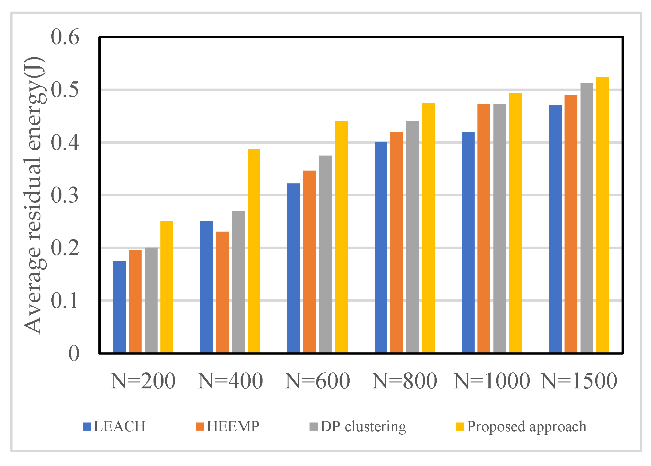
In this section, we study the performance of the algorithms by measuring their average residual energy. In Figure 7, we evaluate the average residual energy performance of four algorithms with the following number of sensors (N): 200, 400, 600, 800, 1000, and 1500. In Figure 8a,b, we evaluate the network-lifetime performance of four algorithms by fixing the number of sensors and varying the number of sinks. Figure 8a depicts a scenario in which the number of sensors is N = 500 and the number of sinks ranges from 5 to 15; Figure 8b depicts a scenario in which the number of sensors is N = 1000 and the number of sinks ranges from 5 to 15. As a result, the outcomes of Figure 7 and Figure 8a,b validate the observation shown in Figure 6a.
In Figure 7, as the total number of sensors grows, the average residual energy of the previous four methods increases significantly. However, the network lifetime generated by our proposed approach remains the longest; thus, it produces the highest average residual energy out of all of the methods.
The scenarios with varying total numbers of sinks are depicted in Figure 8a,b. The average residual energy produced by the four algorithms falls significantly as the number of sensors grows. Similarly, when the overall number of sinks increases, the overall number of SNs reaching the CH directly in each cluster increases. Consequently, the average residual energy increases as well. Compared to other methods, our approach achieved a higher average residual energy.

5.2.3. Statistical Results for Hops Based on Various Methods

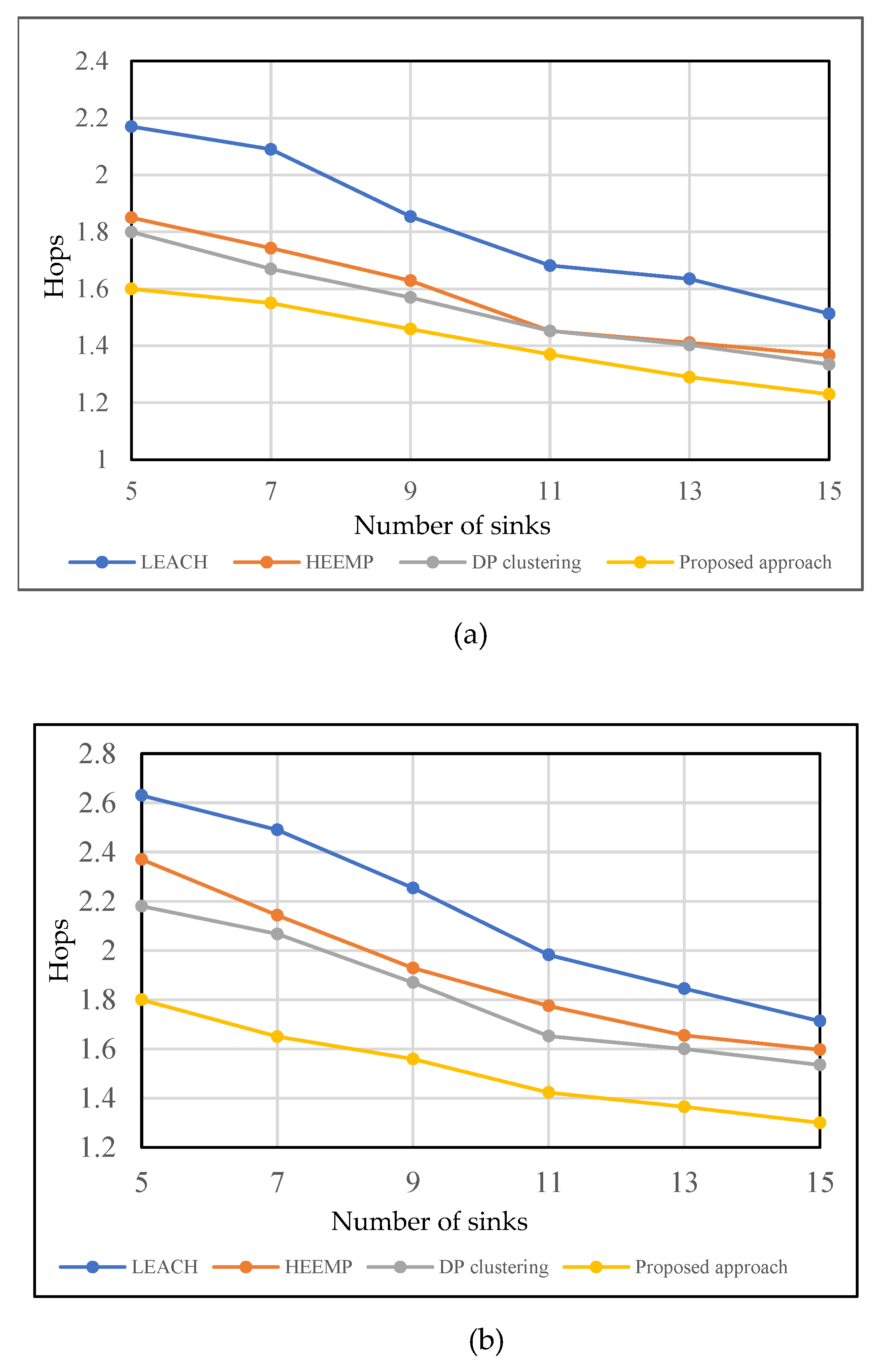
The performance of the routing methods is the main purpose of this section. Figure 9a,b show the equivalent results of the approaches in terms of the average number of hops. It is widely understood that the more prolonged the data transmission path is, the more extended the data transmission delay remains. As a result, reducing the number of hops is a standard network planning method.
This approach’s average number of hops decreases as the total number of sinks grows, as seen in Figure 9a,b. When the overall number of sinks increases, the clusters’ cover ranges decrease. The proposed model has a minimum number of hops in each situation, with an average number of hops less than two, as shown in Figure 9a. As the number of sinks increases to 11, the average number of hops is lowered to between 1.559 and 1.423. Since our suggested technique has established pathways from the sensors to the sinks using the Repacking _CH_ Route algorithm, the sensors were connected to their associated CH and sinks. Even though other algorithms have used the clustering strategy, they have not produced superior outcomes to our proposed study achievement.

6. Conclusions

This paper has dealt with the prevalent issues of high energy consumption, short network lifetime, and data transmission delay in a constrained IoT network. It has notably offered a complete analytical model that combines and resolves all mentioned issues using three aspects: clustering optimization, multiple sink placement, and data routing in heterogeneous WSNs.
We have proposed a practical approach that computes Cp factors to select CHs and then constructs referred clusters, where each cluster has been assigned a specific sink according to a proposed architecture. Unlike existing methods that force each cluster to maintain one unchangeable CH, eventually leading to an enormous energy depletion of the CH nodes given the considerable distance between the cluster members’ nodes and the CH, our suggested method ensures that no CH or intermediate node participates or transmits their data packets with less than an energy threshold and more than a distance threshold. Furthermore, the simulation results have showed that our proposed analytical model reduces the number of hops by more than 4% and increases the residual energy by more than 3% compared to other state-of-the-art algorithms. As a result, it outperforms them in terms of increasing the network’s lifetime, decreasing energy consumption, and reducing data transmission delay using different amounts of sensor nodes.
The proposed work can help researchers and developers build and create applications for highly compressed networks. In addition, applications such as smart farming, smart industry, and smart grids can leverage the data produced by the deployed sensors to develop new applications and services for users.
To increase the extent of our contribution to sink placement, we plan to apply our approach in different environments, such as underwater wireless sensor networks (UWSNs). In this regard, we intend to resolve the fixed sink issue by investigating mobile sinks and to highlight potential trade-offs between performance and cost by corroborating the performance results with some further computational complexity analyses.

Author Contributions

Writing—original draft, S.B.; Writing—review & editing, A.Z., E.H.N. and A.B. All authors have read and agreed to the published version of the manuscript.

Funding

This research received no external funding.

Data Availability Statement

Not applicable.

Conflicts of Interest

The authors declare no conflict of interest.

References

  1. Yousif, M.; Hewage, C.; Nawaf, L. IoT Technologies during and Beyond COVID-19: A Comprehensive Review. Future Internet 2021, 13, 105. [Google Scholar] [CrossRef]
  2. Wang, Y.; Zen, H.; Sabri, M.F.M.; Wang, X.; Kho, L.C. Towards Strengthening the Resilience of IoV Networks—A Trust Management Perspective. Future Internet 2022, 14, 202. [Google Scholar] [CrossRef]
  3. Qian, C.; Liu, X.; Ripley, C.; Qian, M.; Liang, F.; Yu, W. Digital Twin—Cyber Replica of Physical Things: Architecture, Applications and Future Research Directions. Future Internet 2022, 14, 64. [Google Scholar] [CrossRef]
  4. Hackl, J.; Dubernet, T. Epidemic Spreading in Urban Areas Using Agent-Based Transportation Models. Future Internet 2019, 11, 92. [Google Scholar] [CrossRef] [Green Version]
  5. Autili, M.; Di Salle, A.; Gallo, F.; Pompilio, C.; Tivoli, M. A Choreography-Based and Collaborative Road Mobility System for L’Aquila City. Future Internet 2019, 11, 132. [Google Scholar] [CrossRef] [Green Version]
  6. Ramakrishnan, A.M.; Ramakrishnan, A.N.; Lagan, S.; Torous, J. From symptom tracking to contact tracing: A framework to explore and assess COVID-19 apps. Future Internet 2020, 12, 153. [Google Scholar] [CrossRef]
  7. Hyla, T.; Pejaś, J. eHealth Integrity Model Based on Permissioned Blockchain †. Future Internet 2019, 11, 76. [Google Scholar] [CrossRef] [Green Version]
  8. Hammood, D.A.; Rahim, H.A.; Alkhayyat, A.; Ahmad, R.B. Body-to-Body Cooperation in Internet of Medical Things: Toward Energy Efficiency Improvement. Future Internet 2019, 11, 239. [Google Scholar] [CrossRef] [Green Version]
  9. Zannou, A.; Boulaalam, A.; Nfaoui, E.H. System service provider–customer for IoT (SSPC-IoT). In Embedded Systems and Artificial Intelligence; Springer: Berlin/Heidelberg, Germany, 2020; pp. 731–739. [Google Scholar]
  10. Trakadas, P.; Simoens, P.; Gkonis, P.; Sarakis, L.; Angelopoulos, A.; Ramallo-González, A.P.; Skarmeta, A.; Trochoutsos, C.; Calvο, D.; Pariente, T.; et al. An artificial intelligence-based collaboration approach in industrial iot manufacturing: Key concepts, architectural extensions and potential applications. Sensors 2020, 20, 5480. [Google Scholar] [CrossRef]
  11. Sayeed, A.; Verma, C.; Kumar, N.; Koul, N.; Illés, Z. Approaches and Challenges in Internet of Robotic Things. Future Internet 2022, 14, 265. [Google Scholar] [CrossRef]
  12. Parada, R.; Palazón, A.; Monzo, C.; Melià-Seguí, J. RFID Based Embedded System for Sustainable Food Management in an IoT Network Paradigm. Future Internet 2019, 11, 189. [Google Scholar] [CrossRef] [Green Version]
  13. Djukanovic, G.; Kanellopoulos, D.N.; Popovic, G. Evaluation of a UAV-Aided WSN for Military Operations: Considering Two Use Cases of UAV. Int. J. Interdiscip. Telecommun. Netw. (IJITN) 2022, 14, 1–16. [Google Scholar] [CrossRef]
  14. Sam, A.J.; Mahamuni, C.V. A Wireless Sensor Network (WSN) Prototype for Scouting and Surveillance in Military and Defense Operations using Extended Kalman Filter (EKF) and FastSLAM. SSRN Electron. J. 2022. [Google Scholar] [CrossRef]
  15. Ahmad, R.; Wazirali, R.; Abu-Ain, T. Machine Learning for Wireless Sensor Networks Security: An Overview of Challenges and Issues. Sensors 2022, 22, 4730. [Google Scholar] [CrossRef] [PubMed]
  16. Cureau, R.J.; Pigliautile, I.; Pisello, A.L. A New Wearable System for Sensing Outdoor Environmental Conditions for Monitoring Hyper-Microclimate. Sensors 2022, 22, 502. [Google Scholar] [CrossRef] [PubMed]
  17. Fascista, A. Toward Integrated Large-Scale Environmental Monitoring Using WSN/UAV/Crowdsensing: A Review of Applications, Signal Processing, and Future Perspectives. Sensors 2022, 22, 1824. [Google Scholar] [CrossRef] [PubMed]
  18. Bouarourou, S.; Boulaalam, A.; Nfaoui, E.H. A bio-inspired adaptive model for search and selection in the Internet of Things environment. PeerJ Comput. Sci. 2021, 7, e762. [Google Scholar] [CrossRef]
  19. Bouarourou, S.; Zannou, A.; Boulaalam, A.; Nfaoui, E.H. Sensors Deployment in IoT Environment. In Proceedings of the International Conference on Digital Technologies and Applications, Fez, Morocco, 15–20 December 2022; pp. 276–283. [Google Scholar]
  20. Nazib, R.; Moh, S. Sink-Type-Dependent Data-Gathering Frameworks in Wireless Sensor Networks: A Comparative Study. Sensors 2021, 21, 2829. [Google Scholar] [CrossRef]
  21. Zannou, A.; Boulaalam, A.; Nfaoui, E.H. SIoT: A New Strategy to Improve the Network Lifetime with an Efficient Search Process. Future Internet 2020, 13, 4. [Google Scholar] [CrossRef]
  22. Mishra, S.; Thakkar, H. Features of WSN and Data Aggregation techniques in WSN: A Survey. Int. J. Eng. Innov. Technol.(IJEIT) 2012, 1, 264–273. [Google Scholar]
  23. Oyman, E.; Ersoy, C. Multiple sink network design problem in large scale wireless sensor networks. In Proceedings of the 2004 IEEE International Conference on Communications (IEEE Cat. No.04CH37577), Paris, France, 20–24 June 2004; pp. 3663–3667. [Google Scholar] [CrossRef]
  24. Safa, H.; Moussa, M.; Artail, H. An energy efficient Genetic Algorithm based approach for sensor-to-sink binding in multi-sink wireless sensor networks. Wirel. Netw. 2013, 20, 177–196. [Google Scholar] [CrossRef]
  25. Wan, R.; Xiong, N.; Loc, N.T. An energy-efficient sleep scheduling mechanism with similarity measure for wireless sensor networks. Hum. -Cent. Comput. Inf. Sci. 2018, 8, 18. [Google Scholar] [CrossRef] [Green Version]
  26. Razzaque, M.A.; Dobson, S. Energy-Efficient Sensing in Wireless Sensor Networks Using Compressed Sensing. Sensors 2014, 14, 2822–2859. [Google Scholar] [CrossRef] [PubMed] [Green Version]
  27. Bangash, J.I.; Abdullah, A.H.; Anisi, M.H.; Khan, A.W. A Survey of Routing Protocols in Wireless Body Sensor Networks. Sensors 2014, 14, 1322–1357. [Google Scholar] [CrossRef] [PubMed] [Green Version]
  28. Malik, A.; Khan, M.Z.; Faisal, M.; Khan, F.; Seo, J.-T. An Efficient Dynamic Solution for the Detection and Prevention of Black Hole Attack in VANETs. Sensors 2022, 22, 1897. [Google Scholar] [CrossRef] [PubMed]
  29. Lansky, J.; Ali, S.; Rahmani, A.M.; Yousefpoor, M.S.; Yousefpoor, E.; Khan, F.; Hosseinzadeh, M. Reinforcement Learning-Based Routing Protocols in Flying Ad Hoc Networks (FANET): A Review. Mathematics 2022, 10, 3017. [Google Scholar] [CrossRef]
  30. Curry, R.M.; Smith, J.C. A survey of optimization algorithms for wireless sensor network lifetime maximization. Comput. Ind. Eng. 2016, 101, 145–166. [Google Scholar] [CrossRef] [Green Version]
  31. Gawade, R.D.; Nalbalwar, S.L. A Centralized Energy Efficient Distance Based Routing Protocol for Wireless Sensor Networks. J. Sens. 2016, 2016, 1–8. [Google Scholar] [CrossRef] [Green Version]
  32. Tsoumanis, G.; Oikonomou, K.; Koufoudakis, G.; Aïssa, S. Energy-efficient sink placement in wireless sensor networks. Comput. Netw. 2018, 141, 166–178. [Google Scholar] [CrossRef]
  33. Jari, A.; Avokh, A. PSO-based sink placement and load-balanced anycast routing in multi-sink WSNs considering compressive sensing theory. Eng. Appl. Artif. Intell. 2021, 100, 104164. [Google Scholar] [CrossRef]
  34. Heinzelman, W.R.; Chandrakasan, A.; Balakrishnan, H. Energy-efficient communication protocol for wireless microsensor networks. In Proceedings of the 33rd Annual Hawaii International Conference on System Sciences, Maui, Hawaii, 7 January 2000; Volume 2, p. 10. [Google Scholar]
  35. Ghafoor, S.; Rehmani, M.H.; Cho, S.; Park, S.-H. An efficient trajectory design for mobile sink in a wireless sensor network. Comput. Electron. Eng. 2014, 40, 2089–2100. [Google Scholar] [CrossRef]
  36. Lindsey, S.; Raghavendra, C. PEGASIS: Power-efficient gathering in sensor information systems. In Proceedings of the Aerospace Conference Proceedings, Big Sky, MT, USA, 9–16 March 2002; Volume 3, pp. 1125–1130. [Google Scholar]
  37. Han, Z.; Wu, J.; Zhang, J.; Liu, L.; Tian, K. A general self-organized tree-based energy-balance routing protocol for wireless sensor network. IEEE Trans. Nucl. Sci. 2014, 61, 732–740. [Google Scholar] [CrossRef]
  38. Pantazis, N.A.; Nikolidakis, S.A.; Vergados, D.D. Energy-Efficient Routing Protocols in Wireless Sensor Networks: A Survey. IEEE Commun. Surv. Tutor. 2012, 15, 551–591. [Google Scholar] [CrossRef]
  39. Sajwan, M.; Gosain, D.; Sharma, A.K. Hybrid energy-efficient multi-path routing for wireless sensor networks. Comput. Electron. Eng. 2018, 67, 96–113. [Google Scholar] [CrossRef]
  40. Bonabeau, E.; Dorigo, M.; Theraulaz, G.; Theraulaz, G. Swarm Intelligence: From Natural to Artificial Systems; Oxford University Press: Oxford, UK, 1999. [Google Scholar]
  41. Sarathy, R.; Shetty, B.; Sen, A. A constrained nonlinear 0–1 program for data allocation. Eur. J. Oper. Res. 1997, 102, 626–647. [Google Scholar] [CrossRef]
  42. Handl, J.; Meyer, B. Ant-based and swarm-based clustering. Swarm Intell. 2007, 1, 95–113. [Google Scholar] [CrossRef]
  43. Jevtić, A. Swarm intelligence: Novel tools for optimization, feature extraction, and multi-agent system modeling. Telecomunicacion. Ph.D. Thesis, Technical University of Madrid, Madrid, Spain, 2011. [Google Scholar]
  44. Jevtić, A.; Quintanilla-Domínguez, J.; Barrón-Adame, J.M.; Andina, D. Image segmentation using ant system-based clustering algorithm. In Proceedings of the Soft Computing Models in Industrial and Environmental Applications, 6th International Conference SOCO 2011, Bilbao, Spain, 22–24 September 2011; pp. 35–45. [Google Scholar]
  45. Dorigo, M.; Birattari, M. Swarm intelligence. Scholarpedia 2007, 2, 1462. [Google Scholar] [CrossRef]
  46. Cui, X.; Potok, T.E.; Palathingal, P. Document clustering using particle swarm optimization. In Proceedings of the 2005 IEEE Swarm Intelligence Symposium, Pasadena, CA, USA, 8–10 June 2005; SIS 2005. pp. 185–191. [Google Scholar]
  47. Zhao, C.; Wu, C.; Wang, X.; Ling, B.W.-K.; Teo, K.L.; Lee, J.-M.; Jung, K.-H. Maximizing lifetime of a wireless sensor network via joint optimizing sink placement and sensor-to-sink routing. Appl. Math. Model. 2017, 49, 319–337. [Google Scholar] [CrossRef]
  48. Kabakulak, B. Sensor and sink placement, scheduling and routing algorithms for connected coverage of wireless sensor networks. Ad Hoc Netw. 2019, 86, 83–102. [Google Scholar] [CrossRef] [Green Version]
  49. Hong, Z.; Wang, R.; Li, X. A clustering-tree topology control based on the energy forecast for heterogeneous wireless sensor networks. IEEE/CAA J. Autom. Sin. 2016, 3, 68–77. [Google Scholar] [CrossRef]
  50. Mukherjee, S.; Amin, R.; Biswas, G.P. Design of routing protocol for multi-sink based wireless sensor networks. Wirel. Netw. 2019, 25, 4331–4347. [Google Scholar] [CrossRef]
  51. Cayirpunar, O.; Tavli, B.; Kadioglu-Urtis, E.; Uludag, S. Optimal Mobility Patterns of Multiple Base Stations for Wireless Sensor Network Lifetime Maximization. IEEE Sens. J. 2017, 17, 7177–7188. [Google Scholar] [CrossRef]
  52. Sapre, S.; Mini, S. A differential moth flame optimization algorithm for mobile sink trajectory. Peer—Peer Netw. Appl. 2020, 14, 44–57. [Google Scholar] [CrossRef]
  53. Gosain, D.; Snigdh, I.; Sajwan, M. DSERR: Delay Sensitive Energy Efficient Reliable Routing Algorithm. Wirel. Pers. Commun. 2017, 97, 3685–3704. [Google Scholar] [CrossRef]
  54. Sohraby, K.; Minoli, D.; Znati, T. Wireless sensor networks: Technology Protocols; Applications; John Wiley & Sons: Hoboken, NJ, USA, 2007. [Google Scholar]
  55. Heinzelman, W.R.; Kulik, J.; Balakrishnan, H. Adaptive protocols for information dissemination in wireless sensor networks. In Proceedings of the 5th annual ACM/IEEE International Conference on Mobile Computing and Networking, Washington, DC, USA, 15–20 August 1999; pp. 174–185. [Google Scholar]
  56. Akyildiz, I.F.; Su, W.; Sankarasubramaniam, Y.; Cayirci, E. Wireless sensor networks: A survey. Comput. Netw. 2002, 38, 393–422. [Google Scholar] [CrossRef] [Green Version]
  57. Handy, M.; Haase, M.; Timmermann, D. Low energy adaptive clustering hierarchy with deterministic cluster-head selection. In Proceedings of the 4th International Workshop on Mobile and Wireless Communications Network, Lake Buena Vista, FL, USA, 21–23 May 2003. [Google Scholar] [CrossRef]
  58. Manjeshwar, A.; Agrawal, D.P. TEEN: ARouting Protocol for Enhanced Efficiency in Wireless Sensor Networks. ipdps 2001, 1, 189. [Google Scholar]
  59. Tirani, S.P.; Avokh, A. On the performance of sink placement in WSNs considering energy-balanced compressive sensing-based data aggregation. J. Netw. Comput. Appl. 2018, 107, 38–55. [Google Scholar] [CrossRef]
  60. Sun, P.; Wu, L.; Wang, Z.; Xiao, M.; Wang, Z. Sparsest Random Sampling for Cluster-Based Compressive Data Gathering in Wireless Sensor Networks. IEEE Access 2018, 6, 36383–36394. [Google Scholar] [CrossRef]
  61. Zannou, A.; Boulaalam, A.; Nfaoui, E.H. Data Flow Optimization in the Internet of Things. Stat. Optim. Inf. Comput. 2022, 10, 93–106. [Google Scholar] [CrossRef]
  62. Lumer, E.D.; Faieta, B. Diversity and adaptation in populations of clustering ants. In Proceedings of the Third International Conference on Simulation of Adaptive Behavior: From Animals to Animats 3: From Animals to Animats 3, Brighton, UK, 8–12 August 1994; pp. 501–508. [Google Scholar]
  63. Deneubourg, J.-L.; Goss, S.; Franks, N.; Sendova-Franks, A.; Detrain, C.; Chrétien, L. The dynamics of collective sorting robot-like ants and ant-like robots. In From Animals to Animats: Proceedings of the First International Conference on Simulation of Adaptive Behavior; MIT Press: Cambridge, MA, USA, 1990; pp. 356–365. [Google Scholar]
  64. Nanda, S.J.; Panda, G. A survey on nature inspired metaheuristic algorithms for partitional clustering. Swarm EComput. 2014, 16, 1–18. [Google Scholar] [CrossRef]
  65. Grover, A.; Leskovec, J. node2vec: Scalable feature learning for networks. In Proceedings of the 22nd ACM SIGKDD International Conference on Knowledge Discovery and Data Mining, San Francisco, CA, USA, 13–17 August 2016; pp. 855–864. [Google Scholar]
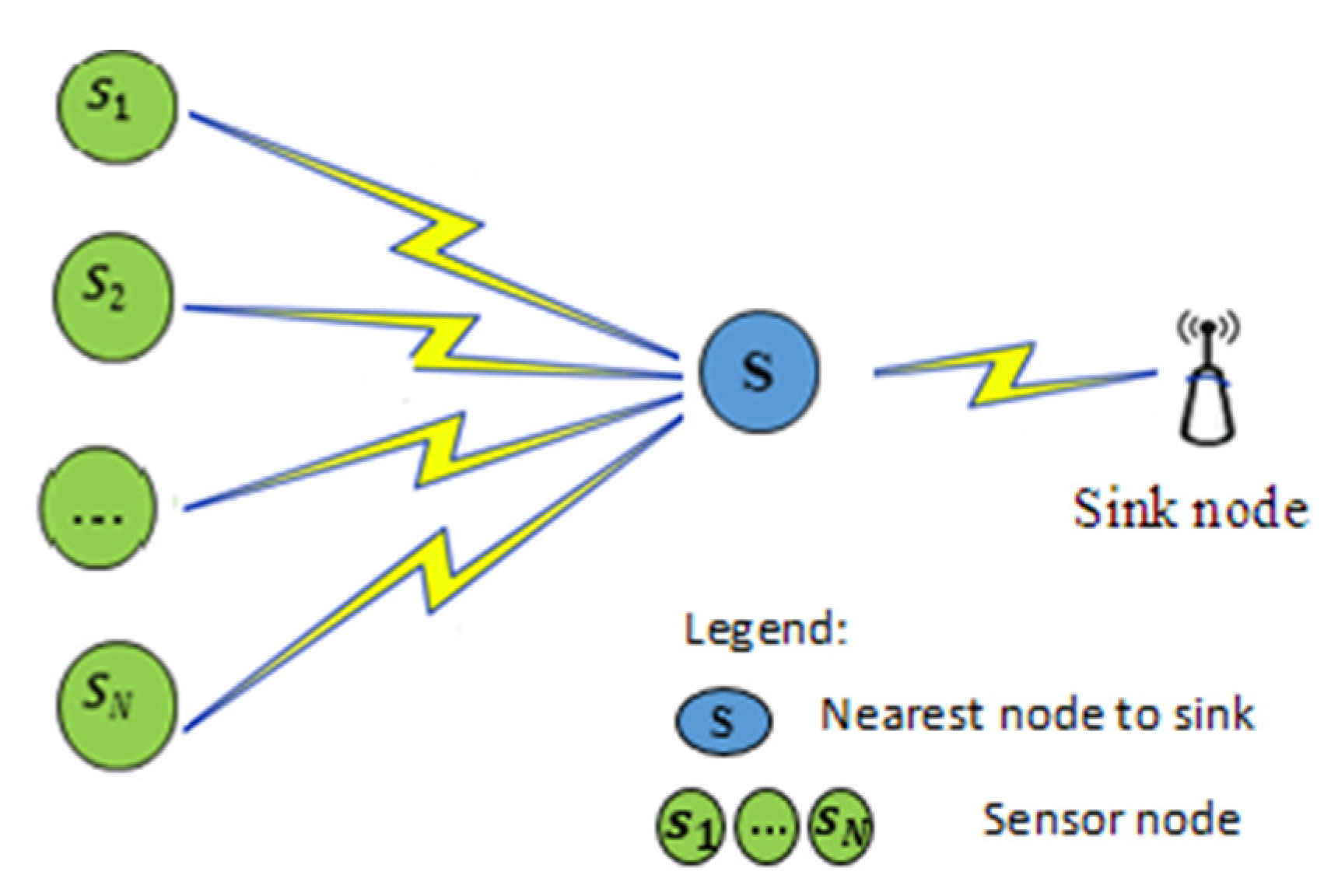
Figure 1. Data transmission using neighbouring nodes.
Futureinternet 15 00075 g001
Figure 2. Data transmission using cluster head.
Futureinternet 15 00075 g002
Figure 3. Sink location in low-neighbour area.
Futureinternet 15 00075 g003
Figure 4. WSN construction with our proposed strategy.
Futureinternet 15 00075 g004
Figure 5. Flow chart of sink placement.
Futureinternet 15 00075 g005
Figure 6. Network lifetime vs. (a) number of sensors, (b) number of cluster heads, varying the number of sinks from 5 to 15 when fixing the number of sensors (N)., (c)-N = 500, (d)-N = 1000.
Futureinternet 15 00075 g006
Figure 7. Average residual energy with a wide-ranging number of sensors N.
Futureinternet 15 00075 g007
Figure 8. Average residual energy when fixing the number of sensors (N) and varying the number of sinks (M) from 5 to 15. (a)-N = 500, (b)-N = 1000.
Futureinternet 15 00075 g008
Figure 9. Average hops with a variable number when fixing the number of sensors (N) and varying the number of sinks (M) from 5 to 15. (a)-N = 500, (b)-N = 1000.
Futureinternet 15 00075 g009
Table 1. Functional comparison of the most recent studies for sink placement.
Authors
\Year
Sink TypeNumber of SinksClustering MechanismNetwork Constraints ConsideredKeys Points:
Algorithms
/Protocols
Limitation/
Constraint
Network LifetimeEnergy
Consumption
Data
Routing
Sapre et al. (2021) [52] mobilesingleCombines meta-heuristic differential moth flame optimization (MFO) and differential evolution (DE) as DMFO to place the relay nodes to cluster the WSN.Coverage time has not been considered in this model. As a result, it impacts the lifetime performance of sensor networks.
Kabakulak (2019) [48] staticmultiple×SPSRC, a mixed integer programming formulation, determines the best placement for sensors and sinks, as well as sensor active/standby times and data transmission paths from each active node to its assigned sink.This method assigns the task of selecting alive nodes to lower energy sensor nodes; this raises dead nodes and breaks network connections.
Tsoumanis et al. (2018) [32] staticmultiple××A k-median facility location problem.Focus only on sink deployment.
Cayirpunar (2017) [51] mobilemultiple×The mixed integer programming (MIP) framework defines network lifetime (NL) for multiple mobile BSs under various mobility patterns.The method fails to determine the data transmission delay and throughput.
Zhao et al. (2017) [47] staticmultipleSink location and sensor-to-sink route optimization using the PSO algorithm.The protocol is limited to sinks in the monitoring zone.
Hong et al. (2016) [49] staticmultiple×CTEF is a clustering-tree topology control technique based on the energy forecast for conserving energy and guaranteeing network load balancing while considering connection quality and packet loss rate.This solution does not address the issue of data transmission delay.
Ghafoor et al. (2014) [35] Mobilesingle×Based on the Hilbert curve, a mobile sink trajectory is created.Collecting data in the direction of the Hilbert curve does not guarantee that the load on the network’s nodes will be balanced and energy consumption will rise.
Oyman et al. (2004) [23] staticMultiple×Sink placement using the k-means algorithm.The method is unsuitable for large-scale networks, and the pathway from sensors to sinks must be considered.
Table 2. Functional comparison of latest studies for sink routing protocol.
Authors\
Year
ApproachClustering MechanismNetwork Constraints
Considered
CH
Selection
Criteria
Data
Transmission
Drawbacks/Limitations
Network LifetimeEnergy
Consumption
Zannou et al. (2022) [61]DP clustering-Coordinate’s location of the node.Multi-hopIt is likely to select a low-energy node as CH.
Sajwan et al. (2018) [39]HEEMP-Residual energy
-Node degree
Multi-hopThe nodes near the CH node in the proposed multi-hop intra-cluster communications receive multiple messages and collect them without considering whether they can handle the load or not.
Jari et al. (2018) [33]MPAR& EMPAR-Residual energy
-distance
Multi-hopThe network becomes costly when several sinks are involved. Finding the best position becomes increasingly challenging as the number of sinks increases.
Pantazis et al. (2018) [38]CDG-At the centre of evenly divided regionsMulti-hopIt considers network properties, but ignores CDG features.
Gawade et al. (2016) [31]CEED-Dissipation energy of node
-Distance to sink
Multi-hopIt puts a tremendous load on CH.
Han et al. (2014) [37]GSTEB-Maximum residual energy (as root node)Multi-hopIt consumes more energy due to direct routing. The significant number of control packets has a higher energy overhead.
Lindsey et al. (2012) [36]PEGASIS-Each node selected as a leaderMulti-hopThere is a significant delay for remote nodes, and the single leader mechanism can generate congested.
Heinzelman et al. (2000) [34]DT-Random thresholdMulti-hopIt ignores the distance between the Cluster Head and the BS.
Table 3. Symbol denotation.
NotationDescription
N Number of sensor nodes
MNumber of sinks
S i The sensor i
d ( S i , S j )Distance between the sensor S i and the sensor S j .
min_d( S i   ,   S j )Minimum Distance between the sensor S i and the sensor S j .
CHs All cluster head nodes in the network.
BSBase station/Sink.
CH j Cluster head of the j th cluster.
Cp i Chance of picking a node i factor.
C range ( S i , CH j )Communication range between a node S i and the CH j node.
clust i The i th cluster.
| clust i | Number of nodes in the cluster i.
S(i)A set of alive neighboors of node i.
MNCThe most neighbors clusters.
MNC Number of nodes in the cluster MNC.
RjThe   j th multi path route.
BRThe route between CH and a node with minimum cost value (Best Route).
R energy The residual energy.
min _ R energy The minimum residual energy in the considering network.
max _ R energy The maximum residual energy in the considering network.
E R The energy required for reception data.
E T The energy required for transmission data.
E mp The energy required in multi path model.
E D The energy required in Direct path model.
N ant Number of ants
N Iteration Number of iterations
Table 4. Setting Considered For Our Simulations.
ParametersValues
N1000
M13
CH30
N ant 500
α 0.5
S30 m × 30 m
Δ α 0.05
K 1 0.1
K 2 0.15
N Iteration 500
min _ R energy 0.3 J
max _ R energy 0.9 J
E R - elec 20 nJ/bit
E T - elec 45 nJ/bit
E fs 10   Pj / bit / m 2
E mp 0.0013   Pj / bit / m 4
C range [10 m, 30 m]
D threshold 30 m
Initial _   E threshold 0.2J
Table 5. Comparison of the efficiency of sensors affectations for different clustering algorithm.
ApproachNumber of
Nodes with
1-Hop (%)
Number of
Nodes with
2-Hop (%)
Number of
Nodes with
3-Hop (%)
Number of
Nodes with
4-Hop (%)
Number of
Nodes with
5-Hop (%)
LEACH [57]87.24.83.52.52
HEEMP [39]92.53.52.51.50
DP clustering [61]93.53.52.80.20
Our proposed96.521.500
Disclaimer/Publisher’s Note: The statements, opinions and data contained in all publications are solely those of the individual author(s) and contributor(s) and not of MDPI and/or the editor(s). MDPI and/or the editor(s) disclaim responsibility for any injury to people or property resulting from any ideas, methods, instructions or products referred to in the content.