Article

Thermal Insulating and Mechanical Properties of Cellulose Nanofibrils Modified Polyurethane Foam Composite as Structural Insulated Material

College of Materials Science and Engineering, Nanjing Forestry University, Nanjing 210037, China
*
Author to whom correspondence should be addressed.
Forests 2019, 10(2), 200; https://doi.org/10.3390/f10020200
Submission received: 3 February 2019 / Revised: 19 February 2019 / Accepted: 19 February 2019 / Published: 25 February 2019
(This article belongs to the Special Issue Wood Productions and Renewable Materials)

Abstract

:
Cellulose nanofibrils (CNF) modified polyurethane foam (PUF) has great potential as a structural insulated material in wood construction industry. In this study, PUF modified with spray-dried CNF was fabricated and the physical and mechanical performance were studied. Results showed that CNF had an impact on the foam microstructure by increasing the precursor viscosity and imposing resistant strength upon foaming. In addition, the intrinsic high mechanical strength of CNF imparted an extra resistant force against cells expansion during the foaming process and formed smaller cells which reduced the chance of creating defective cells. The mechanical performance of the foam composite was significantly improved by introducing CNF into the PUF matrix. Compared with the PUF control, the specific bending strength, specific tensile strength, and specific compression strength increased up to three-fold for the CNF modified PUF. The thermal conductivity of PUF composite was mainly influenced by the closed cell size. The introduction of CNF improved thermal insulating performance, with a decreased thermal conductivity from 0.0439 W/mK to 0.02724 W/mK.

1. Introduction

Structural insulated panels (SIP) have drawn extensive attention in North America and Europe for both residential and commercial constructions due to their excellent performance, such as light-weight, strong mechanical properties, and thermal insulation [1,2,3,4]. SIP consists of two face layers and one core layer which is usually made of expanded polystyrene foam (EPS), extruded polystyrene (XPS), and polyurethane foam (PUF), of which PUF has over 50% market share [5]. Rigid PUF, invented and commercialized during the 1950s, attracts much attention due to its low density, strong mechanical properties, great thermal properties, and low thermal conductivity [6,7,8,9]. Traditional PUF is usually fabricated by the two-part reaction which consists of isocyanate as part A and petroleum-based polyols (polyol polyether or polyol polyester) and additives as part B. Nevertheless, the petroleum-based polyols had an adverse impact on the environment due to their non-renewability and difficulty to degrade in the environment [10]. Recently, considerable effort has been made to find bio-renewable raw materials to replace the petroleum-based raw materials. The derivatives of various natural materials including starch and soy flour were intensively investigated. In addition, vegetable oil-based polyols were reported as a substitute for the manufacture of PUF [11,12]. However, it involved complicated chemical modification of the vegetable oil. To the best of our knowledge, there are few studies that have been reported to use spray-dried cellulose nanofibrils (CNF) to substitute petroleum-based polyols [13]. Nevertheless, no paper has been reported to apply the novel CNF modified PUF composite as structural insulated material.
Recently, cellulose and its derivatives have been widely studied as an alternative feedstock for the synthesis of PUF due to their abundancy and prominent properties [10,14,15,16,17,18,19]. CNF, a smaller form of cellulose, consists of nano-grade cellulose whiskers with a high Young’s modulus, low thermal expansion coefficient, and high flexibility [20]. CNF is considered a promising substitute to conventional polyols, since it has highly reactive surfaces containing a huge number of hydroxyl groups at C2, C3, and C6 positions [19,21,22,23,24,25,26,27,28]. As is known that there are two main reactions involved in the fabrication of PUF: the essential polymerization reaction between hydroxyl group in polyols and isocyanate group forms the skeleton of PUF; and the reaction between foaming agent (e.g., water) and isocyanate group generates blowing gas (e.g., carbon dioxide) that produce the cellular structure of PUF [29]. The hydroxyl groups in CNF are readily reactive to isocyanate groups and form a crosslinking foam matrix. There were several studies investigating CNF as a reinforcing agent in different forms of polymers [30,31,32,33]. Studies of dispersing fillers into PUF matrix have also been reported to improve mechanical and thermal performances of the foam [34]. However, there was no study on using CNF as a direct precursor to form chemical bond with isocyanate and improving mechanical and thermal properties of SIP. CNF could be dispersed in water, freeze dried as CNF aerogels, and spray dried as CNF powders, depending on different applications [35]. Spray-dried CNF was selected as the petroleum-based polyol substitute in this work, since water is also a popular feedstock to produce blown agent during the synthesis of PUF and only a small amount is needed. On the other hand, since CNF aerogel could not be mixed uniformly with petroleum-based polyols, only spray-dried CNF was suitable to replace petroleum-based polyols.
In this study, our objective was to develop a simple method to fabricate CNF modified PUF composite. A weight ratio of up to 30% (based on total parts per weight (Pbw) of polyols) of CNF was added to replace the petroleum-based polyol (i.e., PEG-400). The microstructural, mechanical, and thermal properties of the CNF modified PUF composite were studied and compared with the PUF control by scanning electron microscopy (SEM), Fourier transform infrared spectroscopy (FTIR), thermal constants analyzer, and universal mechanical testing. In addition, the mechanism of CNF on the property improvement of the foam composite was discussed.

2. Materials and Methods

2.1. Materials

The traditional two-part reaction was adopted to synthesize PUF [36]. Part A consists of isocyanate (i.e., polymethylene polyphenylisocyanate) (PAPI™27 Polymeric MDI) (Dow Chemical, Midland, MI, USA). Part B not only contains polyols (i.e., polyethylene glycol (PEG-400) (Sigma Aldrich, St. Louis, MO, USA), spray-dried CNF (the process development center at University of Maine, Orono, ME, USA), but also catalyst (DABCO T12 (Air Products, Allentown, PA, USA), deionized water, and surfactant (DABCO DC5357 (Air Products, Allentown, PA, USA). Part A and B were mixed up during the synthesis of PUF.

2.2. Fabrication of PUF

Table 1 lists foaming formulation with various replacement ratios of CNF. PUF0 denominates the PUF control without replacement of CNF, PUF20, and PUF30 denominates PUF modified with 20% and 30% CNF (based on the total Pbw of polyols), respectively. For the production of PUF, all materials in part B were first mixed up and mechanically stirred for about 15 min in a 1000 mL polypropylene beaker until homogeneous mixture was obtained. Then, part A was added into the mixture and vigorously stirred for 30 s, after which the mixture was poured into a 355 × 64 × 100 mm reaction box where the foaming process started. The final products were cured overnight in a vacuum oven at 50 °C. The cured foams were then cut into standard sizes and density was defined as mass by unit volume of the foam. Then the foams were conditioned at 20 °C and 50% relative humidity before testing. In this study, the Pbw of PAPI27 was calculated based on Equation (1)
Pbw PAPI 27   =   ( Pbw P E G 400 Eq . wt . P E G 400 + Pbw C N F Eq . wt . C N F + Pbw H 2 O Eq . wt . H 2 O ) I n d e x N C O / O H Eq . wt . P A P I 27
where the −NCO/−OH index was set at 1.1 to ensure complete reaction of −OH groups. Eq.wt. is the abbreviation of equivalent weight. The Eq.wt. is used to calculate the grams of an ingredient needed for one equivalent of reactive groups. The eq.wt. of polyols was defined by Equation (2)
Eq . wt . p o l y o l = 56.1 × 1000 hydroxyl   number
where 56.1 is the atomic weight of potassium hydroxide and 1000 is the number of milligrams in one gram of sample, and the hydroxyl number of PEG-400 and CNF, was determined according to ASTM standard D4274-05D. The eq.wt. of water was 9, and that of PAPI27 was expressed by Equation (3)
Eq . wt . P A P I 27 = 42 weight   percent N C O %
where 42 is the atomic weight of −NCO and weight percent NCO was provided by the manufacture.

2.3. Microstructure Characterization

The microstructure of PUF and CNF-PUF samples was analyzed by a scanning electron microscope FEI Quanta 200 SEM (Thermo Fisher, Hillsboro, OR, USA). The operational voltage was set at 5 kV. The foam samples were cut into a size of 10 mm × 10 mm × 3 mm and placed onto carbon tapes, and then sputter coated with gold using a denton high vacuum coating system (Moorestown, NJ, USA) for 1 min under vacuum. ImageJ (https://imagej.nih.gov/ij/) was used to obtain the cell dimension. The closed cell content was determined according to ASTM standard (ASTM D6226-15).

2.4. Fourier Transform Infrared Spectroscopy (FT-IR)

The Fourier transform infrared spectroscopy of foam samples were performed by a Thermo Nicolet iS10 FTIR spectrometer (Thermo Scientific, Verona, WI, USA). An attenuated total reflection (ATR) probe with a Smart iTR Basic accessory was adopted in the spectra scan. A total 64 scans were utilized for the absorbance spectra, and the scanning range was set between 4000 and 400 cm−1 with resolution of 4 cm−1. After the scan, the spectra were automated processed with baseline correction, average, and normalization using an internal software.

2.5. Mechanical Test

The compression test of the foam samples was performed by a universal testing machine (Instron 5869, Norwood, MA, USA) according to ASTM C365M-16. A 1 kN loading cell and a speed of 1.27 mm/min were selected. Samples measuring 12.7 × 12.7 × 12.7 mm were cut from the fabricated foams. The foam rising direction was marked as the compression direction. The four-point bending test was conducted according to ASTM D7250M-16 using the same universal testing machine (Instron 5869, Norwood, MA, USA) and the same loading cell. The speed of the crosshead was set at 6.35 mm/min. The span was 304.8 mm. The tensile test was performed according to ASTM D695-10 using the same universal testing machine (Instron 55566, Norwood, MA, USA) and the same loading cell. The speed of the crosshead was set at 5.08 mm/min. For all tests, 10 samples were tested for each group.

2.6. Thermal Conductivity Test

The thermal conductivity of CNF-PUF was measured using a Hot Disk TPS 1500 thermal constants analyzer (ThermTest, Fredericton, Canada) following the ISO/DIS 22007-2.2 standard, Kapton 8563 sensor was used for the analysis. Measurement time ranged from 40 to 80 s, depending on the test results. The laboratory temperature was maintained at 20 ± 1 °C and the relative humidity was 65 ± 2% during the measurements. Three measurements were made for each group, then the average value and the standard deviation were calculated.

3. Results and Discussions

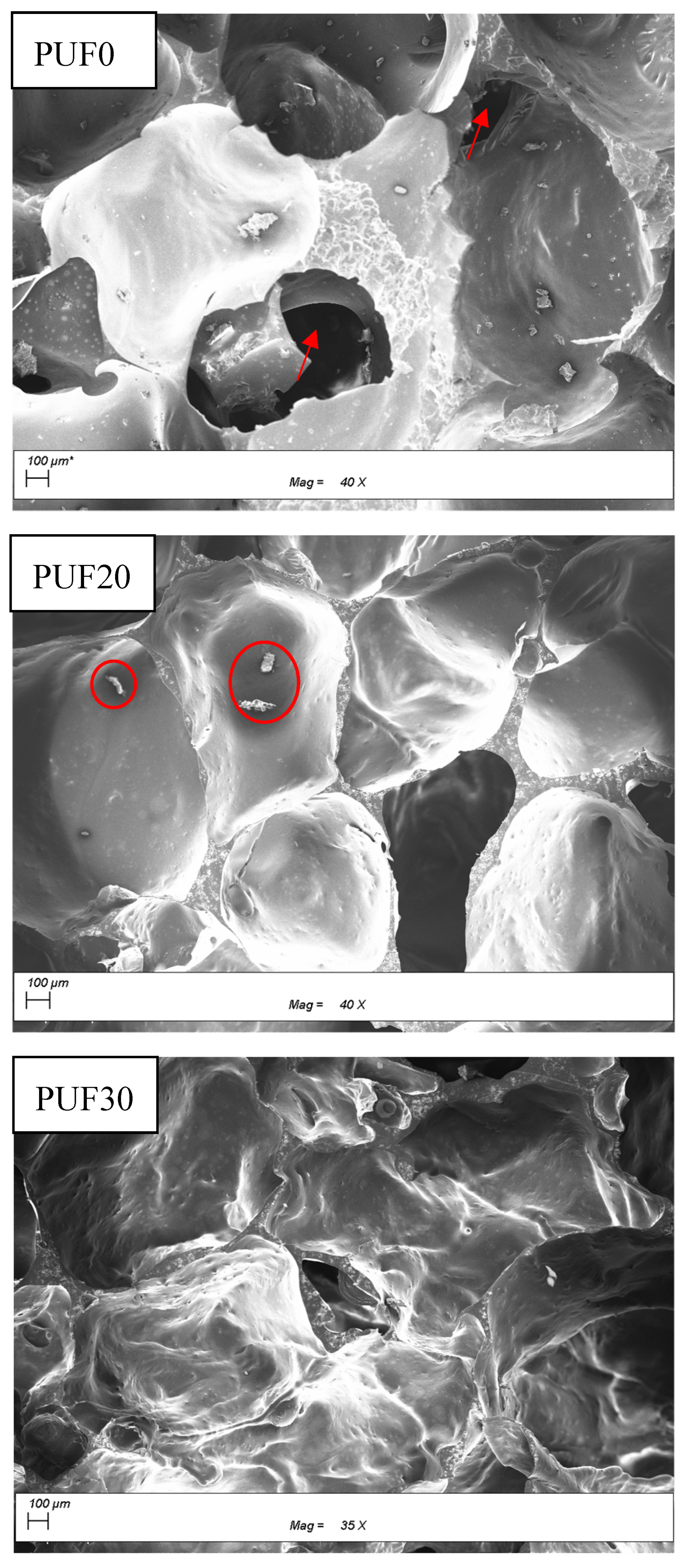
3.1. Microstructure of PUF

The mechanical strength of PUF was mainly ascribed to the closed-cells [37]. The defects on the closed-cells would greatly impair the mechanical performance of PUF. The closed cell content and cell size are listed in Table 2. The SEM images of PUF modified with different amount of CNF are shown in Figure 1. The PUF control consisted of larger closed cells than those modified with CNF (741 µm versus 634 and 589 µm). In addition, there were a few defects (red arrows in Figure 1) of the cells in PUF control. It is well known that rigid PUF is made of closed-cell [38], and the closed cell content is associated with thermal insulating performance [39]. The replacement of PEG400 with CNF resulted in closed-cells with smaller size and fewer defects. The introduction of CNF increased the medium viscosity, which hindered the cells’ coalescence and expansion [40]. In addition, due to its high strength, the introduction of CNF also imparted a resistance during the foaming process, which impeded the cell expansion and rendered smaller cells. Smaller closed cell size in CNF modified PUF indicated a higher amount of cells in a given mass, resulting in more homogeneous load distribution in the foam and greater mechanical strength [38]. At the replacement ratio of 20%, there was only a few CNF deposited on the closed-cells (red circles in Figure 1), while further increasing the replacement ratio to 30%, a large amount of CNF entangled and encompassed the closed-cells, acting as a reinforcing layer. The double-layer structure could contribute to an increase of mechanical strength to the composite due to the synergistic effect of CNF shell and PUF basic unit.

3.2. Fourier Transform Infrared Spectroscopy (FT-IR)

The FTIR spectra for both CNF and PUF are shown in Figure 2. Compared to PUF, CNF had a broader hydroxyl peak at 3300–3600 cm−1 [13], which consisted of mainly hydrogen-bonded hydroxyl groups, with a few free hydroxyl groups. On the other hand, All the PUF foams had a free hydroxyl peak at 3550 cm−1, while the one at 3300 cm−1 disappeared or was overlapped by the urethane -NH peak, which was a characteristic peak for PUF foam. This confirms the fact that the hydroxyl groups in CNF had successfully reacted with isocyanate, forming characteristic urethane carbonyl group at 1720 cm−1, -NH bending vibration at 1524 cm−1, and C-N bond at 1240 cm−1, respectively [41,42,43]. Interestingly, the characteristic isocyanate peak at 2275 cm−1 was not observed in all PUF foams, since the amount of PAPI27 was overdosed in the initial experiment design. The reason was that the environment’s moisture consumed part of the isocyanate group due to its strong reactivity towards H2O. The peaks at 1510 and 1596 cm−1 corresponded to the vibration bands of aromatic rings originating from PAPI27 [44]. The successful linkage of hydroxyl group in CNF to the PUF matrix was expected to endow the composite with promising mechanical properties.

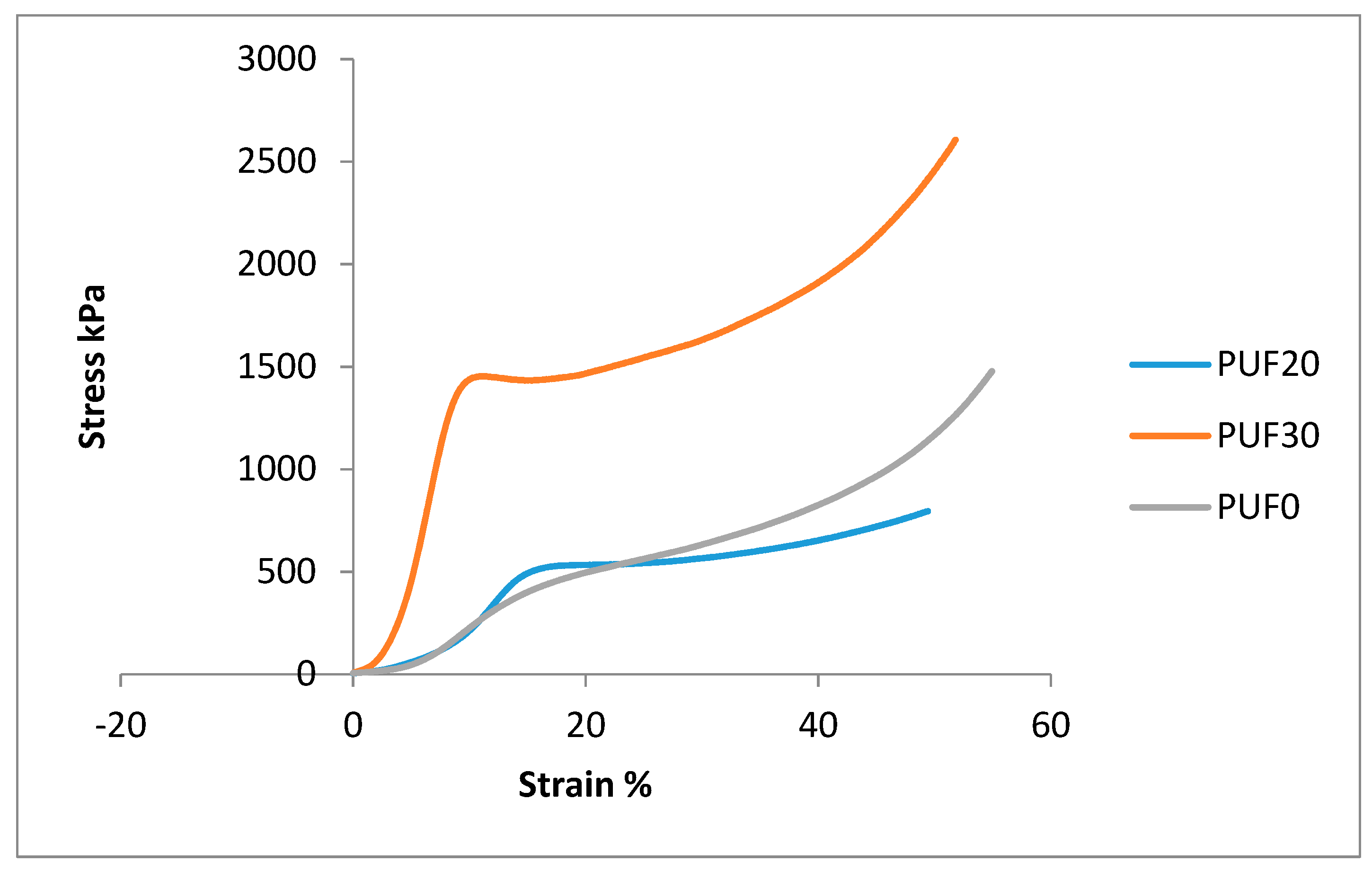
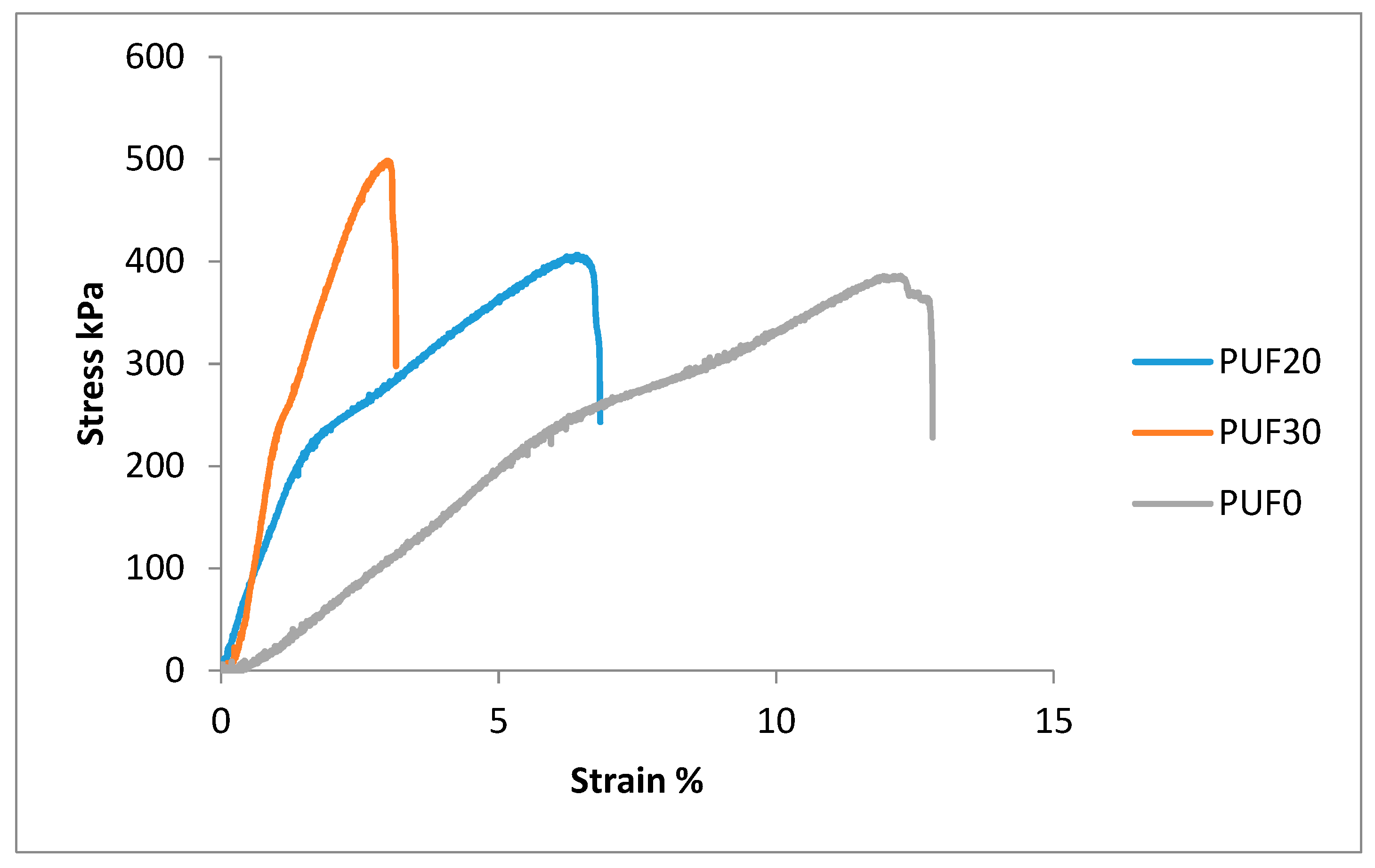
3.3. Mechanical Properties of PUF

Mechanical properties are among the most important parameters for SIP. The mechanical properties of foams are affected by many factors, including foam density, types of polyols and isocyanate used, ratio of −NCO/−OH, etc. [45,46,47,48]. In this study, the type of polyols and isocyanate was the same for all groups. In addition, the ratio of −NCO/−OH was set at 1.1. In order to diminish the effect of density, specific mechanical properties were evaluated, which are listed in Table 3. Partial replacement of petroleum-based polyols with CNF significantly improved the bending, compression, and tensile performance. The more CNF was used, the higher mechanical properties were achieved. PEG-400 was selected as the petroleum-based polyol in this study, which mainly contains of primary hydroxyl groups. These primary hydroxyl groups mainly react to form longer chains while fewer branches. In contrast, CNF contains massive secondary hydroxyl groups, contributing to the crosslinking reaction and forming highly rigid foam structure [45]. Therefore, more CNF created higher crosslinking density [45,49]. Higher hydroxyl functionality of CNF than that of PEG-400 enhanced the formation of allophanate crosslinks and urea linkages (hard segments), making the CNF modified PUF more difficult to compress. In addition, as mentioned in the microstructure section, more closed-cells were generated due to the introduction of CNF and higher resistance pressure against external compression force was created. The smaller closed-cell size and double-layer like structure of CNF modified PUF also contributed to greater mechanical strength due to more uniform load distribution.
Figure 3 shows the compressive stress-strain curves for PUF0 and CNF modified PUF. The PUF0 barely had a yield point, indicating an elastic performance. Replacing PEG-400 with 20% CNF significantly changed the foam performance into a stiffer phase, and the yield point showed up at 16% strain. Further increase the CNF replacement ratio to 30% resulted in a yield point at 10% strain, indicating a much stiffer phase. Our previous report stated that the CNF modified PUF had smaller cell size than the PUF0 [13]. Compared with using PEG-400 as the only polyol, the addition of CNF significantly increased the viscosity of part B suspension. Therefore, the possibility for the coalescence among the bubbles was reduced, resulting in the formation of foams with more cells as well as smaller cell size. Foams with smaller cell sizes usually had stronger cell walls, and foams with more cells could undertake higher external load [47,49]. In addition, smaller cells had less room to collapse. One other reason might be that excessive CNF filled in the cell gaps and shared partial load that contributed to higher compression strength.
Figure 4 shows the tensile stress–strain relation of PUF0 and CNF modified PUF. The tensile strength showed the same trend as the compressive strength. Due to steric hinderance effect, some of the secondary hydroxyl groups in CNF were not accessible to isocyanate groups. Those hydroxyl groups formed hydrogen bonds and contributed to the tensile strength. In addition, the long molecular chain of CNF facilitated the formation of macromolecules with a higher degree of orientation, thus improving the tensile strength [50].
According to technical data for SIP, the bending modulus of PUF composite produced in this work achieved the standard requirement [51]. Compared to the PUF fabricated by Wiyono et al., the one synthesized in this study had a lower compressive strength and modulus while having a higher tensile modulus [52]. The reason was that, in Wiyono’s work, commercial components were used, which were sophisticated and underwent massive experimental studies and verifications. In future work, improved formulation with better catalyst, surfactant, and polyols would be generated by our group to produce PUF with improved mechanical properties comparable to commercial counterparts.

3.4. Thermal Conductivity of PUF and CNF-PUF

The thermal conductivity of PUF0 and CNF modified PUF is listed in Table 2. Compared to the conventional value of commercial PUF (0.023–0.030 W/mK), the one without addition of CNF had a higher thermal conductivity due to defective cells and cell morphology [34,36,37,53,54]. However, introducing CNF into the PUF significantly reduced thermal conductivity to commercially required range, although slightly higher than those produced with modified bio-based polyols [40,55]. The thermal conductivity (λ) of a foam is comprised of the gas convection, gas conductivity, solid conductivity, and radiant heat transfer, as expressed in Equation (4) [56], of which the gas conductivity accounts for up to 80% of the total heat transfer, and the gas convection, solid conductivity, and radiant heat transfer only account for 20% [37,56,57]. The gas conductivity is illustrated in Wassiljewa Equation (Equation (5)), where y i is the molar fraction of the specific gas, λ i is the thermal conductivity of the specific gas, and A i j is the coefficients in Lindsay–Bromley equation. The PUF control contained more defective cells, which were filled by air, instead of carbon dioxide. As the carbon dioxide has a much lower thermal conductivity than air (0.018 versus 0.028 W·m−1·K−1), the gas conductivity of PUF0 was greatly influenced by the defective cells. The solid conductivity is described in Equation (6), where λ P U   p o l y m e r is the conductivity of solid PU polymer from crushed PUF, f s is the fraction of solid in strut, and δ is the volume fraction of voids, which is determined by Equation (7), where ρ f and ρ s stand for the density of PUF and PU polymer, respectively [56]. Since the density of PUF0 was slightly higher than that of CNF modified PUF, the volume fraction of voids of PUF0 was lower, and more solids were in the foam, indicating a higher solid conductivity of PUF0. Another impact on the thermal conductivity of PUF is from heat radiation, as determined by the Rosseland Equation (Equation (8)) [37,56], where σ is the Stephan Boltzman constant (5.7 × 10⁻⁸), T is the temperature, and K is the extinction coefficient, expressed by Equation (9), where d is the cell diameter, and Kw is the extinction coefficient of cell wall material. It was confirmed that the decrease of cell size in the CNF modified PUF had a stronger influence on the extinction coefficient than the decrease of the volume fraction of the solid did. So according to Equation (9), the overall extinction coefficient was increased, resulting in a decrease in radiation conductivity. It is well known that the thermal properties of rigid foam are ascribed to the closed cell content, the morphology, and the entrapped gases [58]. As mentioned above, the introduction of CNF generated smaller and stronger cells, which was beneficial during the foaming process, since it was less prone to form defective cells. Consequently, the thermal insulating performance was improved [55]. Moreover, the introduction of CNF rendered more cell walls within the foam structure, to some extent impeding the thermal radiation [47].
λ t o t a l = λ g a s + λ c o n v e c t i o n + λ s o l i d + λ r a d i a t i o n
λ g a s = i = 1 n y i × λ i j = 1 n y i × A i j
λ s o l i d = 1 3 λ P U   p o l y m e r × f s × ( 1 δ ) + 2 3 λ P U   p o l y m e r × ( 1 f s ) × ( 1 δ )
δ = 1 ρ f ρ s
λ r a d i a t i o n = 16 × σ × T 3 3 × K
K = 4.1 × f s × ρ f ρ s d + [ ( 1 f s ) × ρ f ρ s ] × K w

4. Conclusions

CNF modified PUF has shown great potential as a structural insulated material in wood construction industry. The introduction of CNF affected the foam microstructure from two aspects: firstly, the addition of spray-dried CNF increased the precursor viscosity and hindered the cells coalescence. In addition, the intrinsic high strength of CNF imparted an extra resistant force against cells expansion during the foaming process and formed smaller cells and reduced the chance of creating defective cells. The massive secondary hydroxyl groups located in CNF backbone facilitated the crosslinking reaction and formed strong rigid foam structure. Moreover, the smaller closed cell size in CNF modified PUF rendered more homogeneous load distribution in the foam, and larger amount of closed cells provided higher resistant pressure against external force and led to greater mechanical strength. Consequently, the mechanical performance of the foam was significantly improved by introducing CNF into the PUF matrix. The thermal conductivity of PUF composite was mainly influenced by the closed cell size and closed cell content. The introduction of CNF not only created smaller closed cells with fewer defects which filled with comparably low thermal conductive carbon dioxide, but also generated more cell walls, imposing more obstacles against heat transfer.

Author Contributions

W.L. contributed to the overall process of the experiment design, characterization, data analysis, and the manuscript drafting. B.P. supervised the whole project, reviewed the draft, and made comments.

Funding

The APC was funded by the College of Materials Science and Engineering, Nanjing Forestry University.

Acknowledgments

The authors would like to acknowledge the financial support by NJFU start-up funding (163020128).

Conflicts of Interest

The authors declare no conflict of interest.

References

  1. Meng, Q.; Chen, W.; Hao, H. Numerical and experimental study of steel wire mesh and basalt fibre mesh strengthened structural insulated panel against projectile impact. Adv. Struct. Eng. 2018, 21, 1183–1196. [Google Scholar] [CrossRef]
  2. Chen, W.; Hao, H.; Chen, S.; Hernandez, F. Performance of composite structural insulated panel with metal skin subjected to blast loading. Mater. Des. 2015, 84, 194–203. [Google Scholar] [CrossRef]
  3. Kayello, A.; Ge, H.; Athienitis, A.; Rao, J. Experimental study of thermal and airtightness performance of structural insulated panel joints in cold climates. Build. Environ. 2017, 115, 345–357. [Google Scholar] [CrossRef]
  4. Purasinghe, R.; Dusicka, P.; Garth, J.S.; Dedek, G.; Lum, H. In-plane cyclic behavior of structural insulated panel wood walls including slit steel connectors. Eng. Struct. 2018, 174, 178–197. [Google Scholar] [CrossRef]
  5. Polymer Foams Market Forecast to 2019| Smithers Rapra. Available online: https://www.smithersrapra.com/news/2014/may/polymer-foam-market-to-consume-25-3-million-tonnes (accessed on 14 February 2019).
  6. Efstathiou, K. Synthesis and Characterization of a Polyurethane Prepolymer for the Development of a Novel Acrylate-Based Polymer Foam; Budapest University of Technology and Economics (BME): Budapest, Hungary, 2011. [Google Scholar]
  7. Szycher, M. Szycher’s Handbook of Polyurethanes, 2nd ed.; CRC Press: Boca Raton, FL, USA, 2012; ISBN 9780439839584. [Google Scholar]
  8. Seydibeyoglu, M.O.; Misra, M.; Mohanty, A.; Blaker, J.J.; Lee, K.-Y.; Bismarck, A.; Kazemizadeh, M. Green polyurethane nanocomposites from soy polyol and bacterial cellulose. J. Mater. Sci. 2013, 48, 2167–2175. [Google Scholar] [CrossRef]
  9. Yang, J.; Li, Z.; Du, Q. An Experimental Study on Material and Structural Properties of Structural Insulated Panels (SIPs). Appl. Mech. Mater. 2011, 147, 127–131. [Google Scholar] [CrossRef]
  10. Zhou, X.; Sain, M.M.; Oksman, K. Semi-rigid biopolyurethane foams based on palm-oil polyol and reinforced with cellulose nanocrystals. Compos. Part Appl. Sci. Manuf. 2016, 83, 56–62. [Google Scholar] [CrossRef]
  11. Narine, S.S.; Kong, X.; Bouzidi, L.; Sporns, P. Physical Properties of Polyurethanes Produced from Polyols from Seed Oils: II. Foams. J. Am. Oil Chem. Soc. 2007, 84, 65–72. [Google Scholar] [CrossRef]
  12. Petrović, Z.S. Polyurethanes from Vegetable Oils. Polym. Rev. 2008, 48, 109–155. [Google Scholar] [CrossRef]
  13. Leng, W.; Li, J.; Cai, Z. Synthesis and Characterization of Cellulose Nanofibril-Reinforced Polyurethane Foam. Polymers 2017, 9, 597. [Google Scholar] [CrossRef]
  14. Chen, W.; Yu, H.; Li, Q.; Liu, Y.; Li, J. Ultralight and highly flexible aerogels with long cellulose I nanofibers. Soft Matter 2011, 7, 10360. [Google Scholar] [CrossRef]
  15. Klemm, D.; Heublein, B.; Fink, H.-P.; Bohn, A. Cellulose: Fascinating biopolymer and sustainable raw material. Angew. Chem. Int. Ed. 2005, 44, 3358–3393. [Google Scholar] [CrossRef] [PubMed]
  16. Liu, Q.; Jing, S.; Wang, S.; Zhuo, H.; Zhong, L.; Peng, X.; Sun, R. Flexible nanocomposites with ultrahigh specific areal capacitance and tunable properties based on a cellulose derived nanofiber-carbon sheet framework coated with polyaniline. J. Mater. Chem. A 2016, 4, 13352–13362. [Google Scholar] [CrossRef]
  17. Silva, T.C.F.; Habibi, Y.; Colodette, J.L.; Elder, T.; Lucia, L.A. A fundamental investigation of the microarchitecture and mechanical properties of tempo-oxidized nanofibrillated cellulose (NFC)-based aerogels. Cellulose 2012, 19, 1945–1956. [Google Scholar] [CrossRef]
  18. Zanini, M.; Lavoratti, A.; Lazzari, L.K.; Galiotto, D.; Pagnocelli, M.; Baldasso, C.; Zattera, A.J. Producing aerogels from silanized cellulose nanofiber suspension. Cellulose 2017, 24, 769–779. [Google Scholar] [CrossRef]
  19. Zhao, J.; Zhang, X.; He, X.; Xiao, M.; Zhang, W.; Lu, C. A super biosorbent from dendrimer poly(amidoamine)-grafted cellulose nanofibril aerogels for effective removal of Cr(vi). J. Mater. Chem. A 2015, 3, 14703–14711. [Google Scholar] [CrossRef]
  20. Chen, W.; Yu, H.; Liu, Y.; Chen, P.; Zhang, M.; Hai, Y. Individualization of cellulose nanofibers from wood using high-intensity ultrasonication combined with chemical pretreatments. Carbohydr. Polym. 2011, 83, 1804–1811. [Google Scholar] [CrossRef]
  21. Barari, B.; Ellingham, T.K.; Ghamhia, I.I.; Pillai, K.M.; El-Hajjar, R.; Turng, L.-S.; Sabo, R. Mechanical characterization of scalable cellulose nano-fiber based composites made using liquid composite molding process. Compos. Part B Eng. 2016, 84, 277–284. [Google Scholar] [CrossRef]
  22. Chen, B.; Zheng, Q.; Zhu, J.; Li, J.; Cai, Z.; Chen, L.; Gong, S. Mechanically strong fully biobased anisotropic cellulose aerogels. RSC Adv. 2016, 6, 96518–96526. [Google Scholar] [CrossRef]
  23. Chen, W.; Li, Q.; Wang, Y.; Yi, X.; Zeng, J.; Yu, H.; Liu, Y.; Li, J. Comparative Study of Aerogels Obtained from Differently Prepared Nanocellulose Fibers. ChemSusChem 2014, 7, 154–161. [Google Scholar] [CrossRef] [PubMed]
  24. Meng, Y.; Young, T.M.; Liu, P.; Contescu, C.I.; Huang, B.; Wang, S. Ultralight carbon aerogel from nanocellulose as a highly selective oil absorption material. Cellulose 2015, 22, 435–447. [Google Scholar] [CrossRef]
  25. Meng, Y.; Wang, X.; Wu, Z.; Wang, S.; Young, T.M. Optimization of cellulose nanofibrils carbon aerogel fabrication using response surface methodology. Eur. Polym. J. 2015, 73, 137–148. [Google Scholar] [CrossRef] [Green Version]
  26. Olsson, R.T.; Azizi Samir, M.A.S.; Salazar-Alvarez, G.; Belova, L.; Ström, V.; Berglund, L.A.; Ikkala, O.; Nogués, J.; Gedde, U.W. Making flexible magnetic aerogels and stiff magnetic nanopaper using cellulose nanofibrils as templates. Nat. Nanotechnol. 2010, 5, 584–588. [Google Scholar] [CrossRef] [PubMed]
  27. Wang, M.; Anoshkin, I.V.; Nasibulin, A.G.; Ras, R.H.A.; Nonappa, N.; Laine, J.; Kauppinen, E.I.; Ikkala, O. Electrical behaviour of native cellulose nanofibril/carbon nanotube hybrid aerogels under cyclic compression. RSC Adv. 2016, 6, 89051–89056. [Google Scholar] [CrossRef] [PubMed] [Green Version]
  28. Zhai, T.; Zheng, Q.; Cai, Z.; Turng, L.-S.; Xia, H.; Gong, S. Poly(vinyl alcohol)/Cellulose Nanofibril Hybrid Aerogels with an Aligned Microtubular Porous Structure and Their Composites with Polydimethylsiloxane. ACS Appl. Mater. Interfaces 2015, 7, 7436–7444. [Google Scholar] [CrossRef] [PubMed]
  29. Sharmin, E.; Zafar, F. Polyurethane: An Introduction. In Polyurethane; Zafar, F., Ed.; InTech: Rijeka, Croatia, 2012; ISBN 978-953-51-0726-2. [Google Scholar] [Green Version]
  30. Li, Y.; Ragauskas, A.J. Cellulose nano whiskers as a reinforcing filler in polyurethanes. Algae 2011, 75, 10–15. [Google Scholar]
  31. Xu, X.; Liu, F.; Jiang, L.; Zhu, J.Y.; Haagenson, D.; Wiesenborn, D.P. Cellulose Nanocrystals vs. Cellulose Nanofibrils: A Comparative Study on Their Microstructures and Effects as Polymer Reinforcing Agents. ACS Appl. Mater. Interfaces 2013, 5, 2999–3009. [Google Scholar] [CrossRef] [PubMed]
  32. Srithep, Y.; Turng, L.-S.; Sabo, R.; Clemons, C. Nanofibrillated cellulose (NFC) reinforced polyvinyl alcohol (PVOH) nanocomposites: Properties, solubility of carbon dioxide, and foaming. Cellulose 2012, 19, 1209–1223. [Google Scholar] [CrossRef]
  33. Li, Y.; Ren, H.; Ragauskas, A.J. Rigid polyurethane foam reinforced with cellulose whiskers: Synthesis and characterization. Nano-Micro Lett. 2010, 2, 89–94. [Google Scholar] [CrossRef] [Green Version]
  34. Santiago-Calvo, M.; Tirado-Mediavilla, J.; Rauhe, J.C.; Jensen, L.R.; Ruiz-Herrero, J.L.; Villafañe, F.; Rodríguez-Pérez, M.Á. Evaluation of the thermal conductivity and mechanical properties of water blown polyurethane rigid foams reinforced with carbon nanofibers. Eur. Polym. J. 2018, 108, 98–106. [Google Scholar] [CrossRef]
  35. Fu, J.; He, C.; Huang, J.; Chen, Z.; Wang, S. Cellulose nanofibril reinforced silica aerogels: Optimization of the preparation process evaluated by a response surface methodology. RSC Adv. 2016, 6, 100326–100333. [Google Scholar] [CrossRef]
  36. Gama, N.; Ferreira, A.; Barros-Timmons, A. Polyurethane Foams: Past, Present, and Future. Materials 2018, 11, 1841. [Google Scholar] [CrossRef] [PubMed]
  37. Furtwengler, P.; Matadi Boumbimba, R.; Sarbu, A.; Avérous, L. Novel Rigid Polyisocyanurate Foams from Synthesized Biobased Polyester Polyol with Enhanced Properties. ACS Sustain. Chem. Eng. 2018, 6, 6577–6589. [Google Scholar] [CrossRef]
  38. Mariappan, T.; Khastgir, D.; Singha, N.; Manjunath, B.S.; Naik, Y.P. Mechanical, Morphological and Thermal Properties of Rigid Polyurethane Foam: Effect of the Fillers. Cell. Polym. 2007, 26, 245–259. [Google Scholar]
  39. Hejna, A.; Kirpluks, M.; Kosmela, P.; Cabulis, U.; Haponiuk, J.; Piszczyk, Ł. The influence of crude glycerol and castor oil-based polyol on the structure and performance of rigid polyurethane-polyisocyanurate foams. Ind. Crops Prod. 2017, 95, 113–125. [Google Scholar] [CrossRef]
  40. Tan, S.; Abraham, T.; Ference, D.; Macosko, C.W. Rigid polyurethane foams from a soybean oil-based Polyol. Polymer 2011, 52, 2840–2846. [Google Scholar] [CrossRef]
  41. Strankowski, M.; Włodarczyk, D.; Piszczyk, Ł.; Strankowska, J. Polyurethane Nanocomposites Containing Reduced Graphene Oxide, FTIR, Raman, and XRD Studies. J. Spectrosc. 2016, 2016, 1–6. [Google Scholar] [CrossRef]
  42. Szymanska-Chargot, M.; Zdunek, A. Use of FT-IR Spectra and PCA to the Bulk Characterization of Cell Wall Residues of Fruits and Vegetables Along a Fraction Process. Food Biophys. 2013, 8, 29–42. [Google Scholar] [CrossRef] [PubMed]
  43. Zhang, C.; Ren, Z.; Yin, Z.; Qian, H.; Ma, D. Amide II and Amide III Bands in Polyurethane Model Soft and Hard Segments. Polym. Bull. 2008, 60, 97–101. [Google Scholar] [CrossRef]
  44. Huang, X.; De Hoop, C.F.; Xie, J.; Wu, Q.; Boldor, D.; Qi, J. High bio-content polyurethane (PU) foam made from bio-polyol and cellulose nanocrystals (CNCs) via microwave liquefaction. Mater. Des. 2018, 138, 11–20. [Google Scholar] [CrossRef]
  45. Yusuf, A.K.; Mamza, P.A.P.; Ahmed, A.S.; Agunwa, U. Physico-Mechanical Properties of Rigid Polyurethane Foams Synthesized From Modified Castor Oil Polyols. Int. J. Sci. Res. Publ. 2016, 6, 9. [Google Scholar]
  46. Ali, E.S.; Zubir, S.A. The Mechanical Properties of Medium Density Rigid Polyurethane Biofoam. MATEC Web Conf. 2016, 39, 01009. [Google Scholar] [CrossRef] [Green Version]
  47. Ugarte, L.; Gómez-Fernández, S.; Peña-Rodríuez, C.; Prociak, A.; Corcuera, M.A.; Eceiza, A. Tailoring Mechanical Properties of Rigid Polyurethane Foams by Sorbitol and Corn Derived Biopolyol Mixtures. ACS Sustain. Chem. Eng. 2015, 3, 3382–3387. [Google Scholar] [CrossRef]
  48. Goods, S.H.; Neuschwanger, C.L.; Whinnery, L.L. Mechanical Properties of a Structural Polyurethane Foam and the Effect of Particulate Loading. MRS Proc. 1998, 521. [Google Scholar] [CrossRef] [Green Version]
  49. Fan, H.; Tekeei, A.; Suppes, G.J.; Hsieh, F.-H. Properties of Biobased Rigid Polyurethane Foams Reinforced with Fillers: Microspheres and Nanoclay. Int. J. Polym. Sci. 2012, 2012, 1–8. [Google Scholar] [CrossRef]
  50. Stirna, U.; Beverte, I.; Yakushin, V.; Cabulis, U. Mechanical properties of rigid polyurethane foams at room and cryogenic temperatures. J. Cell. Plast. 2011, 47, 337–355. [Google Scholar] [CrossRef]
  51. Technical Data for Structural Insulated Panels | Foard Panel. Available online: https://www.foardpanel.com/technical-data/ (accessed on 13 February 2019).
  52. Wiyono, P.; Suprobo, P.; Kristijanto, H. Characterization of physical and mechanical properties of rigid polyurethane foam. ARPN J. Eng. Appl. Sci. 2016, 11, 8. [Google Scholar]
  53. Kirpluks, M.; Cabulis, U.; Zeltins, V.; Stiebra, L.; Avots, A. Rigid Polyurethane Foam Thermal Insulation Protected with Mineral Intumescent Mat. Autex Res. J. 2014, 14. [Google Scholar] [CrossRef]
  54. Wu, J.-W.; Sung, W.-F.; Chu, H.-S. Thermal conductivity of polyurethane foams. Int. J. Heat Mass Transf. 1999, 42, 2211–2217. [Google Scholar] [CrossRef]
  55. Beltrán, A.A.; Boyacá, L.A. Production of rigid polyurethane foams from soy-based polyols. Lat. Am. Appl. Res. 2011, 41, 75–80. [Google Scholar]
  56. Jarfelt, U.; Ramnäs, O. Thermal conductivity of polyurethane foam Best performance. In Proceedings of the 10th International Symposium on District Heating and Cooling, Hannover, Germany, 3–5 September 2006; pp. 1–12. [Google Scholar]
  57. Traeger, R.K. Physical Properties of Rigid Polyurethane Foams. J. Cell. Plast. 1967, 3, 405–418. [Google Scholar] [CrossRef] [Green Version]
  58. Fleurent, H.; Thijs, S. The Use of Pentanes as Blowing Agent in Rigid Polyurethane Foam. J. Cell. Plast. 1995, 31, 580–599. [Google Scholar] [CrossRef]
Figure 1. Scanning electron microscopy (SEM) images of PUF modified with different amount of CNF (0–30%).
Forests 10 00200 g001
Figure 2. FTIR spectra of CNF and PUF.
Forests 10 00200 g002
Figure 3. Compressive stress–strain relation for PUF.
Forests 10 00200 g003
Figure 4. Tensile stress–strain relation for PUF.
Forests 10 00200 g004
Table 1. Foaming formulation.
ChemicalsParts by Weight (Pbw)Equivalent Weight (Eq.wt.) Role
PUF0PUF20PUF30
PEG-4001008070198Polyol
Spray-dried CNF02030186Polyol, reinforcing agent
DABCO T123330Catalyst
DABCO DC5357111100Surfactant
Deionized water0.80.80.89Blowing agent
PAPITM 27888990133Reactive prepolymer
Table 2. Foam structure and physical properties.
Sample IDDensityClosed Cell ContentMean Cell SizeThermal Conductivity
g/cm3%µmW/mK
PUF00.059 ± 0.000989.1 ± 1.01741 ± 980.04390 ± 0.0015
PUF200.050 ± 0.000891.2 ± 0.63634 ± 790.03014 ± 0.00089
PUF300.051 ± 0.001191.9 ± 0.54589 ± 730.02724 ± 0.00087
Table 3. Specific mechanical properties of PUF.
Sample IDSpecific Bending ModulusSpecific Bending StrengthSpecific Compression ModulusSpecific Compression StrengthSpecific Tensile ModulusSpecific Tensile Strength
Gpa*cm3/gMPa*cm3/gMPa*cm3/gMPa*cm3/gMPa*cm3/gMPa*cm3/g
PUF09.38 ± 0.95103.07 ± 4.4411.90 ± 0.991.52 ± 0.1012.62 ± 0.571.41 ± 0.089
PUF2018.95 ± 0.88177.38 ± 6.3037.05 ± 1.353.67 ± 0.1829.14 ± 1.191.62 ± 0.073
PUF3034.95 ± 0.93319.00 ± 10.3751.25 ± 0.584.55 ± 0.14127.31 ± 3.813.4 ± 0.072

