1. Introduction
Because of changing resource conditions, plantation forests are expected to replace natural forests as the main source of timber in the near future. Japanese cedar (
Cryptomeria japonica (L. f.) D. Don) is one of the main plantation species in Taiwan and Japan. Attributing to its fast-growing cycle and favorable processing properties, the processed Japanese cedar products are often used for structural and decorative applications. Based on government information, the plantation area of Japanese cedar in Taiwan is approximately 30,555 ha and the total stock volume is approximately 7.69 million m
3 [
1], which could be a great resource of domestic timber supply. On the other hand, proper forest landscape restoration activities such as afforestation and reforestation of planted forests and woodlots would be beneficial for CO
2 sequestration efficiency [
2]. Consequently, it is important to study the potential use for Japanese cedar plantation wood in future applications.
However, plantation wood often has a medium or small diameter, and the proportion of juvenile wood is higher than that of natural forests, thereby limiting direct structural application. Csoka et al. [
3] mentioned that the lumber obtained from young Japanese cedar contains a high percentage of juvenile wood, which is unfavorable in structural applications. Therefore, engineered products using plantation wood for structural applications should be developed to solve the shortage of high-diameter timber. Glued wood products such as glued-laminated beams constructed using plantation wood have been studied using different species and types of wood adhesives. However, few studies have investigated the use of plantation wood for built-up structural components.
Built-up timber beams can be assembled in different cross-sectional shapes; the I-shape is the most commonly adopted and features three components, namely two flanges on the top and bottom and a web component in the middle. The advantages of built-up beams include high strength, high stiffness, and light weight; moreover, built-up beams using metal connectors for assembly require shorter processing time than conventional glued-laminated beams or glued I-beams because of the long curing time required for wood adhesives [
4,
5,
6,
7]. More importantly, built-up beams can be produced with different configurations as per requirement.
In contrast to adhesives, metal connectors such as nails and screws used for assembling built-up beams can be highly efficient and time-saving because the curing time for adhesives is not required. Because metal connectors are mainly responsible for connecting the wood members of the built-up beam, the specifications of the metal connectors and their connection capacity with wood should be carefully considered. Studies have revealed that the diameters of connectors exhibit a linear relationship with withdrawal resistance [
8,
9,
10,
11] and that the screw-withdrawal resistance is usually higher than the nail-withdrawal resistance [
11]. Furthermore, previous research has indicated that adding glue when using metal connectors to assemble built-up beams can improve their flexural mechanical performance [
12]. In particular, resorcinol formaldehyde resin can result in high bonding strength and increase the shear resistance capacity [
13,
14].
In addition to wood I-beams, flanges can substantially enhance the flexural rigidity, and the type and size of flange influence the flexural load-bearing capacity [
15,
16,
17,
18,
19,
20,
21,
22,
23]. The depth of the web of wood I-beams affects the flexural load-bearing capacity, but the width of the web does not considerably influence the flexural rigidity [
24,
25,
26,
27,
28]. Moreover, the length of the flanges or web can be increased by finger jointing [
29,
30,
31].
In this study, Japanese cedar (Cryptomeria japonica (L. f.) D. Don) harvested from a plantation forest in Taiwan was used to develop built-up beams using self-tapping screws as connectors to assemble components based on various assembly configurations. The effects of these configurations on the flexural performance and failure modes were investigated.
2. Materials and Methods
Japanese cedar (
Cryptomeria japonica (L. f.) D. Don) lumber was harvested in Hsinchu, Taiwan, the tree age measured approximately 35 years old, and processed by Jang Chang Lumber Industry Ltd., Taiwan. Before processing, the lumber was oven-dried and conditioned to approximately 15% moisture content, and the overall average density of the lumber was 452 ± 53 kg/m
3. Processed lumber dimensions for the flanges were 38 × 140 × 3300 mm
3 and those for the web were 38 × 89 × 3300 mm
3. Furthermore, the lumbers were stress-graded based on Chinese National Standard (CNS)-14630. The nominal grade of E50 implies 4 GPa ≤ flexural modulus of elasticity < 6 GPa; E70 implies 6 GPa ≤ flexural modulus of elasticity < 8 GPa; E90 implies 8 GPa ≤ flexural modulus of elasticity < 10 GPa; and E110 implies 10 GPa ≤ flexural modulus of elasticity < 12 GPa. Moreover, self-tapping screws were selected and purchased from Rothoblaas®, Cortaccia, BZ, Italy; their specifications are shown in
Figure 1.
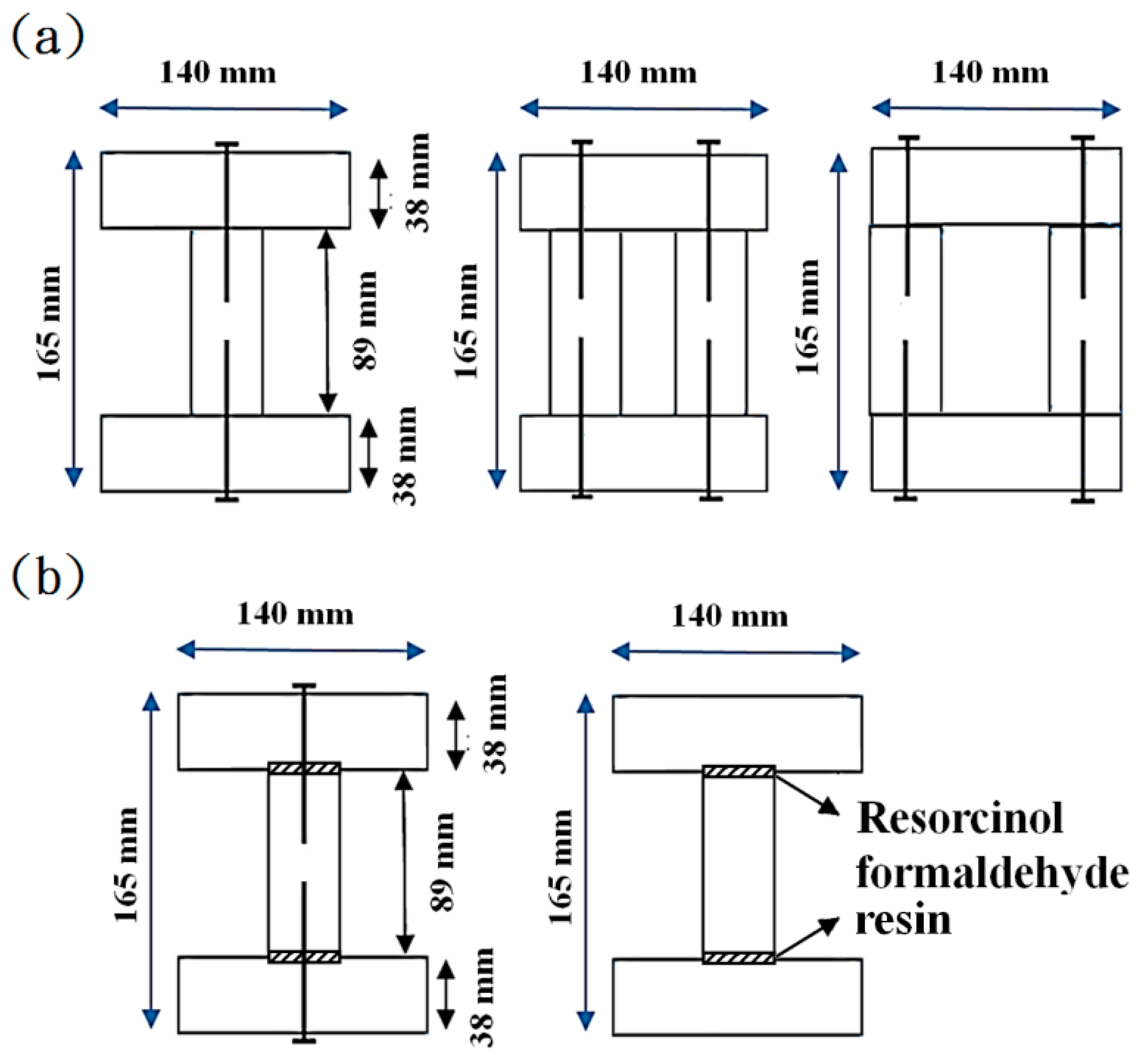
To study the effects of factors such as cross sections and component grades on the flexural capacity, the
Cryptomeria japonica built-up beams were assembled using lumbers of different grades, and the cross sections are illustrated in
Figure 2a. Moreover, to enhance the bonding between flanges and the web, as well as for comparison with the conventional glue-bonding method, two types of built-up beams were produced as shown in
Figure 2b.
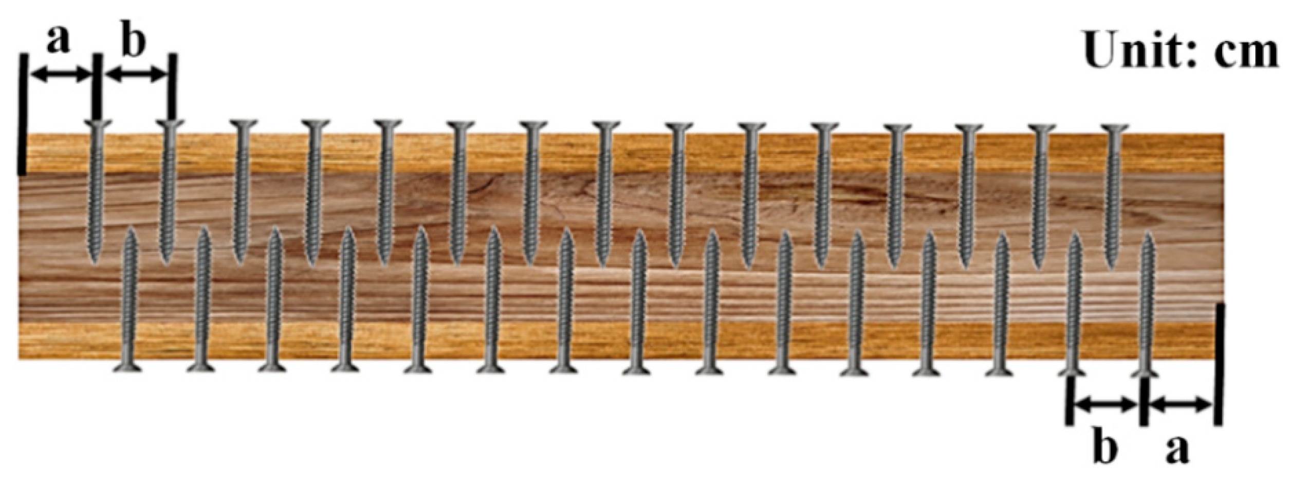
The side views of the configurations of the built-up beams are shown in
Figure 3. The distance of edge “a” was at least 20 cm, and various spacing “b” values (20–60 cm) were applied between the screws to study the effect of spacing on the flexural performance of the built-up beams. In
Table 1, the group code represents different configurations with respect to the cross-sectional shape (I-, II-, and box-beam), top flange grade, web grade, and bottom flange grade, assembly method (S represents self-tapping screws and G represents glued), and the distance between screws.
To compare the built-up beams with conventional glued-laminated timber (glulam) beams, E90 Cryptomeria japonica lumber and resorcinol formaldehyde resin (RF, pH = 8.6, viscosity = 1296 mPa*s, Wood Glue Industrial Co., Ltd., Tainan, Taiwan) were employed to fabricate built-up beams with glue and 4-layer glued-laminated beams as a reference. The resin to curing agent weight ratio was 100:15; the spread amount was 250 g/m2 and the pressing time was 1 day.
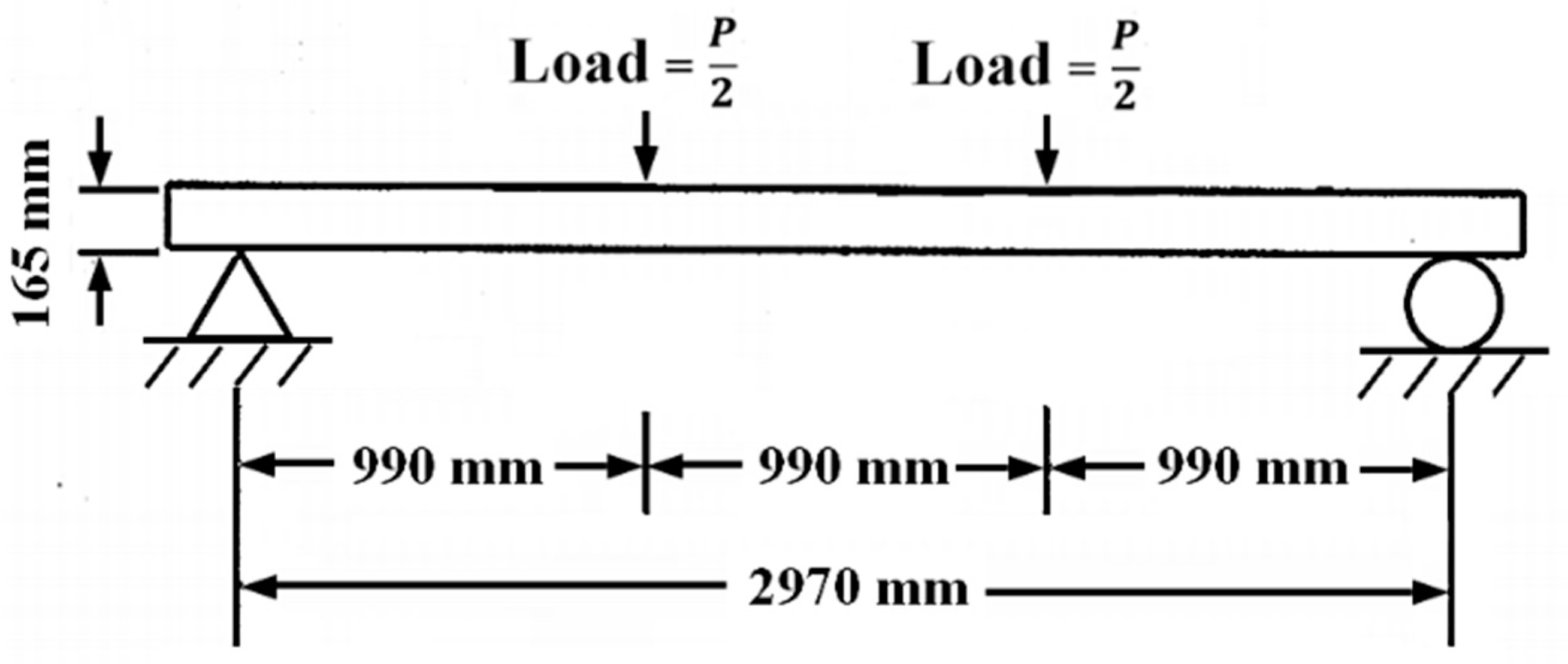
For the flexural test, based on the CNS 11031, a 4-point bending configuration was adopted, and the loading scheme is shown in
Figure 4. The indoor ambient testing environment was approximately 23–25 °C and 65%–70% RH, controlled by an air conditioner, and moisture contents of beams were measured before tests using a moisture meter (BD-2100, Delmhorst Instrument Co., Towaco, NJ, USA). On the basis of the load-deflection curve of the built-up beams, the coefficient K, indicating the initial rigidity, was be determined by passing a linear straight line through 0.1 × maximum flexural load (P
max) and 0.4 × P
max (Equation (1)). The elastic deflection was expected to be 0.1 × P
max to 0.4 × P
max, and the modulus of elasticity (MOE) was calculated as shown in Equation (2).
where
K = initial stiffness (N/mm),
L = Length of the beam (mm),
E = Modulus of elasticity (N/mm
2),
I = Moment of inertia (mm
4),
P = Load on the beam (N), Δ = Deflection (mm),
a =
L/3 (mm).
Moreover, the modulus of rupture (MOR), which indicates the bending strength of the built-up beam, can be calculated using Equation (3).
where
= Bending strength (N/mm
2),
M = Bending moment (N·mm) based on Equation 4,
y = Distance of the center of the cross section to the surface of the flange (mm),
I = Moment of inertia (mm
4),
P = Maximum load (N),
L = Span of the bending test (mm),
a =
L/3 (mm).
3. Results and Discussion
The overall average moisture contents of the flange and the web were 13.5% and 13.8%, respectively, measured before flexural tests.
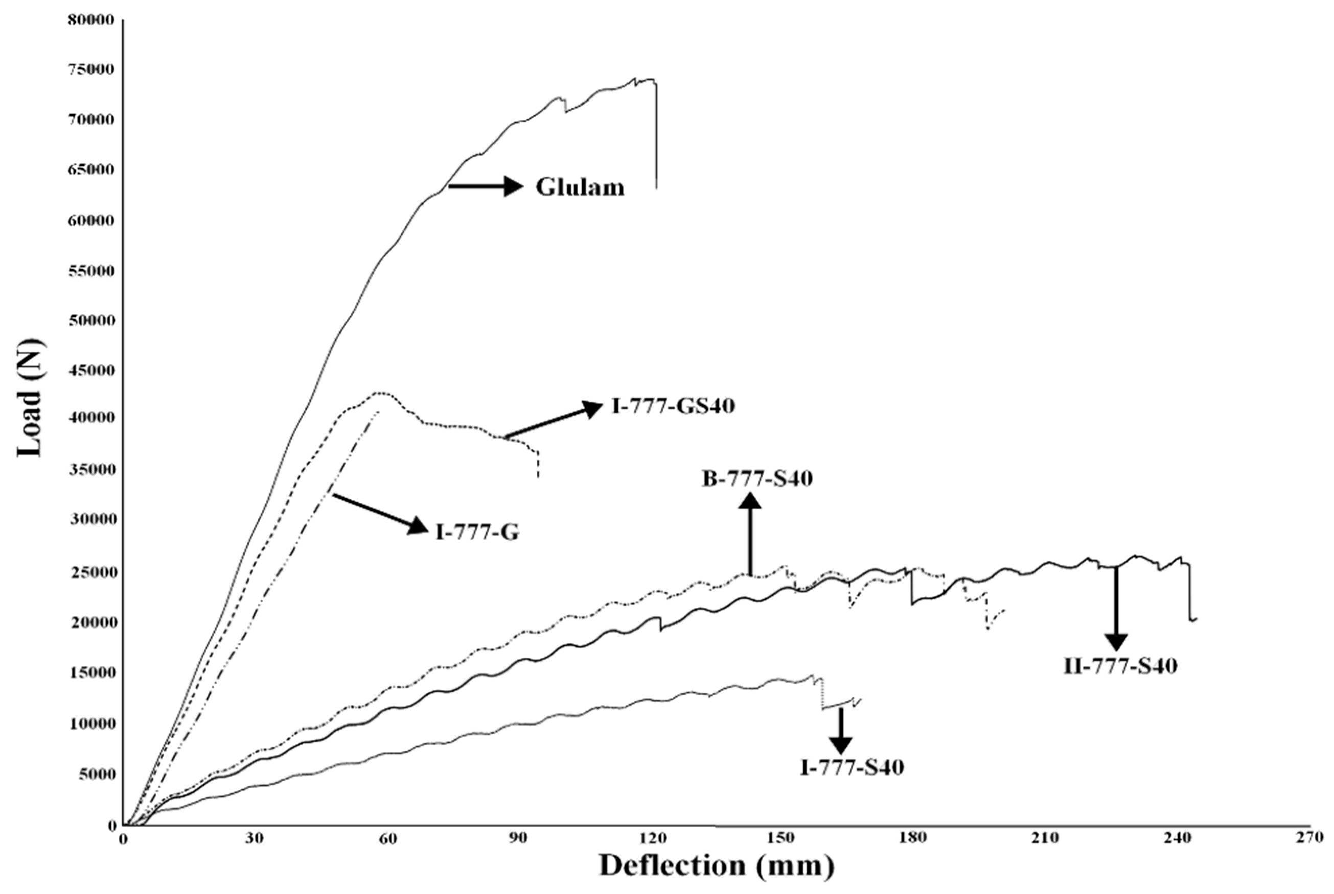
Figure 5 shows the representative load-displacement curves of various groups. The results show that beams using glue exhibited approximately linear behavior, whereas those using only screws exhibited some undulating and stepwise responses, implying that shear force between the flanges and the web may cause buckling, as well as the dislocation of the self-tapping screws because of crushing failure of the wood body at the screw penetration locations. In general, groups in which glue was added exhibited higher load-bearing capacity, whereas groups that used only self-tapping screws revealed high ductility, enduring larger deflection before failure.
Furthermore, different load-displacement responses among the glued-I beams (e.g., I-777-G), glued-screwed-I beams (e.g., I-777-GS40) and glulam beams were observed. The results indicated that the glued-I beam and the glulam beam exhibited a brittle failure mode, initiating the direct collapse of the beams after reaching maximum load; however, the glued-screwed-I beam exhibited ductility after reaching the maximum load and maintained a level of load resistance capacity, although a stepwise decrement was also observed. These observations imply that the high bending rigidity may be attributed to glue; however, the self-tapping screws may enhance the ductility of the built-up beams, preventing a sudden collapse of the structure in practical applications.
The results of the flexural performance of each group are shown in
Table 2. Comparing I-777-S40, II-777-S40, and B-777-S40 revealed a substantial improvement in the flexural load-bearing capacity by adding another web component (e.g., II-beam and box-beam). Moreover, adding another web member improved the flexural rigidity and bending strength. However, because there was no significant difference between II-777-S40 and B-777-S40 with respect to various properties, the locations of the web components may not considerably influence the flexural load-bearing capacity and performance.
Moreover, for the same grade of flange, using a lower grade of web (I-4410-S40) resulted in a marginally lower average maximum flexural load, flexural rigidity, and strength compared with a higher-grade web (I-4610-S40), although no significant difference was observed between these two groups. Furthermore, for web components of similar grades but flanges of different grades, I-959-S40 resulted in a significantly higher maximum flexural load-bearing capacity, flexural rigidity, and strength than I-565-S40, implying that a higher grade of flange played a key role in improving the flexural capacity and mechanical performance of the built-up beams, which was in agreement with some previous studies [
6,
15,
16,
18,
20,
21,
22]. Nevertheless, comparisons between I-959-S40 and I-559-S40 revealed no significant difference in the maximum flexural load, flexural rigidity, and strength, although an improvement in the flexural performance owing to the use of a higher-grade top flange was observed, indicating that the grade of the top flange may not considerably affect the flexural capacity and mechanical performance.
In addition, comparing the groups that featured different spacing between the screws suggested that this may influence the flexural performance of the built-up beams. In general, increasing the spacing resulted in a lower maximum flexural load-bearing capacity, flexural rigidity, and strength. When the spacing between the screws was as low as 20 cm, the maximum flexural load-bearing capacity and flexural strength were comparable with those of the II-beam and box-beam with 40 cm spacing between the screws. In addition, the results implied that for further fabrication of the built-up beams, adopting a spacing of 30–60 cm between the screws may produce beams of similar flexural load-bearing capacity, which would influence the selection of the number of screws used in production, thereby affecting the production cost.
The effect of adding RF resin and self-tapping screws together was investigated by comparing I-777-G and I-777-GS40. The results showed no significant improvement in the maximum flexural load and strength by adding screws for the glued group; however, a significant increase in the flexural rigidity for I-777-GS40 was observed, suggesting that the self-tapping screws may be applied as a reinforcement to enhance the flexural rigidity for conventional glued products in practical use.
To use built-up beams in structural applications, weak spots and failure modes should be carefully considered and evaluated. In this study, a 4-point bending mode was used, and the span-to-depth ratio was 18, suggesting long beam flexural behavior. Moreover, failure modes of the built-up beams were discussed based on ASTM D5055 (2008) [
32]. The shear resistance of the built-up beams resulted from the connections between the flanges and the web. The stress distribution of the screwed built-up beams may be unlike that of typical homogeneous beams, and the performance of the connection featured slippage between the members due to horizontal shear. Consequently, the resistance to the horizontal shear of built-up beams relies mainly on the flexural rigidity of the self-tapping screws responsible for the bonding between the flanges and the web, as well as withdrawal resistance between the self-tapping screws and the wood.
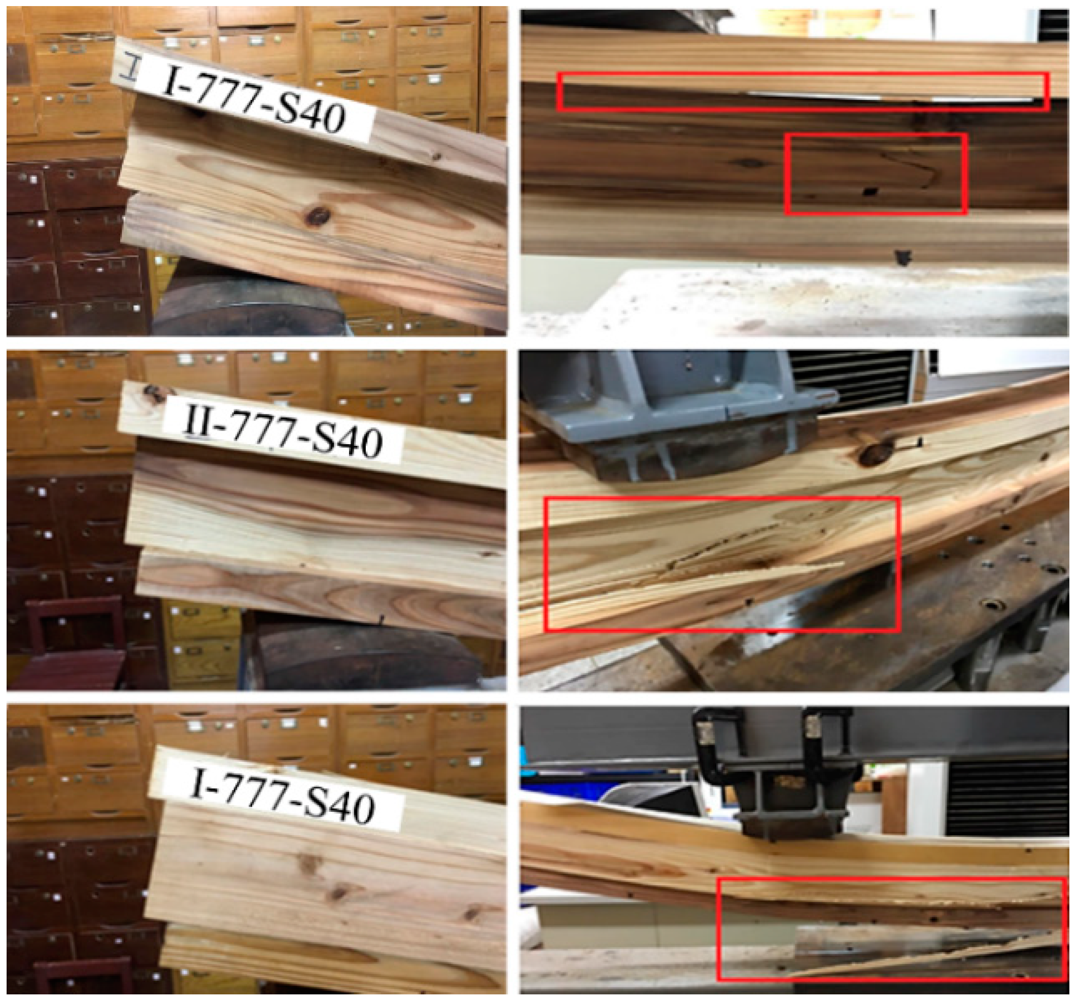
In general, failures on the web and bottom flange were observed under the loading positions (
Figure 6), which was in accordance with flange failure under tension and indicated typical bending failure of long-span flexural members.
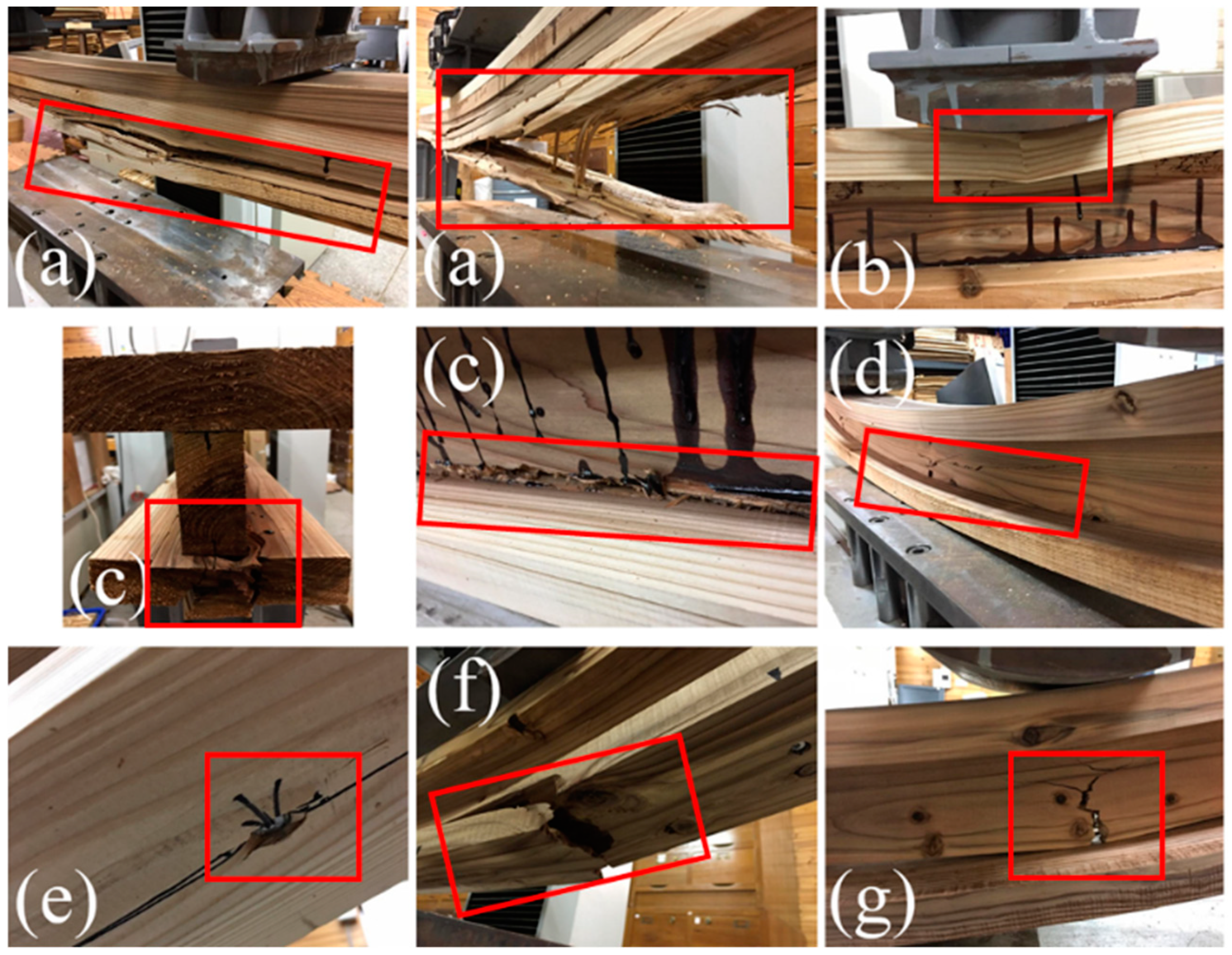
Figure 7 presents the common failure modes of the developed built-up beams. The failures usually resulted from the locations of the self-tapping screws and natural defects such as knots. Moreover, the failure locations were sometimes observed at the web, particularly at the position of the screws, indicating wood crushing failures caused by side compression from the self-tapping screws. Cracks then propagated along the wood grain, eventually resulting in web failure. Johnson et al. [
33] also mentioned the failures would begin near the position of metal fasteners in flanges of wood I-beams. Occasionally, surface compression failure was observed at the loading positions on the top flanges. For the glued built-up beams and the glulam beams, the failure locations were usually observed at the natural defects of lumber due to stress concentration, which initiated from wood and propagated along the wood grain. Furthermore, tension failures at the bottom flange were typical cases for glued built-up beams and glulam. On the other hand, web buckling used to be of major concern for wood I-beams [
34]; however, in this study, thick lumber webs were used so that no typical web buckling was observed.
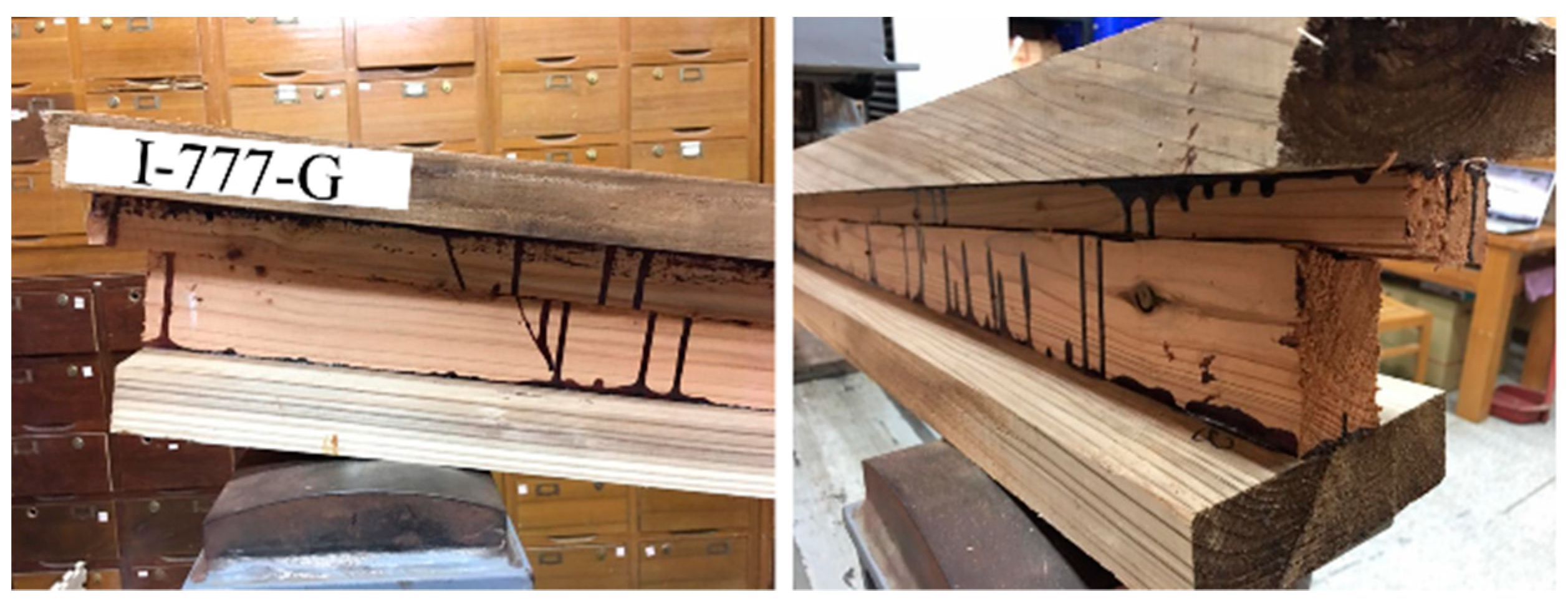
Horizontal shear failure in the web at the edge of the beams can be found in the built-up I-beams, as shown in
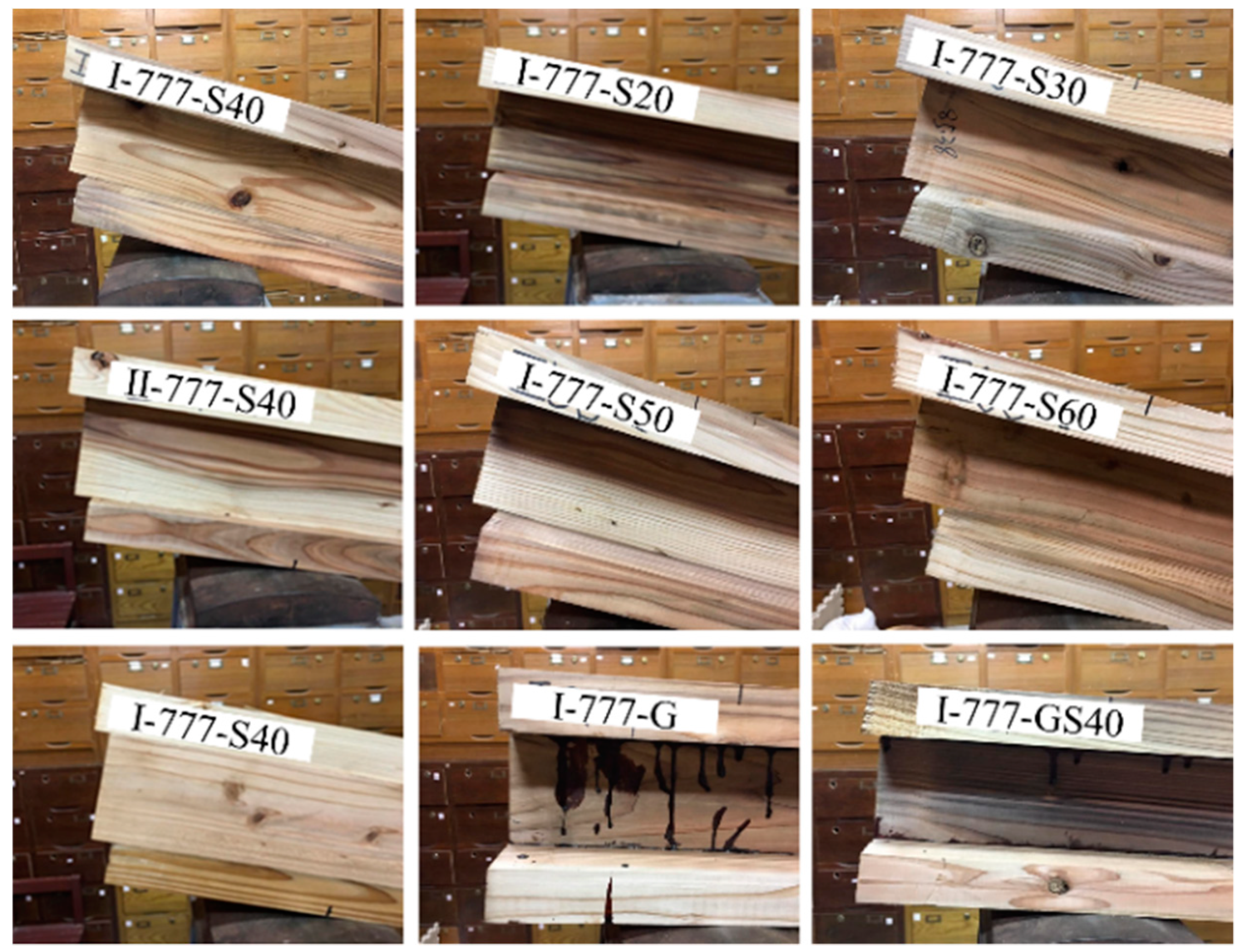
Figure 8. In addition, slippage between the flanges and the web can be commonly observed in the screwed built-up beams (
Figure 9); furthermore, a longer spacing between the self-tapping screws resulted in more noticeable slippage between the flanges and the web. The slippage between the flange and web may resulted from incomplete interaction between the flange and web and should be carefully considered in design [
15]. However, adding glue improved the slippage resistance capacity by enhancing the bonding between the flanges and web. Some previous studies also concluded that metal fastener-glued built-up beams showed greater mechanical performance than those using either metal fasteners or glue [
34,
35]. In particular, when the screw position was close to the beam edge, deep penetration into the flange due to surface crushing by the screws was observed. Owing to horizontal shear force, self-tapping screws may be withdrawn; however, because self-tapping screws exhibit a high grip on wood, surface crushing on flanges can be observed.
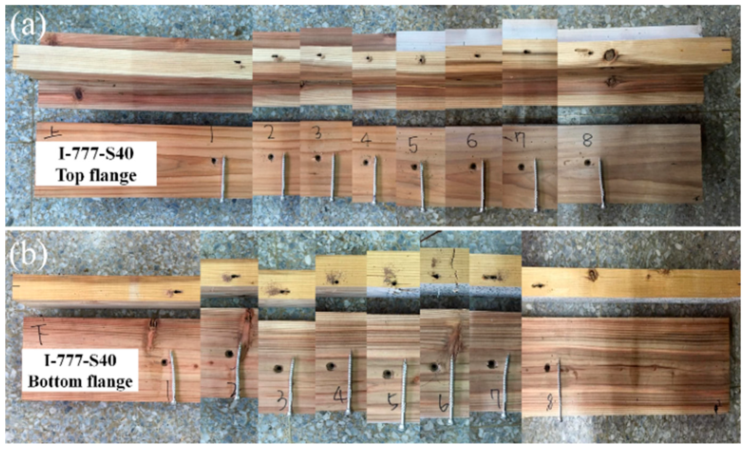
In addition,
Figure 10 displays disassembled built-up beams, showing the representative results of distortion deformation of the screws used for assembling beams, indicating that screws used on the bottom flanges caused more severe deformation than those used on the top flanges because of higher shear stress between the bottom flange and web than that between the top flange and the web. Moreover, increasing the spacing between the screws caused more apparent deformations. Nevertheless, because adding glue improved the horizontal shear resistance, smaller deformations were observed on screws used in groups with glue, and the surface crushing on the flanges was not severe.
4. Conclusions
In this study, built-up beams were developed using Japanese cedar (Cryptomeria japonica (L. f.) D. Don) and self-tapping screws, and the effects of different assembly configurations on the flexural load-bearing capacity and failure modes of the products were investigated. Results showed that adding glue provided flexural rigidity, whereas using self-tapping screws resulted in built-up beams with high ductility but relatively low flexural bearing capacity. However, enhancing the flexural ductility is important for practical applications.
When using components of similar grades, adding more web components can improve the performance; however, the location of the web components may not significantly influence the results. Furthermore, the grades of the web have negligible effect on the flexural load-bearing capacity, whereas the grades of the flanges have substantial influence on the flexural load-bearing capacity. In addition, a smaller spacing between the screws improves the flexural load-bearing performance, but also causes cracks in wooden components.
Typical bending failure modes were observed in the built-up beams, indicating tension failure on the bottom flange and slippage between the flanges and the web due to horizontal shear, which also caused buckling deformation in the screws. On the other hand, horizontal shear failure in the web at the edge of the beams can be found in the built-up I-beams, particularly when longer spacing between the self-tapping screws was applied, and adding glue would improve the horizontal shear resistance. As well, surface failure on flanges due to compression and wood crushing failures at webs caused by side compression from the self-tapping screws and could also be found. Moreover, failures commonly result from natural defects on the bottom flange or the place on the bottom flange directly below the loading position.


