Article

An Intelligent Fuzzy Third-Order Sliding Mode Strategy for Energy Management of DFIG-Based Wind Energy Systems

1
Environment Laboratory, Electromechanical Department, Mining Institute, University Larbi Tebessi, Tebessa 12002, Algeria
2
Department of Electrical Engineering, Faculty of Technology, Hassiba Benbouali University of Chlef, Chlef 02000, Algeria
3
Electrical Department, University Badji Mokhtar of Annaba, Annaba 23000, Algeria
4
Laboratory of Materials Physics, Radiation and Nanostructures (LPMRN), Bordj Bou-Arteridj 34030, Algeria
5
Department of Electrical Engineering, University Batna-2, Batna 05078, Algeria
6
Pitești University Centre, The National University of Science and Technology POLITEHNICA Bucharest, 110040 Pitesti, Romania
*
Author to whom correspondence should be addressed.
Algorithms 2026, 19(7), 590; https://doi.org/10.3390/a19070590
Submission received: 26 May 2026 / Revised: 11 July 2026 / Accepted: 13 July 2026 / Published: 16 July 2026

Abstract

The doubly fed induction generator (DFIG) has become one of the most widely adopted technologies in modern wind energy conversion systems due to its high efficiency, flexible operation, and capability to operate under variable wind-speed conditions. Nevertheless, maintaining high power quality, reducing harmonic distortion, and ensuring reliable operation under parameter uncertainties and grid disturbances remain major challenges. Conventional proportional–integral (PI)-based control approaches often suffer from limited robustness and sensitivity to system nonlinearities, which can adversely affect the dynamic performance and operational stability of wind energy systems. To address these limitations, this paper proposes an advanced hybrid control strategy based on the integration of fuzzy logic (FL) and a third-order sliding mode controller (TOSMC) for the control of DFIG-based wind turbines. The proposed FL–TOSMC combines the robustness and fast convergence properties of sliding mode control with the adaptive capability of fuzzy logic, thereby reducing dependence on accurate mathematical models and enhancing tolerance to parameter variations and external disturbances. The developed controller is applied to maximum power point tracking (MPPT) and direct field-oriented control of the DFIG to maximize energy extraction and ensure stable power regulation. The simulation results obtained in the MATLAB/Simulink (2021) environment demonstrate that the proposed strategy improves the dynamic response of the system by reducing overshoot, accelerating error convergence, minimizing steady-state oscillations, and decreasing total harmonic distortion compared with the conventional TOSMC approach. Furthermore, the proposed controller provides enhanced tracking performance, improved robustness against parameter uncertainties, and better power-quality characteristics under various operating conditions. These results indicate that the FL–TOSMC approach is an effective control solution for improving the operational performance of DFIG-based wind energy conversion systems.

1. Introduction

Wind energy (WE) has become one of the fastest-growing renewable energy sources owing to its sustainability, environmental benefits, and ability to satisfy the increasing global demand for electrical power (EP). Wind turbines (WTs) convert the kinetic energy of the wind into mechanical power, which is subsequently transformed into electrical energy through electrical generators [1]. Compared with conventional fossil-fuel-based generation, WE contributes to reducing greenhouse gas emissions, lowering energy production costs, and improving energy independence, particularly in countries with limited fossil resources [2,3]. Among WT technologies, horizontal-axis wind turbines (HAWTs) are the most widely deployed because of their superior aerodynamic efficiency and higher power generation capability compared with vertical-axis wind turbines (VAWTs) [4,5,6].
To further increase energy capture, multi-rotor WT (MRWT) technology has recently attracted considerable attention. Instead of relying on a single large rotor, MRWT systems integrate multiple rotors within the same structure, leading to improved energy extraction, enhanced operational stability, and better performance under severe wind conditions [7,8,9,10,11].
Among the various electrical generators employed in WE conversion systems (WECSs), the doubly fed induction generator (DFIG) remains the preferred solution because of its variable-speed operation, independent active and reactive power (Ps and Qs) control, reduced converter rating, low maintenance requirements, and relatively low implementation cost [12,13,14,15,16,17,18,19]. Nevertheless, DFIG-based WECSs still face important challenges, including power fluctuations, sensitivity to parameter variations, and deterioration of power quality (PQ), particularly under variable wind conditions.
Numerous control techniques have been proposed to improve the performance of DFIG-based systems, including direct torque control (DTC), synergetic control (SC), vector control (VC), backstepping control (BC), direct power control (DPC), field-oriented control (FOC), sliding mode control (SMC), and high-order SMC methods [20,21,22,23,24,25,26,27]. Among these approaches, FOC remains one of the most widely adopted owing to its simple implementation, fast dynamic response, and reliable decoupled control of Ps and Qs [28,29,30]. Depending on the rotor flux orientation strategy, FOC can be implemented as direct FOC (DFOC) or indirect FOC (IFOC), where DFOC offers a simpler structure with fewer controllers while maintaining satisfactory dynamic performance [31,32,33].
Despite these advantages, conventional DFOC based on proportional–integral (PI) controllers suffers from power ripples, limited robustness, and relatively high current total harmonic distortion (THD), especially under parameter uncertainties [34]. Consequently, considerable research has focused on enhancing DFOC performance through advanced modulation and intelligent control techniques. Several studies have combined DFOC with modified space vector modulation (MSVM), fuzzy logic (FL), neural networks (NNs), super-twisting control, model predictive control, and higher-level multilevel converters to improve PQ, reduce THD, and enhance robustness [35,36,37,38,39,40,41]. Although these methods significantly improve certain performance indices, they often increase computational complexity, require accurate mathematical models, depend on heuristic tuning procedures, or still exhibit considerable power ripples under disturbed operating conditions.
The third-order SMC (TOSMC) method has recently emerged as an attractive nonlinear control strategy because of its strong robustness, fast dynamic response, low control gain, and reduced dependence on the mathematical model of the controlled system [42,43,44,45]. Its application to DFIG-based WT and MRWT systems has demonstrated noticeable improvements in tracking performance, MPPT efficiency, ripple reduction, and current quality compared with conventional PI-based DFOC [44,46]. Nevertheless, previous investigations indicate that TOSMC performance may still degrade under parameter uncertainties and external disturbances, motivating the development of more adaptive control strategies [46,47].
Among intelligent techniques, the FL method has proven particularly suitable for renewable energy applications because of its model-free nature, robustness against uncertainties, and successful implementation in numerous WE control systems [48,49,50]. Motivated by these advantages, this paper proposes a hybrid FL–TOSMC to improve both MPPT and DFOC performance in DFIG-based WECSs. Unlike previously reported approaches [51,52], the proposed controller combines the adaptive capability of FL with the robustness of TOSMC to achieve superior tracking accuracy, enhanced disturbance rejection, reduced power and current ripples, and lower current THD without requiring an accurate mathematical model.
The main contributions of this work are summarized as follows:
  • Development of a novel FL–TOSMC controller for both MPPT and DFOC of DFIG-based WE systems.
  • Significant enhancement in MPPT efficiency under variable wind conditions.
  • Reduction in Ps/Qs and current ripples.
  • Improvement in system robustness against parameter variations and external disturbances.
  • Reduction in current THD and overshoot compared with the conventional TOSMC strategy.
The remainder of this paper is organized as follows: Section 2 presents the mathematical model of the proposed WECS. Section 3 describes the FL–TOSMC controller. Section 4 introduces the proposed MPPT strategy. Section 5 presents the DFOC–FL–TOSMC power control scheme. The simulation results under different wind profiles are discussed in Section 6, while Section 7 concludes this paper.

2. WE Conversion System Model

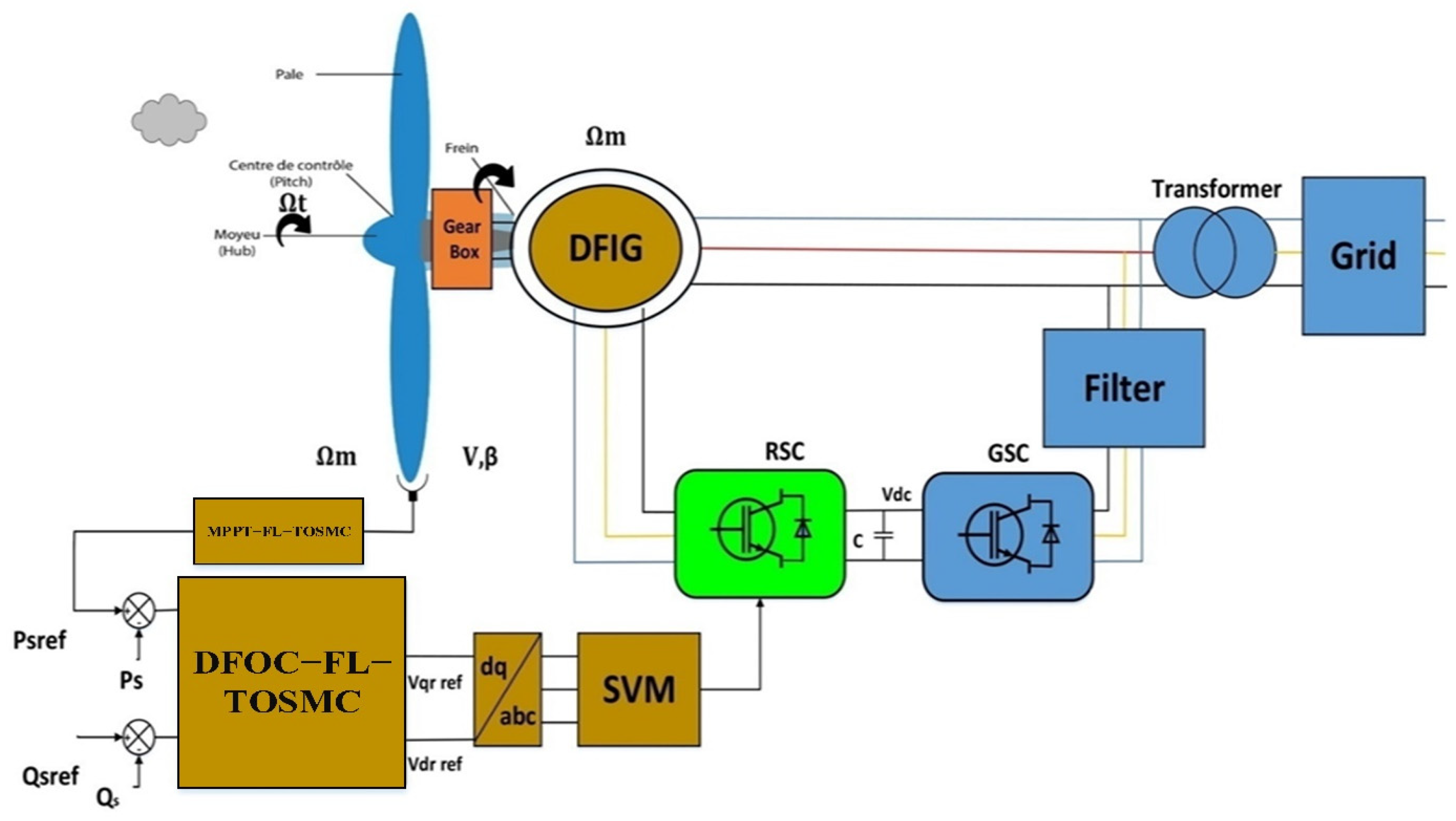
This section presents the mathematical model of the proposed DFIG-based WECS. Figure 1 illustrates the overall architecture and the interactions among its principal components. The system consists of a WT, a gearbox (when required), a DFIG, a back-to-back power converter including the rotor-side converter (RSC) and the grid-side converter (GSC), a DC-link capacitor, an MPPT unit, the proposed DFOC–FL–TOSMC controller, and the electrical grid.
The WT converts the kinetic energy of the wind into mechanical power, which is transmitted to the DFIG shaft through the gearbox to achieve the required operating speed. The DFIG converts this mechanical power into EP while enabling variable-speed operation and independent regulation of the stator Ps and Qs.
The RSC controls the rotor currents to regulate the electromagnetic torque and the exchanged Ps and Qs. Simultaneously, the GSC maintains the DC-link voltage at its reference value while ensuring stable power exchange with the utility grid. The DC-link capacitor acts as an intermediate energy storage element that enhances system stability during transient operating conditions.
To maximize the harvested WE, the MPPT algorithm continuously adjusts the operating point according to wind speed (WS) variations. In addition, the proposed DFOC–FL–TOSMC strategy combines FL adaptation with the third-order SMC method to achieve accurate decoupled power regulation, improved disturbance rejection, fast dynamic response, and enhanced robustness against parameter uncertainties. Finally, the generated EP is injected into the grid while satisfying synchronization and PQ requirements.

2.1. WT Model

In recent years, WTs have become one of the most effective technologies for converting WE into mechanical power for EP generation. Their widespread deployment has contributed to reducing greenhouse gas emissions and meeting the growing electricity demand. The power extracted from a WT mainly depends on WS and rotor dimensions, while the aerodynamic interaction between neighboring turbines in wind farms may reduce energy production if adequate spacing is not maintained. According to [53], the power available from the wind is expressed by Equation (1), which determines the mechanical power supplied to the generator for EP production.
p t = 1 2 ρ π R t 2 C p ( λ , β ) V 3
where ρ is the air density (kg/m3), R t is the blade radius of the wind turbine (m), V is the WS (m/s), and C p is the power coefficient, which is a non-linear function of the tip-speed ratio (λ) and the blade pitch angle (β).
The power extracted from a WT is strongly influenced by the power coefficient Cp(λ,β), which depends on the tip-speed ratio (TSR) and the blade pitch angle (β). According to [54], Cp is calculated using Equation (2).
C p λ , β = 0.0068 . λ + 0.5176 116 λ i 0.4 β 5 e 21 λ i
λi can be calculated using Equation (3).
1 λ i = 1 λ + 0.08 β 0.035 β 3 + 1
As indicated by Equation (2), the maximum Cp is achieved when the blade pitch angle is β = 0°. Moreover, Cp varies with the TSR, which depends on the WS and the turbine rotor dimensions. The TSR is calculated using Equation (4).
λ = Ω t × R t V
From Equation (1), the aerodynamic torque driving the generator can be determined. In WECSs, the turbine operates at a lower rotational speed but produces a higher torque than the generator due to the gearbox ratio. According to [54], the aerodynamic torque is calculated using Equation (5).
T a e r = p t Ω t = 1 2 C p λ , β ρ π R t 2 V 3 1 Ω t
Equation (6) represents the relationship between turbine torque and mechanical torque.
T m e c = T t G
The turbine speed differs from the generator speed, as a gearbox is used to regulate the speed. Equation (7) shows the relationship between the turbine speed ( Ω t ) and the generator speed ( Ω g ), and, using this equation, the turbine speed can be calculated. As is well known, the turbine speed is lower than the generator speed.
Ω t = Ω g G
According to [55], the relationship between the DFIG torque and the WT torque can be expressed by Equation (8). This equation is of great importance in power generation and DFIG operation. Depending on the value of the difference between the two torques, the DFIG can be operated as a generator or as a motor.
T t T e m = Ω g × f + J t o t d Ω g d t
where Tem is the electromagnetic torque of the DFIG and Tt is the turbine torque. The total inertia torque and the friction coefficient are represented by J and f, respectively.

2.2. DFIG Model

The second main component of the studied ES is the DFIG, which converts the mechanical power extracted from the wind into EP. Owing to its simple control, low cost, reduced maintenance requirements, and independent rotor-side control, the DFIG is widely adopted in variable-speed WECSs [11]. In addition, its stator is directly connected to the grid, eliminating the need for an intermediate interface and reducing system complexity and cost. The mathematical model (MM) of the DFIG has been extensively reported in the literature [9,17,21], where the Park transformation is commonly employed. According to [56], the DFIG model in the d–q reference frame is described by Equations (9)–(19). Equation (9) represents the stator and rotor voltage equations, relating the voltages to the corresponding currents and flux linkages.
V d s = R s i d s ω s φ q s + d φ d s d t V q s = ω s φ d s + R s i q s + d φ q s d t V d r = R r i d r + d φ d r d t ω r φ q r V q r = d φ q r d t + R r i q r + ω r φ d r
Equation (10) shows the stator/rotor flux of DFIG [57].
φ d s = M i d r + l s i d s φ q s = l s i q s + M l r i q r φ d r = M i d s + l r i d r φ q r = l r i q r + M i q s
The values of   V d s , V q s , V d r , and V q r on the d–q axes represent the stator and rotor voltages, respectively. The currents i d s , i q s , i d r , and i q r represent the stator and rotor currents, while φ d s , φ q s , φ d r , and φ q r represent the stator and rotor flux components. The resistances of the rotor and stator windings on the d q axes are represented by   R r and R s . Values L s , L r ,   and M denote the self-inductance of the stator, the self-inductance of the rotor and the mutual inductance between two coils, respectively, with   ω r = ω s p . Ω g .
The value of Qs and Ps for the stator of a generator can be calculated using currents and voltages according to Equation (11). This equation is used to estimate capabilities.
P s = 3 2 ( V q s i q s + V d s i d s ) Q s = 3 2 ( V d s i q s + V q s i d s )
The DFIG torque is largely related to the rotor. Rotor currents and flux can be used to calculate torque for DFIG. This torque can be calculated using Equation (12). To control and change the torque, it is sufficient to control the rotor currents.
T e m = 3 p M 2 l s φ d s i q r + φ q s i d r
Using the stator flux orientation technique and choosing a Park reference frame linked to the stator flux while neglecting the stator resistance ( R s ), we can obtain:
φ =   φ d s =   φ s et   φ q s = 0
Using Equation (13), the current and voltage can be written according to Equations (14) and (15).
v d s = 0 v q s = v s = ω s φ s
i d s = φ s l s M l s i d r i q s = M l s i q r
Additionally, the Ps and Qs equations can be expressed in terms of the rotor current components i d r and i q r by Equation (16).
P s = V s 3 M 2 l s i q r Q s = V s 3 M 2 l s i d r + 3 V s 2 2 l s ω s
Equation (17) can be used to represent the torque.
T e m = p 3 M 2 l s φ s i q r
The rotor voltage equations can be simplified by Equation (18).
V d r = σ l r d I d r d t R r i d r + σ l r ω r i q r V q r = σ l r d I q r d t + σ l r ω r i d r + R r i q r + ω r M L s φ s
Equation (19) represents the expression for σ used in Equation (18).
σ = 1 M 2 l r × L s
The power control of DFIG is commonly achieved using PI controllers due to their simple implementation and satisfactory dynamic response. However, their performance deteriorates under parameter variations, leading to poor PQ and increased current THD. To overcome these limitations, several advanced control techniques have been investigated, including nonlinear strategies such as SMC and BC, as well as intelligent methods based on PSO, FL, and NN approaches.

3. Description of the FL-TOSMC Approach

In this section, the proposed FL–TOSMC controller is introduced for DFIG power regulation. The proposed strategy combines the advantages of FL and TOSMC to enhance PQ and reduce current THD. Since the proposed approach is based on TOSMC, its main principles, advantages, and limitations are first presented.

3.1. TOSMC Technique

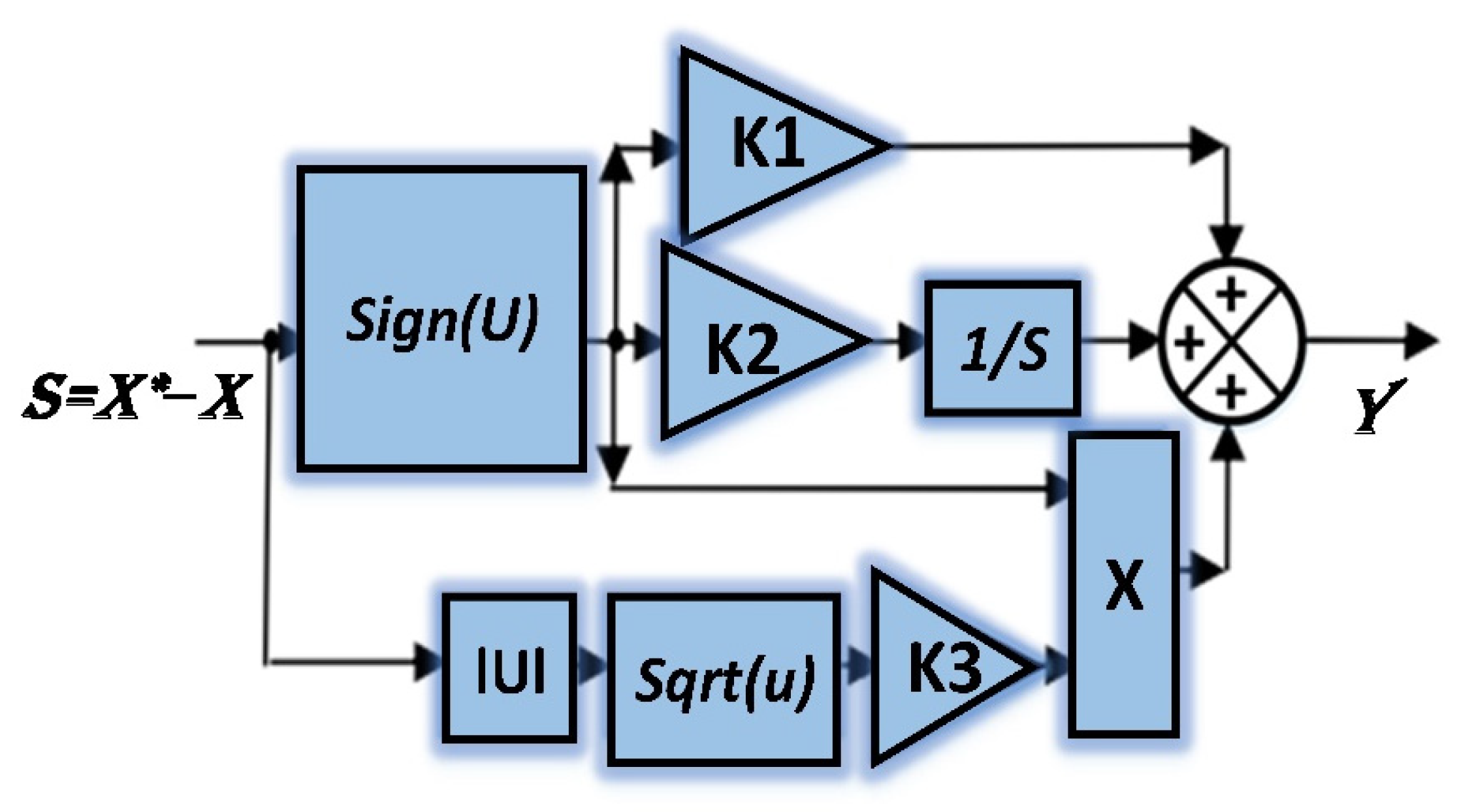
The TOSMC method is an advanced nonlinear control technique developed as an extension of second-order SMC, offering improved accuracy and robustness. In [58], TOSMC was applied to DFIG-based systems by replacing conventional controllers, demonstrating superior performance compared with PI controllers. However, sensitivity to parameter variations was still observed during robustness tests. According to [42], TOSMC is a modified version of the super-twisting controller, designed to improve tracking performance and robustness. The mathematical formulation of TOSMC has been presented in [42,43,44]. Unlike conventional model-based controllers, TOSMC does not require an accurate mathematical model of the system, which enhances its robustness against uncertainties. The sliding surface of the TOSMC approach is defined as given in Equation (20).
S X = X X
According to [42,44], the MM of the TOSMC technique can be expressed by Equation (21). From this equation, it is noted that the TOSMC technique is easy to apply to complex and simple systems, as it does not require complex calculations.
u ( t ) = k 1 × s i g n ( s ) + k 2 s i g n s d t   + k 3 s   × s i g n ( s )
To ensure optimal performance, the gains K1, K2, and K3 are chosen based on a proportional hierarchy of magnitude:
  • K 1 is sized to overcome the maximum boundaries of external disturbances.
  • K 2 is set to a higher order of magnitude to accelerate integral error elimination and smooth the sliding phase.
  • K 3 balances transient and steady-state tracking.
This proportional scaling allows the FL system to dynamically adapt the controller gains within smooth boundaries, significantly improving the DR and energy efficiency while reducing chattering.
Gain values for the TOSMC technique can be calculated using experimentation and simulation, or smart strategies such as genetic algorithms can be used.
To study the stability of the TOSMC approach, Lyapunov’s theory can be used. This theory relies on using Equation (22) to give the stability condition. However, using this theory requires calculations and the use of mathematical equations. Compared to Lyapunov’s theory, the Bode curve can be used to prove the stability of the TOSMC approach more easily. The Bode curve is a graphical method by which the stability of the TOSMC approach can be proven easily and without the need to perform complex calculations. The Bode curve method is based on the use of MATLAB, and results are obtained quickly.
S × S ˙ < 0
Figure 2 presents the structure of the proposed TOSMC, which adopts a single-input single-output configuration. The controller receives the tracking error, defined as the difference between the reference and measured variables, and generates the required control signal to regulate the system states. The design is based on a third-order sliding surface that uses the error and its higher-order derivatives to improve convergence and robustness. Compared with conventional SMC methods, TOSMC reduces chattering while maintaining robustness against parameter uncertainties and external disturbances. Moreover, it ensures finite-time error convergence, leading to improved tracking accuracy, transient response, and steady-state performance.
Although TOSMC provides high robustness and fast dynamic response, its application in ESs may still result in increased power ripples and current THD under parameter variations [42,43]. Therefore, several solutions have been investigated to enhance its performance. In [59], a hybrid TOSMC–BC strategy was proposed for induction motor speed regulation. Although this approach improved torque ripple reduction and current THD, it increased the controller complexity due to the large number of tuning gains.
In [60], an NN-based TOSMC was developed by replacing the sign function to improve control accuracy and robustness. The proposed strategy achieved better performance in terms of current THD reduction and power ripple mitigation compared with conventional TOSMC. However, its robustness was slightly affected by machine parameter variations, resulting in increased ripples and response time under disturbed conditions.
Furthermore, a fractional-order TOSMC (FO-TOSMC) was introduced in [61] to improve the performance of conventional TOSMC for DFIG power control. This method provided reduced power ripples and lower-current THD while maintaining simple implementation and model independence. Nevertheless, the requirement for parameter estimation limited its robustness against DFIG uncertainties. Therefore, despite these improvements, existing TOSMC-based approaches still present certain limitations, highlighting the need for an alternative solution capable of enhancing TOSMC performance while preserving simplicity, robustness, and independence from the system mathematical model. The proposed solution is presented in the following subsection.

3.2. FL-TOSMC Technique

This subsection presents the proposed FL–TOSMC controller, which is developed to enhance DFIG power control performance. The proposed strategy combines the robustness of TOSMC with the adaptive capability of FL control, resulting in a simple, efficient, and robust hybrid controller suitable for complex ESs. Unlike conventional model-based methods, FL–TOSMC does not require accurate knowledge of the system mathematical model, which improves its applicability under parameter uncertainties.
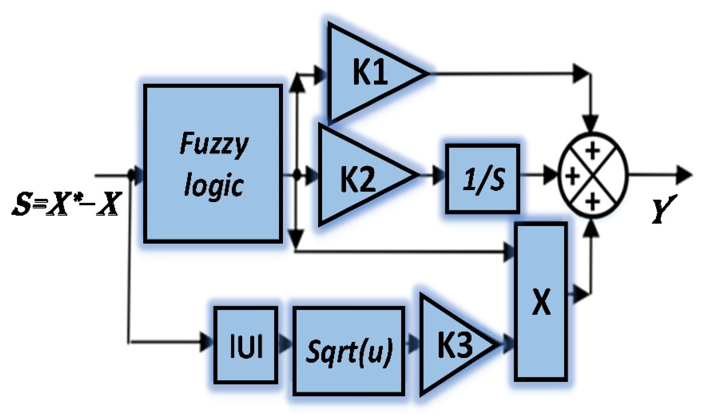
In conventional TOSMC, the sign(u) function may introduce undesirable effects such as chattering. Replacing this function with an FLC mechanism enhances the controller performance, robustness, and tracking capability. Therefore, the proposed FL–TOSMC can be considered an improved version of TOSMC and is mathematically formulated in Equation (23), which is derived from Equation (21).
u t = K 1 × F u z z y + K 2 F u z z y   d t   + K 3 s × ( F u z z y )
where K1, K2, and K3 are the positive gains. With these gains, the DR and performance of the FL-TOSMC controller can be changed.
The FL-TOSMC controller gain values can be calculated using smart strategies such as PSO or grey wolf optimization. Also, the approach can be used for experimentation and simulation to calculate the values of these gains. In this work, the experiment and simulation method were relied upon to calculate the gain values for the FL-TOSMC controller due to its simplicity and ease of obtaining results without writing any complex programs or taking a large amount of time to obtain satisfactory results. The FL-TOSMC method differs from the neural TOSMC technique and the integral SMC technique in terms of performance and effectiveness. The FL-TOSMC approach reduces the chattering phenomenon and does not depend on the MM as in the integral SMC method.
Figure 3 illustrates the proposed FL–TOSMC, developed to enhance the performance of the MPPT strategy of the WT and the DFOC of the DFIG. The proposed controller combines the robustness and finite-time convergence characteristics of the third-order sliding mode controller with the adaptive decision-making capability of the FL method.
As shown in the figure, the sliding surface (S), defined as a function of the tracking error, is used as the input to the FL system. Based on the instantaneous value of the sliding variable, the fuzzy inference mechanism dynamically adjusts the controller gains K1 and K2, enabling the control action to adapt to changes in operating conditions and system uncertainties. The output associated with K1 provides a proportional correction term, while the branch containing K2 and the integrator (1/s) generates an integral action that improves tracking accuracy and reduces steady-state error.
In addition, the nonlinear term (|u|) followed by (sqrt(u)) and gain K3 contributes to the higher-order sliding mode action, enhancing convergence speed and disturbance rejection while mitigating the chattering phenomenon commonly encountered in conventional sliding mode controllers. The outputs of these three control channels are combined to generate the final control signal (Y), which is applied to the DFIG control loops.
The stability of the FL-TOSMC approach can be proven using Lyapunov’s theory, as Equation (22) can be used in this case. There is another simple method that can be relied upon to prove the stability of this designed approach. This strategy is represented by the Bode curve, which is a graphical method that is easy to use and obtains satisfactory results quickly without the need for complex calculations.
The FL-TOSMC approach relies on the FL approach to improve performance. Therefore, the efficiency of the FL-TOSMC approach depends on the characteristics of the FL approach used. Therefore, it is necessary to choose an appropriate number of rules to obtain distinctive and high performance for the FL-TOSMC approach.
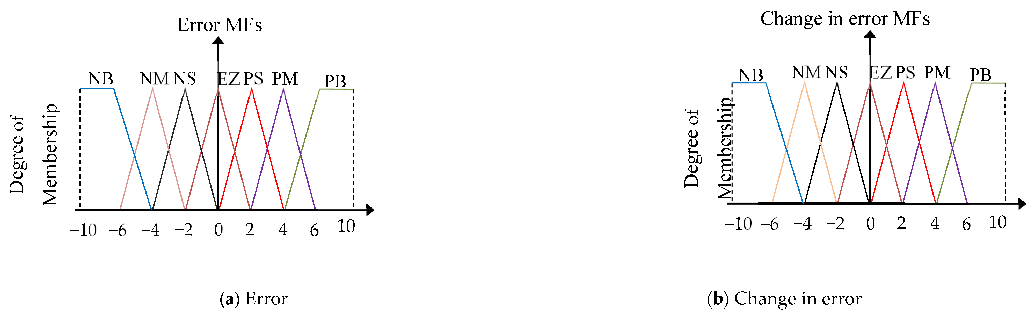
To embody the proposed controller, the FL technology of the Mamdani type was used. Also, an FL controller with 49 rules has been proposed. These rules are listed in Table 1. Figure 4 represents the membership functions used to embody the FL controller of the designer’s approach.
The FL–TOSMC approach can be experimentally implemented using real-time platforms such as dSPACE 1104 or hardware-in-the-loop (HIL) testing. Its implementation is relatively simple and does not require expensive technologies. In this work, FL–TOSMC is employed for two purposes: improving the MPPT performance of the WT, as presented in the following section, and enhancing the DFOC strategy of the DFIG.

4. Proposed MPPT–FL–TOSMC Approach

The MPPT technique is widely used in renewable energy systems to maximize energy extraction under variable operating conditions. It has been successfully applied in PV systems [62] and WT control applications [63]. In WECSs, MPPT determines the optimal reference Ps (Ps∗) according to WS variations. However, conventional MPPT methods based on PI controllers suffer from limited robustness under system parameter variations.
Several advanced approaches have been proposed to overcome these limitations. In [64], a BC-based MPPT strategy improved robustness and tracking performance, but its implementation complexity and large number of tuning parameters remain important drawbacks. The particle swarm optimization-based MPPT proposed in [65] enhanced controller parameter selection; however, its performance deteriorated under parameter uncertainties. A neural network–backstepping (NN–BC) MPPT strategy was introduced in [66], providing improved PQ and robustness, but with increased complexity, cost, and implementation difficulties. Similarly, FL-based MPPT [67] and feed-forward neural network (FF-NN)-based MPPT [68] achieved better performance than conventional methods, although they suffer from tuning difficulties and the absence of systematic design rules. In [69], a super-twisting controller-based MPPT strategy improved PQ; however, chattering effects remained a limitation.
Based on these observations, this section proposes a new MPPT strategy based on the FL–TOSMC approach to improve WT energy extraction while maintaining robustness, simplicity, and model independence. First, the conventional TSR-based MPPT strategy is presented.

4.1. TSR-Based MPPT Algorithm Structure

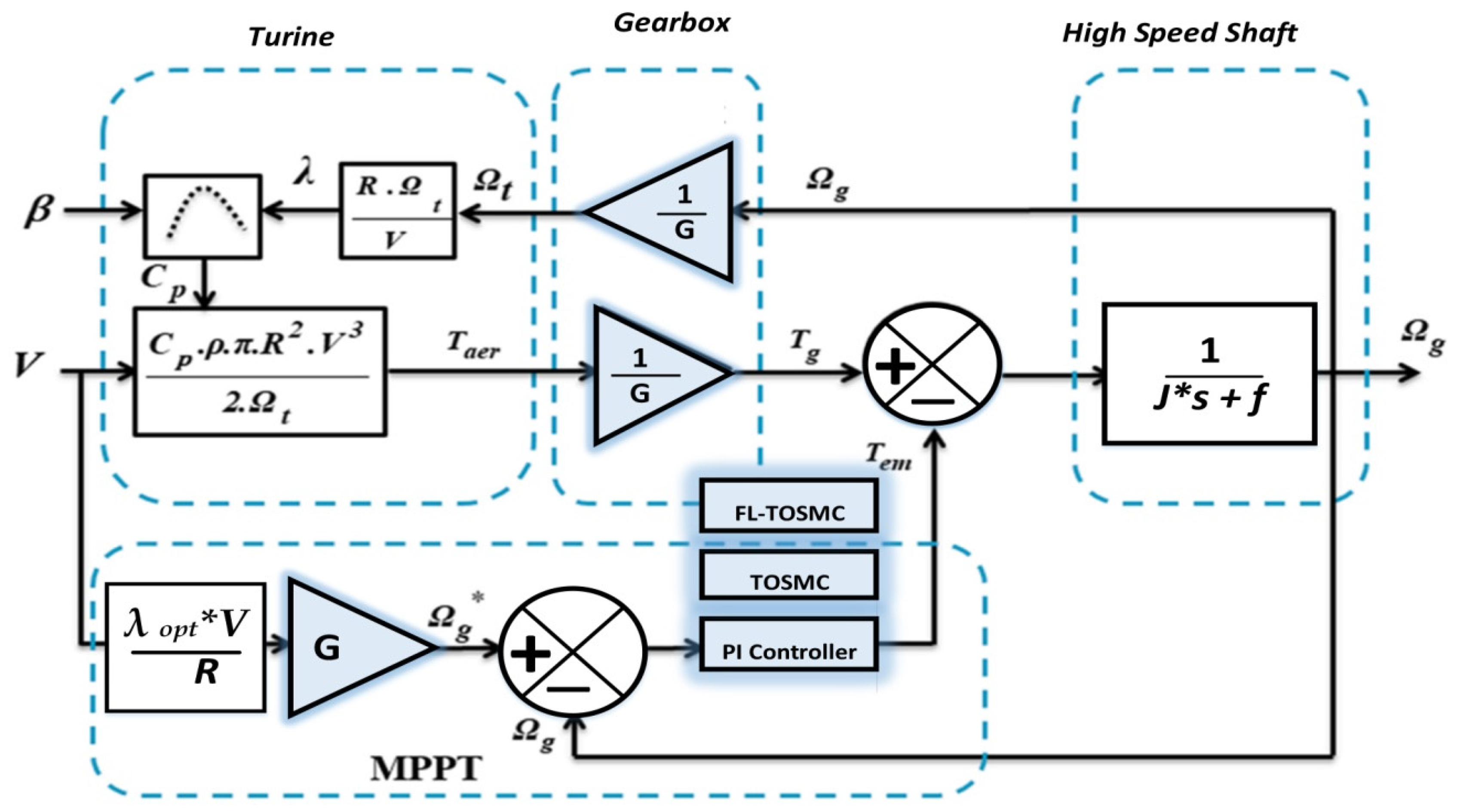
MPPT algorithms aim to maximize the power extracted from wind turbines by adjusting the operating speed according to WS variations. This adjustment affects the generated torque and consequently the quadrature rotor current (iqr) of the DFIG [70]. Among different MPPT methods, the TSR technique is widely adopted due to its simple implementation and fast response [71]. The main objective of the TSR method is to maintain the TSR at its optimal value (λopt) to maximize Cp(λ,β) [72]. Therefore, the reference generator speed Ω g is calculated using Equation (24).
Ω g = λ o p t R V
The value of the generator torque is related to the value of the aerodynamic torque by Equation (25).
T g = 1 G T a e r
where Taer is the aerodynamic torque.
The MPPT method is used to determine the torque reference value. Using the torque reference value, the power reference value can be extracted.
The relationship between the speed of the generator and the difference between the torque of the generator and the turbine is shown in Equation (26).
Ω g = 1 J s + f ( T g T e m )
where Tem is the electromagnetic torque.
The electromagnetic moment can be expressed by Equation (27).
T e m = K p e Ω + K i e Ω d t
where e is the speed generator error (e = g∗ − g).
According to [73], a speed controller is required to minimize the error between the reference speed given by Equation (24) and the measured generator speed. Conventional MPPT schemes generally employ PI controllers because of their simple implementation; however, their performance degrades under rapid reference variations and parameter uncertainties, resulting in a slower dynamic response [74]. To address these limitations, a TOSMC-based MPPT strategy was proposed in [75], providing faster convergence and higher robustness than the conventional PI-based approach.

4.2. MPPT–TOSMC Technique

The MPPT–TOSMC strategy replaces the conventional PI regulator with a third-order sliding mode controller to improve MPPT. Compared with the MPPT–PI approach, it provides faster and more accurate tracking, higher robustness against disturbances and parameter variations, reduced chattering, and improved energy extraction while remaining simple to implement. To ensure accurate tracking of the optimal generator speed, the sliding surface of the TOSMC-based MPPT controller is defined by Equation (28):
S Ω = Ω g Ω g
According to the MPPT-TOSMC strategy, the torque expression is written by Equation (29).
T e m = K 1 × s i g n ( S Ω ) + K 2 s i g n S Ω d t   + K 3 S Ω × s i g n ( S Ω )
The stability condition for this technique is given by Equation (30).
S Ω × S Ω ˙ < 0
According to [43], the MPPT–TOSMC strategy still exhibits current and power ripples, limiting the achieved PQ. Therefore, a more effective control strategy is required to further enhance the MPPT performance.

4.3. MPPT–FL–TOSMC Technique

This subsection presents the proposed MPPT–FL–TOSMC strategy, which extends the conventional MPPT–TOSMC approach by integrating the FL technique described in [76]. The proposed hybrid controller combines the adaptive capability of FL with the robustness of TOSMC to achieve faster and more accurate MPPT while improving PQ and reducing power fluctuations. Moreover, the proposed method is simple to implement, does not require an accurate mathematical model, and differs from the approach reported in [77]. The reference torque is determined using Equation (31).
T e m = K 1 × F u z z y ( S Ω ) + K 2 F u z z y S Ω d t   + K 3 S Ω × F u z z y ( S Ω )
Using the FL-TOSMC strategy significantly improves the performance of wind-based power generation systems, offering a robust and efficient solution to maximize energy production. This proposed approach is represented in Figure 5. Figure 5 illustrates the detailed architecture of the proposed FL-TOSMC strategy. The controller is designed to maximize energy harvesting while protecting the DFIG from mechanical stress. The TOSMC core uses high-order sliding surfaces to ensure robust tracking of the Ps and Qs references under variable wind profiles. To overcome the inherent chattering problem of conventional SMC method, the FL) block dynamically adjusts the switching gains based on the sliding surface error ( e ) and its derivative ( e ) . This intelligent adaptation smooths out the control signal, reduces THD, and ensures that the WT continuously operates at its MPPT with high efficiency and minimum energy loss.

5. Proposed DFIG Power Control Technique

This section presents the proposed DFIG power control strategy aimed at improving PQ, reducing current THD, and enhancing the dynamic response of Ps and Qs. Since the proposed method is developed from the conventional DFOC, the DFOC–PI strategy is first briefly reviewed.

5.1. DFOC–PI Technique

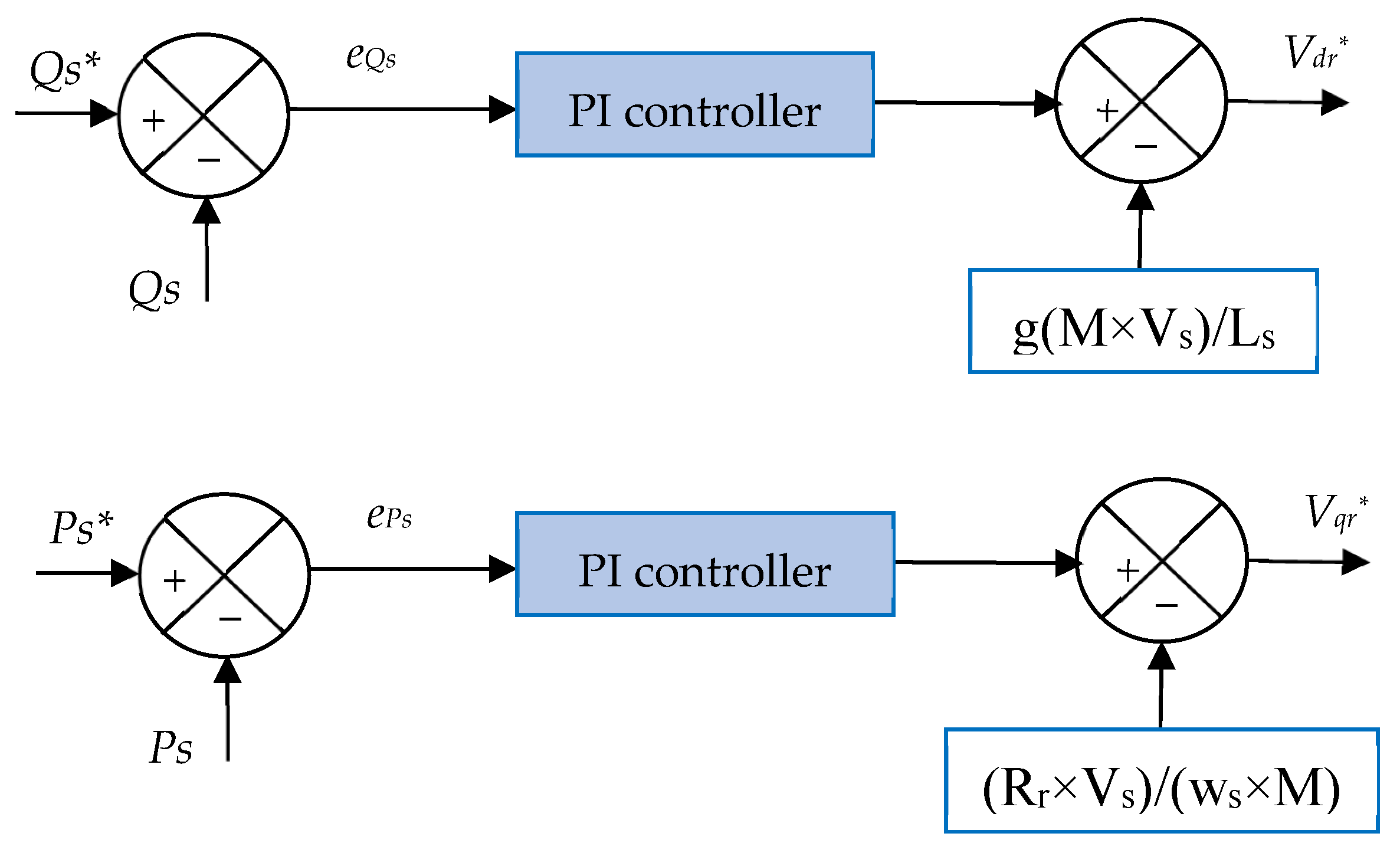
The DFOC strategy is a widely adopted FOC scheme for DFIGs because of its simple implementation, low computational complexity, and fast dynamic response [78]. In the conventional DFOC approach, PI controllers regulate the AC stator Ps and Qs based on the DFIG mathematical model [79]. The generated voltage references are typically converted into switching signals using space vector modulation, which improves power ripple performance at the expense of increased implementation complexity. According to [46], the reference voltage components of the DFOC–PI strategy are calculated using Equations (32) and (33).
V r d = K 1 e P s g × M V s L s + K 2 e P s d t
V r q = K 3 e Q s R r V s M × w s + K 4 e Q s d t
where ePs are eQs are the power errors, K1 and K2 are the PI controller gains for Ps, and K3 and K4 are the PI controller gains for Qs.
The values of the gains of K1, K4, K3, and K2 can be calculated using a genetic algorithm, or the simulation and experimentation method can be used.
Figure 6 represents a schematic diagram of the DFOC-PI method used for power control of DFIG. The DFOC-PI method determines the voltage values of the rotor part in the dq axis.
The reference voltage components obtained from Equations (32) and (33) are converted into switching signals for the RSC using the SVM technique. SVM is widely employed in renewable energy systems because it reduces switching losses and harmonic distortion, thereby improving energy efficiency and PQ [80]. In the DFOC–PI strategy, the estimation of Ps and Qs requires prior estimation of the stator flux, which is used to compute the power errors. The stator flux is calculated using Equation (34).
φ r β = 0 t ( V r R r × i r β ) d t φ r α = 0 t ( V r R r × i r α ) d t
Using Equation (34), the flux value of the rotor part can be calculated according to Equation (35).
φ r = φ r β 2 + φ r α 2
The rotor part voltage can be used to calculate flux, as Equation (36) can be used to calculate flux directly from voltage.
V r ¯ = φ r ¯ × w r
Equation (37) represents the power estimate used in this work.
Q s = 3 2 V s σ × L s × φ β r V s × L m σ × L r × L s × φ α r P s = 3 2 V s × φ r β × L m σ × L r × L s
Despite its simplicity and fast dynamic response, the conventional DFOC–PI strategy suffers from significant power and current ripples, relatively high current THD, and limited robustness against machine parameter variations. These limitations motivate the development of more robust control strategies [43].

5.2. DFOC–TOSMC Technique

To overcome the shortcomings of DFOC–PI, the TOSMC-based DFOC strategy proposed in [46] replaces the conventional PI controllers with TOSMC regulators. This modification improves dynamic response, robustness, and energy conversion performance while preserving the simple structure of the conventional DFOC scheme. In the proposed DFOC–TOSMC strategy, the reference voltage components are determined using Equations (38) and (39).
V r q = K 1 × s i g n ( e P s ) + K 2 s i g n e P s d t   + K 3 e P s   × s i g n ( e P s ) g × M V s L s
V r d = K 4 × s i g n ( e Q s ) + K 5 s i g n e Q s d t   + K 6 e Q s   × s i g n ( e Q s ) R r V s M × w s
where Vrd∗ is the direct rotor voltage and Vrq∗ is the quadrature rotor voltage.
The reference voltage components are converted into switching signals through the SVM technique. The combination of DFOC, TOSMC, and SVM improves the dynamic performance and efficiency of WECSs. However, despite its superior performance over the conventional DFOC–PI strategy, the DFOC–TOSMC approach remains sensitive to DFIG parameter variations, leading to increased power ripples and current THD under disturbed operating conditions [46]. These limitations motivate the development of a more robust control strategy.

5.3. Proposed DFOC–FL–TOSMC Technique

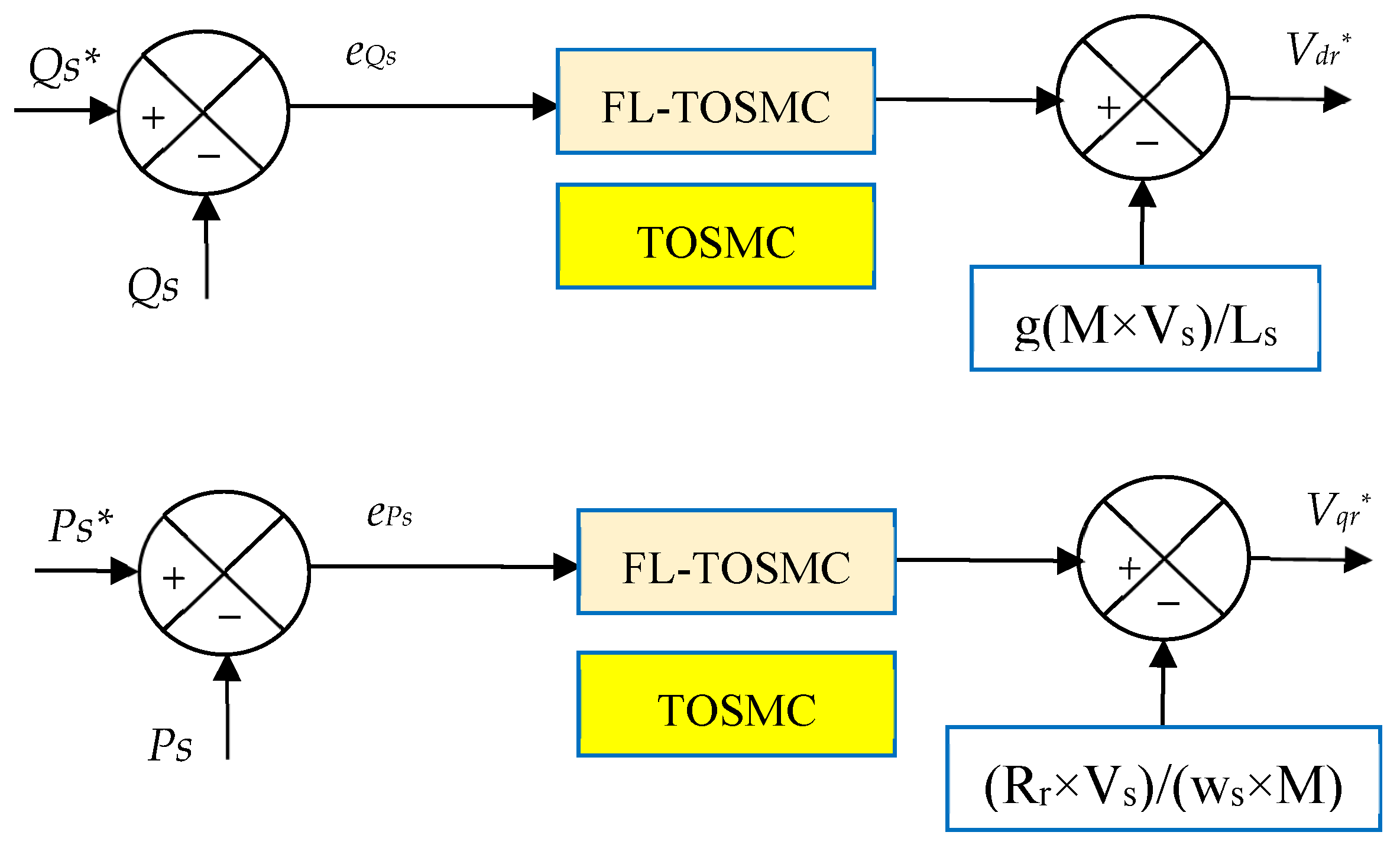
This subsection presents the proposed DFOC–FL–TOSMC strategy, which enhances the DFOC–TOSMC scheme by replacing the TOSMC regulator with the FL–TOSMC controller introduced in Section 3.2. By combining the robustness of TOSMC with the adaptive capability of FL, the proposed controller effectively handles system uncertainties and nonlinearities, resulting in improved stability, tracking accuracy, and PQ. The FL–TOSMC controller generates the reference voltage components from the power errors, as expressed by Equations (40) and (41).
V r q = K 7 × F u z z y ( e P s ) + K 8 F u z z y e P s d t   + K 9 e P s   × F u z z y ( e P s ) g × M V s L s
V r d = K 10 × F u z z y ( e Q s ) + K 11 F u z z y e Q s d t   + K 12 e Q s   × F u z z y ( e Q s ) R r V s M × w s
where K7, K9, and K8 are the FL-TOSMC controller gains for Ps, and K10, K11, and K12 are the PI controller gains for Qs.
The gain values of the FL-TOSMC controller for the designed strategy can be calculated using the simulation and experimentation method due to its ease of use and the speed of obtaining results without the need to write complex programs. Smart strategies can also be used to calculate FL-TOSMC controller gain values. However, the method of simulation and experimentation was used in this work to calculate the gain values. Figure 7 represents the internal structure of the proposed DFOC-FL-TOSMC strategy for power control.
The use of the FL-TOSMC controller in the DFOC strategy allows for improved tracking of references with high accuracy and allows for improved stability over time. The use of this strategy effectively reduces transient oscillations (chattering), thus reducing electrical losses associated with transients and frequent switching. In the next part, the DFOC-SVM approach based on the FL-TOSMC controller is implemented using MATLAB.
Table 2 compares the proposed FL–TOSMC strategy with conventional DPC and DTC methods based on the literature reviewed above, and the simulation results are presented in the next section. The comparison indicates that the proposed approach achieves superior PQ and current performance. However, DPC and DTC remain simpler to implement, require fewer tuning parameters, and generally involve lower implementation cost than the proposed method.
The stability of nonlinear control strategies, such as FL-based controllers and FL–BC approaches, can be evaluated using frequency-domain analysis. Although these controllers do not always have a straightforward linear representation, their stability characteristics can be investigated through an equivalent linearized model or by analyzing the closed-loop system response. The Bode plot obtained using MATLAB provides an effective tool for assessing stability margins, including gain margin and phase margin. A positive gain margin and sufficient phase margin indicate that the designed nonlinear controller can maintain stable operation and robustness against disturbances. Consequently, MATLAB-based Bode analysis can be used to verify the stability performance of advanced nonlinear control strategies, such as FL controllers and FL–BC controllers.
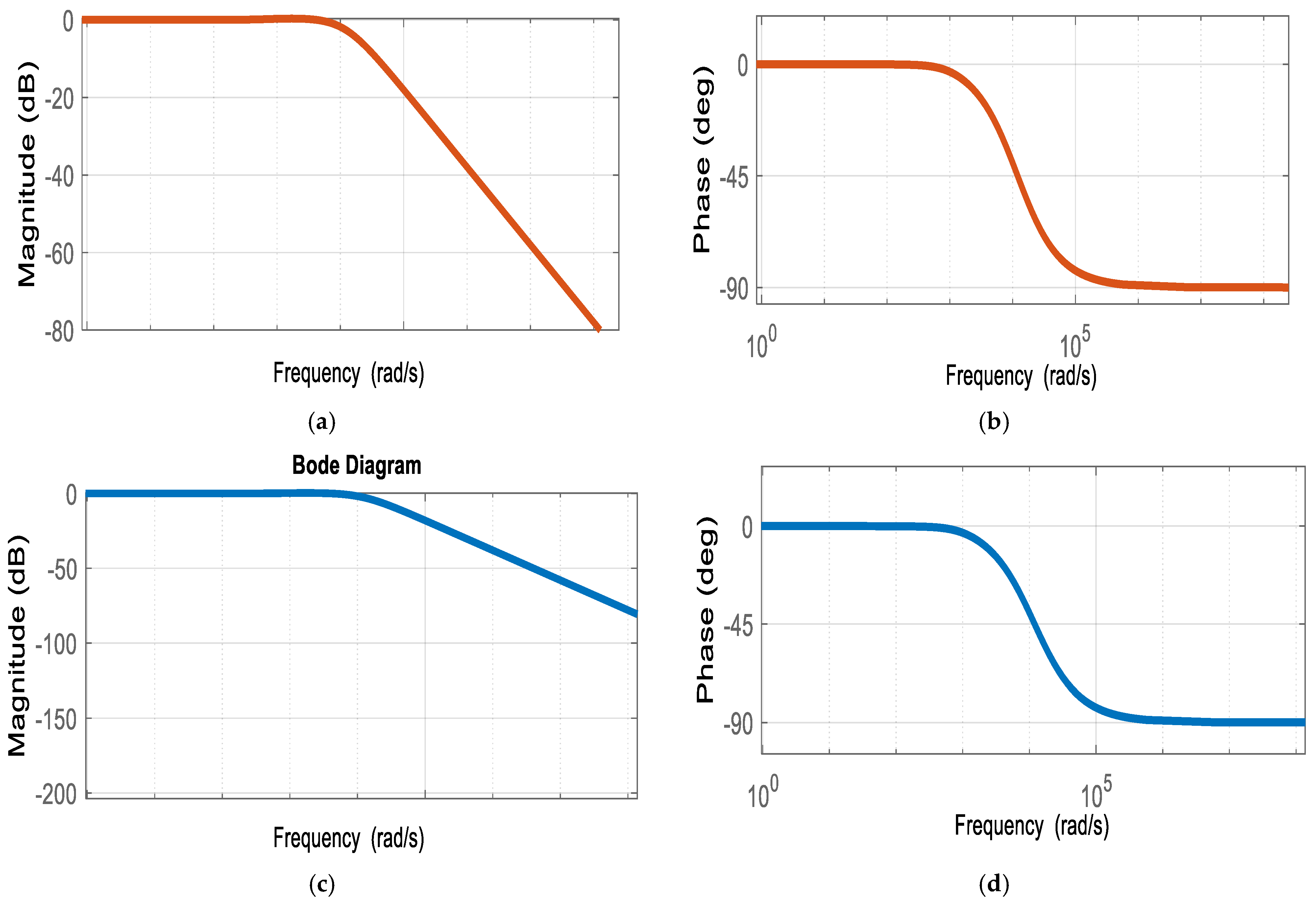
The stability of the designed approach can be proven using Lyapunov’s theorem. Lyapunov’s theory is based on calculations, which makes it somewhat complicated, especially in the case of a complex system. Another reliable method to prove the stability of the proposed approach. This method uses the Bode curve. The Bode curve is a graphical method by which the stability of the proposed approach can be proven easily and does not require complex calculations. MATLAB extracts the Bode curve for the controllers used in this work. Figure 8 represents the Bode curve for two controls. This curve gives the variation in both magnitude (dB) and phase (deg) as a function of frequency for two controls. It is noted that the change in frequency is accompanied by a change in the value of both magnitude (dB) and phase (deg). From Figure 8, it is noted that for the traditional approach, the magnitude (dB) value changes from 0 dB to −80 dB (see Figure 8a), and in the case of the proposed controller, it changes from 0 dB to −120 dB (see Figure 8b). The magnitude (dB) value taking negative values highlights the stability of the proposed approach. Also, it is noted that the phase (deg) value in the case of two controls changes from 0 deg to −90 deg. Therefore, the two approaches are very stable.

6. Results

This section evaluates the effectiveness of the proposed FL–TOSMC strategy through MATLAB simulations and compares its performance with the DFOC–TOSMC approach. The system parameters are provided in Appendix A, together with the FL–TOSMC controller gains used for the MPPT–TSR algorithm and the regulation of Ps and Qs. The same controller parameters are adopted for both Ps and Qs control.
Two different WS profiles are considered to assess the proposed strategy under various operating conditions. The comparison focuses on reference tracking, PQ, current THD, overshoot, and SSE.
(a) First test
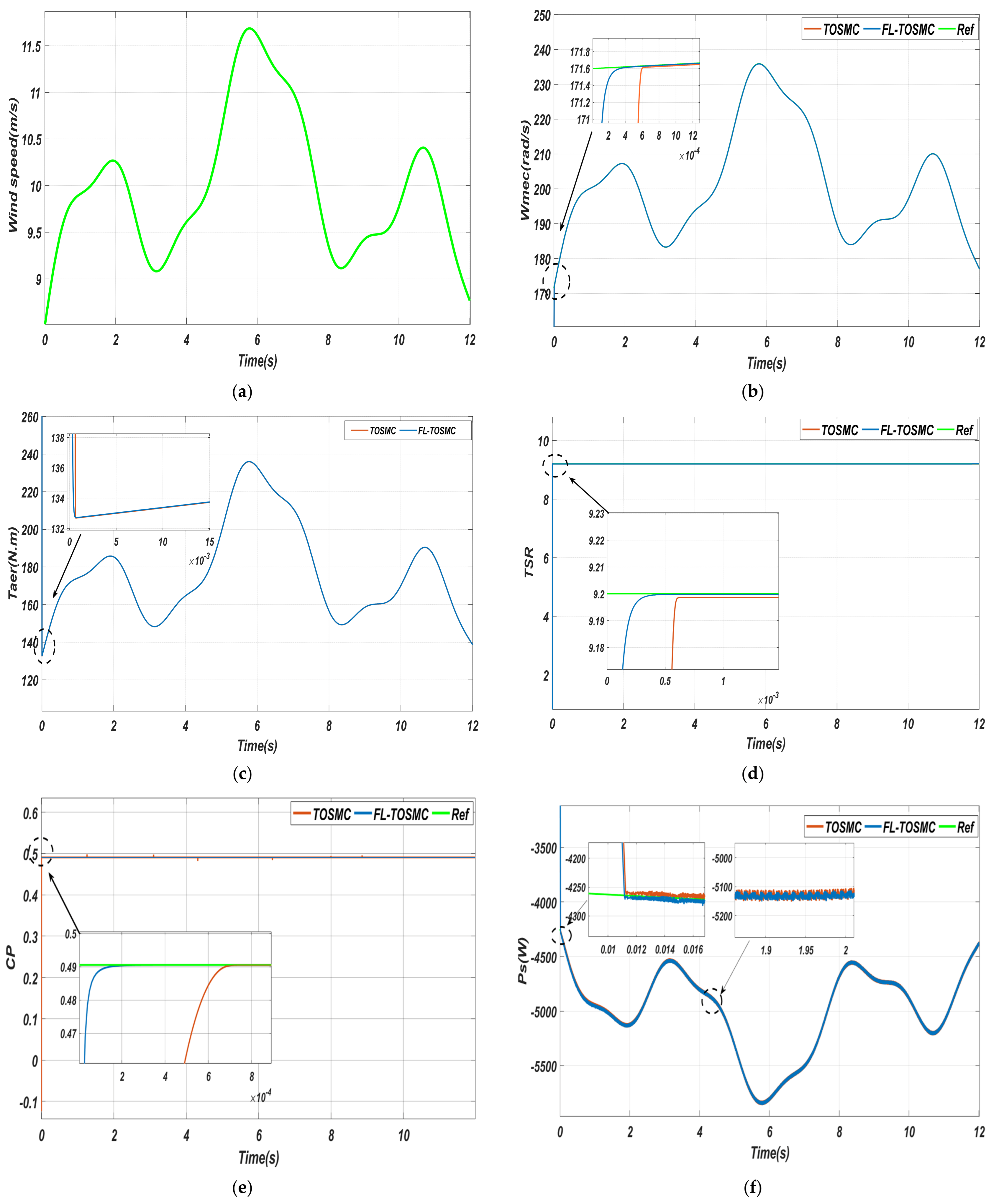
The first test is conducted to evaluate the dynamic performance of the proposed control strategies (TOSMC and FL–TOSMC) under variable WS conditions. The WS profile applied in this test is shown in Figure 9a. The corresponding simulation results are presented in Figure 9 and Figure 10, while the quantitative performance indices are summarized in Table 3.
Figure 9b illustrates the rotor rotational speed of the DFIG. It is observed that the rotor speed closely follows the variations in WS, reflecting the effectiveness of the MPPT control strategy. In both cases, the speed profile exhibits the same general trend as the wind profile; however, the proposed FL–TOSMC demonstrates a faster response time, improved tracking accuracy, and reduced transient deviations compared with the conventional TOSMC. This indicates enhanced dynamic performance and better damping characteristics under changing operating conditions.
Figure 9c presents the aerodynamic torque response for both controllers. The torque varies consistently with WS changes, confirming proper energy conversion behavior. Nevertheless, FL–TOSMC achieves smoother torque dynamics with reduced oscillations and faster settling time, which reflects improved stability in the mechanical-to-electrical energy conversion process.
Figure 9d shows the TSR. It is observed that the TSR is effectively regulated around its optimal value, ensuring maximum power extraction. The proposed FL–TOSMC maintains the TSR more efficiently under transient wind variations, with faster convergence compared to TOSMC, indicating improved MPPT performance.
Figure 9e represents the power coefficient, which remains close to its optimal value (approximately 0.5) during operation. Although the power coefficient is theoretically constrained by turbine characteristics, the proposed controller ensures faster convergence to the optimal operating point after wind-speed changes. FL–TOSMC achieves a quicker stabilization of power coefficient, demonstrating improved energy capture efficiency.
Figure 9f shows the Ps response for both controllers. The Ps closely follows its reference and varies according to WS fluctuations, including negative values during certain operating conditions. The FL–TOSMC controller provides superior performance in terms of faster response, reduced overshoot, and lower ripple content compared to TOSMC, indicating improved power regulation capability.
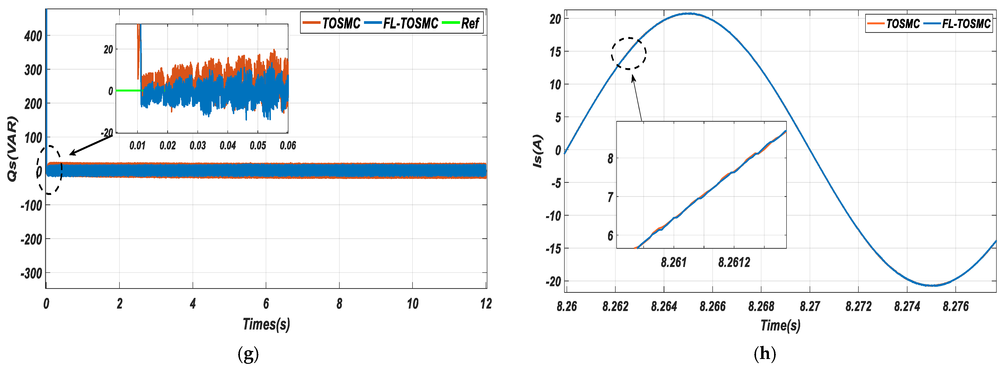
Figure 9g illustrates the Qs. It is observed that Qs remains well regulated and approximately constant despite variations in WS, confirming effective decoupling between Ps and Qs control. However, FL–TOSMC achieves faster dynamic response and significantly reduced ripple levels compared to the conventional controller, reflecting improved voltage regulation performance.
Figure 9h presents the stator current waveforms. The results show that the current remains sinusoidal for both control strategies, confirming stable grid-connected operation. However, the FL–TOSMC controller produces a cleaner waveform with lower distortion and reduced transient oscillations. The variation in current magnitude is consistent with changes in WS due to the MPPT mechanism, which adjusts the Ps reference accordingly. Overall, the proposed controller ensures higher current quality and improved dynamic behavior compared with TOSMC.
These results collectively demonstrate the effectiveness of the FL–TOSMC approach in enhancing both the mechanical and electrical performance of the DFIG system. The proposed controller provides improved tracking accuracy, faster transient response, reduced ripples, and better PQ compared with the conventional TOSMC strategy, confirming its suitability for high-performance WECSs.
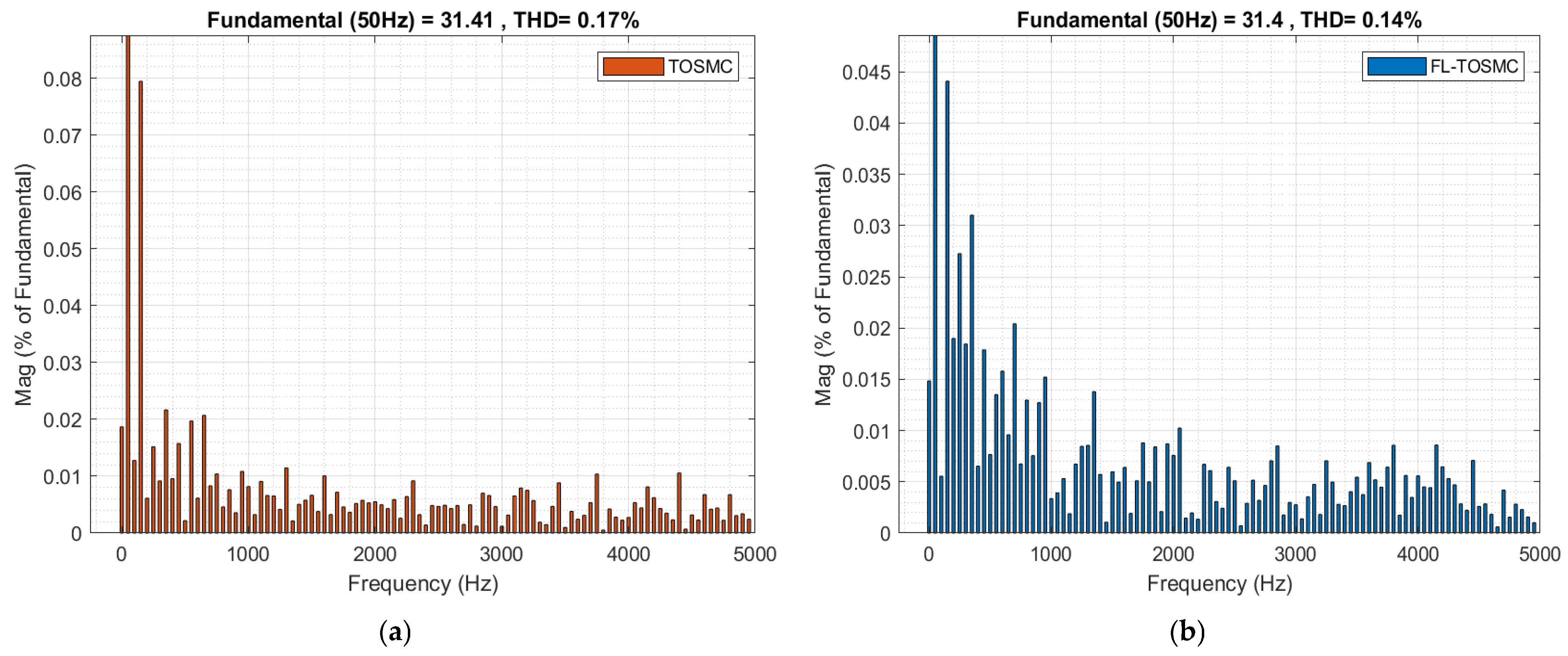
Figure 10 compares the stator current THD obtained with the conventional TOSMC and the proposed FL–TOSMC strategies under the first test. As shown, the proposed controller reduces the THD from 0.17% (Figure 10a) to 0.14% (Figure 10b), corresponding to an improvement of approximately 17.65%. This reduction demonstrates the superior ability of FL–TOSMC to suppress harmonic components and improve current quality.
The lower THD indicates that the proposed controller effectively attenuates high-frequency oscillations associated with converter switching and transient dynamics, resulting in smoother stator currents and improved electromagnetic torque behavior. Moreover, both strategies preserve the same fundamental current component at 50 Hz, confirming that the THD reduction is achieved through harmonic suppression rather than changes in the fundamental power level.
These results demonstrate that the proposed FL–TOSMC strategy provides better current quality than the conventional TOSMC, making it well suited for grid-connected DFIG-based WE systems.
Table 3 compares the dynamic and steady-state performances of the conventional TOSMC and the proposed FL–TOSMC controllers under Test 1. The proposed controller consistently outperforms TOSMC in terms of power ripples, response time, overshoot, and SSE.
For Ps, the ripple is reduced from 31 W to 16 W (48.38%), while the Qs ripple decreases from 20 VAR to 13.2 VAR (34%). These improvements result from the adaptive capability of the FL component, which mitigates oscillations and stabilizes the power exchange between the stator and rotor.
The overshoot of Ps remains almost unchanged (4260 W versus 4269 W, −0.211%), whereas the overshoot of Qs is dramatically reduced from 29.91 VAR to 0.49 VAR (98.36%), indicating a significant improvement in transient damping.
The dynamic response is also enhanced, with RT decreasing from 0.21 ms to 0.11 ms (47.61%) for Ps and from 0.12 ms to 0.08 ms (33.33%) for Qs. Moreover, the SSE is reduced from 0.10 to 0.05 (50%) for Ps and from 0.50 to 0.15 (70%) for Qs, demonstrating improved tracking accuracy and robustness against parameter uncertainties.
Overall, the results confirm that integrating FL with TOSMC significantly improves both transient and steady-state performance, leading to smoother power regulation and more stable operation of the DFIG-based WECS.
(b) Second test
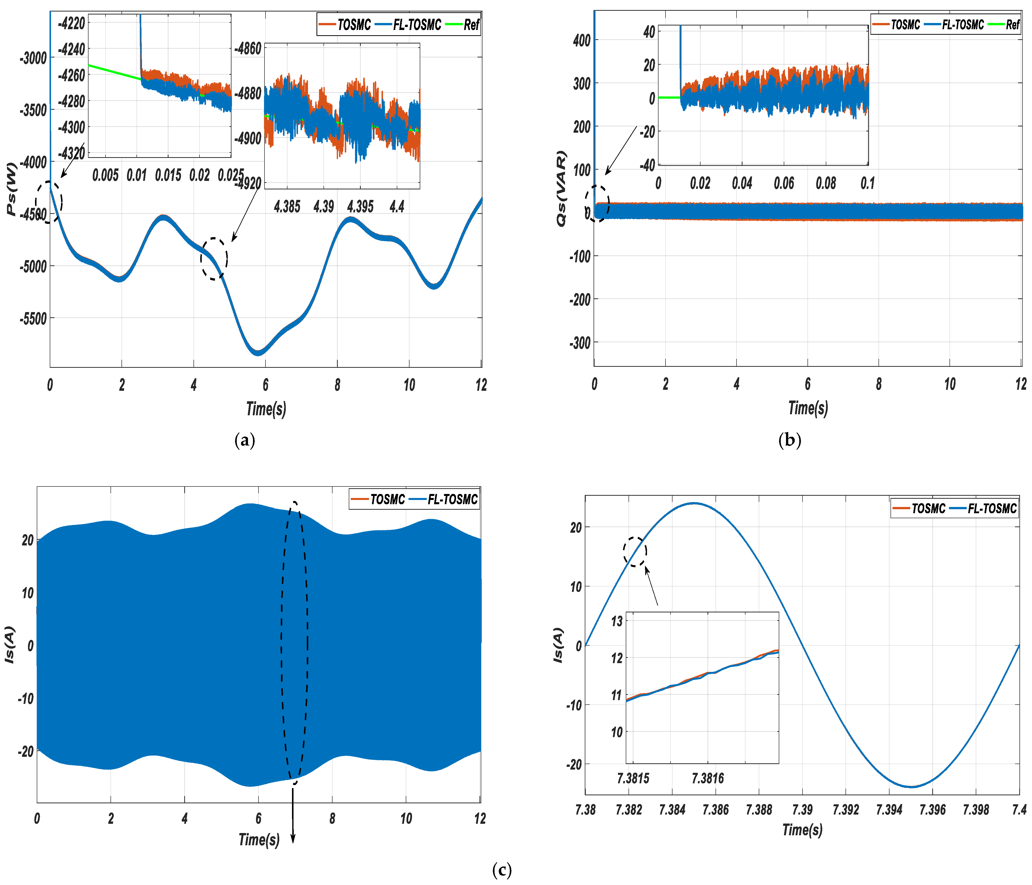
The objective of this test is to evaluate the robustness of the TOSMC and FL–TOSMC controllers under DFIG parameter variations. For this purpose, the stator and rotor resistances (Rs, Rr) are doubled, while the mutual and leakage inductances (Lm, Ls, Lr) are reduced by 50%. The same WS profile as in Test 1 is applied to ensure a fair comparison, and the obtained results are presented in Figure 11 and Figure 12.
Figure 11a shows the Ps response under parameter uncertainties. Both controllers maintain reference tracking; however, FL–TOSMC provides faster convergence, lower settling time, and reduced power ripples compared with TOSMC, demonstrating improved robustness and power regulation capability.
Figure 11b presents the Qs response. Although both controllers maintain acceptable regulation despite parameter variations, FL–TOSMC achieves faster dynamics, better disturbance rejection, and lower Qs oscillations, confirming its enhanced robustness.
The stator current waveform shown in Figure 11c remains sinusoidal for both approaches under severe parameter changes. Nevertheless, FL–TOSMC produces a smoother current with reduced harmonic distortion, indicating improved current quality and harmonic suppression capability.
Overall, Figure 11 and Figure 12 confirm the superiority of the proposed FL–TOSMC strategy under uncertain operating conditions. By maintaining accurate power tracking, reducing oscillations, and improving PQ, the proposed controller provides a more reliable solution for DFIG-based WECSs.
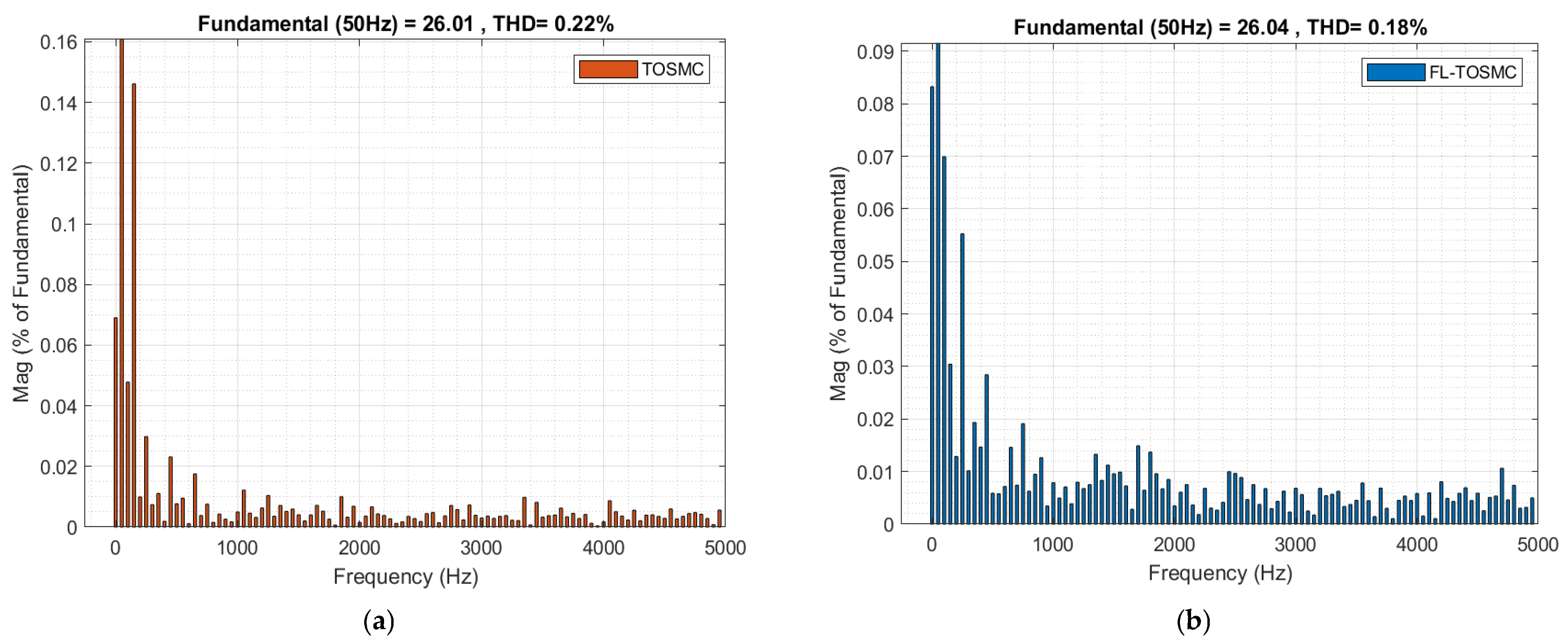
Figure 12 presents the comparison of stator current THD for the DFIG system under the TOSMC and FL–TOSMC control strategies in Test 2. As shown in Figure 12a, the conventional TOSMC yields a THD value of 0.22%, whereas the proposed FL–TOSMC approach reduces this value to 0.18%, as illustrated in Figure 12b. This corresponds to a reduction of approximately 18.18% in current harmonic distortion, confirming the superior capability of the proposed controller in improving PQ.
From a physical perspective, the reduction in THD is directly related to the improved smoothness of the stator current waveform. Lower harmonic content reduces unwanted oscillations in the electromagnetic torque and decreases additional copper and iron losses associated with high-frequency current components. Since harmonic currents contribute to extra heating in the stator windings, their reduction leads to improved electrical performance and more stable generator operation under variable wind conditions.
In addition, it is observed that both control strategies maintain the fundamental component of the stator current at approximately 50 Hz. However, the FL–TOSMC approach exhibits a higher amplitude of the fundamental component compared to the conventional TOSMC, indicating improved utilization of the generated power and more effective energy conversion. This improvement is consistent with the enhanced tracking capability and reduced oscillations achieved by the proposed controller.
Overall, the results demonstrate that the FL–TOSMC strategy significantly enhances current quality by reducing harmonic distortion while preserving the fundamental frequency component, making it a promising control approach for high-performance DFIG-based WECSs and other industrial applications requiring strict PQ standards.
Table 4 summarizes the dynamic and steady-state performance of the conventional TOSMC and the proposed FL–TOSMC controllers under Test 2 operating conditions. The obtained results clearly demonstrate the effectiveness of the proposed controller in improving PQ, tracking accuracy, and transient response.
For Ps, the ripple magnitude is reduced from 48 W with TOSMC to 22 W with FL–TOSMC, corresponding to a reduction of 54.16%. Likewise, the Qs ripple decreases from 31.7 VAR to 20.31 VAR, representing a reduction of 35.9%. This improvement indicates that the proposed controller is more effective in attenuating oscillations caused by wind-speed variations and system nonlinearities. From a physical perspective, the FL mechanism continuously adapts the controller gains according to the operating conditions, while the third-order sliding mode action suppresses high-frequency oscillations, resulting in smoother Ps and reactive power profiles and enhanced PQ.
Regarding overshoot, the Ps response exhibits only a negligible variation, changing from 4259 W to 4265 W, which corresponds to a difference of approximately −0.14%. This result indicates that both controllers provide a similar transient peak for Ps regulation. However, a substantial improvement is achieved in Qs control, where the overshoot decreases from 9.669 VAR to only 1.32 VAR, corresponding to an 86.34% reduction. Such a reduction demonstrates the superior damping capability of the FL–TOSMC controller, which effectively limits excessive transient excursions and reduces oscillatory behavior during reference changes and disturbances.
The RT is also significantly improved. For Ps regulation, the RT decreases from 0.20 ms to 0.10 ms, corresponding to a 50% reduction. Similarly, for Qs control, the RT decreases from 0.11 ms to 0.07 ms, yielding a 36.36% reduction. These improvements confirm the ability of the proposed controller to accelerate the convergence of tracking errors and achieve faster stabilization following operating condition changes. The enhanced dynamic response is mainly due to the finite-time convergence property of the TOSMC method combined with the adaptive adjustment provided by the FL system.
Concerning the SSE, the proposed FL–TOSMC controller reduces the Ps error from 0.11 to 0.0748, corresponding to a 32% reduction. For Qs regulation, the SSE decreases dramatically from 1.3 to 0.234, representing an 82% reduction. These results indicate that the proposed controller achieves more accurate reference tracking and better steady-state performance. Physically, the reduction in SSE reflects the controller’s improved capability to compensate for modeling uncertainties and external disturbances while maintaining the operating point close to its desired reference value.
Overall, the results of Table 4 confirm that the FL–TOSMC controller outperforms the conventional TOSMC approach under Test 2 conditions. The proposed controller provides lower power ripples, significantly reduced Qs overshoot, faster RTs, and improved steady-state accuracy, thereby ensuring enhanced robustness, superior PQ, and more stable operation of the DFIG-based WE conversion system.
Table 5 presents a comparison between the results of Test 1 (Table 3) and the results of Test 2 (Table 4). The percentage change is calculated using the following relationship:
C h a n g e % = V a l u e T e s t 2 V a l u e T e s t 1 V a l u e T e s t 1 × 100 %
A comparative analysis was performed to evaluate the variation in overshoot, RT, SSE, and power ripples between Test 1 and Test 2 for both TOSMC and FL-TOSMC controllers.
For Ps, the ripple magnitude of TOSMC increased from 31 W in Test 1 to 48 W in Test 2, corresponding to an increase of 54.84%. Similarly, the ripple magnitude of FL-TOSMC increased from 16 W to 22 W, representing an increase of 37.50%. Although both controllers experienced higher oscillations under Test 2 conditions, FL-TOSMC maintained significantly lower ripple levels.
Regarding Qs, the ripple value increased from 20 VAR to 31.7 VAR for TOSMC (+58.50%) and from 13.2 VAR to 20.31 VAR for FL-TOSMC (+53.86%). Despite the increase, the proposed FL-TOSMC controller continued to provide superior ripple attenuation.
The overshoot of Ps remained almost unchanged for both controllers. TOSMC decreased slightly from 4260 W to 4259 W (−0.023%), while FL-TOSMC increased marginally from 4269 W to 4265 W (−0.094%). For Qs, the overshoot decreased considerably from 29.91 VAR to 9.669 VAR for TOSMC (−67.67%) and increased from 0.49 VAR to 1.32 VAR for FL-TOSMC (+169.39%). Nevertheless, the absolute overshoot of FL-TOSMC remained substantially lower than that of TOSMC.
The RT of Ps improved in Test 2. TOSMC decreased from 0.21 ms to 0.20 ms (−4.76%), while FL-TOSMC decreased from 0.11 ms to 0.10 ms (−9.09%). For Qs, RT decreased from 0.12 ms to 0.11 ms (−8.33%) for TOSMC and from 0.08 ms to 0.07 ms (−12.50%) for FL-TOSMC, indicating faster transient dynamics in Test 2.
Concerning SSE, the SSE of Ps increased from 0.10 to 0.11 for TOSMC (+10.00%) and from 0.05 to 0.0748 for FL-TOSMC (+49.60%). For Qs, SSE increased significantly from 0.50 to 1.30 for TOSMC (+160.00%), whereas FL-TOSMC increased from 0.15 to 0.234 (+56.00%). Although the error increased in both cases, FL-TOSMC consistently maintained lower SSE values.
Overall, the results indicate that Test 2 represents a more demanding operating condition, leading to larger power ripples and SSEs. Nevertheless, the proposed FL-TOSMC controller preserves its superiority over the conventional TOSMC by maintaining lower overshoot, faster RTs, reduced SSEs, and lower power ripples under both test scenarios.
(c) Third test
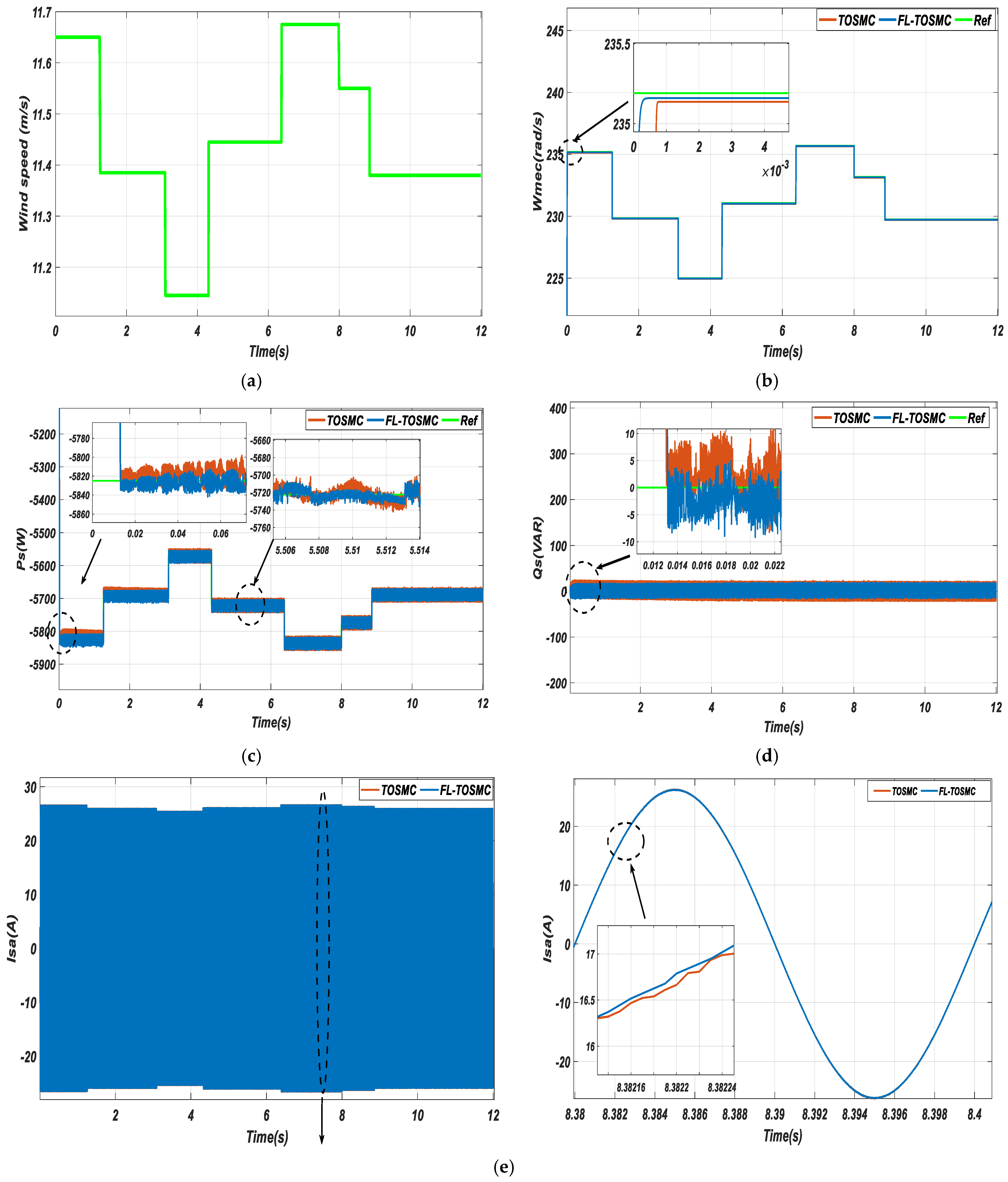
In the third test, the proposed strategy is evaluated under a different stepped WS profile, as shown in Figure 13a. The obtained results are presented in Figure 13 and Figure 14, while the numerical comparisons are summarized in Table 6.
Figure 13 illustrates the dynamic behavior of the DFIG-based WE conversion system using TOSMC and FL–TOSMC controllers. Figure 13b shows that both controllers successfully track the optimal rotor speed required by the MPPT strategy. However, FL–TOSMC provides faster convergence, lower transient deviations, and improved speed tracking due to the adaptive capability of the FL component.
Figure 13c,d presents the Ps and Qs responses, respectively. The active power follows the WS variations accurately for both controllers, but FL–TOSMC achieves smoother tracking with reduced oscillations, lower ripples, and shorter settling time, especially during abrupt WS changes. Qs remains well regulated, confirming the effectiveness of the DFOC decoupling strategy; nevertheless, FL–TOSMC provides faster disturbance rejection and improved stability compared with TOSMC.
The stator current waveform shown in Figure 13e remains sinusoidal for both approaches. However, FL–TOSMC produces a smoother current with reduced distortion and fewer transient oscillations, confirming its ability to improve PQ under variable wind conditions.
Overall, the results of Figure 13 demonstrate that the proposed FL–TOSMC controller outperforms the conventional TOSMC strategy in terms of dynamic response, power-tracking accuracy, ripple reduction, disturbance rejection, and current quality. These improvements confirm its suitability for DFIG-based WECSs operating under rapidly varying wind conditions.
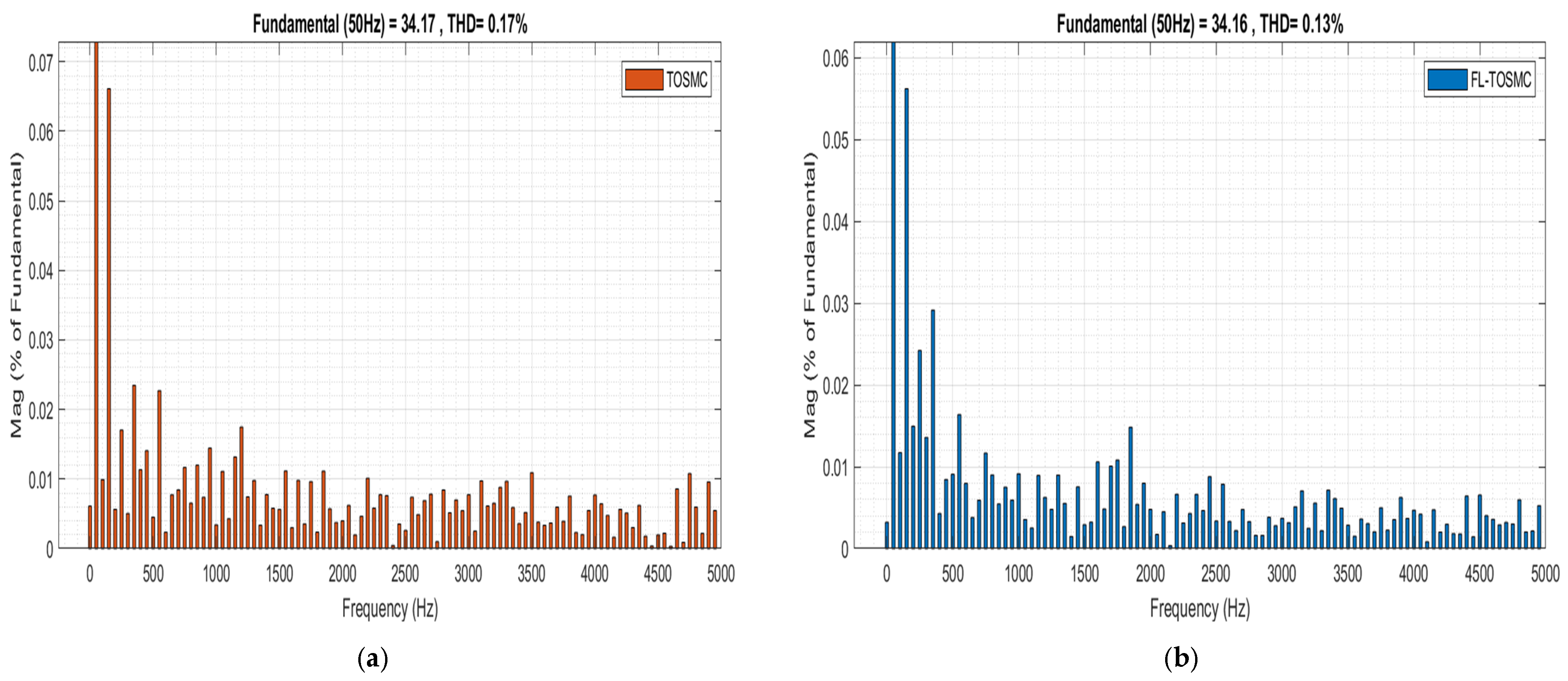
Figure 14 presents the current THD comparison between the conventional TOSMC and the proposed FL–TOSMC controllers. The TOSMC approach results in a THD value of 0.17% (Figure 14a), while FL–TOSMC reduces this value to 0.13% (Figure 14b), corresponding to an improvement of approximately 23.53%.
This enhancement is attributed to the combination of the adaptive capability of FL and the robustness of TOSMC, which enables better disturbance rejection and effective suppression of current oscillations. Consequently, the proposed controller produces a smoother current waveform with reduced harmonic components.
Moreover, the fundamental component at 50 Hz remains almost unchanged for both controllers, confirming that the THD reduction is achieved through harmonic attenuation rather than modification of the fundamental current magnitude. These results demonstrate the effectiveness of FL–TOSMC in improving current quality and satisfying the PQ requirements of grid-connected DFIG-based WECSs.
Table 6 presents the performance comparison between the conventional TOSMC and the proposed FL–TOSMC controllers under Test 3 operating conditions. The results clearly demonstrate the superiority of the proposed controller in terms of power ripple suppression, transient response, and steady-state accuracy.
For Ps, the power ripple amplitude is reduced from 65 W with TOSMC to 13 W with FL–TOSMC, corresponding to an 80% reduction. Similarly, for Qs, the ripple magnitude decreases from 16.7 VAR to 11.52 VAR, representing a 31% reduction. This significant attenuation of oscillations is mainly attributed to the adaptive nature of the FL component, which continuously adjusts the control gains according to the operating conditions. As a result, the controller is able to suppress fluctuations caused by wind-speed variations and parameter uncertainties more effectively than the conventional TOSMC. Lower ripple levels indicate smoother power injection into the grid and improved PQ.
Regarding overshoot, the Ps overshoot remains nearly unchanged, increasing slightly from 5824 W to 5834 W, which corresponds to a negligible variation of only 0.17%. However, a remarkable improvement is observed for the Qs response, where the overshoot is reduced from 19.58 VAR to only 1.74 VAR, corresponding to a reduction of 91.11%. Physically, this behavior indicates that the proposed controller significantly improves damping during transient conditions and prevents excessive energy accumulation in the electromagnetic dynamics of the DFIG, thereby reducing oscillatory behavior after reference changes.
The RT is also improved by the proposed controller. For Ps regulation, the RT decreases from 0.23 ms to 0.17 ms, yielding a reduction of 26.03%. For Qs control, the RT decreases from 0.18 ms to 0.10 ms, corresponding to a reduction of 44%. These improvements confirm that the FL–TOSMC controller accelerates error convergence and allows the DFIG to reach its steady-state operating point more rapidly following disturbances or wind-speed variations. The faster response is a direct consequence of the higher-order sliding mode action combined with the adaptive tuning capability of the FL system.
Concerning the SSE, the proposed controller reduces the Ps error from 8 to 6, corresponding to a 25% reduction. For Qs regulation, the SSE decreases from 2.13 to 0.58, yielding a substantial reduction of 72.76%. The lower SSE values demonstrate the improved tracking precision of the FL–TOSMC approach and its ability to maintain the generated power close to the desired reference values despite the presence of disturbances and system nonlinearities.
Overall, the results of Table 6 confirm that the proposed FL–TOSMC controller provides superior dynamic and steady-state performance compared with the conventional TOSMC. The combination of FL adaptive tuning and TOSMC effectively enhances robustness, accelerates system dynamics, reduces power oscillations, and improves tracking accuracy, making the proposed approach particularly suitable for DFIG-based WECSs operating under variable and challenging conditions.
Table 7 presents a study of the changes in the results obtained for overshoot, RT, SSE, and power ripples between Test 1 and Test 3. A comparative analysis between Test 1 and Test 3 reveals the impact of the changed operating conditions on the dynamic performance of both controllers. For Ps, the ripple magnitude of the conventional TOSMC increased significantly from 31 W in Test 1 to 65 W in Test 3, corresponding to an increase of 109.68%. In contrast, the FL–TOSMC ripple level decreased from 16 W to 13 W, representing a reduction of 18.75%, which demonstrates the superior capability of the proposed controller in suppressing power oscillations under more demanding operating conditions. For Qs, the ripple value decreased from 20 VAR to 16.7 VAR for TOSMC (−16.50%) and from 13.2 VAR to 11.52 VAR for FL–TOSMC (−12.73%).
Regarding overshoot, the Ps overshoot increased from 4260 W to 5824 W for TOSMC (+36.71%) and from 4269 W to 5834 W for FL–TOSMC (+36.66%), indicating a comparable increase for both controllers due to the altered test conditions. For Qs, the overshoot decreased from 29.91 VAR to 19.58 VAR for TOSMC (−34.54%), while it increased from 0.49 VAR to 1.74 VAR for FL–TOSMC (+255.10%). Nevertheless, the absolute overshoot value of FL–TOSMC remained substantially lower than that of TOSMC.
RT also exhibited noticeable variations. For Ps, RT increased from 0.21 ms to 0.23 ms for TOSMC (+9.52%) and from 0.11 ms to 0.17 ms for FL–TOSMC (+54.55%). Similarly, for Qs, RT increased from 0.12 ms to 0.18 ms for TOSMC (+50.00%) and from 0.08 ms to 0.10 ms for FL–TOSMC (+25.00%). Although RTs increased in Test 3, the proposed FL–TOSMC still maintained faster dynamics than the conventional TOSMC.
Concerning SSE, a significant increase was observed under Test 3 conditions. For Ps, SSE increased from 0.1 to 8 for TOSMC (+7900%) and from 0.05 to 6 for FL–TOSMC (+11,900%). For Qs, SSE increased from 0.5 to 2.13 for TOSMC (+326.00%) and from 0.15 to 0.58 for FL–TOSMC (+286.67%). Despite this increase, the proposed FL–TOSMC consistently achieved lower SSE values than TOSMC.
Overall, the comparison between Test 1 and Test 3 demonstrates that Test 3 represents a significantly more challenging operating scenario. Nevertheless, the FL–TOSMC controller preserves its superior performance by maintaining lower power ripples, reduced overshoot in Qs regulation, faster RTs, and smaller SSEs compared with the conventional TOSMC controller.
The results show that Test 3 imposes considerably more demanding operating conditions, particularly in terms of overshoot and SSE. However, the FL-TOSMC controller maintains lower absolute values of ripples, overshoot, RT, and SSE than the conventional TOSMC controller in most performance metrics.
Table 8 represents a study in the change in the THD value for two controls during the three tests performed. Equations (43) and (44) are used to complete this study. This study is based on studying the effect of the THD value on changing the system parameter values and the shape of the WS change. From Table 8, it is noted that the THD value changed in the tests for the two controls. The THD value increased during the second test compared to the first test due to the change in DFIG parameters.
A = T H D t e s t 2 T H D t e s t 1 T H D t e s t 2
B = T H D t e s t 3 T H D t e s t 1 T H D t e s t 3
The DFOC-FL-TOSMC approach presented a percentage change in the THD value between the first and second tests compared to the DFOC-TOSMC approach. This percentage change was 22.73% and 22.22% for both the designed approach and the DFOC-TOSMC approach, respectively. The THD value in the third test did not change compared to the first test if the DFOC-TOSMC approach was used. Therefore, the effect rate is estimated at 0%. However, if the designed approach was used, the THD value decreased in the third test compared to the first test. This decrease was estimated at 7.14%.
This study highlights that the THD value is affected by both a change in DFIG parameters and a change in the shape of the WS. Therefore, it is necessary to propose a control that has high performance and a great ability to improve the THD value, regardless of the shape of the WS or the change in the DFIG parameters. Table 8 gives a clear picture that the designed approach improves the THD value significantly compared to the DFOC-TOSMC approach, which makes it a promising solution in other industrial fields.
Table 9 presents a comparative evaluation of the proposed FL–TOSMC strategy against several advanced control techniques reported in the literature using the THD index as a performance criterion. As can be observed, the proposed controller achieves THD values of 0.14%, 0.18%, and 0.13% under the considered test scenarios, which are among the lowest values reported. Compared with conventional approaches such as TOSMC (0.83%), ISMC (1.33%), DRAPC (1.08%), DPC-STSMC (0.85%), DPC-NSTSMC-SVM (0.99%), ANN-DPC (2.22%), and SMC-SVM control (5.76%), the proposed method provides a substantial reduction in harmonic distortion, indicating superior power-quality performance.
Furthermore, even when compared with high-performance controllers such as DPC-ANFIS-STSMC (0.46%), TOSMC-DRAPC (0.23%), and DFTC-SOCSM (0.23%), the proposed approach consistently achieves lower THD levels. This improvement can be attributed to the effective integration of the FL method and the TOSMC method, where the FL component enhances adaptability to operating condition variations, while the TOSMC component ensures fast error convergence and strong robustness against disturbances and parameter uncertainties. As a result, current and power oscillations are significantly attenuated, leading to improved waveform quality and reduced harmonic content.
Overall, the results presented in Table 9 demonstrate that the proposed FL–TOSMC controller outperforms several recently published control strategies in terms of THD reduction, confirming its effectiveness for enhancing PQ and dynamic performance in DFIG-based WECSs.
Table 10 compares the RTs achieved by the proposed FL–TOSMC controller with those reported in several recent studies. The proposed approach attains response times ranging from 0.10 ms to 0.17 ms for Ps and from 0.07 ms to 0.10 ms for Qs, demonstrating a significantly faster dynamic response than all referenced methods.
For Ps regulation, the best response times reported in the literature are 0.12 ms in [100], 0.31 ms in [100], and 0.90 ms in [90]. Compared with the best literature value of 0.12 ms, the proposed controller achieves a response time of 0.10 ms, corresponding to an improvement of approximately 16.7%. Relative to the 0.31 ms and 0.90 ms values, the improvement reaches 67.7% and 88.9%, respectively. Furthermore, when compared with controllers exhibiting RTs greater than 1 ms, such as [91] (2.2 ms), [94] (15 ms), and [96] (33.8 ms), the proposed method reduces the RT by approximately 95.5%, 99.3%, and 99.7%, respectively.
Similarly, for Qs control, the proposed approach achieves response times between 0.07 ms and 0.10 ms, while the best reported values in the literature are 0.20 ms in [100], 0.46 ms in [95], and 0.80 ms in [102]. Consequently, the proposed controller provides improvements of approximately 65%, 78.3%, and 87.5%, respectively. Even larger gains are observed when compared with slower techniques, such as [90] (2.10–5.40 ms), [94] (80 ms), and [99] (28 ms), where the reduction in response time exceeds 95% and reaches more than 99% in several cases.
The superior dynamic performance of the proposed FL–TOSMC controller can be attributed to the combination of FL method adaptation and the TOSMC method. The FL component continuously adjusts the control action according to the operating conditions, while the third-order sliding mode structure ensures rapid error convergence and strong robustness against parameter uncertainties and external disturbances. This synergy enables the controller to minimize transient duration, accelerate power tracking, and maintain stable operation under varying conditions.
Overall, the results of Table 10 demonstrate that the proposed FL–TOSMC strategy provides one of the fastest power response characteristics reported in the literature, confirming its effectiveness for high-performance DFIG-based WECSs requiring rapid Ps and Qs regulation.

7. Conclusions

This paper proposed a hybrid FL–TOSMC strategy to enhance the performance of a DFIG-based WECS under the DFOC framework. The proposed controller combines the robustness and finite-time convergence of TOSMC with the adaptive capability of FL to improve system performance under variable operating conditions.
The effectiveness of the proposed approach was verified through several simulation tests and compared with the conventional TOSMC strategy. The results demonstrated significant improvements in both transient and steady-state performances. The proposed FL–TOSMC reduced the stator current THD by approximately 17.65%, 18.18%, and 23.53% for the considered tests. Moreover, it achieved substantial reductions in Ps and Qs ripples, reaching up to 80% and 35.9%, respectively. Improvements in RT, SSE, and Qs overshoot further confirmed the enhanced tracking accuracy and PQ performance of the proposed controller.
The robustness evaluation under DFIG parameter variations showed that FL–TOSMC maintains stable operation despite significant changes in machine parameters. The proposed strategy successfully reduced oscillations and preserved accurate tracking, demonstrating its capability to handle uncertainties commonly encountered in practical WECSs.
However, this study has some limitations. The validation was performed only through MATLAB/Simulink simulations without experimental implementation. Furthermore, the robustness analysis was limited to DFIG parameter variations, while other practical disturbances, including grid faults, measurement noise, converter nonlinearities, DC-link voltage fluctuations, and severe wind turbulence, were not considered. In addition, the comparison was mainly performed against TOSMC, while other advanced controllers were evaluated only through literature-based comparisons.
Future research will focus on experimental validation using real-time platforms and HIL testing. Further studies will investigate the performance of the proposed controller under a wider range of disturbances, including grid-voltage disturbances, sensor noise, converter constraints, and DC-link perturbations. Comprehensive comparisons with advanced control techniques, including PI, super-twisting SMC, fuzzy SMC, and optimization-based controllers, will also be conducted. Moreover, automatic parameter tuning using optimization algorithms and the extension of the proposed strategy to hybrid wind–photovoltaic energy systems will be explored.

Author Contributions

A.B.: Conceptualization; Methodology; Software; Validation; Formal analysis; Investigation; Resources; Data curation; Writing—original draft preparation; Writing—review and editing; Visualization; Supervision; Project administration. M.L.: Conceptualization; Methodology; Formal analysis; Investigation; Resources; Data curation; Writing—original draft preparation; Writing—review and editing; Visualization; Supervision. H.B.: Conceptualization; Methodology; Formal analysis; Investigation; Resources; Data curation; Writing—original draft preparation; Writing—review and editing; Visualization; Supervision; Project administration; Funding acquisition. S.G.: Formal analysis; Investigation; Resources; Data curation; Writing—review and editing; Visualization; Supervision. A.M.: Conceptualization; Methodology; Software; Validation; Formal analysis; Investigation; Resources; Data curation; Writing—original draft preparation; Writing—review and editing; Visualization; Supervision. G.B.: Conceptualization; Methodology; Formal analysis; Investigation; Resources; Data curation; Writing—review and editing; Visualization; Supervision. N.B.: Methodology; Formal analysis; Investigation; Resources; Writing—review and editing; Visualization; Supervision; Project administration; Funding acquisition. All authors have read and agreed to the published version of the manuscript.

Funding

This research was fully supported by the PubArt program of the National University of Science and Technology POLITEHNICA Bucharest, and partially supported by the Experimental—Demonstration project PN-IV-P7-7.1-PED-2024-0567 (Improving the Fuel Cell Hybrid Electric Vehicle Drivetrain by Implementing a Novel Optimal Real-Time Power Management Strategy), contract No. 58PED, 2024–2025.

Data Availability Statement

All data generated or analyzed during this study are included in this published article.

Conflicts of Interest

The authors declare no conflicts of interest.

Nomenclature

FLFuzzy logicTOSMCThird-order sliding mode control
DFIGDoubly-fed induction generatorTHDTotal harmonic distortion
WEWind energyWSWind speed
SVMSpace vector modulationPQPower quality
PIProportional–integral controllerMPPTMaximum power point tracking
SMCSliding mode controlEPElectrical power
WTWind turbineDTCDirect torque control
FOCField-oriented controlDFOCDirect field-oriented control
BCBackstepping controlDPCDirect power control
RSCRotor-side converterGSCGrid-side converter

Appendix A

(a) System parameters
Table A1 and Table A2 represent the parameter values of the ES studied in this work.
Table A1. Parameters of the WT.
ParameterValue
f0.0024
G2
J7.68 kg·m2
Rt3.19 m
ρ1.22 kg/m3
Table A2. Parameters of the DFIG.
ParameterValue
Vs220 V
Rs0.95 Ω
Rr1.8 Ω
Ls0.094 H
Lr0.088 H
M0.082 H
fs50 Hz
p3
(b) Parameters of the TOSMC controller gains
In Table A3, the gain values of the TOSMC controller used in this simulation are listed.
Table A3. Parameters of the TOSMC controller gains.
MPPT-TSRK1 = 20K2 = 5K3 = 1000
DFIGK1 = 2K2 = 90K3 = 90
Table A4 presents the gain coefficients of the FL controller.
Table A4. Parameters of the FL controller gains.
Error Scaling Factor K e 1.0
Change-of-Error Scaling Factor K e 1 0.05
Output Adjusting Scaling Factor K u 120
Fuzzy Universe of Discourse U [−1, …, 1]

References

  1. Schicker, I.; Janisch, S.; Lexer, A. A Bayesian Framework for Probabilistic Wind Turbine Technology Projections: Multi-Region Validation and Application to Climate-Aware Energy Yield Estimation. Energies 2026, 19, 3009. [Google Scholar] [CrossRef] [Scilit]
  2. Liu, Z.; Zheng, L.; Zheng, J.; Tang, H.; Zhou, L.; Hu, Z.; Chen, X. Hybrid Game-Based Optimal Scheduling of Multiple Integrated Energy Microgrids Considering Distribution Network Constraints. Energies 2026, 19, 3008. [Google Scholar] [CrossRef] [Scilit]
  3. Ruhi, Z.C.; Korhan, K.; Nurkhat, Z.; Abdulkader, H.; Ilhami, C. A Review of Hybrid Renewable Energy Systems and MPPT Methods. Int. J. Smart Grid 2022, 6, 72–82. [Google Scholar]
  4. Ngoc, A.V.; Ngoc, S.P. An Analytical Methodology for Aerodynamic Analysis of Vertical Axis Wind Turbine. Int. J. Renew. Energy Res. 2020, 10, 1145–1153. [Google Scholar] [CrossRef] [Scilit]
  5. Supreeth, R.; Arokkiaswamy, A.; Nagarjun Raikar, J.; Prajwal, H.P. Experimental Investigation of Performance of a Small-Scale Horizontal Axis Wind Turbine Rotor Blade. Int. J. Renew. Energy Res. 2019, 9, 1983–1994. [Google Scholar] [CrossRef] [Scilit]
  6. Milles, A.; Merabet, E.; Benbouhenni, H.; Debdouche, N.; Colak, I. Robust Control Technique for Wind Turbine System with Interval Type-2 Fuzzy Strategy on a Dual Star Induction Generator. Energy Rep. 2024, 11, 2715–2736. [Google Scholar] [CrossRef] [Scilit]
  7. Amira, E.; Amr, I.; Abdellatif, A.; Shaaban, S. Aerodynamic Performance and Structural Design of 5 MW Multi-Rotor System Wind Turbines. Int. J. Renew. Energy Res. 2022, 12, 1495–1505. [Google Scholar] [CrossRef] [Scilit]
  8. Ercan, E.; Selim, S.; Fevzi, C.B. Analysis Model of a Small-Scale Counter-Rotating Dual Rotor Wind Turbine with Double Rotational Generator Armature. Int. J. Renew. Energy Res. 2018, 8, 1849–1858. [Google Scholar] [CrossRef] [Scilit]
  9. Benbouhenni, H. Review Multi-Rotor Wind Turbines and Their Impact on Sustainability: A Comprehensive Review. Int. J. Environ. Soc. Econ. Sustain. 2026, 1, 119–136. [Google Scholar] [CrossRef] [Scilit]
  10. Mohamed, A.; El-Baz, A.; Abd-Elaziz, N.; Mostafa, A. Computational Investigation of Ducted Dual Rotor Wind Turbine. In Proceedings of the 2019 Novel Intelligent and Leading Emerging Sciences Conference (NILES), Giza, Egypt, 28–30 October 2019; pp. 29–33. [Google Scholar] [CrossRef] [Scilit]
  11. Benbouhenni, H.; Mosaad, M.I.; Colak, I.; Bizon, N.; Gasmi, H.; Aljohani, M.; Abdelkarim, E. Fractional-Order Synergetic Control of the Asynchronous Generator-Based Variable-Speed Multi-Rotor Wind Power Systems. IEEE Access 2023, 11, 133490–133508. [Google Scholar] [CrossRef] [Scilit]
  12. Ait El Cadi, M.; Oubella, M.; Maaroufi, M. An Optimal Energy Management of Grid-Connected Residential Photovoltaic–Wind–Battery System under Step-Rate and Time-of-Use Tariffs. Int. J. Renew. Energy Res. 2020, 10, 1829–1843. [Google Scholar] [CrossRef] [Scilit]
  13. Bouchareb, A.; Colak, I.; Korhan, K.; Ramazan, B. Modeling of a Permanent Magnet Synchronous Generator in a Power Wind Generation System with an Electrochemical Energy Storage. Int. J. Smart Grid 2018, 2, 197–202. [Google Scholar] [CrossRef] [Scilit]
  14. Prajzendanc, P.; Kreischer, C. A Review of New Technologies in the Design and Application of Wind Turbine Generators. Energies 2025, 18, 4082. [Google Scholar] [CrossRef] [Scilit]
  15. Korlepara, N.S.D.P.; Elanchezhian, E.B.; Pragaspathy, S. Analysis of Dual Stator Winding Induction Generator-Based Wind Energy Conversion System Using Artificial Neural Network Maximum Power Point Tracking. Int. J. Renew. Energy Res. 2022, 12, 372–382. [Google Scholar] [CrossRef] [Scilit]
  16. Goksel, G.; Ahmet, A.K. Design and Implementation of a Wind Turbine Emulator Using an Induction Motor and Direct Current Machine. Int. J. Renew. Energy Res. 2020, 10, 1426–1438. [Google Scholar] [CrossRef] [Scilit]
  17. Liu, J.; Zhao, L.; Chu, J.; Zhu, H.; Sun, Z.; Yu, Y. Stability Analysis and Oscillation Mitigation of Grid-Forming Doubly Fed Induction Systems Based on Reduced-Order Modeling Generator. Energies 2026, 19, 2927. [Google Scholar] [CrossRef] [Scilit]
  18. Boghdady, T.; Sweed, I.A.; Ibrahim, D.K. Performance Enhancement of Doubly-Fed Induction Generator-Based Wind Energy System. Int. J. Renew. Energy Res. 2025, 13, 311–325. [Google Scholar] [CrossRef] [Scilit]
  19. Kasbi, A.; Rahali, A. Performance Optimization of Doubly-Fed Induction Generator Equipped Variable-Speed Wind Energy Turbines by Using Three-Level Converter with Adaptive Fuzzy PI Control System. Mater. Today Proc. 2021, 47, 2648–2656. [Google Scholar] [CrossRef] [Scilit]
  20. Mihir, M.; Bhinal, M. Modified Rotor Flux Estimated Direct Torque Control for Double Fed Induction Generator. Int. J. Renew. Energy Res. 2022, 12, 124–133. [Google Scholar] [CrossRef] [Scilit]
  21. Benbouhenni, H.; Gasmi, H. Comparative Study of Synergetic Controller with Super-Twisting Algorithm for Rotor Side Inverter of DFIG. Int. J. Smart Grid 2022, 6, 144–156. [Google Scholar] [CrossRef] [Scilit]
  22. Djurovic, B.; Petrovic, B.; Milicevic, D.; Kostic, V.; Ognjanovic, D. Artificial Intelligence Based Vector Control of Induction Generator without Speed Sensor for Use in Wind Energy Conversion System. Int. J. Renew. Energy Res. 2015, 5, 299–307. [Google Scholar] [CrossRef] [Scilit]
  23. Messaoudi, S.; El Aimani, A.; Tamou, N.; Badr, B.I. An Efficient Nonlinear Backstepping Controller Approach of a Wind Energy Conversion System Based on a DFIG. Int. J. Renew. Energy Res. 2017, 7, 1520–1528. [Google Scholar] [CrossRef] [Scilit]
  24. Mazouz, M.; Sebti, B.; Colak, I. DPC-SVM of DFIG Using Fuzzy Second-Order Sliding Mode Approach. Int. J. Smart Grid 2021, 5, 174–182. [Google Scholar] [CrossRef] [Scilit]
  25. Yahdou, A.; Djilali, A.B.; Bounadja, E.; Boudjema, Z. Power Quality Improvement through Backstepping Super-Twisting Control of a DFIG-Based Dual Rotor Wind Turbine System under Grid Voltage Drop. Arab. J. Sci. Eng. 2024, 49, 7145–7162. [Google Scholar] [CrossRef] [Scilit]
  26. Chetouani, E.; Errami, Y.; Obbadi, A.; Sahnoun, S. Modeling and Vector Control of a Variable-Speed Power Plant System Based on 5 MW DFIG. In Recent Advances in Fuzzy Sets Theory, Fractional Calculus, Dynamic Systems and Optimization; Springer: Cham, Switzerland, 2023; Volume 476, pp. 179–190. [Google Scholar] [CrossRef] [Scilit]
  27. Sami, I.; Ullah, S.; Ali, Z.; Ullah, N.; Ro, J.-S. A Super Twisting Fractional Order Terminal Sliding Mode Control for DFIG-Based Wind Energy Conversion System. Energies 2020, 13, 2158. [Google Scholar] [CrossRef] [Scilit]
  28. Mousavi, Y.; Bevan, G.; Kucukdemiral, I.B.; Fekih, A. Observer-Based High-Order Sliding Mode Control of DFIG-Based Wind Energy Conversion Systems Subjected to Sensor Faults. IEEE Trans. Ind. Appl. 2024, 60, 1750–1759. [Google Scholar] [CrossRef] [Scilit]
  29. Gasmi, H.; Benbouhenni, H.; Tafticht, T.; Bizon, N. Mitigating Power Oscillations in DPIG Wind Turbines via Particle-Swarm-Optimized Fractional-Order PI Control. Artif. Intell. Res. Appl. 2026, 2, 103–123. [Google Scholar] [CrossRef] [Scilit]
  30. Messaoudi, S.; Hamane, M.; Kheloui, N.; Kerrouche, S. Neural Network-Based Field-Oriented Control for Doubly-Fed Induction Generator. Int. J. Smart Grid 2018, 2, 183–187. [Google Scholar] [CrossRef] [Scilit]
  31. Erazo-Damian, I.; Apsley, J.M.; Perini, R.; Iacchetti, M.F.; Marques, G.D. Stand-Alone DFIG FOC Sensitivity and Stability under Mismatched Inductances. IEEE Trans. Energy Convers. 2019, 34, 860–869. [Google Scholar] [CrossRef] [Scilit]
  32. Ihedrane, Y.; El Bekkali, C.; Bossoufi, B. Direct and Indirect Field-Oriented Control of DFIG Generators for Variable-Speed Wind Turbines. In Proceedings of the 14th International Multi-Conference on Systems, Signals & Devices (SSD), Marrakech, Morocco, 20–23 March 2017; pp. 27–32. [Google Scholar] [CrossRef] [Scilit]
  33. Boujoudi, B.; Kheddioui, E.; Machkour, N.; Achalhi, A.; Bezza, M. Comparative Study between Different Types of Control of the Wind Turbine in Case of Voltage Dips. In Proceedings of the Renewable Energies, Power Systems & Green Inclusive Economy (REPS-GIE), Casablanca, Morocco, 23–24 April 2018; pp. 1–5. [Google Scholar] [CrossRef] [Scilit]
  34. Mohamed, A. Comparative Study between Direct and Indirect Vector Control Applied to a Wind Turbine Equipped with a Double-Fed Asynchronous Machine. Int. J. Renew. Energy Res. 2013, 3, 88–93. [Google Scholar]
  35. Benbouhenni, H.; Colak, I.; Bizon, N.; Mazare, A.G.; Thounthong, P. Direct Vector Control Using Feedback PI Controllers of a DPAG Supplied by a Two-Level PWM Inverter for a Multi-Rotor Wind Turbine System. Arab. J. Sci. Eng. 2023, 48, 15177–15193. [Google Scholar] [CrossRef] [Scilit]
  36. Benbouhenni, H.; Boudjema, Z.; Belaidi, A. DFIG-Based Wind Energy Conversion System Using Five-Level FSVM Technique. Int. J. Renew. Energy Technol. 2020, 11, 147–164. [Google Scholar] [CrossRef] [Scilit]
  37. Benbouhenni, H. Neuro-Second Order Sliding Mode Field-Oriented Control for DFIG-Based Wind Turbine. Int. J. Smart Grid 2018, 2, 209–217. [Google Scholar] [CrossRef] [Scilit]
  38. Benbouhenni, H. Application of STA Methods and Modified SVM Strategy in Direct Vector Control System of ASG Integrated to Dual-Rotor Wind Power. Int. J. Smart Grid 2021, 5, 63–73. [Google Scholar] [CrossRef] [Scilit]
  39. Benbouhenni, H. Comparative Study between Direct Vector Control and Fuzzy Sliding Mode Controller in Three-Level Space Vector Modulation Inverter of Reactive and Active Power Control of DFIG-Based Wind Turbine Systems. Int. J. Smart Grid 2018, 2, 188–196. [Google Scholar] [CrossRef] [Scilit]
  40. Benbouhenni, H. Direct Vector Control for Doubly Fed Induction Generator-Based Wind Turbine System Using Five-Level NSVM and Two-Level NSVM Techniques. Int. J. Smart Grid 2019, 3, 25–32. [Google Scholar] [CrossRef] [Scilit]
  41. Achar, A.; Djeriri, Y.; Benbouhenni, H.; Bouddou, R.; Elbarbary, Z.M.S. Modified Vector-Controlled DFIG Wind Energy System Using Robust Model Predictive Rotor Current Control. Arab. J. Sci. Eng. 2025, 50, 11065–11089. [Google Scholar] [CrossRef] [Scilit]
  42. Benbouhenni, H.; Bizon, N. Improved Rotor Flux and Torque Control Based on the Third-Order Sliding Mode Scheme Applied to the Asynchronous Generator for the Single-Rotor Wind Turbine. Mathematics 2021, 9, 2297. [Google Scholar] [CrossRef] [Scilit]
  43. Kantas, W.; Mendaci, S.; Benbouhenni, H.; Gasmi, H.; Tarfia, E. Application of Third-Order Sliding Mode Controller to Improve the Maximum Power Point for the Photovoltaic System. Energy Rep. 2023, 9, 5372–5383. [Google Scholar] [CrossRef] [Scilit]
  44. Kadi, S.; Benbouhenni, H.; Emad, A.; Khoukha, I.; El Madjid, B. Implementation of Third-Order Sliding Mode for Power Control and Maximum Power Point Tracking in DFIG-Based Wind Energy Systems. Energy Rep. 2023, 10, 3561–3579. [Google Scholar] [CrossRef] [Scilit]
  45. Naamane, D.; Laid, Z.; Fateh, M. Power Quality Improvement Based on Third-Order Sliding Mode Direct Power Control of Microgrid-Connected Photovoltaic System with Battery Storage and Nonlinear Load. Iran. J. Sci. Technol. Trans. Electr. Eng. 2023, 47, 1473–1490. [Google Scholar] [CrossRef] [Scilit]
  46. Benbouhenni, H.; Bizon, N. Third-Order Sliding Mode Applied to the Direct Field-Oriented Control of the Asynchronous Generator for Variable-Speed Contra-Rotating Wind Turbine Generation Systems. Energies 2021, 14, 5877. [Google Scholar] [CrossRef] [Scilit]
  47. Van, M.; Ge, S.S.; Ren, H. Robust Fault-Tolerant Control for a Class of Second-Order Nonlinear Systems Using an Adaptive Third-Order Sliding Mode Control. IEEE Trans. Syst. Man Cybern. Syst. 2017, 47, 221–228. [Google Scholar] [CrossRef] [Scilit]
  48. Benslimane, L.; Khafallah, M.; Voyer, D.; Mesbahi, A.; Bouragba, T. Nonlinear Control Based on Fuzzy Logic for a Wind Energy Conversion System Connected to the Grid. Int. J. Renew. Energy Res. 2020, 10, 193–204. [Google Scholar] [CrossRef] [Scilit]
  49. Rayane, L.; Lekhchine, S. Fuzzy Logic Controller-Based Power Control of DFIG-Based Wind Energy Systems. Int. J. Smart Grid 2024, 8, 74–80. [Google Scholar]
  50. Benabdallah, A.; Idrissi, A.; Housni, A.; Colak, I. A Comparative Modeling Study of Gas Turbine Using Adaptive Neural Network, Nonlinear Autoregressive Exogenous, and Fuzzy Logic Approaches for Modeling and Control. Int. J. Smart Grid 2023, 7, 90–102. [Google Scholar] [CrossRef] [Scilit]
  51. Es-Saadi, T.; Sofiane, M.; Salah, E.R.; Hamza, G.; Walid, K. Optimal third-order sliding mode controller for dual-star induction motor based on grey wolf optimization algorithm. Heliyon 2024, 10, e32669. [Google Scholar] [CrossRef] [Scilit] [PubMed]
  52. Bounadja, E.; Yahdou, A.; Belhadj Djilali, A.; Benbouhenni, H.; Colak, I. A novel adaptive third-order continuous super-twisting controller of a five-phase permanent magnet synchronous wind generator. Electr. Power Compon. Syst. 2024, 52, 1–19. [Google Scholar] [CrossRef] [Scilit]
  53. Chhipa, A.A.; Chakrabarti, P.; Bolshev, V.; Chakrabarti, T.; Samarin, G.; Vasilyev, A.N.; Ghosh, S.; Kudryavtsev, A. Modeling and control strategy of wind energy conversion system with grid-connected doubly-fed induction generator. Energies 2022, 15, 6694. [Google Scholar]
  54. Milles, A.; Belhait, A.; Ghoudelbourk, S.; Aggoune, M.S.; Boukhalfa, G.; Bensedira, N.; Salem, H. Optimizing PI regulators for DFIGs in wind energy using artificial intelligence. In Proceedings of the 2nd International Conference on Electrical Engineering and Automatic Control (ICEEAC); IEEE: New York, NY, USA, 2024; pp. 1–6. [Google Scholar]
  55. Tarfaya, A.; Dib, D.; Ouada, M.; Ghoudelbourk, S. Simple and effective control and optimisation of a wind turbine based on a DFIG. Int. J. Comput. Aided Eng. Technol. 2021, 14, 455–476. [Google Scholar] [CrossRef] [Scilit]
  56. Hichem, H.; Abderrazak, T.A.; Iliace, A.; Bendelhoum, M.S.; Abdelkrim, B. A new robust SIDA-PBC approach to control a DFIG. Bull. Electr. Eng. Inform. 2023, 12, 1310–1317. [Google Scholar] [CrossRef] [Scilit]
  57. Mazouz, F.; Belkacem, S.; Boukhalfa, G. Second-order sliding mode control based DPC of DFIG using SVM. In Artificial Intelligence and Heuristics for Smart Energy Efficiency in Smart Cities: Case Study: Tipasa, Algeria; Springer: Cham, Switzerland, 2022; pp. 743–750. [Google Scholar]
  58. Vijayalakshmi, K.M.; Umamaheswari, M.G.; Isabella, L.A. Design and analysis of TOSMC-based BLSEPIC PFC converter for battery charging applications. Sci. Rep. 2026, 16, 21896. [Google Scholar] [CrossRef] [Scilit] [PubMed]
  59. Zellouma, D.; Benbouhenni, H.; Bekakra, Y. Backstepping control based on a third-order sliding mode controller to regulate the torque and flux of asynchronous motor drive. Period. Polytech. Electr. Eng. Comput. Sci. 2023, 67, 10–20. [Google Scholar] [CrossRef] [Scilit]
  60. Benbouhenni, H. Amelioration effectiveness of torque and rotor flux control applied to the asynchronous generator for dual-rotor wind turbine using neural third-order sliding mode approaches. Int. J. Eng. 2022, 35, 517–530. [Google Scholar]
  61. Kadi, S.; Benbouhenni, H.; Bizon, N. Fractional-order third-order sliding mode control to improve the characteristics of multi-rotor wind power systems. In Proceedings of the 16th International Conference on Electronics, Computers and Artificial Intelligence (ECAI), Iasi, Romania, 27–28 June 2024; pp. 1–6. [Google Scholar] [CrossRef] [Scilit]
  62. Maniraj, B.; Peer Fathima, A.; Stella, M. PV output power enhancement using meta-heuristic crow search algorithm under uniform and shading condition. Int. J. Renew. Energy Res. 2023, 13, 117–124. [Google Scholar] [CrossRef] [Scilit]
  63. Chakib, M.; Tamou, N.; Ahmed, E. Contribution of variable speed wind turbine generator based on DFIG using ADRC and RST controllers to frequency regulation. Int. J. Renew. Energy Res. 2021, 11, 320–331. [Google Scholar] [CrossRef] [Scilit]
  64. Abdessamad, B.; Mohammed, F.; Reda, R.; Khalid, C. Implementation of genetic algorithm to generate backstepping controller gains for MPPT of partially shaded photovoltaic panels. Int. J. Renew. Energy Res. 2024, 14, 526–537. [Google Scholar] [CrossRef] [Scilit]
  65. Keerthi, S.S.; Balamurugan, R.; Karuppiah, N. Two-stage PV generation system with novel control strategy to improve grid integrating capabilities during partial shading conditions. Int. J. Renew. Energy Res. 2024, 14, 437–449. [Google Scholar] [CrossRef] [Scilit]
  66. Hind, E.; Mohcine, M.; Ayoub, E.; Youssef, O.; Lahcen, B. ANN-robust backstepping MPPT based on high gain observer for photovoltaic system. Int. J. Renew. Energy Res. 2023, 13, 1332–1341. [Google Scholar] [CrossRef] [Scilit]
  67. Zakaria, M. Design of high-performance fuzzy-predictive controllers for a photovoltaic/battery pumping system. Int. J. Renew. Energy Res. 2023, 13, 442–453. [Google Scholar] [CrossRef] [Scilit]
  68. Ouafia, F.; Ahmed, A.; Hassane, M.; Soufiane, G. Optimized MPPT for aero-generator system built on autonomous squirrel cage generators using feed-forward neural network. Int. J. Renew. Energy Res. 2023, 13, 1134–1144. [Google Scholar] [CrossRef] [Scilit]
  69. Ruhi, Z.C.; Korhan, K.; Mariacristina, R.; Abdelhakim, B.; Abdelfatah, N. A comparative analysis of P&O, IC and supertwisting sliding mode based MPPT methods for PV and fuel cell sourced hybrid system. Int. J. Renew. Energy Res. 2023, 13, 1431–1442. [Google Scholar] [CrossRef] [Scilit]
  70. Belhait, A.; Louafi, M.; Ghoudelbourk, S.; Boukhalfa, G.; Milles, A. Comparative study of three types of MPPT controllers for a wind energy conversion system. In Proceedings of the 2nd International Conference on Electrical Engineering and Automatic Control (ICEEAC); IEEE: New York, NY, USA, 2024; pp. 1–6. [Google Scholar]
  71. Mousa, H.H.; Youssef, A.R.; Mohamed, E.E. State of the art perturb and observe MPPT algorithms based wind energy conversion systems: A technology review. Int. J. Electr. Power Energy Syst. 2021, 126, 106598. [Google Scholar] [CrossRef] [Scilit]
  72. Zouheyr, D.; Lotfi, B.; Abdelmadjid, B. Improved hardware implementation of a TSR-based MPPT algorithm for a low-cost connected wind turbine emulator under unbalanced wind speeds. Energy 2021, 232, 121039. [Google Scholar] [CrossRef] [Scilit]
  73. Osama, A.E.; Ahmed, A.D.; Elsaid, E.E. Forecasting of short-term and long-term wind speed of Ras Gharib using time series analysis. Int. J. Renew. Energy Res. 2023, 13, 258–272. [Google Scholar] [CrossRef] [Scilit]
  74. Dekali, Z.; Baghli, L.; Boumediene, A. Improved super-twisting based high-order direct power sliding mode control of a connected DFIG variable speed wind turbine. Period. Polytech. Electr. Eng. Comput. Sci. 2021, 65, 352–372. [Google Scholar] [CrossRef] [Scilit]
  75. Yazıcı, İ.; Yaylacı, E.K. Improving efficiency of the tip speed ratio-MPPT method for wind energy systems by using an integral sliding mode voltage regulator. J. Energy Resour. Technol. 2018, 140, 051203. [Google Scholar]
  76. Asri, A.; Mihoub, Y.; Hassaine, S.; Logerais, P.O.; Tankari, M.A.; Meraouah, M. Real-Time Implementation of a Novel MPPT Control Based on the Improved TOSMC Using Fuzzy Logic Strategy for PV Systems. J. Electr. Eng. Technol. 2026, 21, 3409–3424. [Google Scholar] [CrossRef] [Scilit]
  77. Dong, C.; Yu, Z.; Chen, X.; Chen, H.; Huang, Y.; Huang, Q. Adaptability control towards complex ground based on fuzzy logic for humanoid robots. IEEE Trans. Fuzzy Syst. 2022, 30, 1574–1584. [Google Scholar] [CrossRef] [Scilit]
  78. Benbouhenni, H.; Gasmi, H.; Oproescu, M.; Bizon, N.; Thounthong, P.; Colak, I. Application of fractional-order synergetic-proportional integral controller based on PSO algorithm to improve the output power of the wind turbine power system. Sci. Rep. 2024, 14, 609. [Google Scholar] [CrossRef] [Scilit] [PubMed]
  79. Jenkal, H.; Bossoufi, B.; Boulezhar, A.; Lilane, A.; Hariss, S. Vector control of a doubly-fed induction generator wind turbine. Mater. Today Proc. 2020, 30, 976–980. [Google Scholar] [CrossRef] [Scilit]
  80. Chaib, I.; Kermadi, M.; Mekhilef, S.; Berkouk, E.M.; Sabeur, N.; Seyedmahmoudian, M.; Stojcevski, A. Design and implementation of a discontinuous SVM applied for a quasi Z-source inverter with power loss reduction. J. Power Electron. 2024, 24, 1584–1595. [Google Scholar] [CrossRef] [Scilit]
  81. Hadoune, A.; Mouradi, A.; Mimet, A.; Chojaa, H.; Dardabi, C.; Gulzar, M.M.; Alqahtani, M.; Khalid, M. Optimizing direct power control of DFIG-based WECS using super-twisting algorithm under real wind profile. Front. Energy Res. 2023, 11, 1261902. [Google Scholar] [CrossRef] [Scilit]
  82. Benbouhenni, H.; Boudjema, Z.; Belaidi, A. DPC based on ANFIS super-twisting sliding mode algorithm of a doubly-fed induction generator for wind energy system. J. Eur. Syst. Autom. 2019, 53, 69–80. [Google Scholar] [CrossRef] [Scilit]
  83. Benbouhenni, H. Direct active and reactive powers command with third-order sliding mode theory for DFIG-based dual-rotor wind power systems. Int. J. Nat. Eng. Sci. 2021, 15, 17–34. [Google Scholar]
  84. Chojaa, H.; Derouich, A.; Zamzoum, O.; Watil, A.; Taoussi, M.; Abdelaziz, A.Y.; Elbarbary, Z.M.S.; Mossa, M.A. Robust control of DFIG-based WECS integrating an energy storage system with intelligent MPPT under a real wind profile. IEEE Access 2023, 11, 90065–90083. [Google Scholar] [CrossRef] [Scilit]
  85. Benbouhenni, H.; Lemdani, S. Combining synergetic control and super-twisting algorithm to reduce the active power ripples of doubly-fed induction generator for dual-rotor wind turbine system. Elektrotekhnika Elektromekhanika 2021, 3, 8–17. [Google Scholar] [CrossRef] [Scilit]
  86. Yessef, M.; Benbouhenni, H.; Taoussi, M.; Lagrioui, A.; Colak, I.; Mobayen, S.; Zhilenkov, A.; Bossoufi, B. Real-time validation of intelligent super-twisting sliding mode control for variable-speed DFIG using dSPACE 1104 board. IEEE Access 2024, 12, 31892–31915. [Google Scholar] [CrossRef] [Scilit]
  87. Almakki, A.N.; Mazalov, A.A. Application of a continuous second-order sliding mode controller in DFTC of a doubly-fed induction generator integrated into a wind turbine: Simulation studies. Vestn. Gos. Univ. Morsk. Rechn. Flot. Im. Adm. S. O. Makarova 2021, 13, 887–907. [Google Scholar] [CrossRef] [Scilit]
  88. Achar, A.; Djeriri, Y.; Bentaallah, A.; Hanafi, S. Sliding mode control of a DFIG associated with a two-level converter based on the SVM strategy. In Proceedings of the 1st International Conference on Renewable Solutions for Ecosystems: Towards a Sustainable Energy Transition (ICRSEtoSET); IEEE: New York, NY, USA, 2023; pp. 1–7. [Google Scholar]
  89. Chojaa, H.; Derouich, A.; Zamzoum, O.; Mahfoud, S.; Taoussi, M.; Albalawi, H.; Benbouhenni, H.; Mosaad, M.I. A novel DPC approach for DFIG-based variable-speed wind power systems using dSPACE. IEEE Access 2023, 11, 9493–9510. [Google Scholar] [CrossRef] [Scilit]
  90. Yahdou, A.; Benbouhenni, H.; Colak, I.; Bizon, N. Application of backstepping control with nonsingular terminal sliding mode surface technique to improve the robustness of stator power control of asynchronous generator-based multi-rotor wind turbine system. Electr. Power Compon. Syst. 2025, 53, 370–398. [Google Scholar] [CrossRef] [Scilit]
  91. Wei, F.; Zhang, X.; Vilathgamuwa, D.M.; Choi, S.S.; Wang, S. Mitigation of distorted and unbalanced stator voltage of stand-alone doubly-fed induction generators using repetitive control technique. IET Electr. Power Appl. 2013, 7, 654–663. [Google Scholar] [CrossRef] [Scilit]
  92. Yessef, M.; Benbouhenni, H.; Taoussi, M.; Lagrioui, A.; Colak, I.; Bossoufi, B.; Alghamdi, T.A.H. Experimental validation of feedback PI controllers for multi-rotor wind energy conversion systems. IEEE Access 2024, 12, 7071–7088. [Google Scholar] [CrossRef] [Scilit]
  93. Ibrahim, Y.; Semmah, A.; Patrice, W. Neuro-second-order sliding mode control of a DFIG-based wind turbine system. J. Electr. Electron. Eng. 2020, 13, 63–68. [Google Scholar] [CrossRef] [Scilit]
  94. Alami, H.E.; Bossoufi, B.; Motahhir, S.; Alkhammash, E.H.; Masud, M.; Karim, M.; Taoussi, M.; Bouderbala, M.; Lamnadi, M.; El Mahfoud, M. FPGA-in-the-loop implementation for observer sliding mode control of DFIG-generators for wind turbines. Electronics 2022, 11, 116. [Google Scholar] [CrossRef] [Scilit]
  95. Yahdou, A.; Djilali, A.B.; Bounadja, E.; Habib, B. Using neural network super-twisting sliding mode to improve power control of a dual-rotor wind turbine system in normal and unbalanced grid fault modes. Int. J. Circuit Theory Appl. 2024, 52, 4323–4347. [Google Scholar] [CrossRef] [Scilit]
  96. Echiheb, F.; Ihedrane, Y.; Bossoufi, B.; Bouderbala, M.; Motahhir, S.; Masud, M.; Aljahdali, S.; ElGhamrasni, M. Robust sliding-backstepping mode control of a wind system based on the DFIG generator. Sci. Rep. 2022, 12, 11782. [Google Scholar] [CrossRef] [Scilit] [PubMed]
  97. Ramos, C.J.; Martins, A.P.; Carvalho, A.S. Rotor current controller with voltage harmonics compensation for a DFIG operating under unbalanced and distorted stator voltage. In Proceedings of IECON 2007—33rd Annual Conference of the IEEE Industrial Electronics Society; IEEE: New York, NY, USA, 2007; pp. 5–8. [Google Scholar]
  98. Benbouhenni, H.; Yessef, M.; Bizon, N.; Kadi, S.; Bossoufi, B.; Alhejji, A. Hardware-in-the-loop simulation to validate the fractional-order neuro-fuzzy power control of variable-speed dual-rotor wind turbine systems. Energy Rep. 2024, 11, 4904–4923. [Google Scholar] [CrossRef] [Scilit]
  99. Hamid, C.; Aziz, D.; Seif Eddine, C.; Othmane, Z.; Mohammed, T.; Hasnae, E. Integral sliding mode control for DFIG-based WECS with MPPT based on artificial neural network under a real wind profile. Energy Rep. 2021, 7, 4809–4824. [Google Scholar] [CrossRef] [Scilit]
  100. Benbouhenni, H.; Mourad, Y.; Bizon, N.; Sara, K.; Ayman, A.; Badre, B.H. HIL test verification of PDPI control of induction generator-based multi-rotor wind turbine systems. Energy Sci. Eng. 2024, 13, 140–159. [Google Scholar] [CrossRef] [Scilit]
  101. Ardjal, A.; Bettayeb, M.; Mansouri, R.; Mehiri, A. Nonlinear synergetic control approach for DC-link voltage regulator of wind turbine DFIG connected to the grid. In Proceedings of the 5th International Conference on Renewable Energy: Generation and Applications (ICREGA), Al Ain, United Arab Emirates, 25–28 February 2018; pp. 94–97. [Google Scholar] [CrossRef] [Scilit]
  102. Xiong, P.; Sun, D. Backstepping-based DPC strategy of a wind turbine-driven DFIG under normal and harmonic grid voltage. IEEE Trans. Power Electron. 2016, 31, 4216–4225. [Google Scholar] [CrossRef] [Scilit]
Figure 1. Proposed power system with DFOC-FL-TOSMC controller.
Algorithms 19 00590 g001
Figure 2. The TOSMC technique.
Algorithms 19 00590 g002
Figure 3. The FL-TOSMC approach.
Algorithms 19 00590 g003
Figure 4. Membership functions.
Algorithms 19 00590 g004
Figure 5. MPPT-FL-TOSMC technique.
Algorithms 19 00590 g005
Figure 6. DFOC-PI technique.
Algorithms 19 00590 g006
Figure 7. Proposed DFOC-FL-TOSMC approach.
Algorithms 19 00590 g007
Figure 8. Bode diagram analysis for stability verification; TOSMC approach: (a) frequency response of magnitude (dB), (b) frequency response of phase (deg); FL-TOSMC approach: (c) frequency response of magnitude (dB), (d) frequency response of phase (deg).
Algorithms 19 00590 g008
Figure 9. Performance and dynamic response under the proposed FL-TOSMC strategy: (a) variable WS profile (m/s), (b) rational speed, (c) aerodynamic torque, (d) TSR, (e) Cp, (f) Ps, (g) Qs, and (h) stator current.
Algorithms 19 00590 g009aAlgorithms 19 00590 g009b
Figure 10. Current THD of two controllers (Test 1): (a) DFOC-TOSMC and (b) DFOC-FL-TOSMC.
Algorithms 19 00590 g010
Figure 11. Second test results: (a) Ps, (b) Qs, and (c) stator current.
Algorithms 19 00590 g011
Figure 12. THD values (Test 2): (a) TOSMC and (b) FL-TOSMC.
Algorithms 19 00590 g012
Figure 13. Third test results: (a) steps WS profile, (b) generator speed, (c) Ps, (d) Qs, (e) current.
Algorithms 19 00590 g013
Figure 14. THD value of stator current (Test 3): (a) TOSMC; (b) FL-TOSMC.
Algorithms 19 00590 g014
Table 1. FL rules of the designed controller.
eNBNMNSEZPSPMPB
∆e
PBEZPSPMPBPBPBPB
EZNBNMNSEZPSPMPB
PSNMNSEZPSPMPBPB
NBNBNBNBNBNMNSEZ
PMNSEZPSPMPBPBPB
NMNBNBNBNMNSEZPS
NSNBNBNMNSEZPSPM
Table 2. A comparative study between the DFOC-FL-TOSMC and some approaches.
ApproachesControllerResponse DynamicPrecisionComplexityRobustnessTHD Current
DTCHysteresis controllerSlowMediumLowLowHigh
DPCHysteresis controllerSlowMediumLowLowHigh
DVCPISlowLowLowLowHigh
IVCPISlowMediumLowLowHigh
DFOC-TOSMCTOSMCQuickGoodHighHighLow
Proposed DFOC-FL-TOSMCFL-TOSMCQuickExcellentHighHighLow
Table 3. Value and ratios of RT, overshoot, SSE, and power ripples of TOSMC and FL-TOSMC (Test 1).
Ps (W)Qs (VAR)
TOSMCRipples3120
Overshoot426029.91
RT (ms)0.210.12
SSE0.10.5
FL-TOSMCRipples1613.2
Overshoot42690.49
RT (ms)0.110.08
SSE0.050.15
Ratios (%)Ripples48.3834
Overshoot−0.21198.36
RT (ms)47.6133.33
SSE5070
Table 4. Ratios/value of overshoot, response time, SSE, and power ripples of TOSMC and FL-TOSMC (Test 2).
Ps (W)Qs (VAR)
TOSMCRipples4831.7
Overshoot42599.669
RT (ms)0.200.11
SSE0.111.3
FL-TOSMCRipples2220.31
Overshoot42651.32
RT (ms)0.100.07
SSE0.07480.234
Ratios (%)Ripples54.16%35.9%
Overshoot−0.14%86.34%
RT (ms)50%36.36%
SSE32%82%
Table 5. Rates of change for both fluctuations, SSE, overshoot, and response time between Test 1 and Test 2.
ParameterActive PowerReactive Power
TOSMCFL-TOSMCTOSMCFL-TOSMC
Ripples+54.84%+37.50%+58.50%+53.86%
Overshoot−0.023%−0.094%−67.67%+169.39%
RT−4.76%−9.09%−8.33%−12.50%
SSE+10.00%+49.60%+160.00%+56.00%
Table 6. Value and ratios of overshoot, RT, SSE, and power ripples of TOSMC and FL-TOSMC (Test 3).
Ps (W)Qs (VAR)
TOSMCRipples6516.7
Overshoot582419.58
RT (ms)0.230.18
SSE82.13
FL-TOSMCRipples1311.52
Overshoot58341.74
RT (ms)0.170.10
SSE60.58
Ratios (%)Ripples8031
Overshoot0.1791.11
RT (ms)26.0344
SSE2572.76
Table 7. Percentage change in performance indices between Test 1 and Test 3.
ParameterActive PowerReactive Power
TOSMCFL-TOSMCTOSMCFL-TOSMC
Power Ripples+109.68%−18.75%−16.50%−12.73%
Overshoot+36.71%+36.66%−34.54%+255.10%
Response Time+9.52%+54.55%+50.00%+25.00%
SSE+7900.00%+11,900.00%+326.00%+286.67%
Table 8. Study of the change in THD value in the three tests.
TOSMCProposed FL-TOSMCRatios (%)
TOSMCFL-TOSMC
[A][B][A][B]
First Test0.170.1422.73022.22−7.14
Second test0.220.18
Third test0.170.13
Table 9. Comparison table of the proposed approach and other control techniques.
TechniquesTHD (%)References
DPC-STSMC0.85[81]
DPC-ANFIS-STSMC0.46[82]
TOSMC-DRAPC0.23[83]
ISMC1.33[84]
TOSMC0.83[76]
DRAPC1.08[85]
DPC-NSTSMC-SVM0.99[86]
DFTC-SOCSM0.23[87]
SMC-SVM control5.76[88]
ANN-DPC2.22[89]
0.14Proposed technique
0.18
0.13
Table 10. Comparison with other works in terms of RT power.
ReferencesRT (ms)
PsQs
[90]0.92.10
2.503
2.653.25
4.805.40
[91]2.20.90
[92]1.701.85
1.341.183
[93]1718
95
[94]1580
[95]3.872.58
1.290.46
[96]33.834.5
[97]54
[98]12.1510.08
11.259.85
11.8510.05
[99]-28
[100]0.3100.550
0.4750.650
0.1200.200
[101]1.788.50
[102]1.500.80
Proposed approach0.1700.100
0.1000.070
0.1100.080
Disclaimer/Publisher’s Note: The statements, opinions and data contained in all publications are solely those of the individual author(s) and contributor(s) and not of MDPI and/or the editor(s). MDPI and/or the editor(s) disclaim responsibility for any injury to people or property resulting from any ideas, methods, instructions or products referred to in the content.