Article

Simulation and Analysis of the Second-Order Memristive System in the CUDAynamics Suite

1
Department of Computer-Aided Design, Saint Petersburg Electrotechnical University “LETI”, 197022 St. Petersburg, Russia
2
Youth Research Institute, Saint Petersburg Electrotechnical University “LETI”, 197022 St. Petersburg, Russia
*
Authors to whom correspondence should be addressed.
Algorithms 2026, 19(5), 402; https://doi.org/10.3390/a19050402
Submission received: 17 April 2026 / Revised: 13 May 2026 / Accepted: 15 May 2026 / Published: 17 May 2026
(This article belongs to the Special Issue Recent Advances in Numerical Algorithms and Their Applications)

Abstract

Cycle-to-cycle variability of switching parameters inherent to memristive devices introduces significant problems in the design of neuromorphic systems and non-volatile memory. This study investigates the dynamics of a second-order memristive system incorporating capacitive effects that model parasitic charge within individual memristors, addressing both the technical need for accurate analysis of complex regimes and the demand for exploratory environments. Simulations were performed using CUDAynamics, an interactive software suite developed by the authors, which utilizes parallel computing, primarily via NVIDIA Compute Unified Device Architecture (CUDA). It integrates multiple analysis tools for dynamical systems, including bifurcation diagrams, the largest Lyapunov exponent and periodicity mapping, and interactive navigation in multidimensional parameter spaces. The memristive system was discretized applying multiple integration methods with a fixed time step and various waveforms of the input signal. Analysis tools revealed well-defined regions of chaotic dynamics in the memristor resistance parameter space as functions of input signal properties. Sinusoidal and triangular waveforms produced topologically similar distributions of dynamical regimes, whereas the square waveform, mimicking digital inputs, generated distinct dynamical patterns while still preserving chaotic trajectories under specific conditions. Interactive visualization capabilities of CUDAynamics effectively demonstrate attractor evolution and hysteresis deformation, providing immediate visual feedback that significantly enhances conceptual comprehension of nonlinear feedback mechanisms. Beyond its practical implications for the design of analog and digital memristive devices, CUDAynamics offers a scalable, open-source toolkit to aid researchers and engineers in exploring complex dynamical phenomena.

1. Introduction

The memristor, theoretically predicted by L. Chua in 1971 [1] and experimentally realized in 2008 [2], has since been recognized as a foundational element for neuromorphic computing architectures and next-generation non-volatile memory. Unlike conventional passive components, the memristor exhibits resistance memory dependent on the previous current flow history, effectively serving as a physical analog of biological synaptic plasticity [3,4,5] and neuronal membrane excitability [6]. These intrinsic memory properties have catalyzed extensive research into memristor-based chaotic oscillators, adaptive filters, and bio-inspired neural networks.
Despite their promise, the practical deployment of memristor technologies is hindered by significant challenges in parameter reproducibility and cycle-to-cycle switching variability [7,8,9,10]. Recent advances in resistive switching device modeling have emphasized the critical role of device-to-device and cycle-to-cycle variability in shaping nonlinear dynamical responses [11,12,13]. Concurrently, variability-aware compact models have been developed to bridge experimental characterization and circuit-level simulation [14,15]. These effects manifest both at the single-device level and within crossbar arrays, substantially complicating the design of robust neuromorphic architectures. The primary source of such dynamical instability arises from parasitic capacitive effects caused by charge accumulation in the active memristive layer and interfacial structures [16,17,18]. Incorporating these capacitive components into circuit models increases system dimensionality and frequently induces complex nonlinear phenomena, including multistability, superperiodic oscillations, and deterministic chaos. Recent studies have demonstrated that even under simple harmonic excitation capacitive-augmented memristive models can exhibit robust chaotic dynamics [19,20,21]. Concurrently, memristive models employing built-in nonlinear generators (e.g., Duffing-type oscillators) to achieve controllable chaotization are being actively investigated [22,23,24,25,26,27]. Such regimes are highly valuable for applications in secure communications, cryptographic pseudorandom bit generation, high-sensitivity sensing, and neural networks [28,29,30,31].
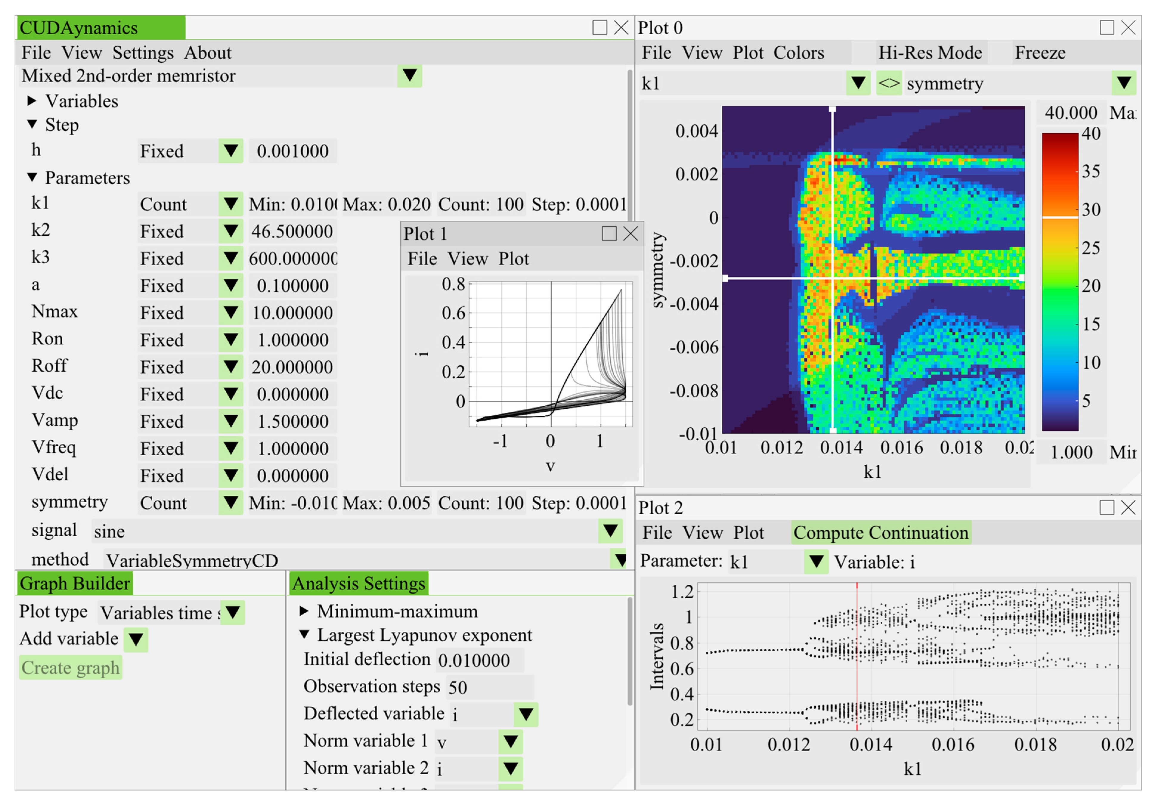
Investigating these high-dimensional nonlinear systems demands extensive numerical exploration across multidimensional parameter spaces. Contemporary research increasingly relies on parallel computing architectures, particularly graphics processing units (GPUs), to accelerate the generation of bifurcation diagrams, Lyapunov exponent maps, and synchronization thresholds [32,33,34,35,36]. These workflows are increasingly integrated for the rapid and secure handling of large data sets [37]. Complementary to high-throughput simulation, recent advances in intelligent monitoring and fractional-order multi-rate data fusion provide robust frameworks for real-time state estimation and uncertainty correction in complex nonlinear systems [38]. Integrating such methodological concepts into the analysis of memristive dynamics represents a promising direction for bridging numerical exploration with experimental validation. Complementary to high-throughput simulation, recent advances in intelligent monitoring and fractional-order multi-rate data fusion provide robust frameworks for real-time state estimation and uncertainty correction in complex nonlinear systems [38,39,40,41]. Integrating such methodological concepts into the analysis of memristive dynamics represents a promising direction for bridging numerical exploration with experimental validation. However, existing computational tools are predominantly designed for static, batch-processing workflows and rarely support real-time, interactive parameter exploration [32,42]. This paper introduces CUDAynamics, a computational framework developed for interactive analysis of chaotic and multistable dynamical systems. The platform employs a hybrid parallelization strategy, integrating NVIDIA’s Compute Unified Device Architecture (CUDA) with Open Multi-Processing (OpenMP) to achieve high-throughput numerical simulations. This computational foundation enables rapid exploration of parameter spaces, thereby accelerating hypothesis testing and dynamical regime identification in nonlinear models. User interaction is facilitated through a responsive, immediate-mode graphical interface built upon the Dear ImGui and ImPlot libraries. By decoupling interface rendering from background numerical computations, the system allows researchers to dynamically modify system parameters, initial conditions, and model topologies. In addition to a diverse built-in library of nonlinear systems, CUDAynamics incorporates several analysis tools employing the program’s parallel computational framework, such as the calculation of the largest Lyapunov exponent, periodicity and lifetime of chaotic transients. Visual outputs, including time series, phase portraits, bifurcation diagrams, and heatmaps, are updated continuously, providing researchers with an intuitive platform for exploring nonlinear phenomena. Visual overview of the suite’s graphical user interface can be found in Appendix A. The software supports both rapid exploratory modeling and high-resolution, publication-quality diagram generation, all within a unified, user-friendly framework.
The primary objective of this study is to demonstrate the research utility of CUDAynamics through a systematic investigation of nonlinear dynamics in a second-order memristive system, incorporating capacitive effects that account for parasitic charge accumulation in physical devices [19]. The computational framework and associated numerical experiments were developed as part of an applied research project focused on the nonlinear circuit dynamics. The CUDAynamics program is publicly available at: https://github.com/solawk/cudaynamics, (accessed on 1 May 2026). Microsoft Visual Studio 2022 and CUDA Toolkit 12.6.2 constitute the prerequisite dependencies for compiling the source code.
The main contributions of the study are as follows:
  • An open-source, GPU-accelerated computational environment (CUDAynamics) is introduced, featuring a responsive immediate-mode graphical interface that enables interactive, real-time navigation through high-dimensional parameter spaces of nonlinear systems.
  • Leveraging this platform, a comprehensive numerical analysis of a second-order memristive system incorporating parasitic capacitance is conducted under sinusoidal, triangular, and square-wave excitations. This reveals the precise parameter configurations and waveform-dependent sensitivities under which deterministic chaos and superperiodic regimes emerge.
  • A new finite difference scheme is implemented for the memristor using a composition diagonal method with variable symmetry (VSCD). Compared to conventional explicit schemes, it demonstrates enhanced numerical stability and introduces a tunable symmetry parameter that acts as an additional bifurcation control.
To clarify the narrative focus, the central contribution of this work is the development and validation of CUDAynamics as a scalable research tool. The memristor simulation, numerical scheme comparison, and chaos analysis constitute an applied case study that demonstrates the software’s capacity to resolve complex dynamical phenomena while providing new physical insights into waveform-driven chaotization.
The remainder of this paper is organized as follows. In Section 2, the mathematical formulation of the second-order memristive system is presented, alongside the numerical integration strategies in CUDAynamics. In Section 3, the computational results are detailed, including phase-space trajectory visualizations, and comprehensive bifurcation and stability analyses under sinusoidal, triangular, and square-wave excitations. In Section 4, the physical implications of the observed dynamical regimes are discussed and current methodological limitations are examined. Finally, Section 5 concludes the paper by summarizing the key contributions and outlining future directions for advanced nonlinear system identification.

2. Materials and Methods

We consider a second-order memristive system that includes an internal state variable x, ranging from 0 to 1 and describing the internal channel formation, and a state variable n that incorporates capacitance into the simple memristor model. The original set of equations of the studied second-order mixed system is as follows [19]:
V ( t ) = R ( x ) I ( t ) + Δ V ( x , n ) d x d t = k 2 f w ( x ) I ( t ) d n d t = k 3 f v ( n ) I ( t )
where V(t) is the input voltage, I(t) is the current passing through the memristor, R(x) = RON x + ROFF(1 − x) is the resistance of the memristor, with RON and ROFF being resistances in states 1 and 0, respectively, and ΔV(x, N) is the function of lumped capacitive effects [19]:
Δ V ( x , n ) = k 1 n x + a ,
fν(N) is the capture function [19]:
f v ( n ) = 1 n n max , n n max , n max 0 , n n max , n max ,
k1, k2, k3, a and nmax are constants.
To implement and simulate the mixed second-order memristive system in CUDAynamics, we rewrite the model’s equations into the following:
I = V k 1 n x + a R O N x + R O F F 1 x d x d t = k 2 I x = 0 ,    x < 0 1 ,    x > 1 d n d t = k 3 1 n n max , n n max , n max 0 , n n max , n max
It is important to note that in the original equations [19] a window function fw is present. It equals 1 when x is within the range [0, 1] and equals 0 otherwise. However, since the value of x is limited to this interval by definition, the function degenerates to a constant 1 and hence can be removed from the equation. If the domain of the state variable x is not limited by the range [0, 1] and the window function is present, then dx/dt becomes zero as soon as variable x leaves the interval. This completely stops the dynamics of the variable x due to lack of additive terms in the right-hand side of its differential equation.
The numerical implementation of the mixed second-order memristive model within the CUDAynamics framework, employing a finite difference scheme to solve Equation (4), is provided in Appendix A.
The stability properties and bifurcation behavior of composition methods with variable symmetry, including VSCD, have been rigorously characterized in our previous works [43,44]. These studies establish that the symmetry parameter acts as a controlled, structure-preserving perturbation: it can induce or suppress multistability without compromising the qualitative dynamics of the underlying continuous system. Table 1 summarizes the key qualities of the VSCD method in comparison with established numerical integration schemes: explicit and implicit Euler methods (EE and IE), explicit and implicit midpoint methods (EMP and IMP), as well as the Runge–Kutta method of fourth order (RK4). The computational cost per integration step is quantified by the number of evaluations of the right-hand side (RHS) function of the underlying system of ordinary differential equations required by a numerical method.
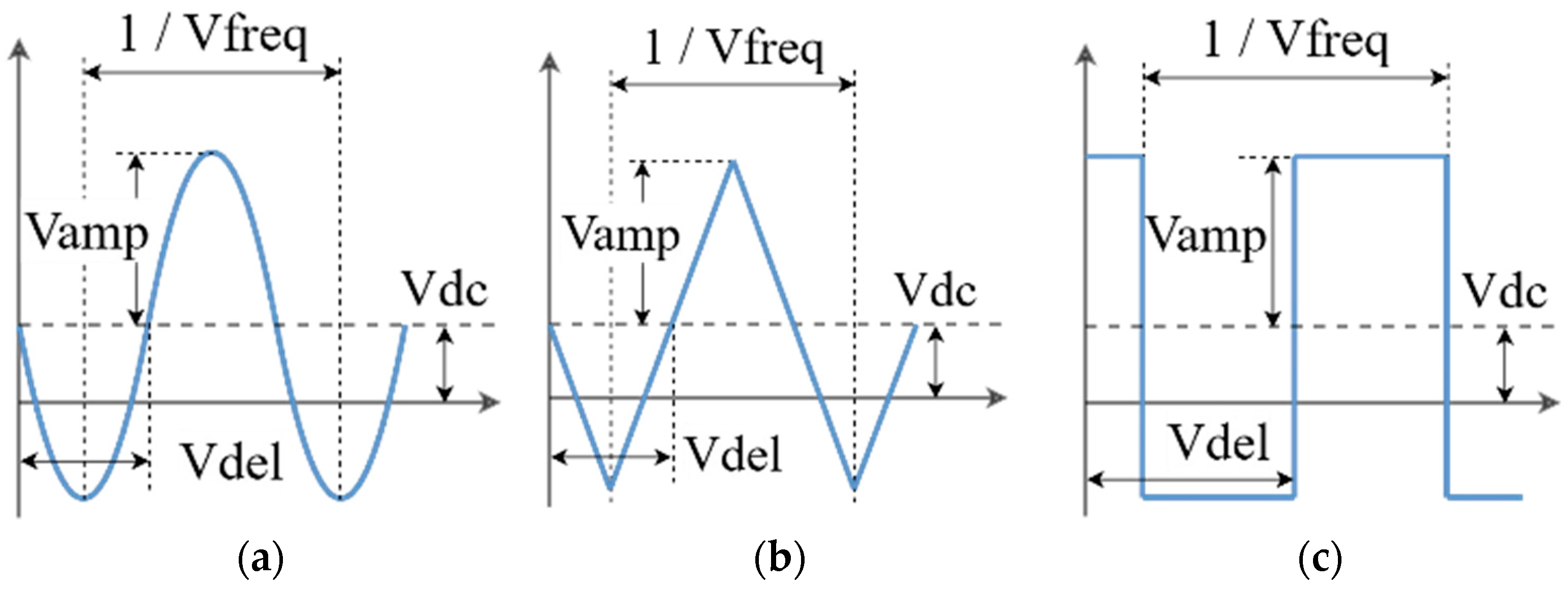
To achieve higher efficiency and robustness of the simulations, we used several numerical integration methods of higher order than the explicit Euler’s method employed in the original paper [19], including the RK4 method, the EMP method, and the VSCD method [44], which underlies the further presented simulation results. The distinctive feature of the latter method is that it consists of two adjoint parts: the first is a semi-explicit adjoint part, and the second is a diagonally implicit adjoint part (solved by two simple iterations). When the symmetry parameter is set to zero, which corresponds to midpoint evaluation over the integration step, the VSCD method falls within the class of symmetric integrators [46]. In addition to the sinusoidal input signal, which was the only one the memristive system has been previously tested with [19], we introduce a triangle wave and a square wave as new possible input signals, see Figure 1.
The considered system is available in the suite’s library under the name “Mixed 2nd-order memristor”. The finite difference schemes in CUDAynaemics are implemented as C++ compute kernels conforming to the CUDA C++ standard. Variables V()/Vnext(), parameters P(), and step-size H are batched in contiguous memory, with dedicated macros provided for efficient data access. The numb macro substitution enables arithmetic operations in either single- or double-precision floating-point formats. These kernels enable seamless execution via both CUDA and OpenMP, eliminating redundant code development without adding computational overhead.
The computational architecture of the CUDAynamics framework is built upon batched data processing via memory buffers. In interactive mode, the system employs a double-buffering strategy, wherein two buffers are computed alternately to enable continuous visual output without interruption. The size of the buffers is usually a compromise between data transfer overhead costs and memory capacity of the computing device. The suite possesses an immediate mode graphical user interface, capable of displaying multiple diagram types interconnected with each other. For example, initial value or parameter configurations can be swept through in a heatmap, updating the phase-space plots, time series and bifurcation diagrams accordingly. Trajectories in a phase-space plot can be assigned colors from a heatmap, both in the single trajectory “orbit” mode and in the trajectory ensemble “particle” mode. The whole suite works and updates together in real time, providing the tools for efficient iterative research.
For extended temporal analyses, CUDAynamics offers a high-resolution (Hi-Res) computational mode that optimizes resource utilization by disabling trajectory data transfer, thereby substantially reducing memory usage and execution time. The computational workload is partitioned into manageable chunks to facilitate scalable processing. As implied by its designation, this mode is specifically designed for the generation of high-resolution phase- and parameter-space heatmap diagrams. Furthermore, CUDAynamics supports command-line interface (CLI) execution for individual Hi-Res tasks, enabling efficient batch processing of multiple long-term simulations without manual intervention.
The largest Lyapunov exponent, serving as an indicator of chaotic behavior in the trajectory, is calculated in CUDAynamics via Wolf’s method [47,48]. The neighboring trajectory is created by displacing the original along the selected axis and is simulated alongside it. We have modified the algorithm by measuring the divergence/convergence rate for fixed time periods and resetting the distance between the trajectory points each time. This approach increased the robustness of the algorithm, implemented within the architecture of the simulation suite.

3. Results

The numerical experiments reported in this section were conducted using the CUDAynamics software suite on a workstation operating under Windows 11 Pro. The experimental platform comprised an Intel Core i7-13700K processor (16 cores, 24 threads, 5.4 GHz maximum turbo frequency), 32 GB of DDR5-6000 system memory, and an NVIDIA GeForce RTX 4070 GPU equipped with 12 GB of GDDR6X VRAM and 5888 CUDA cores.
This section is organized as follows: first, we validate the replication of [19] using the VSCD method; second, we demonstrate the interactive visualization capabilities of CUDAynamics; third, we present original results on waveform-dependent dynamics and symmetry-parameter bifurcations.
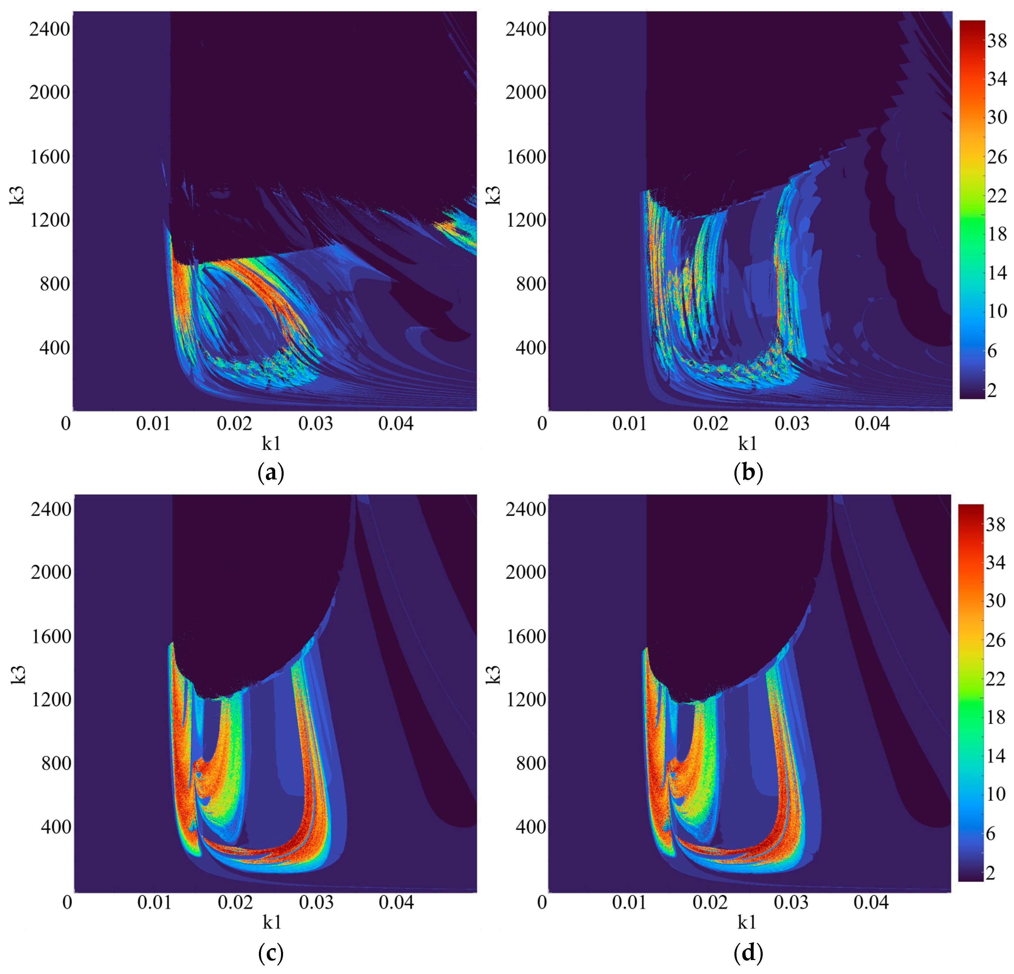
The second-order capacitive memristor model and its chaotic behavior under sinusoidal excitation were initially reported in [19], our work replicates these results using higher-order integration schemes to confirm their numerical robustness. Initial conditions for all variables are values of 0. Most of the parameter values have been provided in the paper [19]: a = 0.1, nmax = 10, k2 = 46.5. The exact resistance values ROFF and RON have not been listed in the source, so the values have been iteratively estimated to match the resulting figures with identical parameter sweep settings. We therefore assume the missing values ROFF = 1 and RON = 20 by default, as we have managed to compute a qualitatively similar period diagram with these values. Parameter k1 was swept from 0 to 0.05 and parameter k3 was swept from 0 to 2500. VSCD method was used with a step size h = 0.001 in double precision by default. CUDAynamics is currently limited to using a fixed time step. While this is a noticeable limitation, it did not impede the conducted research and insight gain. While adaptive-step methods are superior for minimizing local truncation error in single-trajectory simulations, they introduce variable temporal resolution that complicates the consistent computation of global dynamical indicators (e.g., Lyapunov exponents, periodicity classification) across massive parameter grids. For the systematic mapping of bifurcation structures, uniform discretization ensures that the distribution of the computed points in parameter space corresponds to a consistent computational effort and temporal sampling, which is critical for reproducible heatmap generation. The variable for feature extraction is the current I, the neighborhood size is chosen as ε = 0.1. Simulation time consisted of 800,000 transient steps and 500,000 steps subjected to analysis. In Figure 2a comparison is presented between the simulation results with different numerical schemes. As can be seen, at an integration step-size h = 0.01, second-order methods lose stability. However, unlike EMP, the VSCD method preserves the proportions of the dynamical mode regions much better. At an integration step-size h = 0.001, the VSCD result is almost indistinguishable from the reference RK4 method.
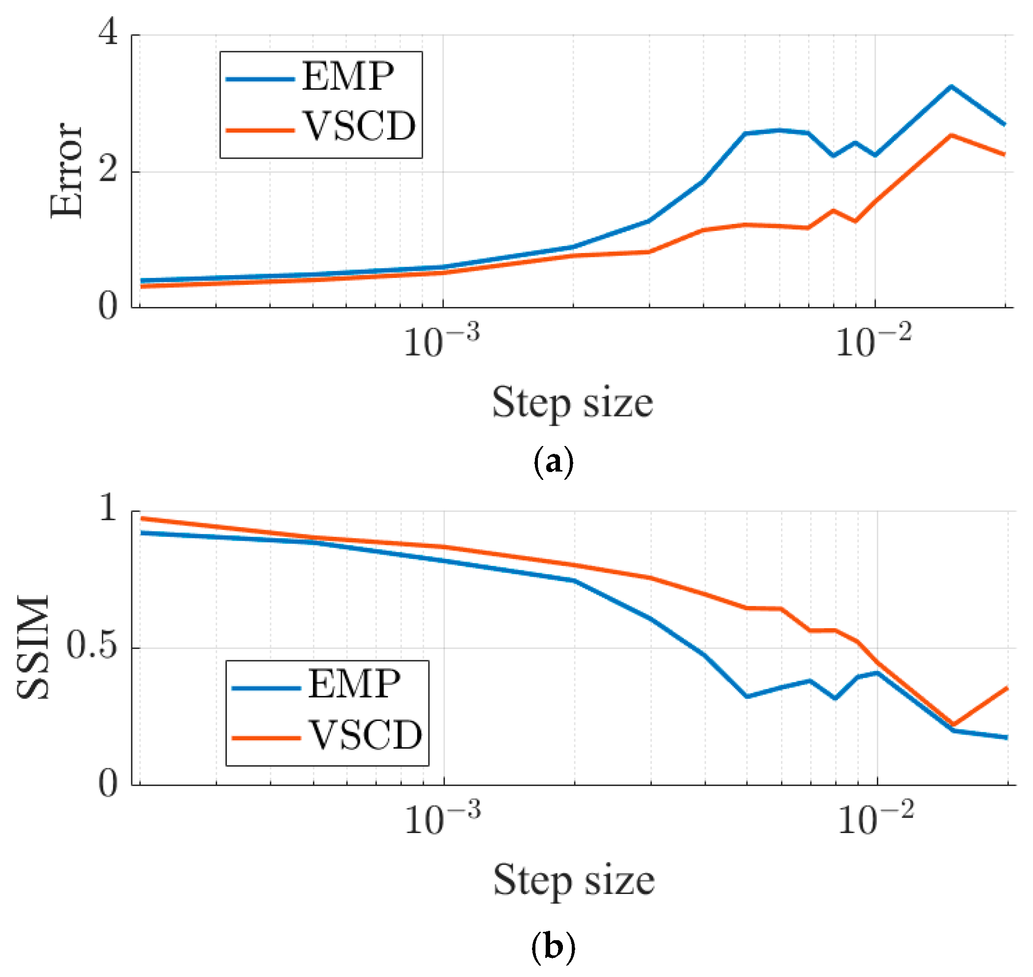
Comparative accuracy analysis, results of which are provided in Figure 3, demonstrate an advantage of the VSCD method over EMP with the same timestep. The experiment was carried out by constructing diagrams with a resolution of 100 × 100. In Figure 3a, the error was derived as the sum of the difference in the periodicity values of the solution under consideration (VSCD and EMP) compared to the reference RK4 with the step-size h = 0.0001, divided by the diagram resolution. A stability loss is noticeable for the EMP method, unlike VSCD, which maintains accuracy over larger step-sizes. It is especially notable in the case of the structural similarity index measure [49] (SSIM) comparison in Figure 3b, where values closer to 1 are better. With the same accuracy (error e = 0.5165) the solution is achieved by the VSCD method with the step-size h = 0.001 and by the EMP method with the step size h = 0.005825. In CUDAynamics on a computer with the specified configuration, the runtime for constructing the corresponding periodicity diagram using the VSCD method is 16.07 s, and using the EMP method it is 17.51 s. Thus, the finite-difference scheme of the VSCD method is more efficient and also has additional symmetry parameterization.
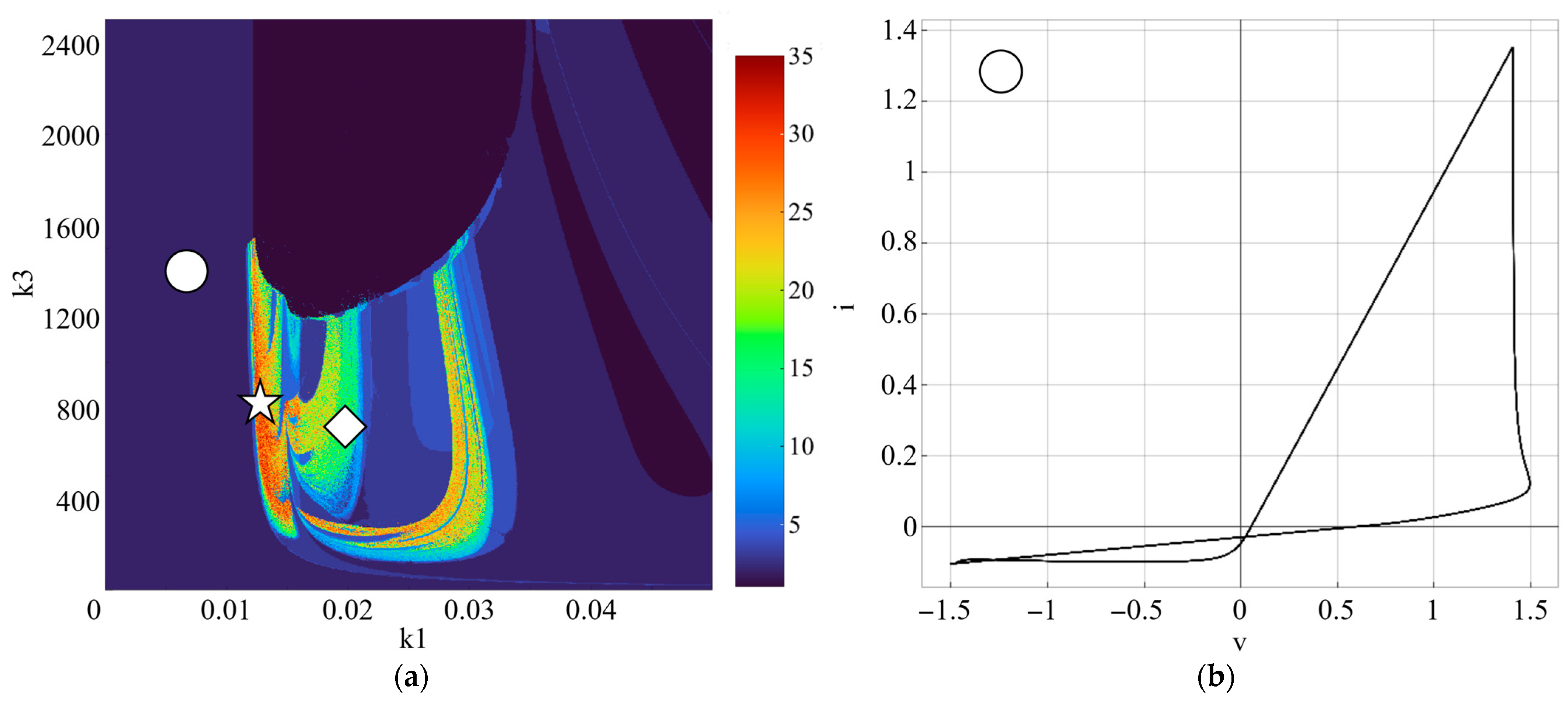
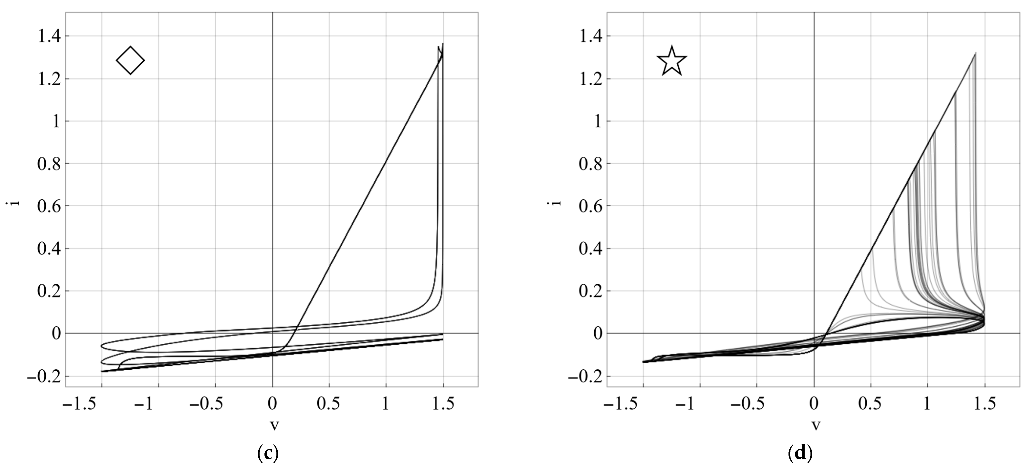
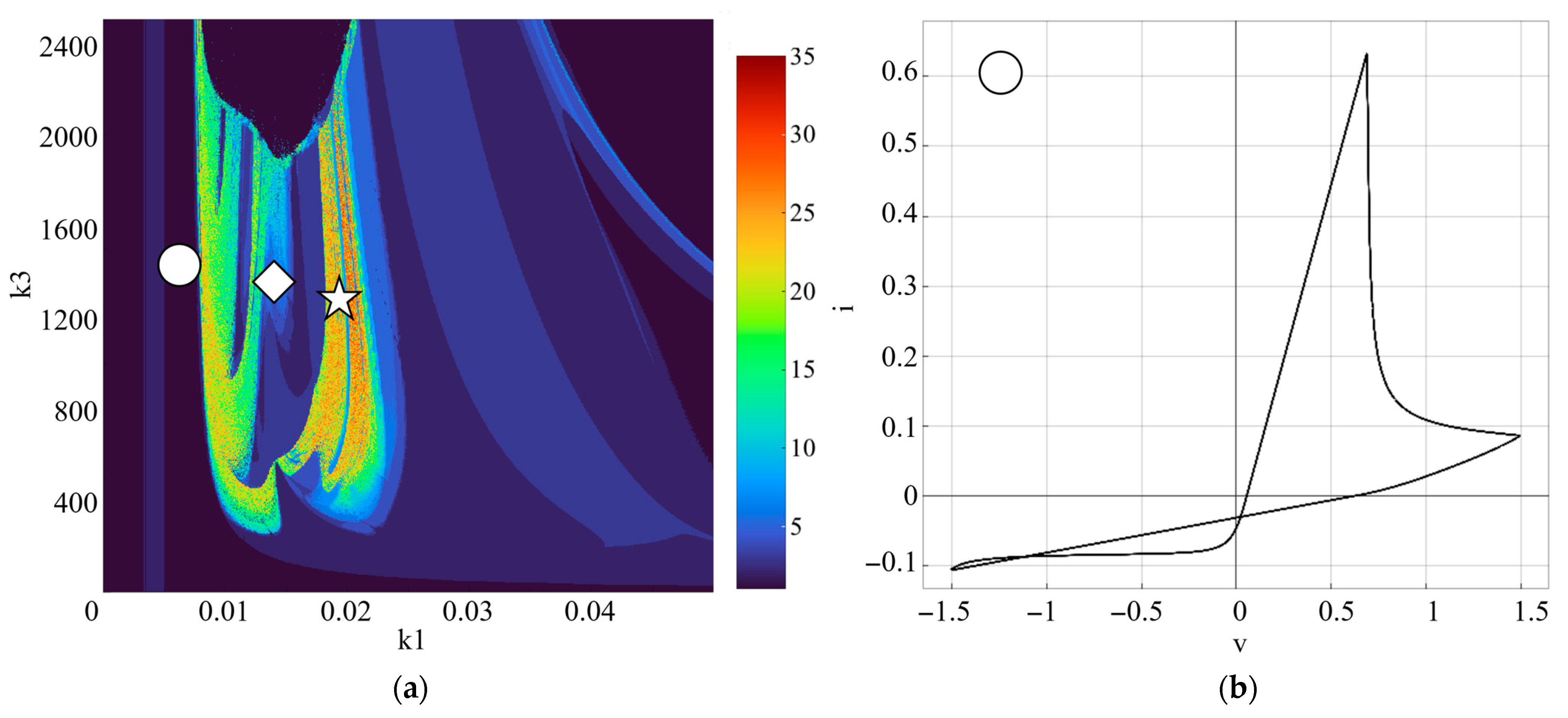
By enabling instantaneous rendering of phase-space trajectories, CUDAynamics provides visual means to track the emergence and development of the hysteresis loop in the memristor’s I-V curve, as demonstrated in Figure 4.
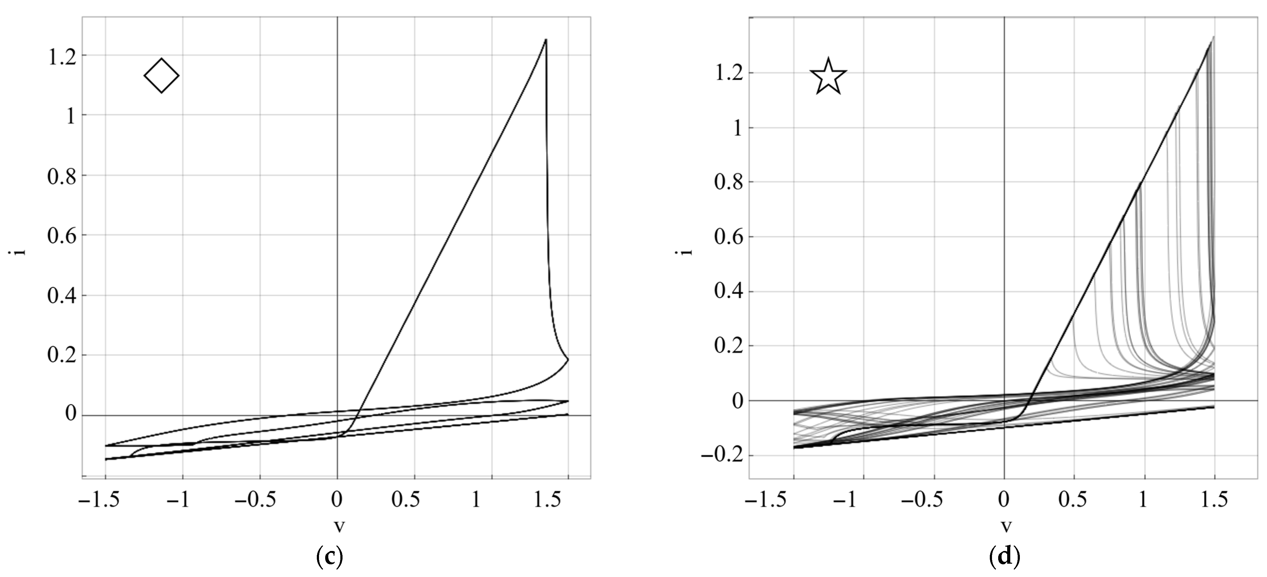
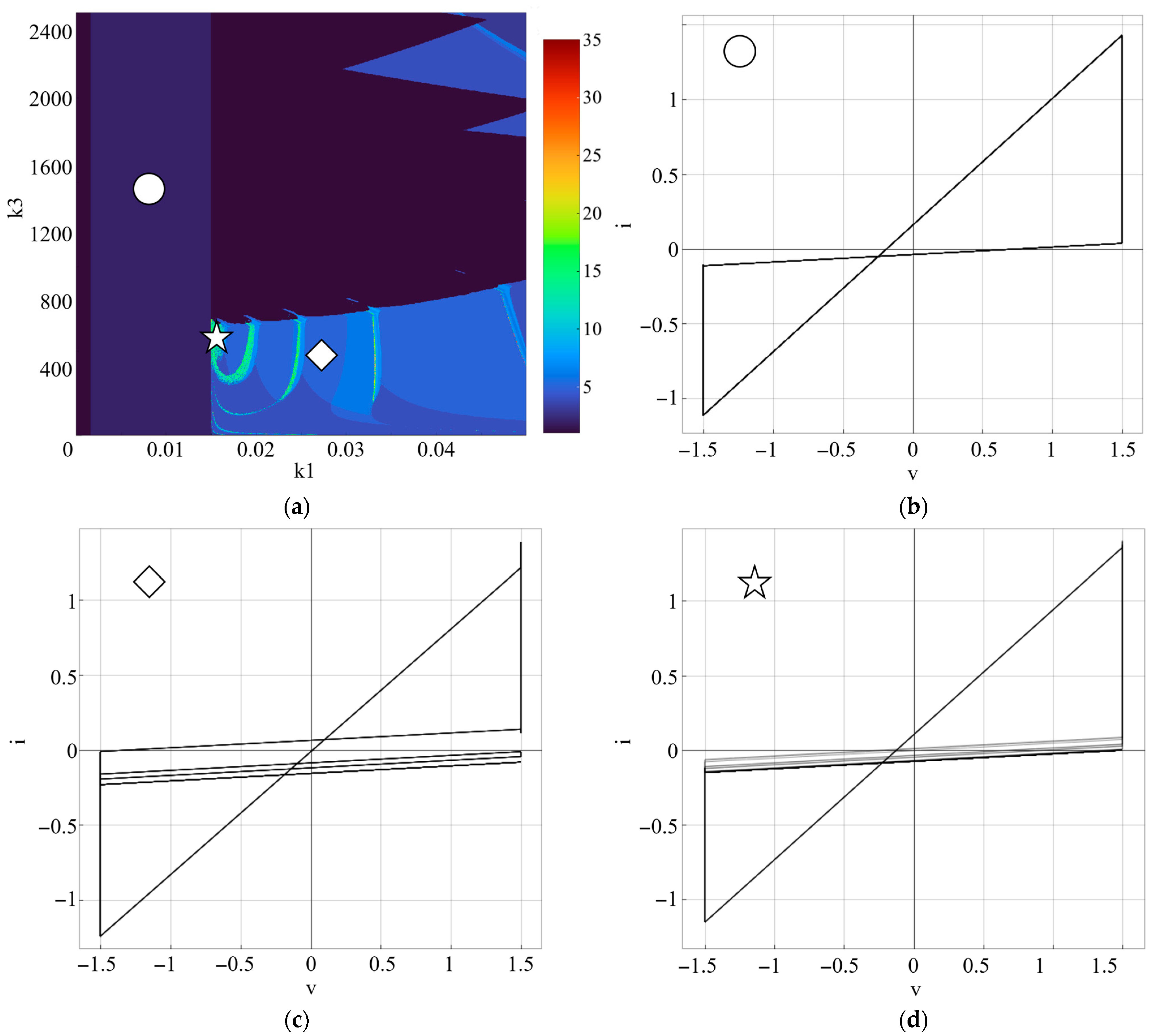
Numerical simulations featuring triangular and square excitation waveforms were conducted using equivalent parameter sets. The resulting diagrams are presented in Figure 5 and Figure 6.
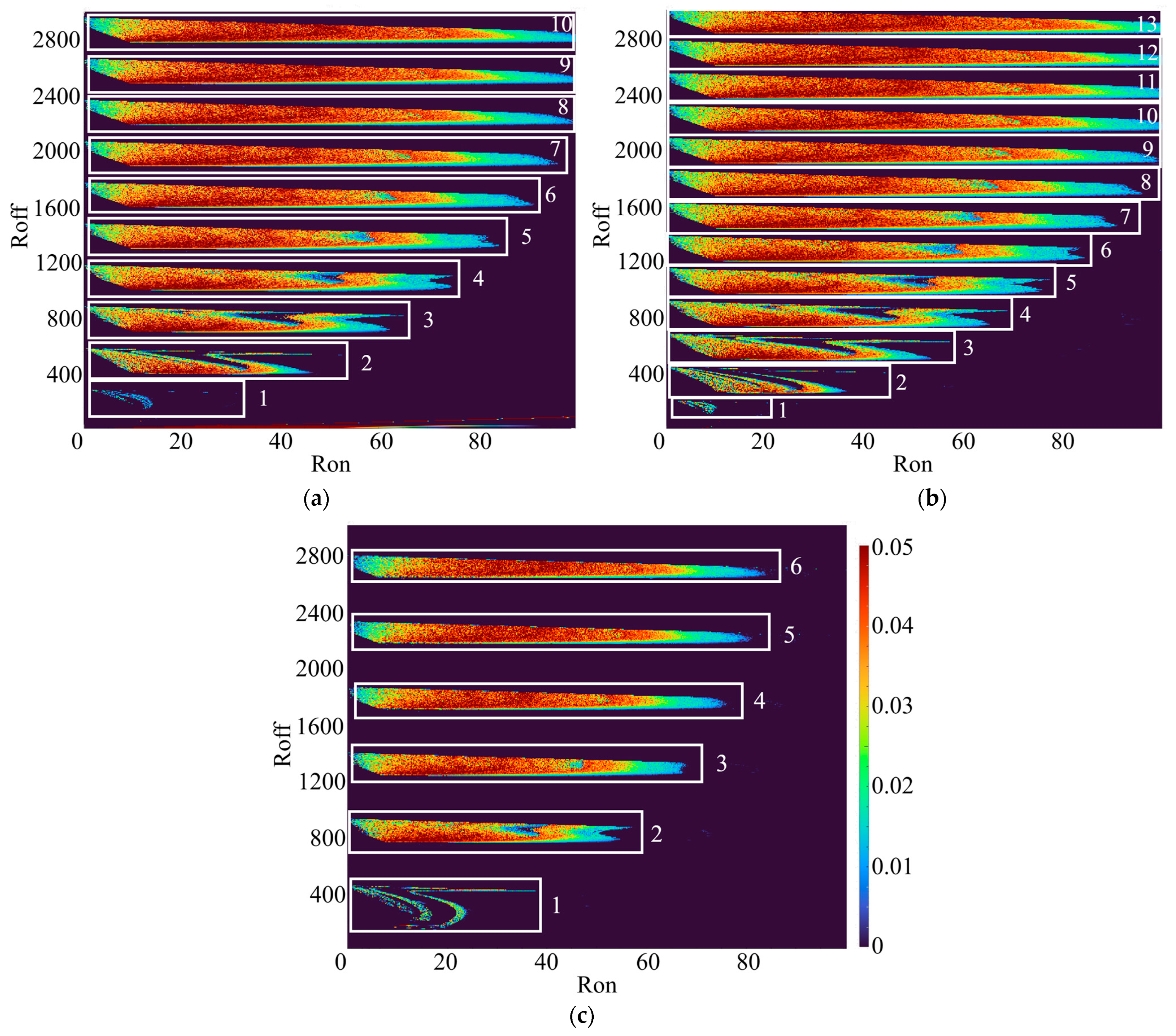
The location and extent of the memristor’s chaotic behavior regions in the resistances RON and ROFF parameter space depend on the input signal’s amplitude Vamp, as demonstrated in the largest Lyapunov exponent diagram in Figure 7. To calculate the exponent, the value of variable x is displaced by 10−5 and the neighboring trajectory is simulated for 300 steps before every divergence/convergence rate measurement and the displacement distance reset. To measure the distance between the trajectories in the phase-space the variable values n and x are used. Consistent with theoretical expectations, increased resistance levels require a correspondingly higher excitation amplitude to trigger resistive switching. In the case of amplitude value variation, the location of the chaotic region depends linearly on the resistance value ROFF, but depends nonlinearly on the value RON. As amplitude is increased, the shape of this region is compressed along the ROFF parameter axis. At low Vamp values, the chaotic region exhibits a comparable morphology across all signal types; however, as Vamp increases, this region progressively narrows under square-wave excitation.
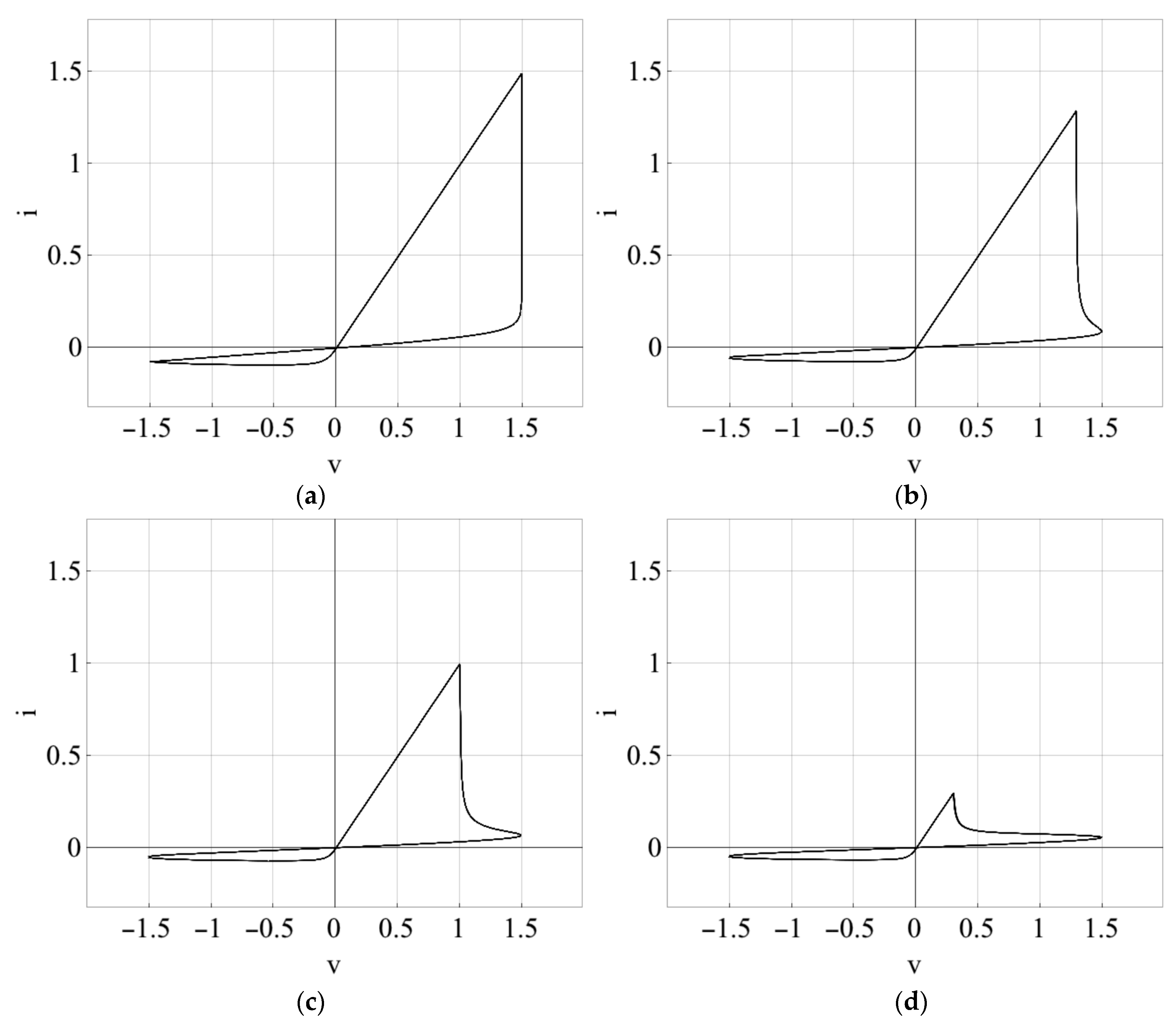
Within the investigated parameter space, high-periodicity regimes, termed “superperiodicity” [19], coexist with chaotic dynamics. Additionally, the relative ROFF modulates the prominence of the S-shaped negative differential resistance (NDR) region observed during the memristor’s transition from the high-resistance to the low-resistance state, as illustrated in Figure 8.
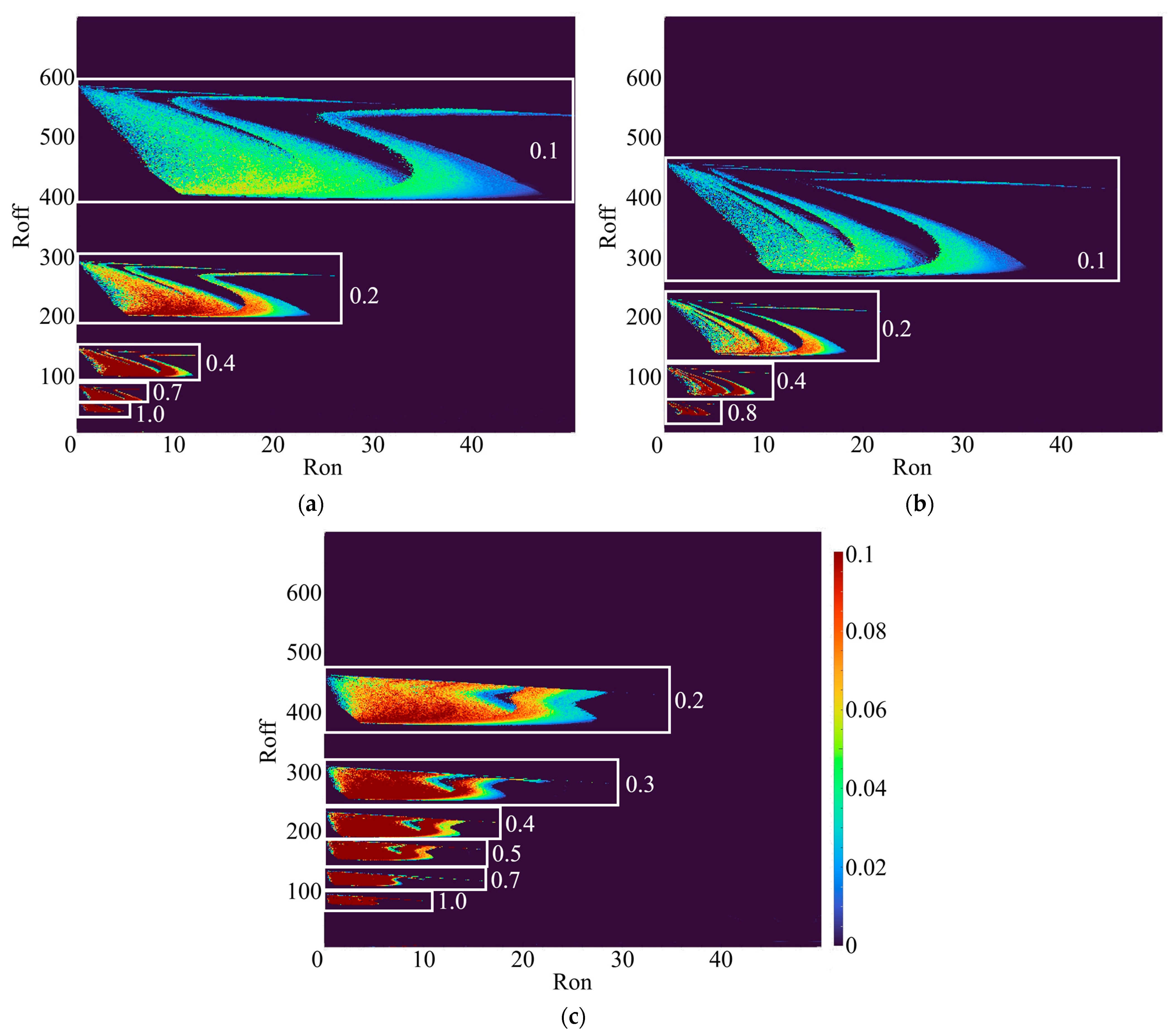
Decreasing the input signal frequency Vfreq expands the chaotic regimes in the memristor’s parameter space, as shown in Figure 9. This expansion follows a linear trend along both the ROFF and RON axes. Moreover, the morphology of these chaotic regions remains qualitatively similar under sine and triangular excitation, whereas square-wave forcing yields distinctly different structures.
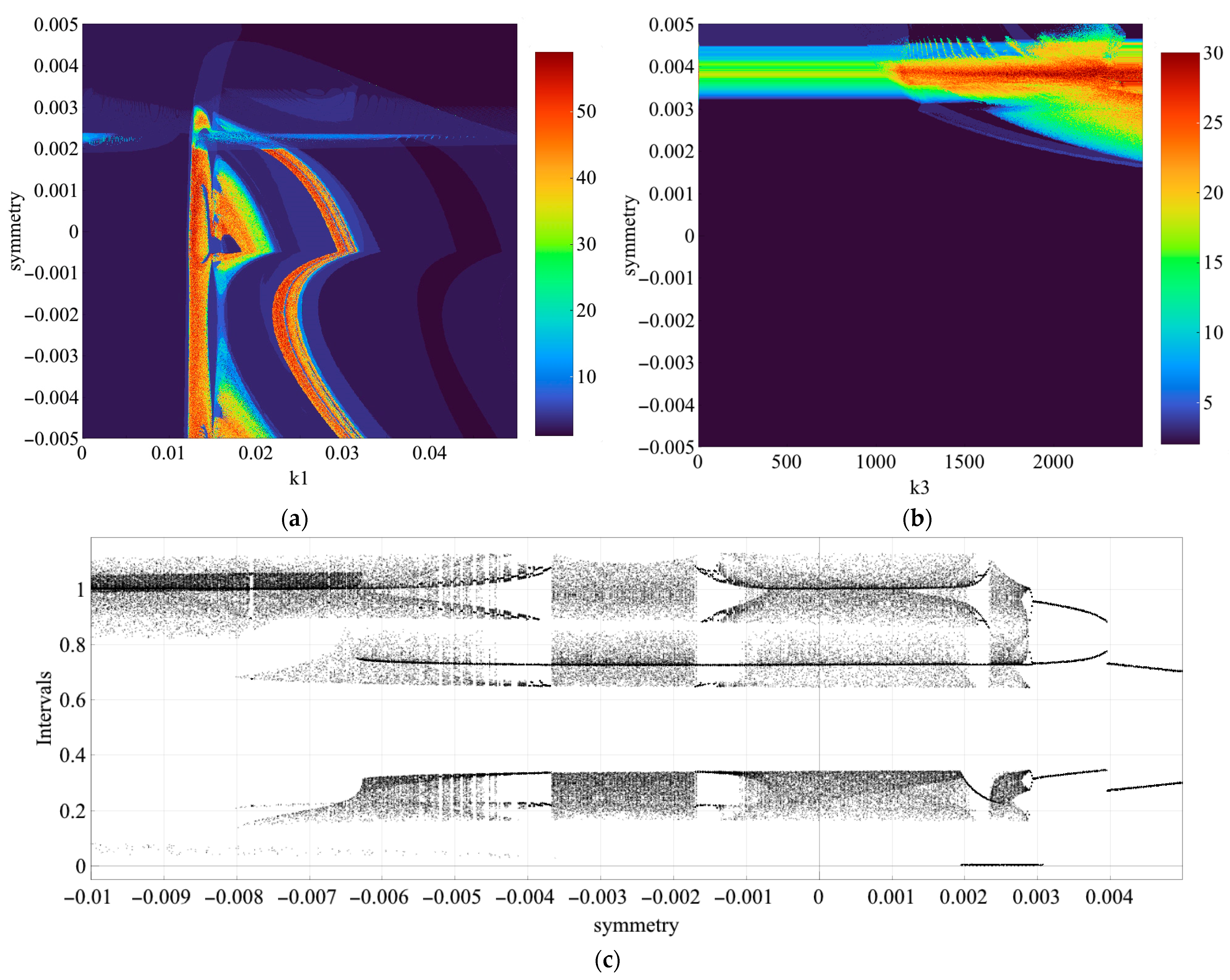
The results presented in Figure 10 confirm that the introduced symmetry parameter inherent to the VSCD framework exhibits bifurcation-dependent behavior. The two-parameter diagrams show that varying the symmetry parameter nonlinearly alters dynamical regions across the entire k1 plane, but only in the positive k3 region, where it induces a transition from an initially stable periodic state to chaos. The one-dimensional diagram of the current I inter-peak intervals is intended to illustrate the bifurcation scenario with respect to the symmetry parameter.

4. Discussion

The obtained simulation results confirm the fundamental role of second-order capacitive dynamics in the emergence of complex regimes within memristive systems. Unlike first-order models, which are typically constrained to relaxation or periodic oscillations, the introduction of an additional state variable representing stored charge establishes the necessary conditions for deterministic chaos. The parasitic capacitive component effectively acts as a phase-shift mechanism, disrupting regular periodicity and driving the system into chaotic attractors. This structural transition underscores the necessity of incorporating higher-order parasitic effects into memristor modeling to accurately predict device behavior in neuromorphic and analog circuit applications.
It is important to emphasize that the dynamical regimes reported in this study were obtained through numerical simulation of the model proposed in [19]. While this model incorporates parasitic capacitive effects motivated by physical considerations [16,17,18,50], direct experimental validation against measured I-V curves of specific memristive devices falls outside the scope of the present methodological contribution. However, our research group has previously demonstrated experimental identification procedures for real memristive devices, including Knowm memristors [22] and threshold-switching selectors, using the dynamic route map approach and compact modeling techniques. The models identified in those works are already imported into CUDAynamics for hardware-calibrated simulation, establishing a clear pathway from numerical exploration to experimental verification.
The present findings demonstrate that chaotization is not a numerical artifact but an intrinsic structural property of the extended model. This conclusion is now supported by three convergent lines of evidence: (i) the consistency of dynamical regimes across integration methods of different orders and step-sizes (as shown in Figure 2), confirming numerical robustness; (ii) the preservation of chaotic attractors under variation of the symmetry parameter, in agreement with the stability theory for semi-implicit composition schemes [43]; and (iii) the theoretical framework for variable-symmetry integrators [44], which establishes that the additional capacitive state variable n introduces the minimal phase-space dimensionality required for Shilnikov-type homoclinic bifurcations in memristive systems [19].
Furthermore, this study reveals that the geometry of chaotic parameter regions is highly sensitive to the excitation waveform. Continuous signals, such as sinusoidal and triangular inputs, yield topologically similar bifurcation structures due to their smooth derivatives and absence of discontinuities. Conversely, square-wave excitation introduces abrupt voltage transitions that amplify nonlinear responses and compress the spatial extent of chaotic attractors. This waveform-dependent behavior has direct implications for both analog signal processing and digital switching architectures.
Aside from replicating and clarifying the simulation results from the work [19] with a numerical integration method of higher order, the results hold substantial practical value for hardware design. The identification of stable chaotic regimes facilitates the development of hardware-based pseudorandom number generators, where memristive oscillators offer superior integration density and lower power consumption compared to conventional complementary metal-oxide-semiconductor (CMOS) implementations. Additionally, the persistence of chaotic dynamics under square-wave inputs highlights a critical design consideration for digital memristive and neuromorphic circuits: unintended chaotization must be explicitly accounted for to ensure predictable switching and reliable memory retention. These findings provide design insights for memristive neuromorphic circuits and hardware-based cryptographic systems. While the present study establishes the computational framework and identifies waveform-dependent dynamical phenomena through high-resolution numerical analysis, subsequent work will focus on calibrating the simulated regimes against experimental data from physical memristive devices using identification methodologies developed in our prior studies [22].
The computational framework employed in this study, CUDAynamics, applies GPU-accelerated parallelization to overcome the limitations of traditional sequential simulators (e.g., simulation program with integrated circuit emphasis or SPICE), which are often ill-suited for high-dimensional parameter sweeps and real-time bifurcation analysis. By providing immediate-mode graphical feedback and enabling on-the-fly modification of system parameters, CUDAynamics transforms abstract research on nonlinear dynamics into an observable, exploratory process.
Despite these contributions, the current implementation relies on fixed-step numerical integration and lacks adaptive local error control, which may limit precision in stiff dynamical regimes. Future work will follow a three-phase implementation roadmap. First, to overcome the limitations of fixed-step integration, we will integrate an adaptive time-stepping scheme into CUDAynamics based on the variable-step modified VSCD method. A new framework will be adopted to couple a Hairer-type step-size controller with an adjustable symmetry parameter, enabling dynamic step adaptation while preserving the discrete system’s geometric and chaotic properties. Implementation will include tolerance-driven step control, local error estimation, and GPU-optimized extrapolation tables to reduce computational overhead in stiff regimes. Second, experimental validation will be conducted using our established parameter-identification workflow [22]. We will acquire I-V hysteresis and transient response data from physical Knowm memristive devices under identical sinusoidal, triangular, and square-wave excitations, followed by inverse optimization to quantify deviations between simulated and measured regimes. It should be noted that the memristor model employed here assumes deterministic threshold dynamics, whereas physical devices exhibit cycle-to-cycle variability due to filamentary stochasticity [10]. While this limitation does not invalidate the structural chaos observed in the idealized model, it implies that under parameter sweeps experimental results would likely display noisy boundaries rather than sharp bifurcation curves. Third, to facilitate engineering applications, the validated discrete models will be exported as SPICE-compatible macro-models and benchmarked in hardware-in-the-loop prototypes for neuromorphic applications. Each phase will be accompanied by open-source code updates, benchmark datasets, and reproducibility documentation to ensure practical utility for the nonlinear dynamics and memristive engineering communities.

5. Conclusions

The present study demonstrates that incorporating parasitic capacitive effects into a second-order memristor model serves as a sufficient condition for the emergence of deterministic chaos and superperiodic regimes, thereby validating and extending prior numerical investigations. Through high-order numerical integration in the CUDAynamics environment, we established that the geometry and spatial extent of chaotic parameter regions are highly sensitive to the excitation waveform. While continuous sinusoidal and triangular inputs yield topologically analogous bifurcation structures, square-wave excitation compresses chaotic attractors. The GPU-accelerated parallel architecture of the suite enabled rapid, high-resolution mapping of these multidimensional parameter spaces, overcoming the computational bottlenecks inherent in traditional sequential simulators and confirming the structural, rather than numerical, nature of the observed chaotization. These results yield essential design guidelines for memristive neuromorphic circuits and hardware cryptographic systems, wherein both intentional and emergent chaotic dynamics must be rigorously characterized to guarantee operational reliability.

Author Contributions

Conceptualization, D.B., V.O. and Y.B.; data curation, A.K.; formal analysis, Y.B.; funding acquisition, V.O.; investigation, A.K., M.G. and V.O.; methodology, D.B. and V.O.; project administration, D.B. and V.O.; resources, A.K., M.G. and Y.B.; software, A.K., M.G., V.O. and D.B.; supervision, D.B. and V.O.; validation, M.G. and V.O.; visualization, M.G., V.O. and Y.B.; writing—original draft, A.K., M.G. and V.O.; writing—review and editing, D.B. and Y.B. All authors have read and agreed to the published version of the manuscript.

Funding

This research was supported by the Russian Science Foundation (RSF), project № 23-79-10151.

Data Availability Statement

The CUDAynamics interactive suite presented in the study is openly available on GitHub at https://github.com/solawk/cudaynamics (accessed on 1 May 2026). Further inquiries can be directed to the corresponding authors.

Acknowledgments

Gratitude is expressed to the project team members: Timur Karimov, Kirill Shirnin, Maksim Kulagin, Petr Fedoseev, Vladislav Kholkin and Vyacheslav Rybin. Similarly, we acknowledge our students: Ivan Guitor, Ksenia Shinkar, Anastasia Karpenko, and Nikita Beliaev for their contributions to CUDAynamics development.

Conflicts of Interest

The authors declare no conflicts of interest.

Abbreviations

The following abbreviations are used in this manuscript:
CLICommand-line interface
CMOSComplementary Metal-Oxide-Semiconductor
CUDACompute Unified Device Architecture
EEExplicit Euler method
EMPExplicit midpoint method
GPUsGraphics Processing Units
HPHewlett-Packard
IEImplicit Euler method
IMPImplicit midpoint method
I-VCurrent-voltage
NDRNegative differential resistance
OpenMPOpen Multi-Processing
RHSRight-hand side function
RK4Runge–Kutta 4 method
SPICESimulation Program with Integrated Circuit Emphasis
SSIMStructural similarity index measure
VSCDVariable symmetry composition diagonal method

Appendix A

Examples of windows opened in the CUDAynamics environment are shown in Figure A1.
Figure A1. Graphical user interface of CUDAynamics, showcasing a portion of diagrams available for the memristive system research. Main window with settings and simulation controls is presented on the left; Plot 0 is a heatmap diagram example with a colormap legend and a crosshair pointing at the selected simulated trajectory; Plot 1 is a phase-space diagram example for the selected trajectory; Plot 2 is a bifurcation diagram example for the selected bifurcation parameter.
Algorithms 19 00402 g0a1
Listing A1 contains the source code of the numerical implementation of the researched model within the CUDAynamics framework.
Listing A1. Finite difference scheme implementation of the mixed second-order memristor with sinusoidal input by the variable symmetry composition diagonal method (VSCD) method in CUDAynamics.
Algorithms 19 00402 i001

References

  1. Chua, L. Memristor-The missing circuit element. IEEE Trans. Circuit Theory 1971, 18, 507–519. [Google Scholar] [CrossRef]
  2. Strukov, D.B.; Snider, G.S.; Stewart, D.R.; Williams, R.S. The missing memristor found. Nature 2008, 453, 80–83, Erratum in Nature 2009, 459, 1154. [Google Scholar] [CrossRef] [PubMed]
  3. Jo, S.H.; Chang, T.; Ebong, I.; Bhadviya, B.B.; Mazumder, P.; Lu, W. Nanoscale Memristor Device as Synapse in Neuromorphic Systems. Nano Lett. 2010, 10, 1297–1301. [Google Scholar] [CrossRef]
  4. Yang, X.; Taylor, B.; Wu, A.; Chen, Y.; Chua, L.O. Research Progress on Memristor: From Synapses to Computing Systems. IEEE Trans. Circuits Syst. I Regul. Pap. 2022, 69, 1845–1857. [Google Scholar] [CrossRef]
  5. Yuklyaevskikh, G.A.; Shvetsov, B.S.; Emelyanov, A.V.; Kulagin, V.A.; Rylkov, V.V.; Demin, V.A. Plasticity of parylene memristors: Compact phenomenological model and synaptic properties. Chaos Solitons Fractals 2025, 190, 115784. [Google Scholar] [CrossRef]
  6. Yi, W.; Tsang, K.K.; Lam, S.K.; Bai, X.; Crowell, J.A.; Flores, E.A. Biological plausibility and stochasticity in scalable VO2 active memristor neurons. Nat. Commun. 2018, 9, 4661. [Google Scholar] [CrossRef]
  7. James, A.P.; Chua, L.O. Variability-Aware Memristive Crossbars—A Tutorial. IEEE Trans. Circuits Syst. II Express Briefs 2022, 69, 2570–2574. [Google Scholar] [CrossRef]
  8. Gao, L.; Ren, Q.; Sun, J.; Han, S.-T.; Zhou, Y. Memristor modeling: Challenges in theories, simulations, and device variability. J. Mater. Chem. C Mater. 2021, 9, 16859–16884. [Google Scholar] [CrossRef]
  9. Joglekar, Y.N.; Wolf, S.J. The elusive memristor: Properties of basic electrical circuits. Eur. J. Phys. 2009, 30, 661–675. [Google Scholar] [CrossRef]
  10. Kvatinsky, S.; Wald, N.; Satat, G.; Kolodny, A.; Weiser, U.C.; Friedman, E.G. MRL—Memristor Ratioed Logic. In 2012 13th International Workshop on Cellular Nanoscale Networks and Their Applications; IEEE: New York, NY, USA, 2012; pp. 1–6. [Google Scholar] [CrossRef]
  11. Roldán, J.B.; Miranda, E.; Maldonado, D.; Mikhaylov, A.N.; Agudov, N.V.; Dubkov, A.A.; Koryazhkina, M.N.; González, M.B.; Villena, M.A.; Poblador, S.; et al. Variability in Resistive Memories. Adv. Intell. Syst. 2023, 5, 202200338. [Google Scholar] [CrossRef]
  12. Acal, C.; Maldonado, D.; Aguilera, A.M.; Zhu, K.; Lanza, M.; Roldán, J.B. Holistic Variability Analysis in Resistive Switching Memories Using a Two-Dimensional Variability Coefficient. ACS Appl. Mater. Interfaces 2023, 15, 19102–19110. [Google Scholar] [CrossRef] [PubMed]
  13. Maldonado, D.; Aldana, S.; González, M.B.; Jiménez-Molinos, F.; Ibáñez, M.J.; Barrera, D.; Campabadal, F.; Roldán, J.B. Variability estimation in resistive switching devices, a numerical and kinetic Monte Carlo perspective. Microelectron. Eng. 2022, 257, 111736. [Google Scholar] [CrossRef]
  14. Glukhov, A.; Bridarolli, D.; Ricci, S.; Li, R.; Shreya, S.; Farkhani, H.; Moradi, F.; Ielmini, D. Compact Modeling of Resistive Switching Memory (RRAM) with Voltage and Temperature Dependences. In 2023 IEEE Nanotechnology Materials and Devices Conference (NMDC); IEEE: New York, NY, USA, 2023; pp. 793–797. [Google Scholar] [CrossRef]
  15. Son, S.; Bende, A.; Schön, D.; Ahmad, R.W.; Nielinger, D.; Rana, V.; Menzel, S. A Comprehensive Compact Model for Multilevel Switching in TaOx-Based Memristive 1T-1R Cells. IEEE Access 2025, 13, 127280–127291. [Google Scholar] [CrossRef]
  16. Yang, J.J.; Strukov, D.B.; Stewart, D.R. Memristive devices for computing. Nat. Nanotechnol. 2013, 8, 13–24. [Google Scholar] [CrossRef] [PubMed]
  17. Itoh, M.; Chua, L.O. Parasitic Effects on Memristor Dynamics. Int. J. Bifurc. Chaos 2016, 26, 1630014. [Google Scholar] [CrossRef]
  18. Shen, Y.; Wang, G.; Liang, Y.; Yu, S.; Iu, H.H.-C. Parasitic Memcapacitor Effects on HP TiO2 Memristor Dynamics. IEEE Access 2019, 7, 59825–59831. [Google Scholar] [CrossRef]
  19. Guseinov, D.V.; Matyushkin, I.V.; Chernyaev, N.V.; Mikhaylov, A.N.; Pershin, Y.V. Capacitive effects can make memristors chaotic. Chaos Solitons Fractals 2021, 144, 110699. [Google Scholar] [CrossRef]
  20. Singh, J.; Sharma, S.K.; Raj, B. Investigation of Inherent Capacitive Effects in Linear Memristor Model. Silicon 2021, 13, 3423–3430. [Google Scholar] [CrossRef]
  21. Yarragolla, S.; Hemke, T.; Jalled, F.; Gergs, T.; Trieschmann, J.; Arul, T.; Mussenbrock, T. Identifying and understanding the nonlinear behavior of memristive devices. Sci. Rep. 2024, 14, 31633. [Google Scholar] [CrossRef]
  22. Ostrovskii, V.; Fedoseev, P.; Bobrova, Y.; Butusov, D. Structural and Parametric Identification of Knowm Memristors. Nanomaterials 2021, 12, 63. [Google Scholar] [CrossRef] [PubMed]
  23. Corinto, F.; Ascoli, A.; Gilli, M. Nonlinear Dynamics of Memristor Oscillators. IEEE Trans. Circuits Syst. I Regul. Pap. 2011, 58, 1323–1336. [Google Scholar] [CrossRef]
  24. Buscarino, A.; Fortuna, L.; Frasca, M.; Gambuzza, L.V. A chaotic circuit based on Hewlett-Packard memristor. Chaos Interdiscip. J. Nonlinear Sci. 2012, 22, 023136. [Google Scholar] [CrossRef]
  25. Bao, B.C.; Bao, H.; Wang, N.; Chen, M.; Xu, Q. Hidden extreme multistability in memristive hyperchaotic system. Chaos Solitons Fractals 2017, 94, 102–111. [Google Scholar] [CrossRef]
  26. Chen, S.; Ding, D.; Yang, Z. Multistability and Hidden Attractors in a Fractional-Order Memristive Tabu Learning Neuron Model and Its Medical Image Encryption. In 2023 IEEE International Conference on Memristive Computing and Applications (ICMCA); IEEE: New York, NY, USA, 2023; pp. 1–5. [Google Scholar] [CrossRef]
  27. Yuan, L.-G.; Yang, Q.-G. Parameter identification and synchronization of fractional-order chaotic systems. Commun. Nonlinear Sci. Numer. Simul. 2012, 17, 305–316. [Google Scholar] [CrossRef]
  28. Deng, Y.; Zhang, S.; Yuan, F.; Li, Y.; Wang, G. Reservoir computing system using discrete memristor for chaotic temporal signal processing. Chaos Solitons Fractals 2025, 194, 116230. [Google Scholar] [CrossRef]
  29. Ibrahim, H.M.; Abunahla, H.; Mohammad, B.; AlKhzaimi, H. Memristor-based PUF for lightweight cryptographic randomness. Sci. Rep. 2022, 12, 8633. [Google Scholar] [CrossRef] [PubMed]
  30. Singh, S.; Fan, X.; Prasad, A.K.; Jia, L.; Nag, A.; Balasubramonian, R.; Bojnordi, M.N.; Shi, E. XCRYPT: Accelerating Lattice-Based Cryptography with Memristor Crossbar Arrays. IEEE Micro 2023, 43, 45–54. [Google Scholar] [CrossRef]
  31. Stojanovski, T.; Kocarev, L. Chaos-based random number generators-part I: Analysis. IEEE Trans. Circuits Syst. I Fundam. Theory Appl. 2001, 48, 281–288. [Google Scholar] [CrossRef]
  32. Fazanaro, F.I.; Soriano, D.C.; Suyama, R.; Madrid, M.K.; de Oliveira, J.R.; Muñoz, I.B.; Attux, R. Numerical characterization of nonlinear dynamical systems using parallel computing: The role of GPUs approach. Commun. Nonlinear Sci. Numer. Simul. 2016, 37, 143–162. [Google Scholar] [CrossRef]
  33. Simpson, B.G.; Zhu, M.; Seki, A.; Scott, M. Challenges in GPU-Accelerated Nonlinear Dynamic Analysis for Structural Systems. J. Struct. Eng. 2023, 149, 04022253. [Google Scholar] [CrossRef]
  34. Rybin, V.; Butusov, D.; Shirnin, K.; Ostrovskii, V. Revealing Hidden Features of Chaotic Systems Using High-Performance Bifurcation Analysis Tools Based on CUDA Technology. Int. J. Bifurc. Chaos 2024, 34, 2450134. [Google Scholar] [CrossRef]
  35. Rybin, V.; Babkin, I.; Ostrovskii, V.; Gerasimov, A.; Noskov, E.; Butusov, D. Calculating Basins of Attraction Using CUDA: High-Resolution Mapping of Multistable Dynamics. Int. J. Bifurc. Chaos 2026, 36, 2630017. [Google Scholar] [CrossRef]
  36. Pala, A.; Machaczek, M. Computing of 3D Bifurcation Diagrams with Nvidia CUDA Technology. IEEE Access 2020, 8, 157773–157780. [Google Scholar] [CrossRef]
  37. Kıran, H.E. A Novel Chaos-Based Encryption Technique with Parallel Processing Using CUDA for Mobile Powerful GPU Control Center. Chaos Fractals 2024, 1, 6–18. [Google Scholar] [CrossRef]
  38. Wang, Y.; Shi, Y.; Yang, T.; Wang, W.; Sun, Z.; Zhang, Y. Structural Performance Warning Based on Computer Intelligent Monitoring and Fractional-Order Multi-Rate Kalman Fusion Method. Fractal Fract. 2026, 10, 186. [Google Scholar] [CrossRef]
  39. Zhang, H.; Ho, N.M.; Polat, D.Y.; Chen, P.; Wahib, M.; Nguyen, T.T.; Meng, J.; Goh, R.S.M.; Matsuoka, S.; Luo, T.; et al. Simeuro: A Hybrid CPU-GPU Parallel Simulator for Neuromorphic Computing Chips. IEEE Trans. Parallel Distrib. Syst. 2023, 34, 2767–2782. [Google Scholar] [CrossRef]
  40. Sui, Y.; Yu, T.; Song, S. ReARTSim: An ReRAM ARray Transient Simulator with GPU optimized runtime acceleration. Neuromorphic Comput. Eng. 2024, 4, 014006. [Google Scholar] [CrossRef]
  41. Huang, J.; Stathopoulos, S.; Serb, A.; Prodromakis, T. NeuroPack: An Algorithm-Level Python-Based Simulator for Memristor-Empowered Neuro-Inspired Computing. Front. Nanotechnol. 2022, 4, 851856. [Google Scholar] [CrossRef]
  42. Dang, G.; Liu, S.; Guo, T.; Duan, J.; Li, X. Direct numerical simulation of compressible turbulence accelerated by graphics processing unit: An open-source high accuracy accelerated computational fluid dynamic software. Phys. Fluids 2022, 34, 126106. [Google Scholar] [CrossRef]
  43. Fedoseev, P.; Karimov, A.; Legat, V.; Butusov, D. Preference and Stability Regions for Semi-Implicit Composition Schemes. Mathematics 2022, 10, 4327. [Google Scholar] [CrossRef]
  44. Ostrovskii, V.Y.; Rybin, V.G.; Karimov, A.I.; Butusov, D.N. Inducing multistability in discrete chaotic systems using numerical integration with variable symmetry. Chaos Solitons Fractals 2022, 165, 112794. [Google Scholar] [CrossRef]
  45. Butcher, J.C. Numerical Methods for Ordinary Differential Equations; Wiley: Hoboken, NJ, USA, 2016. [Google Scholar] [CrossRef]
  46. McLachlan, R.I.; Quispel, G.R.W. Geometric integrators for ODEs. J. Phys. A Math. Gen. 2006, 39, 5251–5285. [Google Scholar] [CrossRef]
  47. Wolf, A.; Swift, J.B.; Swinney, H.L.; Vastano, J.A. Determining Lyapunov exponents from a time series. Phys. D Nonlinear Phenom. 1985, 16, 285–317. [Google Scholar] [CrossRef]
  48. Tzepos, D.; Trader, O.; Magnes, J. Comparing the Rosenstein and Wolf Algorithms in Experimental Chaos Through C. elegans Locomotion. In Chaotic Modeling and Simulation International Conference; Springer Nature: Cham, Switzerland, 2026; pp. 281–292. [Google Scholar] [CrossRef]
  49. Wang, Z.; Bovik, A.C.; Sheikh, H.R.; Simoncelli, E.P. Image quality assessment: From error visibility to structural similarity. IEEE Trans. Image Process. 2004, 13, 600–612. [Google Scholar] [CrossRef] [PubMed]
  50. Chandía, K.J.; Bologna, M.; Tellini, B. Analytical Study on the Influence of Parasitic Elements in a Memristor. Math. Probl. Eng. 2018, 2018, 2640591. [Google Scholar] [CrossRef]
Figure 1. Input signal waveforms and their parameters in CUDAynamics: (a) sine wave; (b) triangle wave; (c) square wave.
Algorithms 19 00402 g001
Figure 2. Periodicity diagrams computed for the memristor system (4) with a sine wave signal Vamp = 1.5, Vfreq = 1, and parameter k2 = 46.5: (a) EMP method with h = 0.01; (b) VSCD method with h = 0.01; (c) the reference RK4 method with h = 0.001; (d) the default VSCD method with h = 0.001.
Algorithms 19 00402 g002
Figure 3. Accuracy comparison of the numerical integration via EMP and VSCD methods, using the RK4 method simulation with the time step of h = 0.0001 as a reference: (a) verage error of the periodicity diagram with various time steps, compared to the reference; (b) SSIM value of the periodicity diagram with various time steps, compared to the reference.
Algorithms 19 00402 g003
Figure 4. System simulation with a sine input wave signal Vamp = 1.5, Vfreq = 1, and parameter k2 = 46.5: (a) periodicity diagram; (b) low-periodicity trajectory I-V curve; (c) high-periodicity trajectory I-V curve; (d) chaotic trajectory I-V curve.
Algorithms 19 00402 g004aAlgorithms 19 00402 g004b
Figure 5. System simulation with a triangle input wave signal Vamp = 1.5, Vfreq = 1, and parameter k2 = 46.5: (a) periodicity diagram; (b) low-periodicity trajectory I-V curve; (c) high-periodicity trajectory I-V curve; (d) chaotic trajectory I-V curve.
Algorithms 19 00402 g005aAlgorithms 19 00402 g005b
Figure 6. System simulation with a square input wave signal Vamp = 1.5, Vfreq = 1, Vdf = 0.5, and parameter k2 = 46.5: (a) periodicity diagram; (b) low-periodicity trajectory I-V curve; (c) high-periodicity trajectory I-V curve; (d) chaotic trajectory I-V curve.
Algorithms 19 00402 g006
Figure 7. Largest Lyapunov exponent diagrams showcasing upwards movement of chaotic regions in the RON-ROFF parameter space with the increase in the input signal’s amplitude and Vfreq = 0.1, k1 = 0.01, k2 = 46.5, k3 = 2020: (a) sine wave, Vamp ∈ [1; 10]; (b) triangle wave, Vamp ∈ [1; 13]; (c) square wave, Vamp ∈ [1; 6].
Algorithms 19 00402 g007
Figure 8. Memristor’s hysteresis I-V curve at Vamp = 2.0, Vfreq = 1.0, k1 = 0.01, k2 = 46.5, k3 = 2020, RON = 2.0 with respect to the value of ROFF: (a) ROFF = 20; (b) ROFF = 30; (c) ROFF = 35; (d) ROFF = 40.
Algorithms 19 00402 g008
Figure 9. Largest Lyapunov exponent diagrams showcasing upwards movement of chaotic regions in the RON-ROFF parameter space with the decrease in the input signal’s frequency and Vamp = 2.0, k1 = 0.01, k2 = 46.5, k3 = 2020: (a) sine wave, Vfreq ∈ [0.1; 1.0]; (b) triangle wave, Vfreq ∈ [0.1; 0.8]; (c) square wave, Vfreq ∈ [0.2; 1.0].
Algorithms 19 00402 g009
Figure 10. Periodicity diagrams computed for the memristor system (4) with a sine wave signal Vamp = 1.5, Vfreq = 1, and parameter k2 = 46.5: (a) k3 = 800; (b) k1 = 0.01; (c) bifurcation diagram with k1 = 0.01, k2 = 46.5, and k3 = 600.
Algorithms 19 00402 g010
Table 1. Comparison of numerical integration methods.
Method EEIEEMPIMPVSCDRK4
Order11222 (s = 0),
1 (general s)
4
StabilityConditionally stable A-stable Conditionally stable A-stable A(α)-stable (s = 0), tunable via s Conditionally stable
Preference
region
Very small Small Moderate SmallReasonable size, tunable via sLarge
SymmetryNo No No Yes (symplectic) Yes (s = 0),
tunable via s
No
Applicability to chaosProne to
dynamical degradation
Suppress
chaos due
to numerical damping
Limited
stability
Good for
conservative
systems, costly for large-scale
Robust, s serves as a bifurcation
parameter
Robust, widely used as reference
Computational cost per step1 RHS Newton
iterations,
Jacobian
2 RHS Newton iterations, Jacobian 2 RHS, analytical implicitness or simple iterations 4 RHS
Memory
footprint
Minimal High (Jacobian, iteration
buffers)
Low (1 stage buffer)High (Jacobian,
iteration buffers)
Low (1 stage buffer)Moderate (3 stage
buffers)
References [45][45][45][43,45][43,44][45]
Disclaimer/Publisher’s Note: The statements, opinions and data contained in all publications are solely those of the individual author(s) and contributor(s) and not of MDPI and/or the editor(s). MDPI and/or the editor(s) disclaim responsibility for any injury to people or property resulting from any ideas, methods, instructions or products referred to in the content.