
Review

Intelligent Identification, Classification, and Localization of Submarine Cable Faults for Offshore Wind Farms Using Time-Domain Reflectometric and Neural Network-Based Techniques
by
Garrett Rose
1,* and
Senthil Krishnamurthy
2,*
1
Centre for Intelligent Systems and Emerging Technologies, Cape Peninsula University of Technology, Bellville Campus, Cape Town 7535, South Africa
2
Department of Electrical, Electronic and Computer Engineering, Cape Peninsula University of Technology, Bellville Campus, Cape Town 7535, South Africa
*
Authors to whom correspondence should be addressed.
Algorithms 2026, 19(5), 388; https://doi.org/10.3390/a19050388
Submission received: 14 April 2026 / Revised: 3 May 2026 / Accepted: 7 May 2026 / Published: 13 May 2026

Abstract

The development of offshore wind energy has increased the demand for reliable submarine transmission systems. In South Africa, research remains constrained due to the lack of operational offshore wind farms, despite favorable geographical conditions and persistent energy challenges such as load-shedding. Submarine cable faults, primarily caused by manufacturing deficiencies, environmental factors, and human activities, contribute significantly to system downtime while accounting for only a small portion of overall installation costs. This study reviews submarine cable fault identification, classification, pre-determination, and localization techniques. Conventional methods, including time-domain reflectometry, the Murray loop, the Varley loop, and impulse-based techniques, are reviewed alongside artificial neural network models, such as convolutional and deep learning architectures. Findings imply that traditional techniques offer low error margins but lack the accuracy needed for pinpointing exact faults, as faults may extend over several kilometers. In contrast, neural network-based methods, particularly when integrated with signal processing methods, significantly improve fault classification and localization accuracy. The study concludes that hybrid approaches combining conventional diagnostic techniques with neural networks offer a robust framework for submarine cable fault analysis, providing real-world solutions to enhance reliability and efficiency in future offshore wind transmission systems.

1. Introduction

With the dwindling availability of fossil fuels and the poor maintenance of the existing power utility in South Africa, there has been a growing need to harvest alternative energy sources. One of the most sustainable and cost-effective renewable energy sources (RES) is wind power. In South Africa, the Department of Energy (DoE) has projected that installed renewable energy capacity by 2030 will be 23.6 GW, with wind energy providing approximately 9.2 GW [1]. Furthermore, the Integrated Resource Plan (IRP) 2019 has allocated an additional 14.4 GW of new wind capacity to be implemented in conjunction with the DoE projection [2]. There are currently 36 wind farms installed and operating in South Africa [3], with 11 onshore wind projects in various stages of development [4]. However, little research has been conducted on offshore wind energy in South Africa, which has a substantial production potential of 44.52 terawatt-hours (TWh) at ocean depths of no more than 50 m [5]. An advantage of offshore wind turbine farms (OWTFs) is that they can minimize environmental and landscape impacts by being located at high-wind offshore sites in the oceans surrounding South Africa [6].
Major considerations for OWTFs include the connections between the offshore turbine farm and the onshore grid via submarine transmission cables (STCs). These submarine transmission systems (STSs) are dependent on the distance of the offshore collection point to the onshore distribution point. In conjunction with the STCs, various cable faults occur due to human error, erroneous manufacturer criteria, and insulation breakdown. These errors create tremendous downtime in wind offshore farm power generation, as the fault cannot be easily located and can take several days or months to repair [7]. The first part of this study reviews the literature and the various faults found in STC systems. The second part of this study examines techniques used in the literature for detecting and classifying submarine cable faults. Furthermore, neural network (NN) types and architectures are discussed, and the optimal NN solution is selected for determining the type of submarine cable fault and the distance of the fault from either the onshore grid or the offshore wind farm.
The purpose of this review is to identify and classify the various submarine cable fault types as shown in Figure 1. Methodologies in the literature for determining the cause of the fault and techniques for locating it are further discussed. The literature shows that historical methods are not accurate for determining the pre-location of a submarine cable fault. Further investigations into pinpointing topologies for subsea cable fault location indicate that a more accurate method is required. From the literature, it will be established that artificial NN topologies are considered best practice for determining the pre-location and type of submarine cable fault.
The introduction is presented in Section 1. An extensive review of submarine cable fault types and their outcomes is presented in Section 2. Furthermore, the classification of submarine cable faults and monitoring are discussed. Section 3 provides cable fault identification and classification. Section 4 discusses fault types used to pre-determine based on time-domain, impulse current, and decaying methods. Section 5 provides pinpointing submarine cable faults, and Section 6 provides neural network applications to submarine cable faults, and Section 7 concludes the work.

2. Submarine Transmission Cable Faults

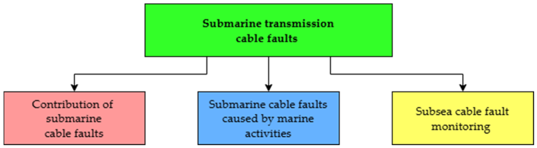
Previous studies have indicated that failures in STS have not been well documented, and little data has been accumulated due to the relatively short lifespan of offshore wind farms. Numerous studies for determining submarine cable faults can be found in the literature. This section first reviews the significance of submarine cable faults, their causes, and their contribution to overall failures in OWTFs. Thereafter, cable faults caused by human activities are reviewed, with subsea cable fault monitoring and position topologies discussed in the literature. Figure 2 provides submarine transmission cable faults for marine and subsea monitoring applications.

2.1. The Contribution of Submarine Cable Faults

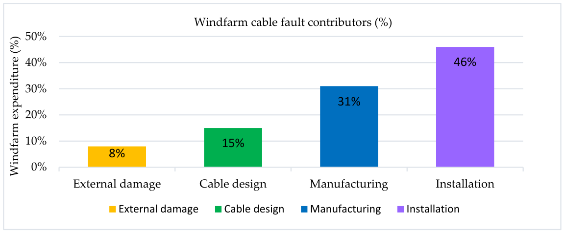
A technique employing three non-destructive examination methods, namely thermography, eddy current testing, and spread spectrum time-domain reflectometry (TDR), for the determination of the location of submarine cable faults, together with the identification of the causes of cable faults and the classification of their types, is discussed [8]. This study focuses on the structural capabilities of submarine cables. According to this study, subsea cable faults account for 80% of the total OWTF insurance expenditure, whereas the submarine cable infrastructure accounts for 9% of the overall OWTF spending. Subsea cable installation faults account for 46% of the overall expenditure, while cable manufacturing failures make up 31% of the total budget. Cable design flaws and external damage account for 15% and 8%, respectively. The results of this study show that there is currently no method to accurately determine the fault event, location, and type of physical failure in subsea cables under active loading.
The significance of submarine cable infrastructures related to design and failures, their impacts on dependability, as well as the consequential effects of the cable connection, operation, and shipping of submarine cables, is described [9]. An outcome of this study shows that offshore cable failures account for 80% of the financial expenses, even though the STS makes up less than 10% of the total OWTF costs.
The importance of accurate data, current submarine cable failures, the progression and development of submarine cable technologies, and the existing limited data on cable failures, with no effective concept to benchmark these failures, is further discussed [10]. Furthermore, various submarine cables are discussed for HVAC, MVAC, and HVDC cable systems, and the multiple technologies used for distances ranging from the onshore grid to the offshore collection point. Different failure modes for STS are also evaluated, with installation faults contributing 46%, cable manufacturing faults 31%, cable design faults 15%, and external damage 8% to STC faults as shown in Figure 3.

2.2. Submarine Cable Faults Caused by Marine Activities

A study completed by Chen et al. (2021) [11] develops an early warning system for submarine cable breakage caused by ship anchors. The sporadic effects of earthquakes, ocean currents, and ignorance of ship anchoring, along with the varying levels of faulting on submarine cables, require an early-detection procedure, as manual traversing is time-consuming and costly.
Another study focuses on a review of European offshore wind farm transmission failures and the inaccuracy in how these failures are documented [12]. Significant contributing factors to this problem include the relatively short lifespan of offshore wind farm transmission systems, transmission failures caused by trawling and ship anchors, and installation and commissioning issues. The system technology used, whether HVAC, MVAC, or HVDC, also plays a significant role in submarine transmission faults, as does the type of cable technology used, whether cross-linked polyethylene (XLPE), self-contained oil-filled (SCOF), or mineral-insulated. However, due to a lack of available failure data, as OWTFs are a relatively new technology, the findings of this study suggest that a more accurate failure analysis needs to be developed.
Research by Fotis et al. (2023) [7] describes the crucial issues in CIGRE recommendations and in IEC and IEEE standards for the installation and energization of a 150 kV submarine cable between the Greek islands and Europe, while incorporating fault detection methods throughout the undertaking. Human activities, particularly fishing and anchoring, are identified as the primary cause of cable failures, with shallow coasts most affected. The repair of these damaged cables may take days or months, depending on the severity of the fault. The result of this research is critical to cable manufacturing companies seeking to establish design parameters for subsea cables.
In research conducted by Wang et al. (2021) [13] the failures of HVAC and HVDC submarine cables are examined across various cable types and distances. Several submarine cable faults and their causes are reviewed, with short faults being the most frequent, caused by insulation failure. It was found that human interference accounts for a considerable amount of cable failures.
A further study focuses on the unbalanced charging current in the differential protection of high-voltage submarine cables and its consequences for a system’s differential protection relay. Outcomes of this research show that these factors must be considered during the development stage of the OWTF to ensure an effective protection scheme for the system [14].

2.3. Subsea Cable Fault Monitoring

A study by Bawart et al. (2014) [15] discusses how fault location for STC differs significantly from that of conventional fault cable position on submerged land cables. This study focuses on the various cable faults caused by human actions (such as ship anchors, fishing paraphernalia, and dredging) and environmental hazards (underwater earthquakes, underwater landslides, ocean floor erosion, turbidity tides, current tides, hurricanes, volcanic movement, fish and animal bites, and other natural risks). Various topologies used to determine cable fault location, including TDR, the Murray Bridge method, and other traditional techniques, are discussed. In this study, determining the exact location and distance of a fault from the onshore grid has its challenges.
Research by Dinmohammadi et al. (2019) [16] reports that high-tech monitoring technologies have been unable to detect 70% of the faults that have occurred in STCs over the past 15 years, with abrasion and corrosion accounting for 40% of these failures. A model using CableLife V1.0 (2019) software was developed to predict the submarine movement of the STCs, and it was determined that fault-location techniques such as TDR and Murray Bridge topologies are critical for determining subsea cable faults.
A study by Bawart et al. (2016) [17] introduces the use of a frequency-domain reflection (FDR) topology for determining the fault location on the most extensive 500 kV submarine cable in China. The FDR topology is a technique in which a high-frequency signal with a step amplitude is transmitted using FDR topology for determining the fault location on the reflected signal, at the same frequency but at different time intervals where the cable’s impedance mismatches. The reflected data is converted using the Inverse Fast Fourier Transform (FFT), and the fault distance can subsequently be calculated. The outcomes of this study indicate that FDR is more sensitive than TDR, and that FDR testing must be completed immediately after the submarine cable is installed. Various causes of STC faults and fault detection topologies, including TDR, fault burning, the multiple-impulse method, the impulse-current method (ICM), and the decay method, are discussed, with particular attention to TDR [17]. Two case studies of very long HVAC submarine cables are evaluated, comprising XLPE and mass-impregnated cables. The focus of this study is the reliability of the transmission system of an OWTF. The results indicate that, due to data unavailability and incorrect information, further investigation is needed.
Further investigations by O’Reilly et al. (2017) [18] investigated pinpointing the exact location of a submarine cable fault using a hydrophone string. This research examines the significant causes of faults arising from human activity and environmental factors, including high- and low-resistance faults, cable interruption faults, and sporadic faults. Fault detection methods for pre-location and pinpointing are discussed, with an emphasis on TDR and hydrophone methods, respectively. The results of this study indicate that this method requires further development for various submarine cables operating at extreme ocean depths. Table 1 presents research on the resolution of submarine cable faults for offshore wind farms.
In summary, 80% of faults that occur in OWTFs are caused by submarine cable faults, even though the STSs amount to only 10% of the total investment of an OWTF [8,9]. As submarine cables account for a large percentage of the faults encountered, it is necessary to review various topologies reported in the literature to identify practical solutions for locating the exact fault position and corresponding fault level.

3. Submarine Cable Fault Identification and Classification

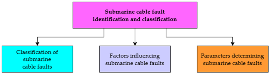
As previously discussed, there is little literature on techniques for identifying and accurately classifying submarine cable faults. This section reviews studies in the literature that classify cable faults into various categories as shown in Figure 4. Furthermore, these categories are explored in depth, with a focus on the topologies associated with each category and the mathematical formulations of the techniques discussed, thereby enabling effective detection of cable faults in submarine cables. Subsea cable faults focusing on their characteristics and the topologies used to determine the pre-location. Factors mitigating submarine cable faults are reviewed at the end of this section.

3.1. Classification of Submarine Cable Faults

A study by Gulski et al. (2021) [9] classifies submarine cable failures into five categories. These include manufacturing processes, submarine cable faults incurred during manufacturing, cable faults developed during the transportation of subsea cables, incorrect groundwork, operational forecasting, and environmental issues caused by dragging fish nets, anchoring, and cable scuffing from the cross movement of the submarine cable.
Another study also focuses on four main contributors to the failure of submarine cables for offshore wind farms in the United Kingdom. Incorrect cable design, defective manufacturing, improper installation of submarine cables, and external damage to submarine cables are factors contributing to cable faults [10].
Research completed by Bawart et al. (2014) [15] discusses the natural hazards that cause subsea cable faults, including natural disasters and oceanic events, and notes that human activities are the main contributors to cable faults. Furthermore, cable fault methods are classified into five categories, each with a corresponding fault-location topology for determining the exact fault location.
Most submarine cable faults are due to human error and occur during the pre-commissioning, commissioning, and post-commissioning stages [23]. Overextension of the subsea cable, anchorage damage, cable burial, cable transfer from the transport ship to the installation ship, and crisis cable clipping are factors that contribute to errors during pre-commissioning and commissioning. Natural disasters triggered by seismic events, cable fatigue in non-buried cable sections, and abrasion of subsea cables by ocean sediment and ocean currents can lead to post-commissioning cable faults. The most frequent causes of damage to subsea cables are anchorage damage, seabed scouring, angling activities such as trawling in shallow waters, shipwrecks, and other subsea projects [23].

3.2. Factors Influencing Submarine Cable Faults

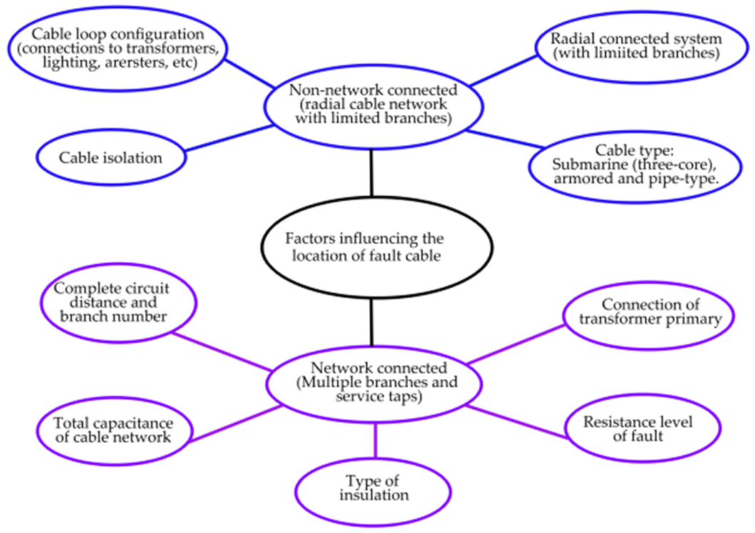
Factors to be considered in determining subsea cable faults also include whether the cable system is connected to the network. For an independent system not connected to the network, cable fault procedures can be easily developed and monitored. However, for a network-connected system, this becomes more complex because interrelated parameters must be considered [21]. Factors to consider for both systems are shown in Figure 5. Further considerations in classifying various fault types include the resistance values of the respective faults. For faults with a fault resistance of less than 100 ohms, TDR and bridge techniques are employed. For fault levels of above one hundred ohms but below ten mega-ohms, surge arc reflection, burn arc reflection, ICM, fault conditioning, together with TDR comparison, and bridge topologies are used. For fault resistance values above ten mega-ohms, surge or burn arc reflection, ICM (direct and differential), and the decay method (direct and differential) are utilized [21].

3.3. Parameters Determining Submarine Cable Faults

Submarine cable faults are characterized by typical positioning error parameters, including depth, geographic location, and environmental influences that can affect fault detection and assessment of accuracy. Research by Yu et al. (2025) [24] examines techniques for detecting and isolating faults in submarine cables utilized in seafloor observation networks. The authors developed a branch-unit system for disconnecting faulty cables and employed a fine-tuned CatBoost machine-learning model to classify fault types. They determined fault locations by analyzing current leakage at network nodes. The proposed method demonstrates high accuracy and a positioning error of within 5% in identifying and locating cable faults, essential for ensuring reliable long-term ocean monitoring.
Typical response time parameters for submarine cable faults include fault identification, location assessment, and mobilization of maintenance teams. It is crucial to minimize downtime and ensure rapid service restoration, typically aiming for response times within predefined limits based on fault severity and location. A study by Peng et al. (2026) [25] investigates the detection of high-impedance faults in three-core submarine cables, which are essential for power links from offshore wind farms. The authors propose a method that leverages modal voltage patterns to quickly and accurately identify faults, even with minimal fault currents. Their simulations demonstrate that this approach enhances the safety and reliability of underwater power transmission. Various fault-simulation results demonstrate that the proposed method completes all calculations in 0.06 s. The maximum fault distance estimation error is 0.608 km.
Another parameter to consider in submarine cable faults is noise tolerance, which is critical to ensure the reliable performance and integrity of underwater communication systems. These parameters define the acceptable noise levels that cables can withstand before signal degradation occurs, accounting for environmental conditions and system specifications. An investigation by Yu et al. (2023) [26] examines submarine optical cables used in underwater seismic monitoring, highlighting four types of fiber-optic seismic sensors, namely optical interferometers, fiber Bragg gratings, optical polarimeters, and distributed acoustic sensing. It emphasizes their ability to extend the seismic detection range while minimizing electromagnetic interference and corrosion. Additionally, the paper compares the advantages and disadvantages of each sensor type and discusses the technical requirements for improved submarine seismic monitoring. The above-mentioned methods have a noise floor of approximately 10 nε, a frequency response of 0.001 Hz to 100 Hz, and a sensing length restricted to under 100 km.
The detection rate for submarine cable faults varies significantly with fault resistance parameters. This analysis highlights the importance of understanding how these resistances affect fault detection capabilities. As previously mentioned in [17] (2016), fault types are classified into five categories: low-resistance faults (<100 Ω), high-resistance faults (in the kilo-ohm range), intermittent faults (activated above a certain voltage), interruptions (cable cuts), and sheath faults (damage to the cable jacket). This research highlights the use of DC sources for sheath insulation testing and of DC impulse signals for locating sheath faults, thereby facilitating early fault detection.
In summary, numerous techniques are employed in the literature to determine the pre-location of a submarine cable fault. Even though the percentage error is low when determining the fault position, the estimated fault location may still be off by a few kilometers. The pre-location method for determining the initial position of the faulted cable is a preliminary technique that precedes numerous pinpointing methodologies used to determine the exact fault location. Moreover, traditional techniques used to determine the diagnosis of a subsea cable fault tend to have a deficiency in the accurate determination of the fault [27]. Furthermore, typical parameters for a submarine cable undergoing a fault are discussed. Parameters include positioning error, response time, noise tolerance, and detection rate across various fault resistances, along with the applicable cable length.

4. Submarine Cable Fault Pre-Determination

Various techniques are employed to determine the fault location as shown in Figure 6, but these are limited by the extensive cable lengths. These techniques include insulation resistance measurements used to determine deteriorated insulation on a damaged cable core in three-core submarine cables [23] detect deteriorated insulation on the damaged core of Studies by [15,17] classify submarine cable faults into five categories: low-resistance, high-resistance, intermittent faults, interruption faults, and sheath faults.
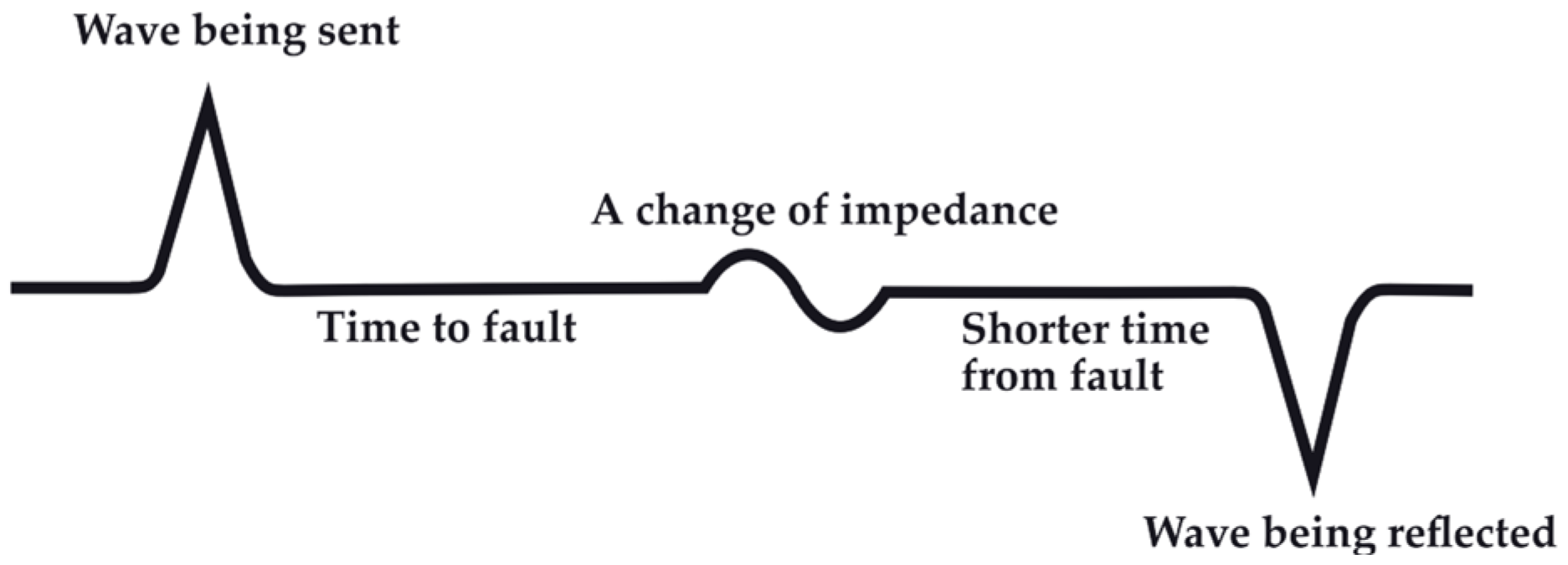
Low-resistance faults are found in cables with a resistance of less than 100 ohms and occur in short submarine cables [18]. Techniques employed to locate low-resistance core faults include TDR and the Murray loop bridge method [15,17]. The TDR technique is used to locate a break in the core of a faulty cable, and accurate results are obtained when this test is performed from both ends of the cable. A TDR device sends a low-voltage electrical waveform through one end of a submarine cable core, and if the cable is damaged, this reflected waveform is returned to the source at a lower amplitude. Depending on the magnitude of the fault, some of the energy is lost into the ocean. Figure 7 illustrates an example of a TDR reflected waveform [18,23].

4.1. Time Domain Reflectometry

Time Domain Reflectometry (TDR) is a diagnostic method used to detect and locate faults in submarine cables. The process consists of sending electrical pulses through the cable and analyzing the resulting reflections to identify any defects present. Submarine cable faults, including insulation breakdown, open circuits, and short circuits, result in observable signal changes, affecting voltage, current, time delay from reflections (TDR), and impedance.
Linear regression is a crucial method for establishing fault location using TDR. By applying linear regression, the relationship between reflected signals and fault positions can be modeled, enabling predictions of fault distances and attributes in submarine cables. This method enhances the accuracy and reliability of diagnostics in various fields, including telecommunications and electrical transmission systems. Linear regression in its simplest form is expressed in Equation (1) [28].
y i = f ( x i , θ ) + ε
where y i is considered as the output dependent variable (e.g., distance of the fault location), x i is the independent input variable (e.g., voltage or current level, time delay, impedance, etc.), θ is the unknown parameter and the measurement error ε is the difference between observed and predicted values.
The performance of prediction models is evaluated using the Root Mean Square Error (RMSE). This metric is determined by taking the square root of the average of the squared differences between predicted values and actual values, providing a measure of the model’s accuracy [29].
R M S E = i = 1 n ( x i x i ) 2 n
where x i are the predicted values, x i are the known values and n represents the number of observations. Linear regression has proven to be very effective for linear modelling with small datasets. For nonlinear modelling with complex datasets, a more effective solution for accurately determining cable faults would be the implementation of an artificial neural network [28,30].
Time-domain reflectometry and FDR are established with off-line fault-localization techniques used for various cable types. Despite their use, both methods exhibit notable accuracy limitations. Key performance factors include rise of time and frequency-sweep bandwidth, which influence effectiveness. Furthermore, both TDR and FDR are susceptible to noise interference. These limitations are particularly pronounced for submarine cables due to their extended lengths, which exacerbate the inherent challenges of accurate fault detection [31].
The TDR method is not successful for detecting a high resistance fault or intermittent fault, as the low voltage signal distributed by the TDR is not reflected at the point of failure, since the variance in fault impedance and healthy cable impedance does not significantly differ [32].
The optical TDR topology is used to locate a fault in a three-core cable and has the added benefit of a fiber-optic cable installed between the cores. Deploying the fiber-optic TDR method on both ends of the subsea cable determines the appropriate position of the cable fault, indicating a fractured or disrupted fiber-optic cable [20,33].
Fault burning is the process by which a high-resistance fault is converted into a low-resistance fault by a prevailing burner, typically a powerful DC supply with an elevated arcing potential and high current. Moreover, this will allow the TDR topology to find the location of the submarine cable fault [15,17].

4.2. Murray Loop Bridge

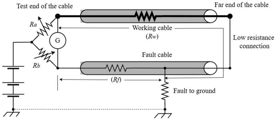
For low-resistance faults, the Murray loop bridge method, an advanced Wheatstone Bridge configuration, establishes symmetry between the resistances of two cores of equal length and is used when both cables are undamaged. Any imbalance between the resistances of the two cables will determine the exact position of the fault, as the fault position can be determined by the resistance per length of the respective cables [34]. The Murray loop bridge method is employed to find short circuit faults and earth faults on short subsea cables with a resistance of a hundred ohms or less [35].
For the Murray loop bridge topology in Figure 8, R f represents the resistance of the faulted cable. The working cable is represented by R w where R a and R b represents variable resistances which are used to balance the bridge combination. When the circuit is in a balanced mode, the faulted section’s resistance ( R f ) can be calculated using the following equations [36,37].
  R a R b = R w R f
R a + R b R b = R w + R f R f
R f = R b R a + R b   ( R w + R f )
As the cross-sectional area of the cable is identical and provided by the cable manufacturer, with the total lengths of the two installed subsea cables being predetermined, the distance of the cable fault ( D x ) can be determined with L representing the complete length of both the working and faulted cable [38,39].
D x = L R b R a + R b
High resistance faults occur in longer submarine cables with resistance in the kilo-ohm range [18]. Techniques employed in locating high resistance faults included the Varley loop bridge method, ICM, the multiple impulse method, the impulse current differential method, and fault burning [15].

4.3. Varley Loop

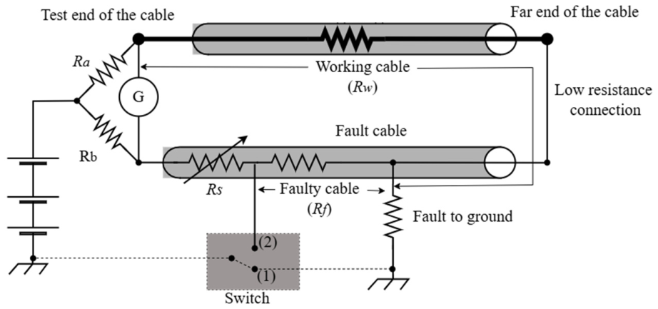
For high resistance faults over long cable lengths, the Varley loop method is employed [39] as shown in Figure 9. This method is like the Murray loop bridge method, as both are based on the Wheatstone bridge technique. The difference is that the Varley loop method does not contain the variable resistors R a and R b but comprises fixed resistors. Instead, a variable resistance ( R s ) is inserted in series with the faulted cable. This allows the Varley loop method to be less sensitive as opposed to the Murray Bridge loop method and can be incorporated in longer lengths of subsea cables [35]. The Varley loop method is employed to detect earth and short-circuit faults in long cables.
The first consideration is when the switch is connected to position 1. The variable resistor ( R s ) maintains the equilibrium state, and the faulted resistance value represented by R f is calculated in the equations that follow. The variable resistance is defined by R s 1 when connected to position 1 [39].
R a R b = R w R f + R s 1
R a + R b R b = R w + R f + R s 1 R f + R s 1
R f = R b ( R w + R f ) R a R s 1 R a + R b  
The second consideration is when the switch is in position 2. The variable resistor ( R s ) still maintains the equilibrium state and the variable resistance is defined by R s 2 when connected to position 2 [40].
R a R b = R w + R f   R s 2
R a R s 2 = R b ( R w + R f )  
Substituting (7) into (10), the fault resistance ( R f ) can be determined.
R f = R a ( R s 2 R s 1 ) R a + R b
As the resistance of the cable under fault can be determined, the distance of the cable fault ( D x ) can be determined with ( r ) representing the resistance per unit length of the cable.
D x = R f r

4.4. Impulse Current Method

The impulse current method (ICM) is another technique developed for detecting a high-resistance fault in a subsea cable [41]. A high voltage impulse operating in conjunction with a surge generator, better known as a thumper, is passed through the cable. At the point of a cable fault, a breakdown or flashover occurs, resulting in a short circuit. Current waveforms are generated that oscillate and return to the surge generator. The reflection of the current waveforms continues to happen until the waveform is extinguished [42]. The fault distance can be determined by the intervals of the current waveform, as continual traversing of the current waveform from the faulted point to the source of the cable occurs [32]. Using ICM, the distance ( D f ) to the faulted cable position can be determined by the insertion of the voltage waveform ( v f ) and the transmission period ( t f ), taking into consideration the time delay ( t 0 ) for the fault arc to develop [17].
D f = v f ( t f t 0 ) 2
Furthermore, the most developed method for high-resistance submarine cable fault pre-location is the secondary impulse method (SIM) or multiple impulse method (MIM) [32]. This technique involves injecting a low-voltage pulse into the submarine cable. When a fault occurs in the cable, the voltage pulse returns automatically, applying a high-voltage pulse to the fault location. The failure of the high-voltage pulse and the high-resistance fault generate a low-voltage pulse that returns to the fault position. This is identified and recorded by the secondary impulse measurement apparatus and further analyzed to determine the exact fault position [43].
Another technique for locating a high-resistance fault is the impulse current differential method (ICDM). This method is like the differential decay method, except it requires a second measurement at the coupled receiving end of the cables. This allows the currents to travel from the faulted cable to the reference cable via the coupler. The two waveforms are superimposed, and the fault point is determined. This allows for improved accuracy [15,17].
Intermittent faults occur when defects in the submarine cable’s insulation develop. These occur in the cable joints and connections. Topologies employed in the literature in determining the position of these cable faults include SIM, ICM, MIM, arc reflection, the decay method, and the differential decay method.

4.5. Decay Method

The decay method requires an HVDC supply to charge the submarine cable. In doing so, when the voltage exceeds the breakdown voltage at the point of fault, arcing occurs, and transient waveforms are detected by a capacitor-coupled device. These voltage oscillated waveforms are logged and investigated by TDR equipment [17].
The differential decay method uses two cables that operate differentially, each equipped with a coupler. The cables are energized using HVDC, and when a fault occurs, the pulse that is detected is registered by the TDR device [15,17]. The ICM is dependent on the non-stop monitoring of the voltage waveforms, whereby the exact position of the fault is determined by the time transpired ( t x ) of the initial pulse to the arrival of the waveform of the same divergence to the TDR. However, the period of one successful waveform sequence lasts four times longer than the distance traveled by the waveform. The distance ( D x ) of the fault is determined as follows, where ( v f ) is the voltage waveform [17].
D x = v f t x 4

4.6. Remotely Operated Vehicles

A more tedious cable fault-location method is to employ a remotely operated vehicle to traverse the length of the subsea cable. Numerous images are captured of the subsea cable and visually checked [44]. Furthermore, remotely operated vehicles are also equipped with search coils. The faulty cable is injected with a tone current, and at the point of fault, there will be a change in the magnetic field of the damaged subsea cable [23].
Table 2 summarizes various subsea cable faults, focusing on their characteristics and the topologies used to determine the fault’s pre-location.
In summary, faults that occur in subsea power cables include low-resistance faults (typically less than 100 ohms), high-resistance faults (in the kilo-ohm range), intermittent faults, interruption faults, and sheath faults. From the IEEE 1234-2019 standards (2019) [21]: low-resistance faults are presented as short-circuit faults; high-resistance faults are described as nonlinear (voltage- or current-dependent) faults; and intermittent faults, together with interruption and sheath faults, are classified as flashing, intermittent, or open-circuit faults. Furthermore, the most common topology used in pre-locating faults is TDR, used to determine the location of short-circuit faults, bolted faults, open conductors, metallic shield, or sheath corrosion. Moreover, surge-arc reflection and ICM are incorporated to determine the pre-location of high-resistance, water-soaked, and HV flashover faults.

5. Pinpointing of Submarine Cable Faults

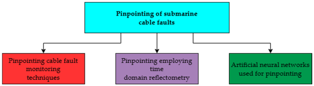
Submarine cable fault pinpointing is a critical aspect of maintaining the reliability of underwater communication and power systems as shown in Figure 10. Various innovative methods have been developed to enhance the accuracy and efficiency of locating faults in submarine cables. These methods leverage advanced technologies such as hydrophones, (time or frequency) domain reflectometry, and artificial neural networks, each contributing unique advantages to fault detection.

5.1. Pinpointing Cable Fault Monitoring Techniques

The study by Joo et al. (2024) [45] discusses the functionality and preservation of HVDC mass-impregnated (MI) subsea cables between the Korean mainland and the island of Jeju. Various aspects, such as current protection of the subsea cable, instantaneous fault detection topologies, operational dependability, and continuous monitoring systems, are examined through various monitoring techniques. These techniques include diving check-ups, remotely controlled vehicles, ship surveillance, TDR, and distributed acoustic sensing (DAS). In a study by [22], the FDR topology is employed to locate a fault in a subsea cable in China’s most extensive 500 kV submarine cable system. The outcomes of this study show that FDR is more susceptible than TDR, and that TDR evaluation is critical during pre-installation.
A study by [18] sought to locate a subsea cable fault using a hydrophone string. Numerous fault factors, including high- and low-resistance faults, cable disruptions, and intermittent faults, were reviewed. Fault recognition using TDR and hydrophone topologies was the focus of this study to predetermine the presence of a cable fault.

5.2. Pinpointing Employing Time Domain Reflectometry

Research summary provided in Table 3 presents the required testing of a 150 kV submarine cable in the Aegean Sea located between Europe and the Greek islands [7], with the IEC TB 733 standards [20] and IEEE 1234-2019 standards [21] as its lawful ethics. Numerous fault location methods are reviewed, which include TDR, bridge measurements (Murray loop bridge), and optical TDR topologies. The TDR technique identifies impedance differences along the cable by injecting a signal into the conductor and measuring the time for the reflected signal to return from the point of disturbance to the source. With the time measured and the signal propagation velocity determined, the exact position of the fault can be calculated. Research completed by Bawart, et al. (2016) [17] extensively examines fault detection methods, namely TDR, fault burning, multiple-impulse method, ICM, and decay method, with a focus on TDR. In another study by Bawart, et al. (2014) [15], various techniques, including TDR, the Murray Bridge method, and other conventional methods, are reviewed.
For the exact position and type of subsea cable faults, together with their respective classification, Nicholls-Lee, et al. (2022) [8] examines three non-destructive techniques: thermography, eddy current assessment, and spread-spectrum TDR. This study focuses on the structural capabilities of submarine cables.
Further discussions by Lee et al. (2020) [46] employ time-frequency domain reflectometry (TFDR) in real-time industry applications, and the testing of this application on the HVDC cable between Jeju Island and the Korean mainland. Both studies revealed an ongoing need to further develop fault-tolerant, innovative recognition systems and high-tech monitoring topologies, such as employing NNs, to overcome one of the limitations of TFDR.

5.3. Artificial Neural Networks Used for Pinpointing

Research by Ashrafi Niaki et al. (2023) [47] developed a method for the precise location of a sub-ocean cable fault for HVDC faults using voltage signals of the cable casing using a developed artificial neural network (ANN). This research demonstrated that the exact locations of DC faults were identified using an ANN algorithm. Various fault conditions, positions, and fault resistances were effectively studied. The results obtained from this study were within 1% of the error in determining the respective fault location.
In summary, traditional fault detection and location methods, including TDR and cable fault detection via impedance analysis, are limited by harsh environmental conditions, long cable lengths, and weak fault indications. These techniques to detect STC faults have been further enhanced through the development of deep learning and artificial intelligence.

6. Neural Networks Application to Submarine Cable Fault Identification

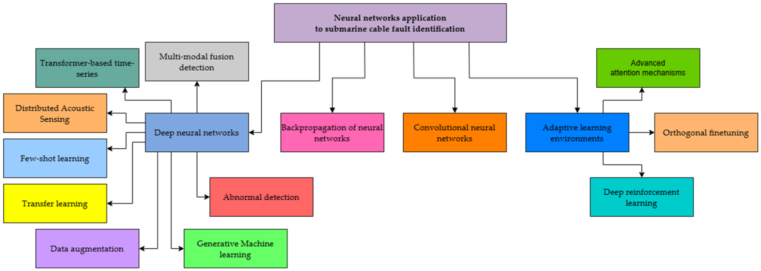
In this section, various deep learning strategies for NN applications as shown in Figure 11 related to submarine cable faults will be discussed and summarized. The literature discussed focuses on state-of-the-art applications of NNs for STC fault detection, covering various architectural types, detected fault types, performance strategies, and practical solutions.
Various NN architectures have been proposed in the literature for subsea cable fault detection and localization. Architectures utilizing deep learning, where large datasets are critical in their solution strategies, include multi-modal fusion detection and transformer-based time-series topology. Distributed Acoustic Sensing (DAS), together with artificial intelligence, enables techniques for determining conditions around the submarine cable that can effectively cause damage to the subsea cable. Architectures incorporating deep learning, where significantly smaller datasets are beneficial in efficient solutions, include few-shot learning, transfer learning, and data augmentation, which are discussed as specialized and advanced areas within deep learning. A review of backpropagation NNs and convolutional NNs is also mentioned. These architectures are used to detect high-impedance, open-circuit, and ground faults, as well as mechanical damage to the STC.

6.1. Deep Neural Networks

Deep neural networks are increasingly used to detect and predict faults in submarine cables. Utilizing advanced algorithms, these networks analyze large datasets to identify patterns indicative of potential failures. This technological innovation greatly improves the monitoring and maintenance of submarine cables, potentially reducing downtime and enhancing the reliability of underwater communication systems.
Research presented by Liu et al. (2024) [48] developed an innovative approach to detecting submarine cables using magnetic data processed through deep learning techniques. It eliminates the need for complex manual operations such as field separation and denoising. The method employs an end-to-end NN that directly correlates magnetic data with cable positions. The findings indicated that this approach achieved greater accuracy than traditional Euler methods and effectively reduced false positives by employing clustering techniques.
An investigation by Sun et al. (2025) [49] discusses the challenge of early fault detection in long DC submarine cables used in offshore wind systems, emphasizing the difficulty in recognizing initial fault signs that may lead to serious problems if not promptly addressed. The authors introduce an innovative approach that combines electrical signals and temperature data using an enhanced Bagging ensemble learning model, achieving a remarkable accuracy of around 98.9% for early fault detection.
A study by Shao et al. (2025) [50] reviews the causes of faults in transmission cables and the traditional techniques reported in the literature for fault detection and location. Moreover, this research examines the application of artificial intelligence to the detection and localization of transmission cable faults, with a focus on deep NNs. Research trends and drawbacks are further investigated and assessed. Sectional cable overheating, moisture ingress, and mechanical damage are the three main contributors to cable faults, leading to insulation degradation. Traditional fault detection methods include traveling-wave propagation theory and equivalent cable parameter modeling, in which fault currents, voltages, and impedance ranges are modeled and analyzed.

6.1.1. Multi-Modal Fusion Detection

Multi-modal fusion detection utilizing artificial intelligence significantly improves fault identification and diagnosis in submarine cables. This technique merges multiple sensing modalities, including acoustic, electrical, and optical data, to enhance detection accuracy and reliability. By applying artificial intelligence algorithms, the system efficiently analyzes complex datasets, enabling quicker response times and reducing potential downtime. The artificial intelligence component introduces adaptive learning, enabling the system to improve its performance using historical data, ultimately fostering more effective maintenance strategies and greater operational reliability for submarine cable infrastructure.
Work completed by Wang et al. (2023) [51] investigated a multi-model fusion approach that integrated statistical learning and deep learning techniques to enhance the identification of abnormal vibrations in underground cables. It addressed the challenges of rapidly localizing faults in cables buried in urban settings, aiming to increase both the speed and accuracy of fault detection. The research employed distributed fiber-optic sensing to capture vibration and spatiotemporal features along the cables, thereby providing early warnings and precise positioning of potential damage.
A study by Cui et al. (2024) [52] investigated the safeguarding of submarine cables by employing a multi-modal fusion algorithm that combined Automatic Identification System data, radar information, and fishery safety details to mitigate risks associated with ship anchors. These subsea cables, vital for energy and communication, require robust risk assessment strategies. The methodology included monitoring ship movements using shore-based radar and Automatic Identification System data to compute risk levels concerning the cables. The principal aim was to minimize cable damage by enhancing risk identification and assessment related to vessel activities.
Further research by Kumar et al. (2025) [53] discusses the transformative application of artificial intelligence in the management of underground transmission cables within smart cities. It integrates multimodal sensor networks, advanced machine learning models such as convolutional NNs, Random Forest, and Long Short-Term Memory (LSTM) networks, and a digital twin to facilitate real-time monitoring. The system was evaluated over a 250 km area in a Southeast Asian city, achieving an impressive fault-detection accuracy of 94%. Notable outcomes included a 40% reduction in repair times and a 37% decrease in maintenance costs.

6.1.2. Transformer-Based Time-Series

Transformer-based time-series methods for submarine cable fault detection leverage the strengths of transformer neural networks to analyze sensor data from underwater cable systems, thereby identifying anomalies and potential failures. The transformer architecture’s ability to model long-range dependencies in time-series data enables it to effectively recognize complex fault patterns. By implementing these methods, the reliability and efficiency of submarine cable monitoring can be enhanced, resulting in faster fault detection and minimized downtime during repair activities.
Transformer models are effective in fault diagnosis via sequential and time-series data processing. Yet, they require significant labeled data, which is expensive to acquire. To mitigate this issue, a new active learning approach was proposed, specifically for transformer-based fault diagnosis. A study by Johari et al. (2025) [54] focused on fault diagnosis in 5G and future mobile networks, leveraging transformer models, which excel at analyzing time-series data but typically require many labeled fault examples. To mitigate the labeling challenge, the authors proposed an active learning approach that prioritized selecting the most informative samples for expert labeling. By harnessing transformers’ attention mechanism, the method effectively identified unusual patterns, thereby concentrating data curation efforts on the most crucial areas. The study significantly improved the accuracy of fault diagnosis in network management and effectively identified samples from previously unseen fault types, thereby tackling critical issues in this domain. It not only improved the precision in identifying known issues but also effectively detected samples related to previously unseen fault types. This capability addressed several critical challenges prevalent in network management. Experimental findings indicated that this approach surpassed traditional techniques while requiring only 50% of the labeled data.
Research by Zhou (2025) [55] aimed to create an advanced disaster early warning and emergency response system tailored for underground cables by leveraging digital twin technology. It synthesized cable sensor data, GIS data, geographic information, and historical maintenance records into a comprehensive digital twin model, thereby improving the accuracy of data modeling. The study incorporated a transformer-based method for time-series prediction to enhance fault detection and applied reinforcement learning techniques to reduce false alarms and unexploited discoveries while improving response strategies.
Further investigations by Duthé et al. (2024) [56] employed a novel unsupervised machine learning methodology for monitoring OWF cable protection systems, using contrasting learning and Distributed Acoustic Sensing (DAS) data. A transformer NN was adapted for time-series data from high-frequency, noisy DAS cable protection systems (CPS) and trained to learn an intelligible representation of the information using a contrastive learning structure that imposed progressive evenness in the dormant arena. This was used to detect anomalies unsupervised, reducing the cost of capturing traditional OFWF CPS data. Through the deep learning of the data, artificial anomalies could be detected. However, it was noted that the system’s robustness required improvement to ensure effective deployment in an industrial environment. Moreover, environmental influences such as tides, wind speed, and wave height should be considered to improve anomaly detection further. Fault location topologies reviewed include traveling-wave methods and signal processing techniques, such as various wavelet transform topologies, including the continuous wavelet transform, the empirical wavelet transform, the FFT, the numerical Laplace transform, and the time-domain transform. These techniques are, however, limited by the challenges posed by the progressive growth of a power system network. These challenges include variations in fault detection due to inaccurate modeling; the ineffectiveness of large-scale data volumes, which results in poor computational efficiency of traditional methods and prolonged fault-location periods; and limited adaptability to distributed power integration and grid growth. Moreover, ANNs, including traditional machine learning, supervised support vector machines, and adaptive neuro-fuzzy interference systems (NNs with the philosophical advantages of fuzzy logic), are extensively reviewed for cable fault detection. Furthermore, ANNs, support vector machines, and genetic algorithm topologies are discussed for determining the location of a cable fault. This paper further reviews the application of artificial intelligence in detecting and locating cable faults. These techniques include deep belief networks, the attention mechanism, convolutional NNs, and, in the latter category, LSTM networks and graph convolutional networks. The advantages and limitations of artificial intelligence topologies are extensively reviewed.

6.1.3. Distributed Acoustic Sensing

Distributed Acoustic Sensing (DAS) combined with deep learning offers a cutting-edge, real-time monitoring solution for identifying submarine transmission cable faults. This technology transforms fiber-optic communication cables into numerous distributed vibration sensors, enabling the detection, localization, and classification of threats or faults in subsea power cables. By examining the acoustic and vibrational signatures generated by external disturbances, such as anchor drops, or internal failures, such as partial discharge, DAS delivers proactive, high-resolution surveillance of underwater infrastructure.
Work presented by Shao et al. (2025) [57] explored the integration of artificial intelligence with DAS technology, focusing on its applications within engineering. It highlights the capability of real-time acoustic signal detection using fiber optics, enhanced by artificial intelligence, which improves data handling, event recognition, and overall system intelligence. The technology demonstrates broad applicability across sectors such as transportation, energy, and security.
An investigation by Soto et al. (2024) [58] investigated the potential of submarine optical fiber cables to function as extensive networks of vibration sensors through the application of DAS. It demonstrated how this technology can be utilized to monitor geological phenomena such as earthquakes, as well as oceanic waves and currents, leveraging deep learning techniques to enhance quake detection accuracy. The analysis employs a commercially available DAS system installed on a cable located off the coast of Valparaíso, Chile. Findings indicate that these underwater cables can effectively serve as seismic sensors, presenting an economical solution for monitoring remote regions that are typically challenging to assess with conventional equipment.
A study by Davis et al. (2026) [59] examined advanced NN models designed to predict ocean surface waves by analyzing strain data obtained from submarine fiber-optic cables through DAS. These models, developed using data collected near Alaska, demonstrate superior performance to conventional methods for estimating wave height and period. A key advantage is their capability to measure waves across multiple locations along a cable, rather than being limited to a single point.
Collecting sufficient labeled data is difficult, time-consuming, expensive, and complex. Overfitting in submarine cable fault analysis also occurs when predictive models learn from noise in the training data rather than the underlying distribution, leading to poor performance on new data. To mitigate overfitting, techniques such as regularization, cross-validation, and simpler models can be employed to enhance prediction accuracy and reliability. In instances where the dataset is scarce, specialized deep learning topologies such as few-shot learning, transfer learning, data augmentation, and generative machine learning topologies are particularly promising, yielding high-quality results. These topologies can be effectively employed in practical applications, as the need for large datasets is drastically reduced.

6.1.4. Few-Shot Learning

When training examples or data are limited, unavailable, expensive, or time-consuming to obtain, few-shot learning (FSL) is an efficient machine learning approach. This topology replicates human learning by leveraging prior knowledge to grasp new concepts with minimal data, unlike traditional supervised learning, which relies on large datasets for effective simplification.
Research by Jin et al. (2023) [60] conducted a study that addressed fault diagnosis for offshore wind turbines, particularly with limited data and varying fault severity. An ordinal classification prototypical networks model that integrates FSL with ordinal regression for effective fault identification was presented. Realistic results demonstrate that this model outperformed existing methods and assisted expert partialities regarding fault importance.
In another study, Zhang et al. (2025) [61] presented a FSL approach utilizing a Siamese neural network for determining faults in buried HVDC transmission cables inside tunnels. This research tackled the issue of limited fault data and complex fault scenarios, outperforming classical convolutional NNs and deep belief networks. Moreover, the model demonstrated an accuracy above 90%, with a sustained accuracy of 93% in scenarios involving multiple coupled faults. Minimal data requirements and simulation of six various fault types were key features of this research.
Further research by Zhang et al. (2023) [62] proposed a method of determining small defects in transmission lines with limited samples by applying a few-shot detection algorithm. The research presented the Attention-Meta region-based convolutional NN, a meta-learning model that improved feature extraction and fusion through a Feature Enhancement Pyramid Network and Multi-spectral Feature Coding. A significant increase in the accuracy of detecting small defects in a transmission line was demonstrated through testing on a custom dataset.

6.1.5. Transfer Learning

Transfer learning is another technique employed in the literature when data are scarce. Transfer learning enhances the accuracy and efficiency of fault detection in transmission cables by leveraging pre-trained models from related domains. There is a reduction in reliance on extensive labeled training data, enabling faster, more effective fault identification and, overall, improving OWTF maintenance and operational activities.
An investigation by Paldino et al. (2024) [63] explores enhancing the thermal dynamic rating of transmission lines through transfer learning. This reduces the number of sensors required while retaining reliable temperature estimates. The thermal dynamic rating adjusts line capacity based on weather conditions, providing better control of renewable energy variations than thermal static ratings. Real-time tests conducted on transmission lines demonstrated that transfer learning significantly improves the accuracy and reliability of conductor temperature determination, thereby making dynamic thermal rating more feasible and cost-effective while reducing the number of required data points.
A study by Swaminathan et al. (2021) [64] introduces a convolutional NN and long-short-term memory network model to classify and locate faults in underground power cables by analyzing current and voltage waveforms. The model uses a sliding window with modeled noise to improve performance across varied environments. The method is also compared with existing approaches and explores the potential for transfer learning in comparable approaches, using a significantly smaller dataset. The results from this research indicate that the time required to train the network and the amount of data needed are considerably reduced, enabling practical applications.
Research conducted by Zou et al. (2023) [65] discusses a data-driven method for transmission line fault location incorporating transfer learning. The study addresses the constraints of traditional topologies that require exact line parameters or high sampling rates. The proposed solution involves training an NN on simulated data, then fine-tuning it on a limited dataset that reflects real-world system variations. The result is an increase in fault-location accuracy without requiring extensive real-world fault data. Further investigations include data augmentation, which may improve the algorithm’s performance.

6.1.6. Data Augmentation

Data augmentation methods typically improve the analysis and performance of submarine cable systems by improving the accuracy and robustness of design and operational models. By generating synthetic data or augmenting existing datasets with scarce information, these methods better characterize environmental and operational conditions, thereby improving predictive modeling for maintenance and failure prevention.
An investigation by Song et al. (2020) [66] examines the influence of data augmentation techniques on target recognition accuracy during unmanned aerial vehicle-based transmission line inspections, specifically for recognizing insulator strings. It evaluates methods such as histogram equalization, Gaussian blur, random translation, scaling, cutout, and rotation. The findings indicate that including augmented samples in training and test sets significantly enhances model performance, with Gaussian blur, scaling, and rotation particularly effective in improving recognition.
A study performed by Raymond et al. (2022) [67] addresses the diagnosis of insulation faults using partial discharge data, highlighting the impact of real-world noise. The study presents a novel data augmentation technique that incorporates simulated noise into clean partial discharge data to enhance the training of convolutional NNs. This approach improves fault classification accuracy by nearly 30% under noisy conditions, while maintaining consistent performance in cleaner environments.
Research by Thum et al. (2020) [68] focused on improving the way underwater cables are classified using images, through the application of various deep convolutional NNs, where transfer learning and data augmentation were applied to improve the classification accuracy. Typical methods that use handcrafted features did not handle underwater conditions well, whereas deep learning models captured more complex features. Among the several models demonstrated, MobileNetV2 achieved superior performance, with the highest accuracy of 93.5% and faster computation, making it optimal for underwater cable image classification tasks.

6.1.7. Generative Machine Learning

Generative machine learning models, notably Generative Adversarial Networks (GANs) and Variational Autoencoders (VAEs), are gaining traction in submarine cable fault detection. These advanced models address the challenge posed by limited real-world fault data by simulating complex, non-stationary signals. This includes interference from sources such as ships, anchors, and fishing activities, which enables the development of highly accurate diagnostic systems.
A study by Chu et al. (2024) [69] addresses the diagnosis of faults in underwater thrusters, crucial for the functionality of underwater vehicles. It proposes a novel approach that merges the generation of training data via GANs with a refined fault classification technique utilizing an enhanced temporal convolutional network. This combination effectively identifies complex faults, such as propeller entanglement and transmission issues, particularly where available real data is limited. Experiments demonstrate that the proposed approach is highly effective on both the EMU-Dataset and SIM-Dataset. The average F1 scores achieved are 0.9817 for the EMU-Dataset and 0.9962 for the SIM-Dataset. Additionally, overall performance improves by approximately 6.095% for the EMU-Dataset and 11.084% for the SIM-Dataset. The findings indicate a significant improvement in diagnostic accuracy over previous methodologies, thereby increasing the safety of underwater vehicle operations.
Research by Yao et al. (2024) [70] presents a groundbreaking technique aimed at enhancing the clarity of underwater cable images by integrating a convolutional NN and a GAN. It addresses common issues such as noise and interference in images taken by remotely operated vehicles. The findings signify its effectiveness, evidenced by improved clarity and precision. In severely polluted water conditions, images exhibit a Peak Signal-to-Noise Ratio of 28.67 dB and a Structural Similarity Index of 0.8965. However, in scenarios with uneven lighting, the Peak Signal-to-Noise Ratio decreases to 24.37 dB, accompanied by a Structural Similarity Index of 0.88. These improvements in image quality are crucial for enhancing underwater image filtering, which is essential for stabilizing the power system. This advancement ultimately facilitates more effective monitoring and maintenance of underwater power cables.
Further investigation by Chatterjee et al. (2025) [71] addresses the challenge of detecting faults in wind turbines, emphasizing the scarcity and uneven distribution of fault data across different types. To overcome this issue, the authors employ a Wasserstein Conditional GAN to generate synthetic fault data, successfully balancing the data classes and enhancing fault classification accuracy. Their method was tested on SCADA data from wind turbines, demonstrating superior performance compared to other approaches, largely due to the high-quality and stable nature of the samples generated during training. On average, the proposed GAN model establishes a classification correctness of approximately 69%.
A study performed by Khan et al. (2023) [72] introduces an innovative method for classifying and locating faults in power transmission networks by employing VAEs to generate synthetic data, enhancing the training of machine learning models. The study evaluates various algorithms, including Cat-Boost, Support Vector Machines, Decision Trees, Random Forest, and K-Nearest Neighbors. The results are notable, achieving almost 99% accuracy in fault identification and highly accurate localization with minimal error.
Research conducted by Mentzelopoulos et al. (2024) [73] investigates the application of variational autoencoders (VAEs) to generate synthetic data that emulates real vortex-induced vibrations (VIV). It further examines training transformers on this synthetic data to predict complex, nonstationary vibrations in both space and time using limited sensor information. The study evaluates the transformer model’s predictive accuracy against experimental data and compares its forecasting capabilities with those of LSTM and other deep neural networks. The primary objective is to determine whether VAEs can generate physically meaningful data for model training, thereby enhancing vibration forecasting for flexible structures subjected to fluid forces.
In another study, Sundsgaard et al. (2025) [74] explore the application of VAEs in enhancing data quality for distribution grid cable networks, with a specific focus on medium-voltage cables in Denmark. It addresses issues related to missing installation age data and imbalances in failure records. VAEs are employed for synthetic data generation, data imputation, and detecting outliers. The study also discusses existing challenges and proposes directions for future research, including adopting more advanced learning techniques and extending coverage to a broader grid.

6.1.8. Abnormal Detection of Artificial Neural Networks

Graph Neural Networks (GNNs) are advanced deep learning architectures specifically formulated to analyze graph-structured data comprising nodes and edges. They are particularly effective in understanding the relationships and dependencies within this type of data. A crucial feature of these networks is the “message passing” mechanism, which assists the aggregation of information from adjacent nodes, thereby supporting key tasks such as node classification, link prediction, and comprehensive graph analysis.
A study by Khemani et al. (2024) [75] examines the integration of deep learning with graph data, focusing on identifying nodes and edges in text and entities to construct graph structures. It highlights the significance of various GNN models, including graph convolution networks, GraphSAGE, and graph attention networks, in facilitating effective information exchange. The analysis delves into the message-passing mechanisms inherent to GNNs, evaluating their strengths, limitations, and diverse applications. Additionally, it discusses the relevant datasets and Python V3.1x (2023) libraries that support this area of research.
There has been an increase in studies focusing on extending deep learning techniques to graph data. Research by Wu et al. (2020) [76] provides an in-depth overview of GNNs in data mining and machine learning, introducing a new taxonomy that classifies state-of-the-art GNNs into four distinct categories: recurrent GNNs, convolutional GNNs, graph autoencoders, and spatial–temporal GNNs. It also discusses the varied applications of GNNs across domains and summarizes available open-source code, benchmark datasets, and model evaluations. Furthermore, the article highlights potential research directions in this dynamically evolving field.
Research by Lin et al. (2025) [77] investigates damage detection in the outer layers of power cables, which can arise from mechanical wear, moisture, or chemical exposure. The authors developed a physical model to study how these defects affect the cables’ electrical signals and collected leakage current data from compromised cables. Utilizing advanced signal processing techniques, they analyzed various frequency components. By integrating graph neural networks with LSTM networks, they were able to determine the type and severity of sheath damage. This novel approach has the potential to enhance the monitoring and maintenance of cable health.
Another innovative topology for abnormal detection is the data-driven, quad-level deep learning approach, which provides a robust and accurate method for the real-time detection, classification, and localization of faults in underground power cables. This methodology comprises four essential steps, namely data collection, feature extraction and reduction, fault detection, and classification/location. By leveraging artificial intelligence, this approach effectively overcomes the constraints of traditional, model-based techniques.
In another study, Shivaie et al. (2020) [78] introduce a framework to improve the resilience of power grids against earthquakes and terrorist attacks through an integrated approach that enhances generation and transmission capacities. The framework features a quad-level optimization model in which the first level outlines immediate corrective actions post-incident, such as adjustments to generation and grid configurations, and the second level simulates scenarios to assess the impacts of seismic and terrorist events. The third and fourth levels focus on long-term development strategies to increase generation and transmission capabilities, including the installation of devices to switch transmission lines. A unique algorithm inspired by the operational dynamics of symphony orchestras is utilized to address these issues. The model was validated on a 400-kV grid in Iran, demonstrating significant potential to improve overall grid resilience.
Research completed by Liang et al. (2025) [79] explores the management of large-scale renewable energy sources in hybrid AC/DC microgrids using a novel four-level energy management framework. This framework employs a data-driven model that adapts its conservativeness based on the variable output of renewable energy sources. By utilizing graph neural networks, it effectively identifies and eliminates unreliable data, enhancing the microgrid’s stability and reliability. Furthermore, the study introduces a new testing method called quasi-TOAT, which aims to bolster both efficiency and robustness amidst supply fluctuations. Comparative analyses in real hybrid AC/DC microgrid environments demonstrate that this innovative approach significantly outperforms traditional methods, particularly in handling uncertainties associated with renewable energy sources, highlighting its potential for widespread application in energy management systems.

6.2. Backpropagation of Neural Networks

Research concluded by Wang et al. (2024) [80] developed a backpropagation NN model to accurately determine the impedance characteristics of coaxial cable without specialized equipment. Not only were the load characteristics detected, but the model also identified potential open- and short-circuit cable faults, as well as dampness-related cable faults. The backpropagation NN was developed in MATLAB 2023b for ease of visualization, robustness, and a user-friendly interface. The NN was developed with nine input neurons, a ten-neuron hidden layer, and one output neuron. The sigmoid activation function was used for the hidden layer, facilitating the solution of non-linear problems and thereby increasing learning capability. The linear activation function was assigned to the output neuron to support regression. Furthermore, the Adam optimizer was used to optimize the network. The test cable’s impedance changed when a cable fault occurred, altering the load characteristics under normal operating conditions. The NN model’s measurement results were compared with those obtained from a GWINSTEK LCR-819 tester and were found to be only marginally consistent. Precise detection and fault identification of cable characteristics were achieved using a backpropagation NN and analysis of cable impedance data.
Research completed by Li et al. (2024) [81] develops a method of determining the cable sheath damage of a simulated 220 kV HV AC cable using COMSOL Multiphysics V6.1. The backpropagation NN topology was used to establish an efficient technique for determining the state of the sheath of the damaged cable by means of temperature data received on the surface of the cable sheath. The simulated network was developed using Python 36 in conjunction with the TensorFlow open-source framework, and the normalization method was utilized. From the study, it was determined that the accuracy of detecting damage to the outer sheath equated to 94.29%.

6.3. Convolutional Neural Networks

A study by Xiao et al. (2020) [82] presents a deep learning topology for training and detecting a submarine cable fault. Various algorithms that use current and voltage node data, admittance matrices that exclude Zener diode components from the model, and models that include Zener diodes, all employing Kirchhoff’s laws of voltage and current, are discussed for STC fault location in subsea observation networks. Furthermore, the application of deep learning in NNs for determining fault identification in machinery and electromechanical systems is discussed. To determine bearing fault detection accuracy and robustness, a convolutional NN is employed. This research incorporates the first and second layers of subsea branch units and secondary junction boxes for fault diagnosis of high-impedance, open-circuit, and short-circuit faults. These faults are detected using voltage and current data from the nodes of the junction boxes via real-time data transfer. PSpice is used to simulate the submarine observation network model and the deep learning model trained for single- and dual-shore-station systems. This deep NN application proved effective in locating and predicting the faults. Moreover, the chosen topology significantly improves the reliability of subsea observation network methods.
Further research by Zhang (2023) [83] determines early detection of submarine cable faults caused by the influence of overcurrent’s, using the convolutional NN. A model is developed in PSCAD/EMTDC to simulate a 25 kV cable fault and generate datasets. The wavelet transform is used to extract thirty typical constraints of the overcurrent samples in the time and frequency domains. The study utilizes an adaptive learning rate, in which changes in the function measuring the difference between predicted and actual values are considered and affect the model’s learning process. This minimizes errors during the learning process. Furthermore, regularization enhances the model’s ability to perform effectively on data not seen beyond the training datasets. This further enhances the model’s practical reliability and pertinence. By utilizing the wavelet transform and the convolutional NN, this method improved the accuracy and reliability of cable fault identification and classification. Table 4 provides the review summary on cable fault analysis using NNs.
In summary, NNs, with their ability to learn complex models from high-dimensional data, offer more viable solutions for identifying small fault-level discrepancies compared to traditional methods.

6.4. Adaptive Learning Environments

Adaptive learning environments are being utilized to address faults in submarine cables. These environments leverage advanced algorithms and machine learning techniques to identify, analyze, and predict potential failures in submarine cable systems. The application of adaptive learning not only enhances fault detection but also improves maintenance schedules and reduces downtime. By continuously learning from past data and incidents, the system becomes more efficient over time, adapting to the unique characteristics of different cable layouts and environmental factors. This innovative approach aims to improve the reliability and longevity of submarine cable infrastructure, ultimately contributing to more resilient global communication networks.

6.4.1. Advanced Attention Mechanisms

Advanced attention mechanisms play a crucial role in enhancing fault detection and identification within submarine cables. Recent research indicates that integrating self-attention with other attention-based models within deep learning frameworks significantly improves the accuracy and robustness of fault diagnosis in fiber-optic composite submarine cables.
A study by Peng et al. (2025) [84] investigates smart technology designed to detect hidden grounding issues in optical cables used in substations, with a specific focus on optical Ground Wire cables. It employs an attention model to assess transient electric fields and uses the wavelet packet transform to extract signal energy features. The methodology incorporates spatial and channel attention mechanisms, enabling visualization of fault points in 2D and 3D. The resulting system demonstrates high accuracy, with error margins below 1% and recall rates exceeding 90%, thereby offering significant improvements over conventional manual inspection techniques.
A paper by Lu et al. (2023) [85] introduces an innovative method for detecting faults in fiber-optic composite submarine cables by utilizing self-attention mechanisms, variational mode decomposition, and bidirectional LSTM models. The methodology involves simulating vibration waveforms corresponding to different fault types, employing variational mode decomposition to extract relevant features, and integrating these features via self-attention. Fault classification is performed using a bidirectional LSTM. The proposed technique demonstrates significant robustness, particularly in noisy environments. The proposed model exhibits exceptional prediction accuracy, achieving 99.93% at a signal-to-noise ratio of 15 dB and retaining a notable 92.67% even at −15 dB. Extensive experimental evaluations demonstrate that this model outperforms other benchmark network models, showcasing its robustness and stability across different signal-to-noise ratios.
Research conducted by Yin et al. (2025) [86] focuses on identifying cable faults through intelligent analysis of acoustic and magnetic signals, using a neural network with an attention mechanism. It improves upon traditional manual methods by employing a system that integrates a convolutional NN and automatic calibration techniques for efficient fault detection. The system supports rapid and precise recognition of fault signals and accurate localization of failure points. Key elements of this method include the integration of acoustic and magnetic waveform analysis through convolutional NN and attention models, the use of a continuous wavelet transform to effectively distinguish fault signals from noise, and the implementation of an automatic calibration method based on empirical modal decomposition-Teager energy operator, which ensures accurate time difference measurements.

6.4.2. Orthogonal Finetuning

Orthogonal fine-tuning for submarine cable faults involves advanced methods for detecting and localizing faults in submarine cables, which are critical for power transmission and data communication. Recent research highlights various techniques, including optical sensing and machine learning models, that enhance the accuracy and efficiency of fault detection processes.
A study completed by Mohammadi et al. (2025) [87] presents a novel technique for adapting large neural networks to classify sonar data using histogram-based parameter-efficient tuning. Rather than fine-tuning all parameters, histogram-based parameter-efficient tuning modifies feature embeddings by analyzing their statistical distributions. Evaluations across a range of passive and active sonar datasets indicate that histogram-based parameter-efficient tuning achieves comparable or improved accuracy compared with traditional techniques, while minimizing the number of parameters used. This method is particularly tailored for scenarios with constrained computational resources.
Research completed by Zhang et al. (2025) [88] discusses improving load prediction for distribution transformers by applying large language models via parameter-efficient fine-tuning. It highlights the challenge of limited data across widely distributed transformers, which complicates traditional training methods requiring extensive data and computing resources. The proposed approach intelligently fine-tunes large models to maintain high accuracy without incurring high costs. Results demonstrate their effectiveness, achieving satisfactory performance even with minimal data points for each transformer.
Furthermore, work completed by Shao et al. (2025) [89] addresses the recognition of events from DAS data using a novel self-supervised learning method known as Masked Spectrogram Modeling. DAS technology transforms fiber-optic cables into acoustic sensors that generate substantial vibration data, posing challenges for labeling and analysis using conventional supervised learning. The Masked Spectrogram Modeling approach enhances feature learning by reconstructing masked segments of spectrograms from real unlabeled DAS data, leading to improved accuracy, even when labeled data is scarce. The method was evaluated on datasets from metro construction and pipeline monitoring, achieving over 95% accuracy and demonstrating the effectiveness of Masked Spectrogram Modeling in real-world monitoring applications.

6.4.3. Deep Reinforcement Learning

Deep reinforcement learning has emerged as a promising approach to tackling fault recovery challenges in underwater and subsea environments, particularly for submarine cable faults. Although the literature does not explicitly address submarine cable faults using deep reinforcement learning, relevant insights are presented that are applicable to similar fault-recovery situations in underwater systems. These insights can potentially be adapted to submarine cable faults, underscoring the viability of employing deep reinforcement learning in this sphere.
Research by Lagattu et al. (2024) [90] examines thruster fault management in unmanned underwater vehicles, focusing on the challenges of diagnosing difficult-to-pinpoint faults, especially during operations when thrusters are damaged or partially fail. A key feature of the study is the utilization of deep reinforcement learning to train the unmanned underwater vehicles controller, enabling it to maintain operational functionality in the face of such faults. The research also compares the effectiveness of the deep reinforcement learning method against a traditional PID controller, using simulations to assess the performance of both approaches in navigating these complex fault conditions.
Another study by Kar et al. (2023) [91] investigates a graph-based reinforcement learning approach for detecting underground electrical cable leaks, highlighting the limitations of traditional methods that often lead to false positives and require frequent recalibration. The study introduces a model that employs a double deep Q-learning algorithm in conjunction with an encoder–decoder architecture to enhance leak detection and localization, treating leaks as anomalies within the system. The research underscores the critical need to address minor leaks proactively to avert more significant failures. Unlike conventional rule-based systems that frequently produce false alarms and lack adaptability, the proposed reinforcement learning method enables continuous performance improvement through iterative learning from trial and error.
Furthermore, an investigation by Tan (2024) [92] focuses on advancing a submarine cable detection robot that integrates machine vision and reinforcement learning to improve underwater defect detection and navigation. It emphasizes optimizing the YOLO-V3 algorithm by removing nonessential components, thereby increasing speed and efficiency in detecting long linear cables. Moreover, the implementation of reinforcement learning enables robots to autonomously navigate and identify defects in various environments, including those with substantial noise. The refined detection system achieves an accuracy improvement exceeding 11% and a reduction in errors of more than 27% relative to previous methodologies.

7. Conclusions

This study reviews the causes of submarine cable faults in offshore wind farm transmission systems, emphasizing the need for further investigation into fault analysis. Although transmission systems account for a small share of overall project costs, submarine cable faults are the leading cause of downtime. The study explores fault classifications and evaluates existing techniques for locating faults. Traditional methods, including Time Domain Reflectometry (TDR), Murray loop, Varley loop, Insulation Condition Monitoring (ICM), and decay techniques, are examined. However, these approaches are often time-consuming and lack sufficient accuracy.
To address these challenges, advanced methods based on deep learning and artificial neural networks are proposed as more effective alternatives. These techniques improve the accuracy of fault detection, localization, and classification. Future research should focus on incorporating real-time data and reducing computational limitations. Combining neural network models with frequency-domain analysis could further enhance fault localization, improving maintenance strategies, and overall system reliability.

Author Contributions

S.K.: Conceptualization, resource, validation, project administration, editing and supervision; G.R.: Investigation, validation, data analysis, writing—original draft and editing. All authors have read and agreed to the published version of the manuscript.

Funding

This research was funded by the University Capacity Development Programme (UCDP) and the French Embassy Grant on AI-Frugal Methods, Grant Agreement no. 2025-135 and the APC was funded by the University Capacity Development Programme (UCDP).

Data Availability Statement

No new data were created or analyzed in this study. Data sharing is not applicable to this article.

Acknowledgments

The authors acknowledge Cape Peninsula University of Technology a for providing the facilities to conduct this research at the Center for Intelligence Systems and Emerging Technologies laboratory. The authors express their gratitude to Tanith Rose for her ongoing support and encouragement throughout their work.

Conflicts of Interest

The authors declare no conflicts of interest.

References

  1. Apata, O.; Adebayo, A.V.; Awodele, K. Grid Integration of Wind Energy: The South African Challenge. In 2020 IEEE PES/IAS PowerAfrica; IEEE: Nairobi, Kenya, 2020; pp. 1–5. [Google Scholar] [CrossRef]
  2. Gaeatlholwe, V.T.; Langerman, K.E. The land use impact of renewable energy sprawl in South Africa. S. Afr. Geogr. J. 2022, 105, 365–383. [Google Scholar] [CrossRef]
  3. Karamanski, S.; Erfort, G. Wind Energy Supply Profiling and Offshore Potential in South Africa. Energies 2023, 16, 3668. [Google Scholar] [CrossRef]
  4. Shambira, N.; Mukumba, P.; Makaka, G. Assessing the Wind Energy Potential: A Case Study in Fort Hare, South Africa, Using Six Statistical Distribution Models. Appl. Sci. 2025, 15, 2778. [Google Scholar] [CrossRef]
  5. Rae, G.; Erfort, G. Offshore wind energy—South Africa’s untapped resource. J. Energy South. Afr. 2020, 31, 26–42. [Google Scholar] [CrossRef]
  6. Shin, J.S.; Kim, J.O. Optimal Design for Offshore Wind Farm considering Inner Grid Layout and Offshore Substation Location. IEEE Trans. Power Syst. 2016, 32, 2041–2048. [Google Scholar] [CrossRef]
  7. Fotis, G.; Vita, V.; Milushev, G.; Mladenov, V. After Installation Testing and Fault Detection During the Operation of HV Submarine Power Cables. In 2023 15th Electrical Engineering Faculty Conference, BulEF 2023; Institute of Electrical and Electronics Engineers Inc.: Piscataway, NJ, USA, 2023. [Google Scholar] [CrossRef]
  8. Nicholls-Lee, R.; Thies, P.R.; Dulieu-Barton, J.M.; Ólafsson, G.; Hughes, R.; Arroyo, A.H.; Xu, G.; Cartlidge, N. Non-destructive examination (NDE) methods for dynamic subsea cables for offshore renewable energy. Prog. Energy 2022, 4, 042011. [Google Scholar] [CrossRef]
  9. Gulski, E.; Anders, G.; Jongen, R.; Parciak, J.; Siemiński, J.; Piesowicz, E.; Paszkiewicz, S.; Irska, I. Discussion of electrical and thermal aspects of offshore wind farms’ power cables reliability. Renew. Sustain. Energy Rev. 2021, 151, 111580. [Google Scholar] [CrossRef]
  10. Gulski, E.; Anders, G.J.; Parciak, J.; Pots, L.; Parciak, R. Technical Benchmarking of Site Acceptance Testing Methods of Offshore Wind Farm HVAC Power Cables. Energies 2025, 18, 6624. [Google Scholar] [CrossRef]
  11. Chen, Y.; Li, X.; Cai, C.; Wu, C.; Zhang, W.; Huang, X.; Guo, Q.; Jiang, D. Submarine Cable Detection Method Based on Multisensor Communication. J. Sens. 2021, 2021, 1176347. [Google Scholar] [CrossRef]
  12. Warnock, J.; McMillan, D.; Pilgrim, J.; Shenton, S. Failure rates of offshore wind transmission systems. Energies 2019, 12, 2682. [Google Scholar] [CrossRef]
  13. Wang, W.; Yan, X.; Li, S.; Zhang, L.; Ouyang, J.; Ni, X. Failure of submarine cables used in high-voltage power transmission: Characteristics, mechanisms, key issues and prospects. IET Gener. Transm. Distrib. 2021, 15, 1387–1402. [Google Scholar] [CrossRef]
  14. Song, F.; Ten, C.F. Application of differential protection to offshore wind farm for earth fault detection with substantially unbalanced charging current. J. Eng. 2018, 2018, 836–840. [Google Scholar] [CrossRef]
  15. Bawart, M.; Marzinotto, M.; Mazzanti, G. A deeper insight into fault location on long submarine power cables. Elektrotechnik Informationstechnik 2014, 131, 355–360. [Google Scholar] [CrossRef]
  16. Dinmohammadi, F.; Flynn, D.; Bailey, C.; Pecht, M.; Yin, C.; Rajaguru, P.; Robu, V. Predicting damage and life expectancy of subsea power cables in offshore renewable energy applications. IEEE Access 2019, 7, 54658–54669. [Google Scholar] [CrossRef]
  17. Bawart, M.; Marzinotto, M.; Mazzanti, G. Diagnosis and location of faults in submarine power cables. IEEE Electr. Insul. Mag. 2016, 32, 24–37. [Google Scholar] [CrossRef]
  18. O’Reilly, G.; Kearney, J.; Lawler, J.; Looby, T. Design of an underwater cable fault location device to precisely locate submarine cable faults. In Proceedings of the 2017 52nd International Universities Power Engineering Conference, UPEC 2017, Heraklion, Greece, 28–31 August 2017; pp. 1–5. [Google Scholar] [CrossRef]
  19. IEC 60840:2020; Power Cables with Extruded Insulation and Their Accessories for Rated Voltages Above 30 kV (Um = 36 kV) up to 150 kV (Um = 170 kV)—Test Methods and Requirements, 5th ed. International Electrotechnical Commission: Geneva, Switzerland, 2020.
  20. CIGRE. Fault Location on Land and Submarine Links (AC & DC); CIGRE Technical Brochure No. 773; CIGRE WG B1.52: Paris, France, 2019. [Google Scholar]
  21. IEEE Std 1234-2019; IEEE Guide for Fault-Locating Techniques on Shielded Power Cable Systems. IEEE: Piscataway, NJ, USA, 2019. [CrossRef]
  22. Huang, X.; Guo, Q.; Cai, C.; Chen, Y.; Ou, X.; He, C.; Ji, G. Fault diagnosis and location for long submarine cable based on frequency domain refection. In 2020 IEEE 4th Conference on Energy Internet and Energy System Integration: Connecting the Grids Towards a Low-Carbon High-Efficiency Energy System, EI2 2020; Institute of Electrical and Electronics Engineers Inc.: Piscataway, NJ, USA, 2020; pp. 4047–4050. [Google Scholar] [CrossRef]
  23. Argaut, P. Underground Cables. In Springer Handbook of Power Systems; Springer Handbooks; Springer: Singapore, 2021; pp. 759–866. [Google Scholar] [CrossRef]
  24. Yu, S.; Chu, X.; Fu, L.; Liu, Q.; Wang, W. Research on fault identification method of submarine cable based on seafloor observation network. Alex. Eng. J. 2025, 133, 538–547. [Google Scholar] [CrossRef]
  25. Peng, N.; Liu, Z.; Xie, Z.; Liang, R.; Zhang, P.; Wang, W.; Li, Y.; Fan, W.; Du, W.; Zhu, S. High-impedance Fault Detection and Location Methods for Three-core Submarine Cables Based on Voltage Distribution Features. IEEE Trans. Power Deliv. 2026, 1–14. [Google Scholar] [CrossRef]
  26. Yu, J.; Xu, P.; Yu, Z.; Wen, K.; Yang, J.; Wang, Y.; Qin, Y. Principles and Applications of Seismic Monitoring Based on Submarine Optical Cable. Sensors 2023, 23, 5600. [Google Scholar] [CrossRef]
  27. Li, J.; Tian, L.; Liu, Z.; Li, G.; Dai, L.; Li., L. Study of local faults in cables based on input impedance spectra. In Eighth International Conference on Energy System, Electricity and Power (ESEP 2023); SPIE: Wuhan, China, 2023; Volume 13159, pp. 1644–1650. [Google Scholar] [CrossRef]
  28. Abu-Faraj, M.; Alhiyari, A.; Alqadi, Z. Experimental Analysis of Methods Used to Solve Linear Regression Models. Comput. Mater. Contin. 2022, 72, 5699. [Google Scholar] [CrossRef]
  29. Budak, S.; Akbal, B. Fault Location Estimation by Using Machine Learning Methods in Mixed Transmission Lines. Avrupa Bilim Teknol. Derg. 2020, 245–250. [Google Scholar] [CrossRef]
  30. Omoniabipi, C.; Agbadede, R.; Emmanuel, K.; Adewuni, O.; Allison, I. Investigation of the application of an automated monitoring system for detecting transmission cable deterioration in Nigeria: A case study of transmission cable lines between Offa and Oshogbo. Results Eng. 2025, 25, 104165. [Google Scholar] [CrossRef]
  31. Kwon, G.-Y.; Lee, C.-K.; Lee, G.S.; Lee, Y.H.; Chang, S.J.; Jung, C.-K.; Kang, J.-W.; Shin, Y.-J. Offline fault localization technique on hvdc submarine cable via time–frequency domain reflectometry. IEEE Trans. Power Deliv. 2017, 32, 1626–1635. [Google Scholar] [CrossRef]
  32. Cheung, G.; Tian, Y.; Neier, T. Technics of locating underground cable faults inside conduits. In Proceedings of the CMD 2016—International Conference on Condition Monitoring and Diagnosis, Xi’an, China, 25–28 September 2016; pp. 619–622. [Google Scholar] [CrossRef]
  33. Liao, Y.; He, W.; Nan, B.; Li, L.; Li, Y.; Zhang, H.; Wang, H. Partial Discharge Sensing of Fiber Composed Submarine Cable based on φ-OTDR. In Proceedings of the 2024 IEEE 7th International Electrical and Energy Conference, CIEEC 2024, Harbin, China, 10–12 May 2024; pp. 5076–5081. [Google Scholar] [CrossRef]
  34. Babu, H.; Singh, M.; Kumar, P.; Agarwal, R.; Srivastava, S.; Sharma, V.K. Cable fault distance locator. Int. J. Sci. Res. Manag. Stud. 2017, 3, 345–350. Available online: www.ijsrms.com (accessed on 6 April 2026).
  35. Nag, A.; Yadav, A.; Abdelaziz, A.Y.; Pazoki, M. Fault location in underground cable system using optimization technique. In Proceedings of the 2020 1st International Conference on Power, Control and Computing Technologies, ICPC2T 2020, Raipur, India, 3–5 January 2020; pp. 261–266. [Google Scholar] [CrossRef]
  36. Islam, M.F.; Oo, A.M.T.; Azad, S.A. Locating Underground Cable Faults: A Review and Guideline for New Development|IEEE Conference Publication|IEEE Xplore. Available online: https://ieeexplore-ieee-org.ezproxy.cput.ac.za/abstract/document/6360223 (accessed on 31 March 2026).
  37. Gajbhiye, S.; Karmore, S.P. Cable Fault Monitoring and Indication: A Review. arXiv 2013, arXiv:1309.5457. [Google Scholar] [CrossRef]
  38. Hans, M.R.; Kor, S.C.; Patil, A.S. IIdentification of underground cable fault location and development. In Proceedings of the 2017 International Conference on Data Management, Analytics and Innovation, ICDMAI 2017, Pune, India, 24–26 February 2017; pp. 5–8. [Google Scholar] [CrossRef]
  39. Chung, T.K.; Fahsyar, P.N.A.; Indragandhi, V. Enhanced Fault Localization in Underground Cables Using Varley and Murray Loop Techniques with Remote Monitoring Capability. In Proceedings of the 2023 Innovations in Power and Advanced Computing Technologies, i-PACT 2023, Kuala Lumpur, Malaysia, 8–10 December 2023. [Google Scholar] [CrossRef]
  40. Rynjah, B.; Rynjah, B.; Lyngdoh, F.; Sun, M.M.; Goswami, B. Microcontroller-based Cable Fault and Insulation Flaw Detection in Low-Voltage Cables. ADBU J. Electr. Electron. Eng. 2019, 3, 6–18. Available online: https://journals.dbuniversity.ac.in/ojs/index.php/AJEEE/article/view/802 (accessed on 1 April 2026).
  41. He, Y.; Li, N.; Zhang, C.; Zhao, J.; Wei, L.; Wu, G. Power Cable Fault Location Method Based on Pulse Current Method. In Proceedings of the 2020 IEEE International Conference on Applied Superconductivity and Electromagnetic Devices, ASEMD 2020, Tianjin, China, 16–18 October 2020. [Google Scholar] [CrossRef]
  42. Rengaraj, R.; Venkatakrishnan, G.R.; Shalini, S.; Subitsha, R.; Suganthi, S.; Carolyn, S.S. Identification and classification of faults in underground cables—A review. IOP Conf. Ser. Mater. Sci. Eng. 2021, 1166, 012018. [Google Scholar] [CrossRef]
  43. Wang, Y.; Ma, X.; Zhao, L.; Li, H.; Liu, J. Analysis of Power Cable Fault Diagnosis and Electric Field Detection Technology Based on Computer Control System. J. Phys. Conf. Ser. 2020, 1574, 012080. [Google Scholar] [CrossRef]
  44. Huang, X.; Cai, C.; Guo, Q.; Zhang, W.; Wu, C.; Li, X.; Chen, Y.; Wang, J.; Zuo, G. Adaptive Inspection of Submarine Cable for Operating Environment Based on Remote Operated Vehicle. In Proceedings of the International Conference on Advanced Electrical Equipment and Reliable Operation, AEERO 2021, Beijing, China, 15–17 October 2021. [Google Scholar] [CrossRef]
  45. Joo, S.; Son, D.-S.; Kim, J.-K.; Kim, H.-G.; Kim, K.-S.; Kim, S.-W. Operation and Maintenance of the HVDC Submarine Cable Between Mainland and Jeju Island. In 6th International Conference on HVDC, HVDC 2024; Institute of Electrical and Electronics Engineers Inc.: Piscataway, NJ, USA, 2024; pp. 602–605. [Google Scholar] [CrossRef]
  46. Lee, H.M.; Lee, G.S.; Kwon, G.-Y.; Bang, S.S.; Shin, Y.-J. Industrial Applications of Cable Diagnostics and Monitoring Cables via Time–Frequency Domain Reflectometry. IEEE Sens. J. 2020, 21, 1082–1091. [Google Scholar] [CrossRef]
  47. Niaki, S.H.A.; Farkhani, J.S.; Chen, Z.; Bak-Jensen, B.; Hu, S. An Intelligent Method for Fault Location Estimation in HVDC Cable Systems Connected to Offshore Wind Farms. Wind 2023, 3, 361–374. [Google Scholar] [CrossRef]
  48. Liu, Y.; Wu, Y.; Li, G.; Abbas, A.; Shi, T. Submarine cable detection using an end-to-end neural network-based magnetic data inversion. J. Geophys. Eng. 2024, 21, 884–896. [Google Scholar] [CrossRef]
  49. Multi-Features Ensemble Learning Based Incipient Fault Detection for DC Submarine Cables|CSEE Journals & Magazine|IEEE Xplore. Available online: https://ieeexplore.ieee.org/abstract/document/10899805 (accessed on 27 April 2026).
  50. Shao, Q.; Fan, S.; Zhang, Z.; Liu, F.; Fu, Z.; Lv, P.; Mu, Z. Artificial Intelligence in Cable Fault Detection and Localization: Recent Advances and Research Challenges. Energies 2025, 18, 3662. [Google Scholar] [CrossRef]
  51. Wang, C.; Xia, W.; Yu, Y.; Zhang, H.; Wang, L. Research on underground cable abnormal vibration identification technology based on multi-model fusion. Highlights Sci. Eng. Technol. 2023, 56, 423–431. [Google Scholar] [CrossRef]
  52. Cui, F.; Tian, T.; Xu, Q.; Yin, J.; Zhang, L.; Li, Y.; Liu, Y.; Zhao, Z. Multimodal Fusion Algorithm of AIS, Radar and Fishery Safety Information for Submarine Cable Protection. In Proceedings of the 2024 3rd International Conference on Artificial Intelligence and Autonomous Robot Systems, AIARS 2024, Bristol, UK, 29–31 July 2024; pp. 815–820. [Google Scholar] [CrossRef]
  53. Kumar, M.V.K.; Kannan, S.; Annapareddy, V.N.; Adusupalli, B.; Paleti, S.; Challa, S.R. Transforming Underground Electric Cable Management with AI in Smart Cities. In Proceedings of the 2025 2nd International Conference on Computing and Data Science, ICCDS 2025, Chennai, India, 25–26 July 2025. [Google Scholar] [CrossRef]
  54. Johari, S.S.; Tornatore, M.; Shahriar, N.; Boutaba, R.; Saleh, A. Active Learning for Transformer-Based Fault Diagnosis in 5G and Beyond Mobile Networks. IEEE Trans. Netw. Serv. Manag. 2025, 23, 196–210. [Google Scholar] [CrossRef]
  55. Zhou, S. Research on Disaster Early Warning and Emergency Response System for Underground Cables Based on Digital Twin. In Proceedings of the 2025 7th International Conference on Energy Systems and Electrical Power, ICESEP 2025, Wuhan, China, 20–22 June 2025; pp. 1234–1240. [Google Scholar] [CrossRef]
  56. Duthé, G.; L’Homme, Y.; Abdallah, I.; Chatzi, E. Towards unsupervised fault detection for offshore wind turbine cable protection systems using contrastive learning. J. Phys. Conf. Ser. 2024, 2767, 032038. [Google Scholar] [CrossRef]
  57. Shao, L.; Zhang, J.; Chen, X.; Xu, D.; Gu, H.; Mu, Q.; Yu, F.; Liu, S.; Shi, X.; Sun, J.; et al. Artificial intelligence-driven distributed acoustic sensing technology and engineering application. PhotoniX 2025, 6, 4. [Google Scholar] [CrossRef]
  58. Soto, M.A.; Ramírez, J.A. Monitoring submarine optical fibre cables with distributed acoustic sensors. In Proceedings of the 2024 Asia Communications and Photonics Conference (ACP) and International Conference on Information Photonics and Optical Communications (IPOC 2024), Beijing, China, 2–5 November 2024. [Google Scholar] [CrossRef]
  59. Davis, J.R.; Thomson, J.; Smith, M.; Stanciu, A.C. Neural Network-Based Methods for Ocean Surface Wave Measurement Using Submarine Distributed Acoustic Sensing (DAS). J. Geophys. Res. Mach. Learn. Comput. 2026, 3, e2025JH001090. [Google Scholar] [CrossRef]
  60. Jin, Z.; Xu, Q.; Jiang, C.; Wang, X.; Chen, H. Ordinal few-shot learning with applications to fault diagnosis of offshore wind turbines. Renew. Energy 2023, 206, 1158–1169. [Google Scholar] [CrossRef]
  61. Zhang, Z.; Cai, D.; Ukwuoma, C.C.; Huang, Q. A few-shot learning model for renewable energy transmission fault diagnosis in tunnels. Electr. Power Syst. Res. 2025, 247, 111798. [Google Scholar] [CrossRef]
  62. Zhang, S.; Jing, C.; Wang, H.; Shi, Y. Few-shot Fault Detection Based on Meta Learning for Transmission Lines. In Proceedings of the 2023 China Automation Congress, CAC 2023, Chongqing, China, 17–19 November 2023; pp. 66–71. [Google Scholar] [CrossRef]
  63. Paldino, G.M.; De Caro, F.; De Stefani, J.; Vaccaro, A.; Bontempi, G. Transfer learning-based methodologies for Dynamic Thermal Rating of transmission lines. Electr. Power Syst. Res. 2024, 229, 110206. [Google Scholar] [CrossRef]
  64. Swaminathan, R.; Mishra, S.; Routray, A.; Swain, S.C. A CNN-LSTM-based fault classifier and locator for underground cables. Neural Comput. Appl. 2021, 33, 15293–15304. [Google Scholar] [CrossRef]
  65. Zou, X.; Liu, Y.; Xing, Y.; Duan, Z.; He, X. Data-driven transmission line fault location with data-efficient transfer learning. IET Conf. Proc. 2023, 2023, 1092–1097. [Google Scholar] [CrossRef]
  66. Song, C.; Xu, W.; Wang, Z.; Yu, S.; Zeng, P.; Ju, Z. Analysis on the Impact of Data Augmentation on Target Recognition for UAV-Based Transmission Line Inspection. Complexity 2020, 2020, 3107450. [Google Scholar] [CrossRef]
  67. Raymond, W.J.K.; Illias, H.A.; Mokhlis, H. Novel data augmentation for improved insulation fault diagnosis under nonideal condition. Expert Syst. Appl. 2022, 209, 118390. [Google Scholar] [CrossRef]
  68. Thum, G.W.; Tang, S.H.; Ahmad, S.A.; Alrifaey, M. Toward a Highly Accurate Classification of Underwater Cable Images via Deep Convolutional Neural Network. J. Mar. Sci. Eng. 2020, 8, 924. [Google Scholar] [CrossRef]
  69. Chu, Z.; Gu, Z.; Chen, Y.; Zhu, D.; Tang, J. A Fault Diagnostic Approach for Underwater Thrusters Based on Generative Adversarial Network. IEEE Trans. Instrum. Meas. 2024, 73, 3524614. [Google Scholar] [CrossRef]
  70. Yao, A.; Chen, J. Research on improved underwater cable image processing technique based on CNN-GAN. Front. Energy Res. 2024, 12, 1452270. [Google Scholar] [CrossRef]
  71. Chatterjee, S.; Byun, Y.-C. Leveraging generative adversarial networks for data augmentation to improve fault detection in wind turbines with imbalanced data. Results Eng. 2025, 25, 103991. [Google Scholar] [CrossRef]
  72. Khan, M.A.; Asad, B.; Vaimann, T.; Kallaste, A.; Pomarnacki, R.; Hyunh, V.K. Improved Fault Classification and Localization in Power Transmission Networks Using VAE-Generated Synthetic Data and Machine Learning Algorithms. Machines 2023, 11, 963. [Google Scholar] [CrossRef]
  73. Mentzelopoulos, A.P.; Fan, D.; Sapsis, T.P.; Triantafyllou, M.S. Variational autoencoders and transformers for multivariate time-series generative modeling and forecasting: Applications to vortex-induced vibrations. Ocean Eng. 2024, 310, 118639. [Google Scholar] [CrossRef]
  74. Sundsgaard, K.; Bölat, K.; Yang, G. Data Enrichment Opportunities for Distribution Grid Cable Networks using Variational Autoencoders. arXiv 2015, arXiv:2501.10920. [Google Scholar]
  75. Khemani, B.; Patil, S.; Kotecha, K.; Tanwar, S. A review of graph neural networks: Concepts, architectures, techniques, challenges, datasets, applications, and future directions. J. Big Data 2024, 11, 18. [Google Scholar] [CrossRef]
  76. Wu, Z.; Pan, S.; Chen, F.; Long, G.; Zhang, C.; Yu, P.S. A Comprehensive Survey on Graph Neural Networks. IEEE Trans. Neural Netw. Learn. Syst. 2021, 32, 4–24. [Google Scholar] [CrossRef]
  77. Lin, M.; Wei, H.; Duan, X.; Li, Z.; Fu, Q.; Liu, Y. Cable Outer Sheath Defect Identification Using Multi-Scale Leakage Current Features and Graph Neural Networks. Energies 2025, 18, 5687. [Google Scholar] [CrossRef]
  78. Shivaie, M.; Kiani-Moghaddam, M.; Weinsier, P.D. A vulnerability-constrained quad-level model for coordination of generation and transmission expansion planning under seismic- and terrorist-induced events. Int. J. Electr. Power Energy Syst. 2020, 120, 105958. [Google Scholar] [CrossRef]
  79. Liang, Z.; Yin, X.; Chung, C.Y.; Rayeem, S.K.; Chen, X.; Yang, H. Managing Massive RES Integration in Hybrid Microgrids: A Data-Driven Quad-Level Approach With Adjustable Conservativeness. IEEE Trans. Ind. Inform. 2025, 21, 7698–7709. [Google Scholar] [CrossRef]
  80. Wang, X.; Zhao, X.; Guo, J.; Zhang, J.; Ma, Z.; Liao, D. Cable Load Characteristic Detection and Fault Diagnosis Based on BP Neural Network. In Proceedings of the 2024 6th International Conference on Communications, Information System and Computer Engineering, CISCE 2024, Guangzhou, China, 10–12 May 2024; pp. 1072–1077. [Google Scholar] [CrossRef]
  81. Li, H.; Xu, H.; Wang, S.; Zhai, Y.; Liu, B. Assessment method for 220 kv cable outer sheath damage based on bp neural network. J. Phys. Conf. Ser. 2024, 2704, 012010. [Google Scholar] [CrossRef]
  82. Xiao, S.; Yao, J.; Chen, Y.; Li, D.; Zhang, F.; Wu, Y. Fault Detection and Isolation Methods in Subsea Observation Networks. Sensors 2020, 20, 5273. [Google Scholar] [CrossRef]
  83. Zhang, H. Cable Fault Detection and Diagnosis Method Based on Convolutional Neural Network. In Proceedings of the 2023 IEEE International Conference on Image Processing and Computer Applications, ICIPCA 2023, Changchun, China, 11–13 August 2023; pp. 1463–1466. [Google Scholar] [CrossRef]
  84. Peng, L.; Wang, S.; Yuan, J.; Pan, L.; Wang, M. Intelligent detection technology of potential grounding trouble of OPGW cable in substation based on attention model. Opt. Fiber Technol. 2025, 93, 104151. [Google Scholar] [CrossRef]
  85. Lu, J.; Feng, W.; Li, Y.; Zhang, J.; Zou, Y.; Li, J. VMD and self-attention mechanism-based Bi-LSTM model for fault detection of optical fiber composite submarine cables. EURASIP J. Adv. Signal Process. 2023, 2023, 29. [Google Scholar] [CrossRef]
  86. Yin, Z.; Jiang, Y.; Lai, J.; Yue, L.; Wu, G.; Liu, P.; Fang, J.; Li, H.; Dai, J.; Chen, R. Cable fault location with convolutional neural network and attention mechanism. J. Appl. Phys. 2025, 138, 14903. [Google Scholar] [CrossRef]
  87. Mohammadi, A.; Carreiro, D.; Van Dine, A.; Peeples, J. Histogram-based Parameter-efficient Tuning for Passive and Active Sonar Classification. arXiv 2025, arXiv:2504.15214. [Google Scholar]
  88. Zhang, W.; Liu, S.; Li, M.; Bao, H.; Yuan, S.; Cheng, X. A Method for Load Forecasting of Distribution Transformers Based on Parameter-Efficient Fine-Tuning of Large Language Models in Power System. Processes 2025, 13, 2986. [Google Scholar] [CrossRef]
  89. Shao, G.; Shi, X.; Han, P.; Zhang, J.; Sun, J.; Shao, L. Efficient Self-Supervised Learning for Event Recognition with Distributed Acoustic Sensing System. IEEE Trans. Instrum. Meas. 2025, 14. [Google Scholar] [CrossRef]
  90. Lagattu, K.; Le Chenadec, G.; Artusi, E.; Santos, P.E.; Sammut, K.; Clement, B. DRL-Based Thruster Fault Recovery for Unmanned Underwater Vehicles. In Proceedings of the 2024 Australian and New Zealand Control Conference, ANZCC 2024, Gold Coast, QLD, Australia, 1–2 February 2024; pp. 25–30. [Google Scholar] [CrossRef]
  91. Kar, I.; Chakraborty, L.; Das, R. Leak Localization Using Graph Based Reinforcement Leaning for Subterranean Electrical Cables. In Proceedings of the International Conference on Intelligent and Innovative Technologies in Computing, Electrical and Electronics, ICIITCEE 2023, Bengaluru, India, 27–28 January 2023; pp. 502–507. [Google Scholar] [CrossRef]
  92. Tan, T. Working Process Analysis of Submarine Cable Detection Robot Using Machine Vision and Reinforcement Learning. Comput. Des. Appl. 2024, 22, 285–298. [Google Scholar] [CrossRef]

Figure 1. Flow diagram of overview.
Algorithms 19 00388 g001
Figure 2. Submarine transmission cable faults for marine and subsea monitoring.
Algorithms 19 00388 g002
Figure 3. Recorded failure modes for submarine transmission cables.
Algorithms 19 00388 g003
Figure 4. Submarine cable fault identification and classification flow diagram.
Algorithms 19 00388 g004
Figure 5. Factors influencing the location of a faulted cable.
Algorithms 19 00388 g005
Figure 6. Submarine cable fault predetermination techniques.
Algorithms 19 00388 g006
Figure 7. TDR reflected waveform.
Algorithms 19 00388 g007
Figure 8. Murray loop bridge configuration.
Algorithms 19 00388 g008
Figure 9. Varley loop configuration.
Algorithms 19 00388 g009
Figure 10. Pinpointing of submarine cable faults flow chart.
Algorithms 19 00388 g010
Figure 11. Flowchart of neural network applications.
Algorithms 19 00388 g011
Table 1. Submarine cable fault literature for offshore wind farms.
Reference,
Year
Objective/Problem AddressedDataset/Input FeaturesMethodologyAccuracy (%)Data TypesAdvantages/Limitations
[8],
2022
  • The structural capabilities of submarine cables are examined using thermography, eddy current testing, and spread-spectrum TDR.
  • Test rig developed to duplicate the forces and motions. on the subsea power cable.
  • Thermography
  • Eddy current testing.
  • Spread spectrum TDR.
  • Spread-spectrum TDR detected motion of submarine cable to within one degree.
  • Techniques employed identified cable defects through thermal images captured in a non-submerged test area.
  • No accurate method to determine the location, occurrence, and type of fault for submarine cable.
  • Real-time data required for accurate analysis.
[9],
2021
  • Reducing the dangers of failure of offshore power cables and increasing dependability are discussed.
  • Subsea cable design, cable faults and their reliability are gathered.
  • Technical aspects of subsea cable are discussed.
  • The reliability and monetary failures are complete.
  • Reliability of cable failures for a three-month outage decreases to 57.5%.
  • A comprehensive summary of various factors affecting OWTF submarine cables is obtained from the literature.
  • Offshore cable faults contribute to 80% of total financial losses.
  • Design practices cause several cable failures.
[10],
2020
  • Subsea cable failures in the United Kingdom sector related to offshore wind farms.
  • Cataloging of submarine cable faults completed.
  • Trend analysis database developed by ORE Catapult.
  • Installation failures (46%).
  • Production failures (31%).
  • Cable design failures (15%).
  • External damage (8%).
  • SPARTA and WEBS cable failure data collected and compared.
  • Cable failure tendencies affect efficiency and financial losses.
  • Erroneous interpretation is a factor in ongoing cable failures.
[11],
2021
  • A platform developed for the monitoring of ships, using 3D visualization.
  • RF wavelength.
  • TTSL electromagnetic detection
  • Brillouin RF shifts in multisensory communication submarine cable.
  • Detection efficiency:
    Sonar (60%).
    Ultrasonic (72%).
    Electromagnetic (15%)
  • RF wavelengths compared and evaluated against a standard threshold.
  • It is difficult to determine the cause of submarine cable damage.
  • Inaccurate reporting.
[12],
2019
  • The failure rates of submarine transmission cables in Europe are presented.
  • CIGRE working groups B1.10 and B1.21.
  • 4C Offshore.
  • CIGRE reports.
  • Several subsea cable faults collected through reporting and responses from manufacturers.
  • Fishing and anchor fault causes (70%).
  • Natural hazard faults (12%).
  • Data was collected from publicly available resources.
  • The inaccuracy of available failure data causes inaccurate data analysis.
  • Accurate failure analysis is not accessible.
[7],
2023
  • Post installation testing completed for submarine cable.
  • Causes of cable damage and fault location are evaluated.
  • TDR topology employed.
  • Bridge methods incorporated.
  • Optical TDR is used.
  • TDR.
  • Murray loop bridge. measurements
  • Optical TDR.
  • Major subsea cable damage causes:
    Fishing activities (52%).
    Anchor damages (18%).
    Other damages (18%).
  • 150 kV subsea cable compared to IEC 60840:2020 standards [19].
  • Baseline standards used: CIGRE TB 773 [20] and IEEE-1234-2019 [21].
  • The repair time of the submarine cable is costly.
  • Proper post-installation testing techniques for HVAC and HVDC subsea cable are critical to limit cable faults.
[13],
2021
  • The failure of HVAC and HVDC submarine cables used in STSs is reviewed, and the main cause of these failures is discussed.
  • Submarine Cable Improvement Group and CIGRE data used for the external aggression of cable faults.
  • Cable transients, partial discharge, water treeing, space discharge, and electrical-thermal data analyzed.
  • Cause of cable faults through fishing and anchors (67%~72%).
  • >20% of faults occur at ocean depths >1000 m.
  • Maxwell electromechanical stress used for electrical tree development.
  • Fishing and anchor damage—the largest percentage of cable failures.
  • Short faults—the most common insulation breakdown fault.
[14],
2018
  • Unbalanced charging current flows in the STS during an earth fault, which affects the protection relays.
  • Operational load currents and fault current levels on a 588 MW OWTF were determined using a Siemens SIPROTEC fault record analysis SIGRA V4.60 recorder (Erlangen, Germany).
  • Differential current protection.
  • Restricted earth faults set to 20% of rated current are not sensitive enough for internal earth faults.
  • Excessively high earth faults are created.
  • Load currents are compared to faulted unbalanced charging currents on the 33 kV submarine cables of the 588 MW OWTF.
  • Unbalanced charging currents must be considered.
  • The design array of the OWTF must be considered.
  • Higher earth fault currents lead to more expensive cable systems.
[15],
2014
  • A study on submarine cable fault location and causes of cable failure on long STCs.
  • A TDR trace for both AC and DC subsea cables is compared.
  • TDR topology is the focus of this research.
  • Causes of subsea cable faults (2007–2008):
    Fishing (33%); Anchors (48%); Other (19%)
  • The faulted TDR trace is compared to a functional HVDC TDR trace.
  • Fault location techniques for lengthy submarine cable fault detection have high accuracy.
[16],
2019
  • Model developed for predicting the damage caused to the outer protective layers of submarine cables.
  • Abrasion degradation coefficients determined.
  • Several cable parameters were used to develop the model.
  • Taber test to determine abrasive coefficient.
  • CableLife and Basic Visual Application coding were used for the approach model.
  • 70% of failures are not detected by state-of-the-art monitoring systems.
  • The British Approvals Service for Cables developed a material test to determine the wear coefficient.
  • Cutting-edge technologies do not detect cable faults.
[22],
2020
  • FDR topology is employed for submarine fault detection using cable resistance on a 31 km, 500 kV subsea cable.
  • Impedance variances detected using an impedance spectrum analyzer.
  • Fault distances determined by FFT.
  • FDR technique is deployed.
  • FDR was determined as the preferred technology over TDR, with no accuracy measurements produced.
  • TDR is compared to FDR results for the 31 km, 500 kV subsea cable.
  • FDR is well-suited for short circuit faults but is more sensitive.
  • For high-resistance and sporadic faults, FDR is better suited than TDR.
[17],
2016
  • Determination of the location of a subsea cable fault is reviewed, and various fault types are discussed.
  • Echogram of faulted cable compared with the cable fingerprint by superimposing the two echograms.
  • TDR topology is extensively reviewed.
  • TDR topology has a 1% measurement accuracy.
  • Three case studies were evaluated using TDR topology.
  • Inconsistencies between the true number of cable faults recorded and those provided by industrial practices are highlighted.
[18],
2017
  • Pinpointing of submarine cable fault using the hydrophone string technique.
  • Hydrophone used to determine a fault in a 20 kV XLPE cable.
  • The BHC2 hydrophone was employed.
  • TDR has an accuracy of 1~3%.
  • The hydrophone yielded high accuracy at a very low depth.
  • BHC2 passive, 24-string hydrophone used for data collection.
  • Pre-location renders good fault location, but not the highest accuracy.
  • Best practice pre-location is TDR.
  • Hydrophone testing needs to be conducted at deeper depths.
Table 2. Submarine cable fault types, characteristics, and pre-location fault topologies used.
ReferencesFault TypeFault CharacteristicsFault Location Methodology Used
[10,21,36,45]
  • Low resistance fault (or wet type low resistance fault)
  • These faults have a resistance of less than a hundred ohms.
  • Usually caused by the infiltration of salt water into the cable, causing degradation of the cable insulation.
  • Characteristically occurs in short subsea cables.
  • TDR topology.
  • Murray loop bridge.
[10,21,32,39,45]
  • High resistance fault
  • These faults have a resistance in the kilo-ohm range.
  • Cannot be determined using TDR topology.
  • Varley loop bridge.
  • ICM.
  • SIM.
  • MIM.
  • Fault burning.
  • ICDM.
[10,21,32,43,45]
  • Intermittent fault (also known as dry-type flashing faults)
  • Uncommon in subsea cables
  • Faults that occur due to defects in the internal cable insulation.
  • Faults that occur in the cable joints and connections.
  • Cannot be determined using Murray Bridge or TDR topologies.
  • SIM.
  • ICM.
  • MIM.
  • Arc reflection method.
  • Decay method (for long and extra-long cable lengths).
  • Differential decay method.
[10,21,45]
  • Interruption fault.
  • Occurs when a cable is divided into two or more sectors because of fishing paraphernalia or anchoring.
  • TDR topology.
[10,21,45]
  • Sheath
  • These types of faults are very common.
  • They occur when the jacket of the cable is compromised.
  • They are more susceptible to mechanical damage.
  • Murray loop bridge
Table 3. Topologies employed in pinpointing subsea cable faults.
Reference,
Year
Objective/
Problem Addressed
Dataset/Input FeaturesMethodologyAccuracy (%)Data TypesAdvantages/Limitations
[45],
2024
  • Strategic operational approaches and preservation strategies for MI, HVDC subsea cable.
  • Real-time fault detection on industrial applications.
  • Physical cable inspections, surveys, surveillance systems, and acoustic monitoring techniques are employed to identify possible cable failures.
  • Visual inspections, differential global positioning systems, sound beams, ROVs, vessel-based patrols, and technological systems discussed.
  • DGPS location tracking is verified using Side Scan Sonar inspections (SSS).
  • ROVs provide higher accuracy than acoustic signal methods.
  • Visual proof of faults.
  • SSS inspections reports on cable conditions.
  • Sound beam scans identifying seabed topography.
  • Analysis of acoustic signaling.
  • Real-time fault detection is a necessity.
  • Advanced monitoring topologies must be incorporated.
[22],
2020
  • FDR topology is employed for submarine fault detection using cable resistance on a 31 km, 500 kV subsea cable.
  • Impedance variances detected using an impedance spectrum analyzer.
  • Fault distances determined by FFT.
  • FDR technique is deployed.
  • FDR was determined as the preferred technology over TDR, with no accuracy measurements produced.
  • TDR is compared to FDR results for the 31 km, 500 kV subsea cable.
  • FDR is well-suited for short circuit faults but is more sensitive.
  • For high-resistance and sporadic faults, FDR is better suited than TDR.
[18],
2017
  • Pinpointing of submarine cable fault using the hydrophone string technique.
  • Hydrophone used to determine a fault in a 20 kV XLPE cable.
  • The BHC2 hydrophone was employed.
  • TDR has an accuracy of 1~3%.
  • The hydrophone yielded high accuracy at a very low depth.
  • BHC2 passive, 24-string hydrophone used for data collection.
  • Pre-location renders good fault location, but not the highest accuracy.
  • Best practice pre-location is TDR.
  • Hydrophone testing needs to be conducted at deeper depths.
[7],
2023
  • Post installation testing completed for submarine cable.
  • Causes of cable damage and fault location are evaluated.
  • TDR topology employed.
  • Bridge methods incorporated.
  • Optical TDR is used.
  • TDR.
  • Murray loop bridge. measurements
  • Optical TDR.
  • Major subsea cable damage causes:
    Fishing activities (52%).
    Anchor damages (18%).
  • Other damages (18%).
  • 150 kV subsea cable compared to IEC 60840:2020 standards [19].
  • Baseline standards used: CIGRE TB 773 [20] and IEEE 1234-2019 [21].
  • The repair time of the submarine cable is costly.
  • Proper post-installation testing techniques for HVAC and HVDC subsea cable are critical to limit cable faults.
[17],
2016
  • Determination of the location of a subsea cable fault is reviewed, and various fault types are discussed.
  • Echogram of faulted cable compared with the cable fingerprint by superimposing the two echograms.
  • TDR topology is extensively reviewed.
  • TDR topology has a 1% measurement accuracy.
  • Three case studies were evaluated using TDR topology.
  • Inconsistencies between the true number of cable faults recorded and those provided by industrial practices are highlighted.
[15],
2014
  • A study on submarine cable fault location and causes of cable failure on long STCs.
  • A TDR trace for both AC and DC subsea cables is compared.
  • TDR topology is the focus of this research.
  • Causes of subsea cable faults (2007–2008):
  • Fishing (33%); Anchors (48%); Other (19%)
  • The faulted TDR trace is compared to a functional HVDC TDR trace.
  • Fault location techniques for lengthy submarine cable fault detection have high accuracy.
[8]
2022
  • The structural capabilities of submarine cables are examined using thermography, eddy current testing, and spread-spectrum TDR.
  • Test rig developed to duplicate the forces and motions. on the subsea power cable.
  • Thermography
  • Eddy current testing.
  • Spread spectrum TDR.
  • Spread-spectrum TDR detected motion of submarine cable to within one degree.
  • Techniques employed identified cable defects through thermal images captured in a non-submerged test area.
  • No accurate method to determine the location, occurrence, and type of fault for submarine cable.
  • Real-time data required for accurate analysis.
[46]
2021
  • The application of TFDR for submarine cable characteristics and assessment of practical applications.
  • Gaussian chirp time-frequency localized reference signals using the time interval and frequency bandwidth of the baseline signal.
  • TFDR.
  • TFDR successfully had an error detection rate of 1.3%.
  • Time duration and frequency bandwidth were the parameters established.
  • TFDR topology outperforms traditional methods over long cable lengths (>100 km).
  • TFDR is limited to two-core cables, and a significant dataset is required for TFDR.
  • TFDR can be applied to real-world scenarios.
[47]
2023
  • An innovative technique utilizing voltage signals and ANN topology to determine the precise position of a fault in a sub-ocean HVDC cable for offshore wind farms is presented.
  • Sheath voltages of HVDC subsea transmission cable.
  • The resistivity, relative permittivity, and permeability of the cable used to create a frequency-reliant model.
  • ANN.
  • PSCAD.
  • The maximum error obtained from three variables in the case study was >1%.
  • PSCAD developed models.
  • 372 fault location datasets used to train ANN.
  • Various simulations were conducted, showing that the proposed method has reliable performance, obtaining less than 1% errors for the simulated results.
  • However, further investigations into real-world environments need to be evaluated.
Table 4. Neural network applications for cable fault analysis.
Reference,
Year
Objective/
Problem Addressed
Dataset/Input FeaturesMethodologyAccuracy (%)Data TypesAdvantages/Limitations
[50],
2025
  • Machine and deep learning topologies employed in detecting, identifying, and locating cable faults.
  • ANN: Current for LIF, HIF faults
  • CNN: Partial discharge waveforms for insulation layer damage.
  • AI applications, advantages, disadvantages, and limitations in fault current determination and localization are reviewed.
  • ANN: ~97.6%
  • CNN: ~97.5%
  • Transformer AI: ~97%
  • SVM: ~98.9%
  • ANN: Current.
  • CNN: Partial discharge waveforms.
  • Transformer AI: TW signal.
  • SVM: PD signals.
  • AI is capable of widespread adaptability.
  • Real-time datasets for cable and environment conditions are needed for improved accuracy.
  • Limited data sources allow for erroneous learning.
[53],
2025
  • Highlights the use of sensor networks and AI models (CNN, Random Forest, and LSTM) for early fault detection.
  • Sensor data in real-time was used over a period of 9 months.
  • Extensive datasets were captured containing several fault parameters, which allowed for supervised learning.
  • CNN: ~94.6%
  • Random Forest: ~91.2%
  • LSTM: 88.7%
  • 30 million sensor readings were captured, with 20,000 labeled for training.
  • The CNN proved to be the most accurate method.
  • Using AI, downtime per fault was reduced from 5.6 h to 3.1 h.
  • The MTTR was reduced to 40.3%.
[56],
2024
  • A Transformer NN algorithm developed for regulating offshore OWTF cable protection systems.
  • DAS data measurements obtained from 10 different CPSs, from three channels over a one-month period utilized.
  • A modified deep learning transformer-based algorithm trained on anonymous DAS time-stamped data is developed.
  • 71.64% of soft abnormalities were detected for all three affected channels.
  • A transformer-based deep learning algorithm analyzed data acquisition for three measurement points for each CPS over one and a half months.
  • Artificial anomalies generated by a Transformer NN illustrate the necessity of assessing system robustness for industrial applications.
  • Real-time and extensive datasets are required over a long period during training.
[57]
2024
  • AI-driven DAS topology is reviewed, and parameters are discussed for several disciplines.
  • DAS datasets for several situations.
  • A review of the datasets, data preprocessing, and classification model for AI-driven DAS technology.
  • Recognition accuracy:
    1D with CNN and SVM: >98%.
    1D with CNN and Bi-LSTM: >99%.
  • Open-source datasets (ImageNet)
  • Data augmentation
  • GANs
  • Lack of high-quality datasets.
  • Time-consuming and costly.
  • AI models’ performance and stability are not optimal
[80],
2024
  • Data handling and training with a backpropagation NN to identify load attributes and detect faults are highlighted.
  • Cable parameters (resistance, capacitance, inductance and conductance) are determinants considered.
  • Test cable parameters are analyzed using an equivalent model and validated.
  • Backpropagation NN for training completed.
  • Percentage errors: Broken inner conductor:
    >1.62%
    Broken outer conductor: >1.61%
  • The cable parameters are established using fundamental principles.
  • NN-based model assessed load characteristics.
  • Backpropagation NN model and impedance measurements developed an effective detection of cable faults without specialized equipment.
  • Significant improvements in accuracy, speed, and adaptability.
[81]
2024
  • Backpropagation NN is used for effective detection of sheath condition of a damaged subsea cable.
  • Simulated outer core surface temperature taken (0~40 °C).
  • Simulated current values taken (400~1800 A).
  • Backpropagation NN topology developed.
  • Accuracy: ~94.29%
  • Temperatures and current measurements were taken at various intervals.
  • The model effectively distinguishes the damage level of the cable outer sheath.
  • The model can be applied to cables in other applications.
[82],
2020
  • Deep learning, supervised NN algorithm employed for diagnosing fault types and locations in subsea cables (high impedance and open-circuit fault)
  • Voltage and current data at junction box nodes are collected for various fault types.
  • A deep NN algorithm using supervised learning is created to enhance the accuracy of identifying fault types and locations.
  • The accuracy of fault prediction for 16,000 iterations reaches ~91%.
  • Voltage and current measurements at operational nodes are set for different fault levels, while a deep NN handles multiple data samples.
  • The proposed algorithm effectively identifies the prediction and location of high-impedance and open-circuit faults.
[83],
2023
  • A simulated model using a convolutional NN and a wavelet transform.
  • Simulated over-current samples are generated.
  • A wavelet transformer is used for primary extraction of over-current waveforms.
  • Convolutional NN is established for deep learning.
  • Accuracy of the model:
    Training set: ~98%
    Test set: ~95%
  • No evaluation metrics are specified.
  • The proposed convolutional NN method effectively classifies and identifies early cable faults from overcurrent signals, demonstrating high accuracy.
Disclaimer/Publisher’s Note: The statements, opinions and data contained in all publications are solely those of the individual author(s) and contributor(s) and not of MDPI and/or the editor(s). MDPI and/or the editor(s) disclaim responsibility for any injury to people or property resulting from any ideas, methods, instructions or products referred to in the content.