Article

An Interactive Digital-Twin Model for Virtual Reality Environments to Train in the Use of a Sensorized Upper-Limb Prosthesis

by
Alessio Cellupica
1,
Marco Cirelli
1,
Giovanni Saggio
1,
Emanuele Gruppioni
2 and
Pier Paolo Valentini
1,*
1
Department of Enterprise Engineering, University of Rome Tor Vergata, 00133 Rome, Italy
2
INAIL Italian Centre for Prosthetics, 40054 Budrio, Italy
*
Author to whom correspondence should be addressed.
Algorithms 2024, 17(1), 35; https://doi.org/10.3390/a17010035
Submission received: 12 December 2023 / Revised: 3 January 2024 / Accepted: 10 January 2024 / Published: 14 January 2024
(This article belongs to the Special Issue Algorithms for Virtual and Augmented Environments)

Abstract

:
In recent years, the boost in the development of hardware and software resources for building virtual reality environments has fuelled the development of tools to support training in different disciplines. The purpose of this work is to discuss a complete methodology and the supporting algorithms to develop a virtual reality environment to train the use of a sensorized upper-limb prosthesis targeted at amputees. The environment is based on the definition of a digital twin of a virtual prosthesis, able to communicate with the sensors worn by the user and reproduce its dynamic behaviour and the interaction with virtual objects. Several training tasks are developed according to standards, including the Southampton Hand Assessment Procedure, and the usability of the entire system is evaluated, too.

1. Introduction

The human hand is a masterpiece of working capabilities, and so researchers have been struggling to replace the lost functionalities of arm (and/or forearm) amputees by means of more and more sophisticated sensorized prostheses [1,2,3]. Allowing even a partial recovery of full functionalities can significantly increase the quality of amputees’ lives. Accordingly, current upper-limb prostheses, particularly those including hand segments, can be articulated by interpreting myoelectric signals gathered on the amputated limb [4,5,6,7], allowing some form of grasping and manipulation.
However, in general, the higher the degree of functionality of the prosthesis, the greater the training time and efforts required for the amputee to be confident with the electromechanical arm [8,9]. In particular, three main aspects can be underlined: the user’s need to become familiar with an “unnatural appendix”, also from a psychological point of view; the dull and annoying training time needed from the user; and the correct recognition of the user’s intentions to correctly drive the prosthetic hand. Accordingly, a key rule can be played by preventive training activities to be carried out in safe environments, which virtual environments can act as [10,11,12,13], allowing the identification of possible functional customisations before the actual physical prosthesis is completed and mounted onto the amputated limb.
Within this frame and scientific background, the use of virtual reality and the building of digital twins can be very helpful tools for improving training, even for the use of complex and advanced prostheses. On the other hand, as far as we know, examples of their full integration are still missing. For this reason, we propose a new, ad hoc-developed, interactive training methodology for amputees to become confident with a sensorized upper-limb prosthesis, based on the advantages offered by virtual reality environments and simulation numerical models, by combining computer graphics, multibody simulation, computer vision, sensors, and virtual reality.
The main goal is to integrate different computer-aided methodologies to build a comprehensive digital twin to be integrated into a virtual reality environment. This environment will contain a series of standardized exercises aimed at reducing the training time required to use a sensorized prosthesis. Although the procedure is developed and tested specifically for the iHannes prosthesis, made by the INAIL Italian Centre for Prosthetics and the Italian Institute of Technology (IIT) [14,15], the proposed algorithms are generally applicable to any type of sensorized upper-limb prosthesis.
The main novelty of this investigation is the integration of different methodologies into a self-contained approach and an immersive virtual environment (a fully functional digital twin). The combined use of advanced simulation models; a sequential impulse solver; and digital twins with real-time gesture classification, object interaction, realistic deformation of the skin, and quantitative virtual training exercises is suitable for a comprehensive virtual training environment. We believe that, apart from this specific implementation, this approach can be used for other prosthesis training procedures.
This work can be split into three main parts: the sensorized upper-limb prosthesis with myoelectric inputs; the digital replica of the complex system (namely, the digital twin) of the prosthesis, focusing on the algorithms, numerical models, and implementation procedures; and the training tests and usability concerns. The specific background and state of the art of each integrated methodology are included in Section 3 and split into each digital-twin component.

2. The Sensorized Prosthesis

In general terms, an upper-limb prosthesis, with a built-in socket acting as an interface between the amputated anatomical segment and an anthropomorphic structure, aims to replicate as many natural amputated limb functionalities as possible [16,17]. Sensorized prostheses can include (epidermal or implanted) sensors to collect the myoelectric signals of the amputated limb, in combination with actuators to morph different configurations of the anthropomorphic hand [18]. The gathered myoelectric signals are processed by classification algorithms to identify which posture the subject’s neuromuscular system is expressing. Different strategies can be applied for training the classification system, including machine-learning approaches [19], to recognize the intentional gesture, such as the index and thumb grip, the three-digital grip, and the fist. Downstream of the classifier, the resulting signal is to actuate the prosthesis, accordingly, as previously pointed out in other works [20].

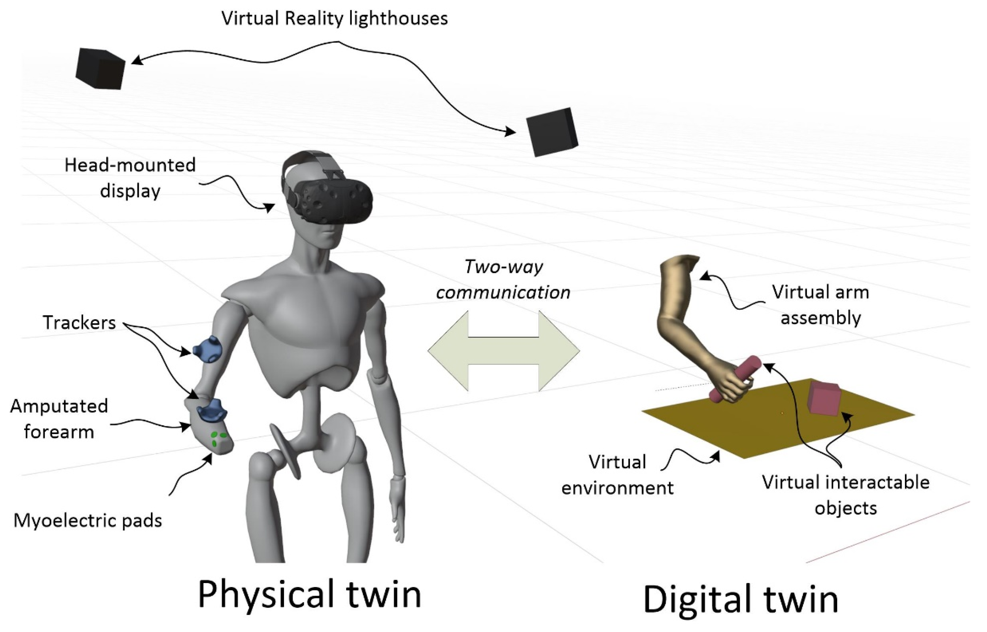
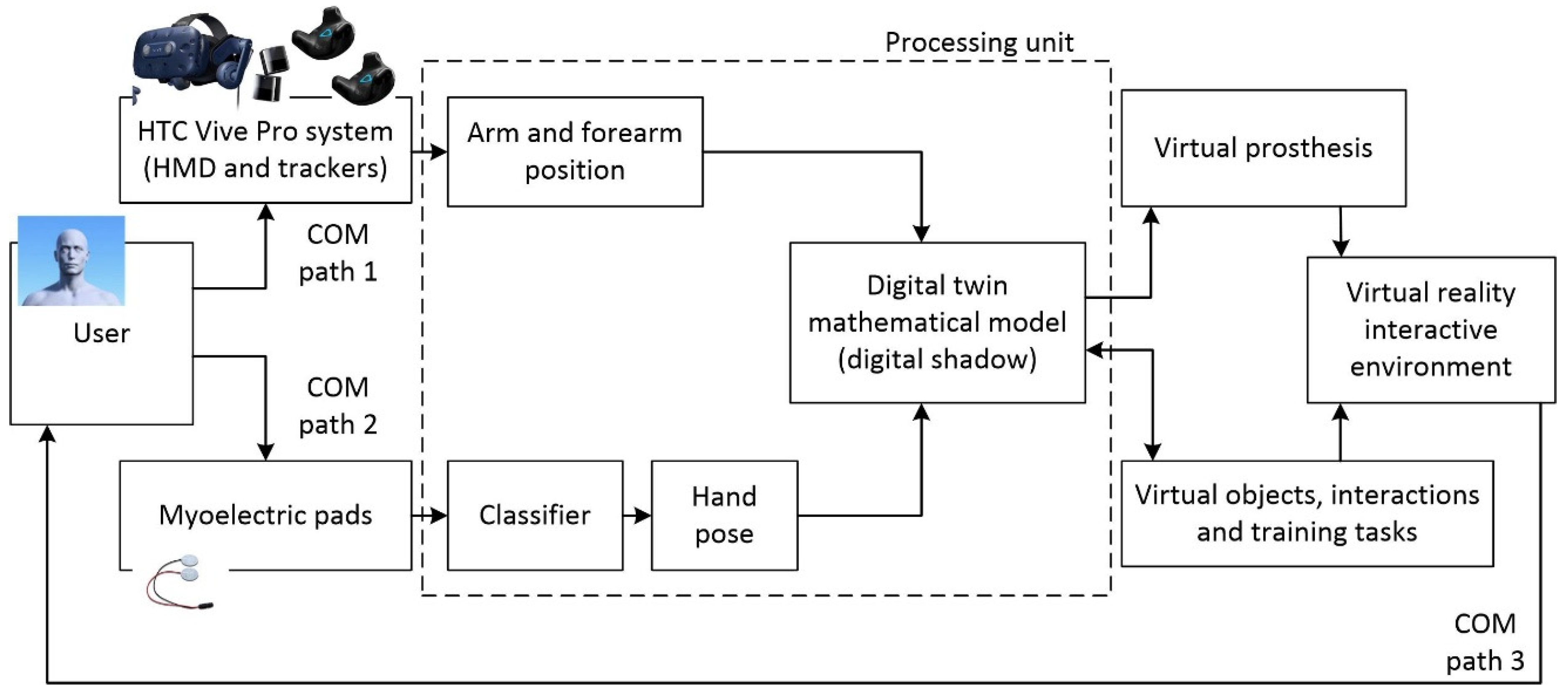
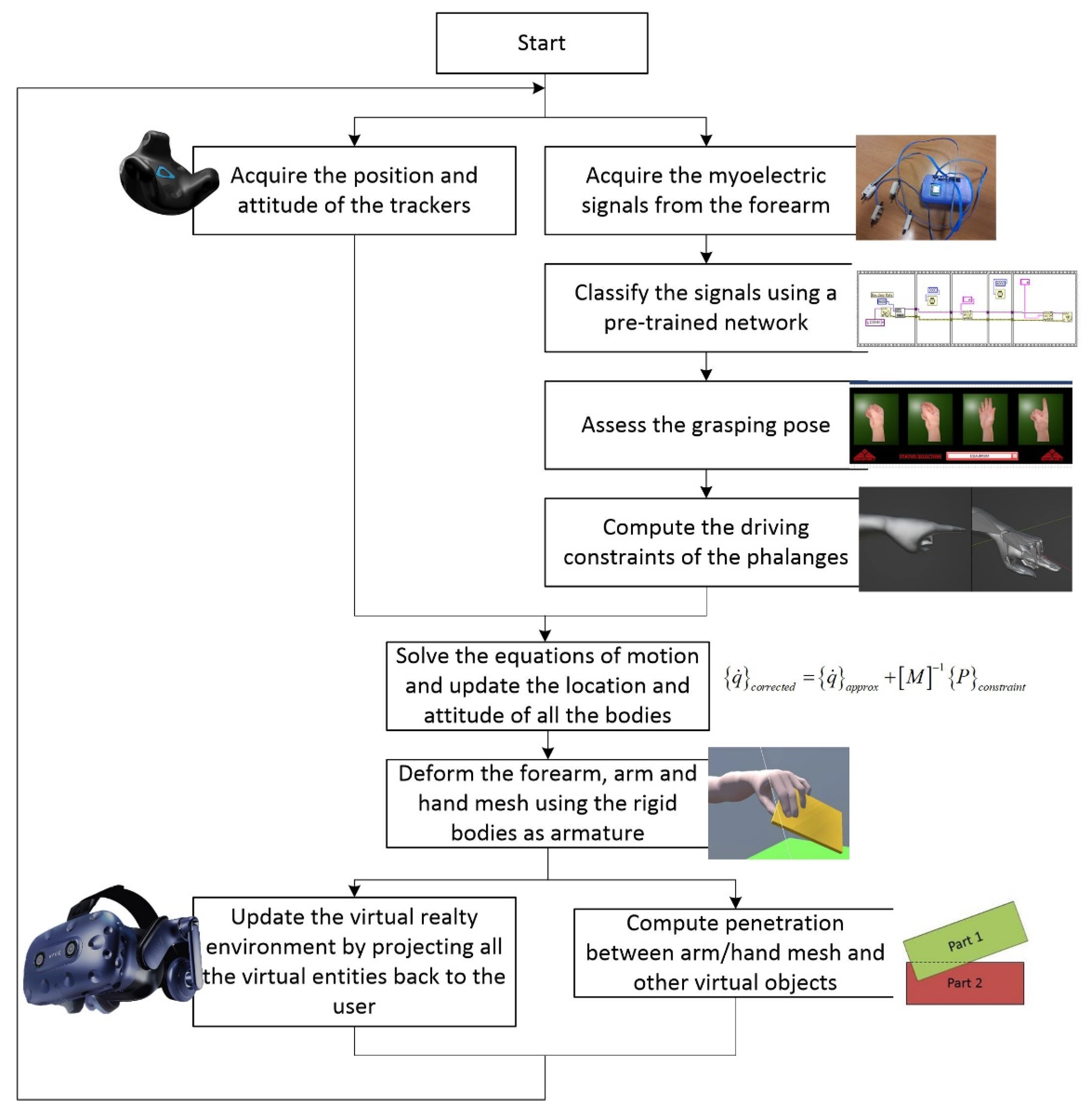
3. Digital Twin and Physical Twin Integration

The core of the proposed methodology is based on realizing a digital twin (DT) of the sensorized upper-limb prosthesis, namely its digital replica [21], which differs from a virtual prototype in three main aspects:
  • The DT communicates (preferably two-way) with its physical counterpart, namely the physical twin (PT) (exchanges information with real sensors);
  • The DT increases the information of its PT through mathematical models, providing real-time augmented information;
  • The DT is conceived to flank the PT throughout its life cycle.
DTs can easily interface with virtual and/or augmented reality environments, with immersive video technologies to facilitate (even immersive and highly realistic) communication with the user [22]. DTs have been adopted in different fields, from maintenance to product and process design, and, in recent years, researchers have been considering their adoption for training purposes [23], particularly in medicine [24,25,26]. Within this frame, we are focused on improving sensorized prosthesis dexterity to assess the strategic, but often disregarded, aspect of their long-term adoptability [8,9], moreover allowing customization and optimization for classifiers, electronics, and mechanical parts of the ensemble, before “wearing” the actual device. The virtual reality approach immerses the user in an environment where the prosthesis is highlighted, allows verification that the interfaced electronics correctly interpret his/her intent, and allows a series of manipulation and dexterity exercises to be performed as many times as is desired by the user.
Figure 1 shows a scheme of the DT-PT three communication paths (COM paths).
The first path delivers real-time information related to the arm positions in space with respect to the user’s head, in order to correctly collimate the virtual prosthesis on the upper limb. The second path regards the myoelectric sensors’ communication for the assessment of the hand grasping poses. The directions of both the first and second communication paths are from the physical to the digital twin, whilst the third path goes in the opposite direction to deliver visual feedback to the user. A data processing unit is in the middle of the three paths with the aim to synchronize information, ensure the real-time rendering and realism of the scene and, therefore, achieve training success.
To this aim, from the hardware side, we adopted the VIVE PRO virtual reality system (by HTC Corporation, New Taipei City, Taiwan) consisting of a head-mounted display, fixed infrared lighthouses, and crown-shaped trackers. On the helmet and on the trackers, there is a series of photodiodes that are activated by the lighthouses, and differences in illumination allow for determining their spatial position and attitude. From the software side, we developed the digital twin and the virtual scene using the UNITY platform (by Unity Technologies, San Francisco, CA, USA).
During training, the user is asked to wear the helmet and the two trackers using armbands (Figure 2). One tracker is firmly fixed on the arm, and the other on the remaining part of the forearm. Moreover, the user is asked to put on the myoelectric sensors (pads) and connect the whole system to the data processing workstation. The DT gathers information from the sensors of the PT and updates the immersive virtual scene using a specific procedure and computational algorithm (described in the next subsection). In the virtual environment, the virtual arm representing the sensorized prosthesis is placed according to the physical sensors. The virtual scenario is completed by other virtual objects classified as interactable entities that can come in contact and interact with the virtual hand. A set of instructions is also present in the virtual scene to guide the user to complete the training tasks.

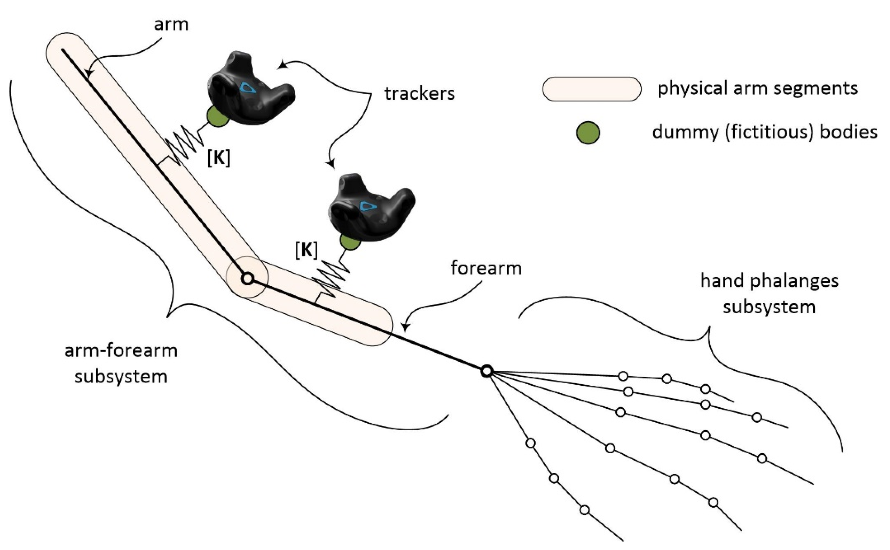
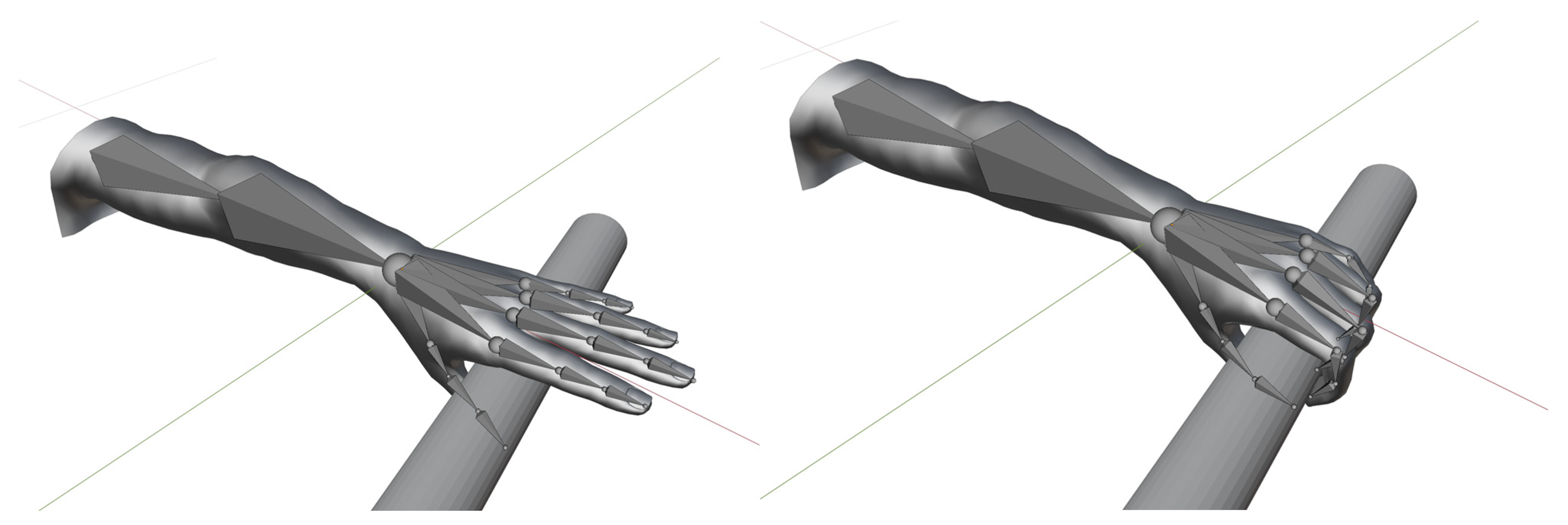
3.1. Virtual Prosthesis Dynamic Model and Trackers Interface

The role of the dynamic model is to accurately reproduce the motion dynamics of the virtual prosthesis, starting from the data of the trackers and the epidermal myoelectric sensors. The whole model can be broken down into two functional subassemblies. The first aims to replicate the dynamics of the arm and forearm on which the prosthesis is attached through an inverse dynamics model starting from the information acquired from the trackers. The second subassembly is needed to manage the movements of the grasping fingers (Figure 3).
The first subassembly consists of four rigid bodies. The first two, the main ones, are representative of the arm and forearm. They are connected by a spherical joint that replicates the functionality of the elbow in the distal portion of the arm. Although, from an anatomical point of view, the elbow joint does not have a simple spherical joint behaviour but a more complex elasto-kinematic characteristic [27], this assumption simplifies the complexity of the constraining equations without affecting the model’s reliability. This approach can easily be adapted to the presence of the trackers for controlling the relative motion between body segments.
The first subassembly then includes two other dummy (fictitious) bodies that are necessary to replicate the presence of trackers and efficiently transfer the information coming from them. These dummy bodies are not connected to the rest of the system by kinematic pairs but only by two elastic bushing elements. This solution has been chosen to obtain a reliable and computationally efficient model. This choice is often used as a smart compromise in overabundant systems [28]. In fact, the direct transfer of information from the trackers to the respective arm and forearm bodies (for example, by means of constraint equations that impose the equality of positions and attitudes) leads to an overabundant system of equations (too many constraining equations with respect to the degrees of freedom). This produces complications in the integration phase, and the solution of the dynamic system may fail or be extremely slow.
Considering that a body in a three-dimensional space has 6 degrees of freedom, the number of degrees of freedom of a system composed of two rigid bodies connected by a spherical joint is equal to 9, while the constraint equations from the trackers are 2 × 6 = 12. This leads to an overabundant system (12 > 9). Using bushing elements instead of kinematic constraints does not alter the number of the system’s number of degrees of freedom, which remains 9. From a mathematical point of view, a bushing element between two reference systems belonging to two different bodies can be written as
F = K Δ
where F is the vector of the generalised forces, K is a 6 × 6 stiffness matrix, and Δ is the vector of the generalised (linear and angular) displacements between the two reference frames. In other words, a bushing element behaves as a multidimensional spring force. By imposing a sufficiently high value on all the elements of the K matrix, the bushing element behaves in a similar way to a fixed constraint, ensuring the correct connection between the bodies. However, the intrinsic penalty approach of the bushing element allows the tolerance of slight measurement errors, tracker movements on anatomical segments, skin/cloth artefacts, and slight calibration errors without a significant impact on the solution of the equations.
The second subassembly is composed of 20 rigid bodies that schematise the various phalanges of the fingers (four bodies for each of the fingers). In this case, we connected the various segments using spherical joints. The second subassembly is a group of rigid bodies that, despite having an anatomical conformation, are not present in reality due to the presence of the amputated limb. Therefore, in this case, it is not included in the inverse dynamics problem. It is only used to simulate the movement of the prosthesis fingers and their interactions with objects in grasping and manipulation exercises. The movement of these rigid bodies is not controlled by trackers or other physical devices but is imposed by the interpretation of the myoelectric signals using a neural network classifier.
From a practical point of view, for each of the classifiable gestures, a series of time laws of the relative angles between the adjacent anatomical segments of the fingers is provided. They are imposed by means of driving constraints when the classifier recognises a pose with a sufficient degree of confidence. The speed at which these movements take place is calibrated according to the performance of the actual prosthesis in order to increase the sense of realism and proper delay. If the classifier does not return any posture update, the second subassembly actually behaves as a single rigid body because all the relative driving constraints enforce a stationary motion (zero relative velocities).
The two subassemblies are then connected to each other by a fixed constraint between the distal end of the forearm and the proximal end of the palm. Overall, the whole dynamic virtual arm system has
  • 24 rigid bodies (4 in the first subassembly and 20 in the second subassembly);
  • 17 kinematic constraints with 54 scalar equations (1 spherical joint between the arm and the forearm, 1 fixed constraint between the forearm and the palm, and 15 spherical joints between adjacent phalanges of the hand);
  • 57 motion constraints (6 scalar equations for each of the trackers and 3 scalar equations to control the relative rotation for each of the spherical constraints between adjacent phalanges);
  • 2 bushing elements (one for each of the trackers).
The dynamic model is built and solved according to the rigid multibody dynamics method, not using the global formulation [29] but adapting the sequential impulse formulation [30,31]. Studies in the literature have shown that this formulation is particularly suitable for solving dynamics problems in real-time and with interactivity requirements such as virtual and augmented reality environments [32]. The sequential impulse formulation is based on a two-step algorithm:
  • At the beginning, the equations of motion are solved by neglecting the kinematic constraints (free-body equations, considering only the external and internal forces applied to the bodies);
  • Subsequently, a series of impulses is applied to all the bodies, one at a time, sequentially and iteratively, to update their motion kinematics, fulfilling the constraint equations within a specific tolerance.
Considering a dynamic system where M is the mass matrix, q is the vector of the generalised coordinates, ψ is the vector of the constraint equations, and F e is the vector of the external forces and torques, in the first step of the formulation, the equations are solved neglecting the constraints:
M q ¨ a p p r o x = F e
where q ¨ a p p r o x is the vector of the approximated accelerations.
Approximated velocities and positions can be calculated as linear approximations from accelerations:
q ˙ a p p r o x = h q ¨ a p p r o x q a p p r o x = h q ˙ a p p r o x
where h is the integration time step, assumed as fixed.
Corrective impulses P c o n s t r a i n t generate variations according to Newton’s law of impulses:
M q ˙ c o r r e c t e d q ˙ a p p r o x = P c o n s t r a i n t
where q ˙ c o r r e c t e d is the vector of the corrected velocities that can be computed from Equation (4) as:
q ˙ c o r r e c t e d = q ˙ a p p r o x + M 1 P c o n s t r a i n t
Considering that impulses are exerted to satisfy constraints, it will result in the following:
P c o n s t r a i n t = ψ q T δ
where ψ q   is the Jacobian matrix of the constraint equations and δ is the vector of the Lagrange multipliers associated with the impulses.
Considering the time derivatives of the constraint equations, we obtain:
ψ = 0 d ψ d t = ψ q q ˙ + ψ t = 0 ψ q q ˙ c o r r e c t e d + ψ t = 0
Substituting the corrected accelerations in Equation (7):
ψ q q ˙ a p p r o x + M 1 ψ q T δ + ψ t = 0
Solving for Lagrange multipliers of the impulses:
δ = ψ q M 1 ψ q T 1 ψ q q ˙ a p p r o x + ψ t
and consequently, we find the impulses to be applied:
P c o n s t r a i n t = ψ q T δ
Correcting the accelerations and fulfilling the constraints requires a few iterations by repeating the algorithm.
The sequential impulse formulation is also particularly suitable for managing contacts, which are necessary to implement the general forms of interaction with virtual objects in the immersive scene. In particular, the collisions may be treated as penalty constraints. The generic not-overlapping condition between two bodies, C n can be written as:
C n = P A P B n A 0
where P A and P B are the closest points of two bodies that can come in contact and n A is the normal unit vector of the body shape at P A .
Equation (11) can be written at the velocity level as:
d C n d t = C ˙ n = d P A P B d t n A + P A P B d n A d t 0
The Baumgarte scheme [33] can be used to push the bodies apart when they overlap. The velocity constraint is augmented with a feedback term proportional to the penetration depth:
C ˙ n + β C n = 0
where β is a tunable scalar parameter which governs the speed of the penetration resolution. Equation (13) is then appended to the vector ψ and treated as a generic constraint.
Therefore, the complete procedure from the acquisition of the signals to the solution of the digital twin model to the integration with the virtual reality environment can be summarised in Figure 4.
In summary, the proposed procedure starts with the acquisition of the signals from the trackers and the myoelectric pads. From the former, the information about the position and attitude of the trackers is extracted, and from the latter, the electrical potential differences are extracted and then transferred to the classifier. The classifier interprets the patterns and returns the most likely grasping posture. With this posture, the driving constraints on the spherical joints are updated to move the phalanges accordingly. The data of the position and the attitude of the trackers and of the driving constraints on the phalanges are then transferred to the sequential impulse solver that integrates the equations. Once resolved, the updated positions and attitudes of all rigid bodies of the model are known.
The arm/hand mesh is congruently deformed starting from the position of the rigid bodies that work as a skeleton in the skinning mesh approach, a common strategy in computer graphics [34,35] and which is discussed in the next subsection of the paper. The updated arm model, as well as the position of all the other virtual bodies in the training scene, are then updated in the virtual reality environment. Knowing the position of the polygons in the arm mesh, it is possible to calculate the interpenetrations between the human virtual arm and all the other virtual objects in the scene, which are then returned to the solver for the next integration step. The entire algorithm must be completed within a single visualisation frame to ensure synchronism between the real scene and the virtual model, in order to have the DT properly collimated with the PT.

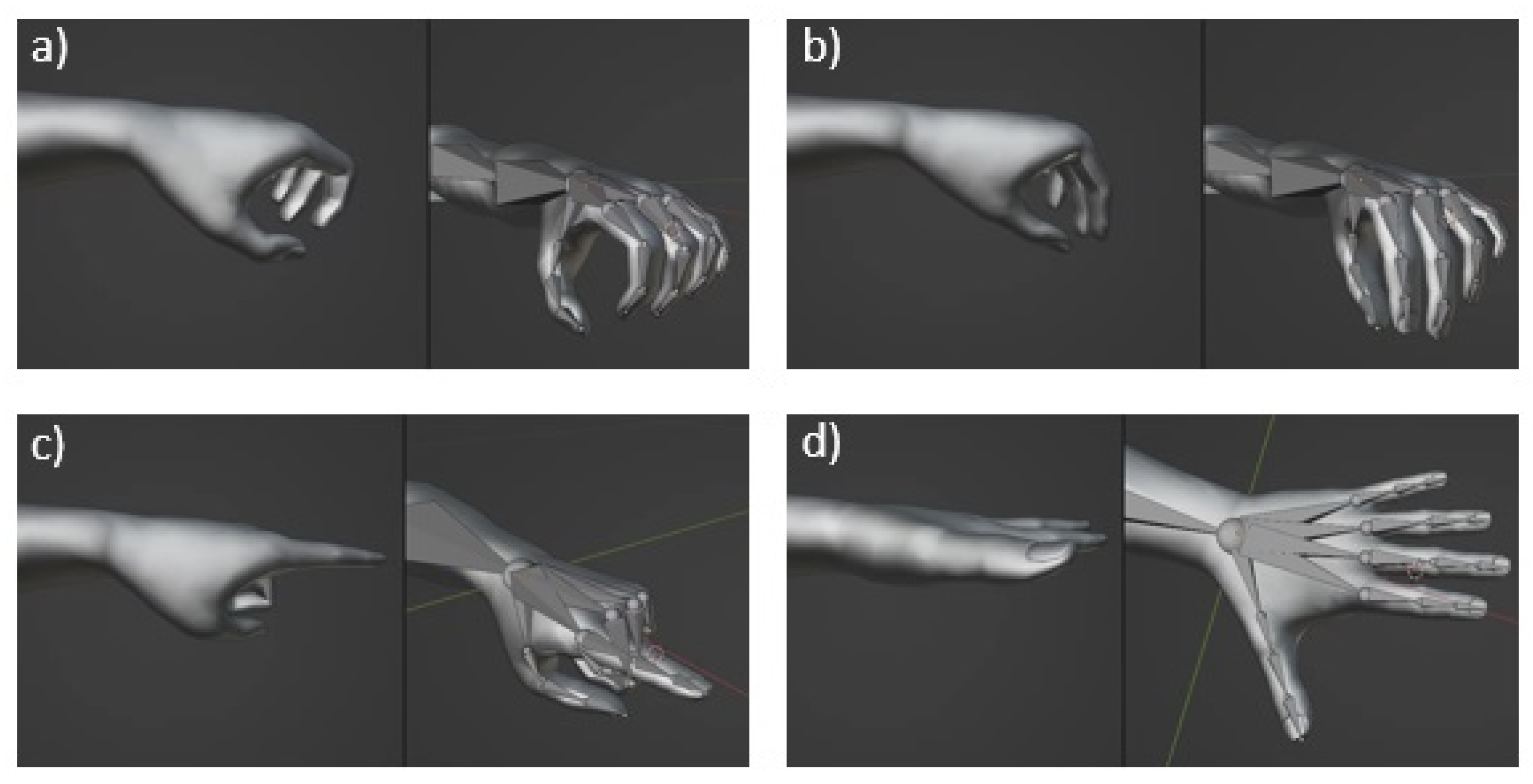
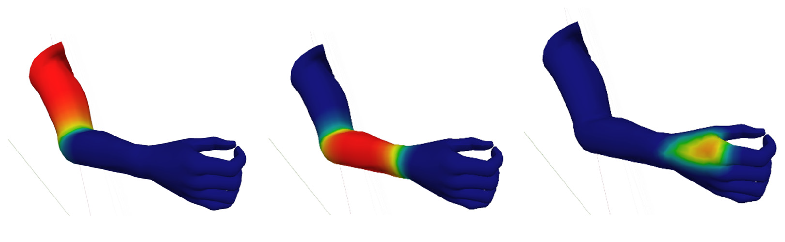
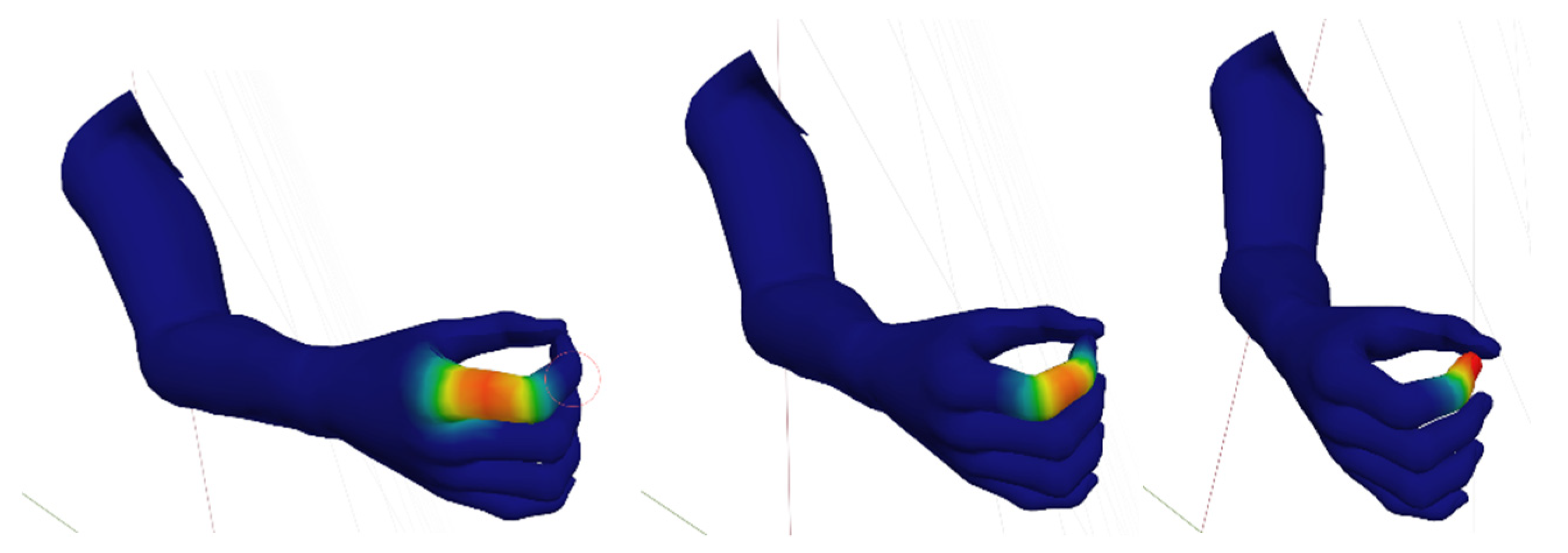
3.2. Arm and Hand Mesh Skinning

Mesh skinning is a technique used in computer graphics to animate and deform a 3D model [36]. The basic idea is to use a skeleton, or a hierarchical set of interconnected bones, to represent the underlying structure of a character. The actual 3D model (mesh) is then deformed based on the movement of these bones, allowing for realistic and dynamic character animations. When a bone moves, the mesh nodes are more or less attracted depending on the applied weight. If a bone has a weight 1 on a mesh node, it means that the node rigidly moves with the bone (it has the same spatial transformation). If a bone has a weight 0 on a mesh node, it means that the node is not influenced by the movement of the bone. A weight between 0 and 1 means that the actual movement of the node is blended between the movements of two or more bones. By using mesh skinning, the deformation of the mesh can be smooth and very realistic.
In the DT, the arm, forearm, and hand multibody model work as the skeleton of bones, and the anatomical shape works as the deformable mesh (Figure 5). The entire virtual deformable arm is a mesh with 4446 faces and 2506 nodes. This choice is a good compromise between accuracy and computational effort. Each bone has a weight on the nodes of the mesh, and some examples of these weights are reported in Figure 6. It can be seen, as a general strategy, that the weight of the nodes between two joints is 1 and then decreases in the areas around the joints themselves where the actual deformations occur.

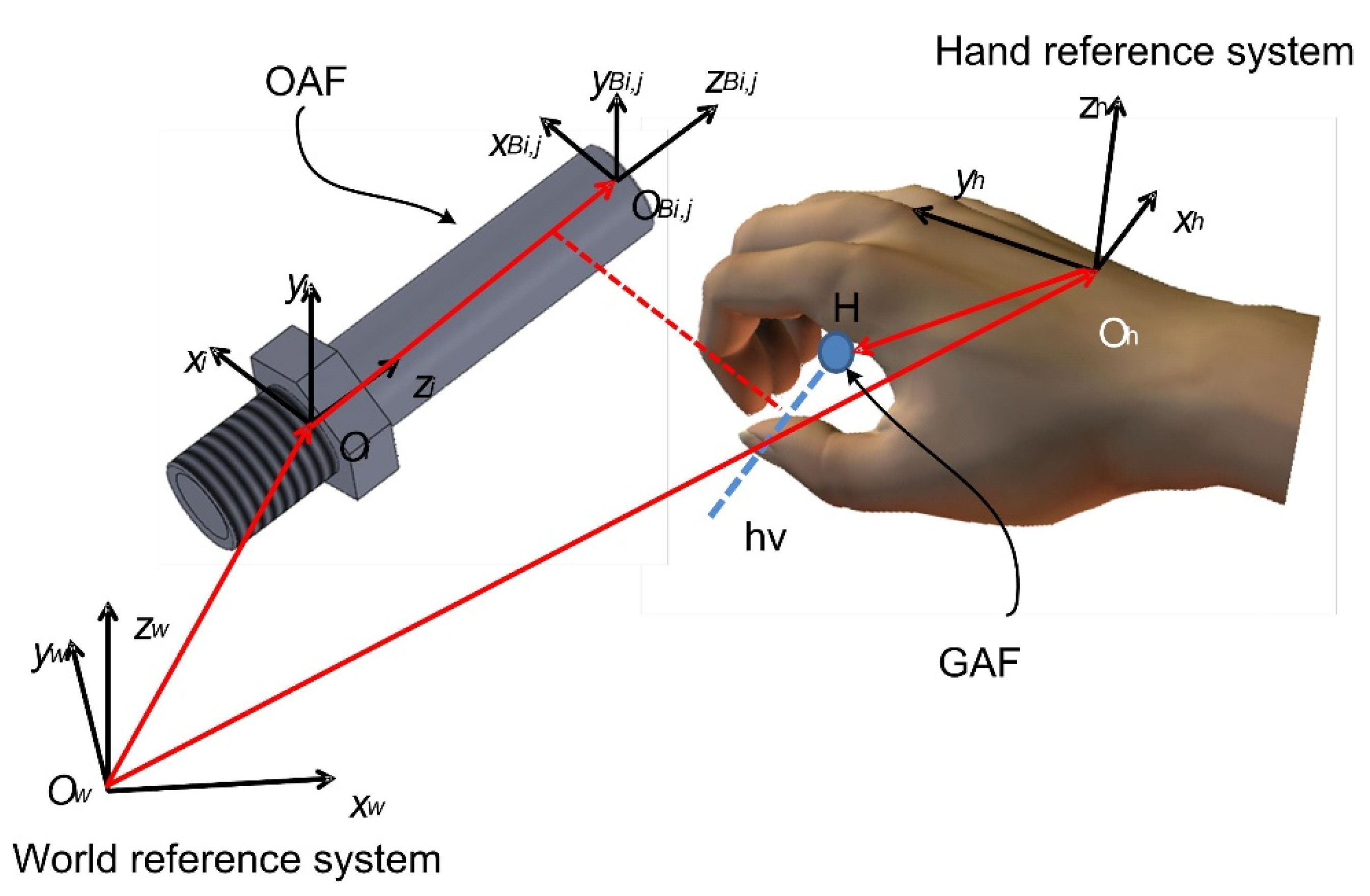
3.3. Implementation of Stable Grasping Actions

Although the contact interaction among all the virtual objects in the environment is always present to mimic the sense of realism, the grasping of the objects must be enforced using a more stable connection. In fact, rigid bodies whose kinematics is driven by external sources (such as the arm and the forearm) may produce excessive contact impulses that make it difficult to reach a stable grasping due to the rapid motion increments. For this reason, the grasping condition is enhanced using the grasping active feature/object active feature GAF/OAF methodology [37]. According to this methodology, a series of reference systems is assigned to the hand (GAF) and the bodies (OAF) that can be grasped (Figure 7). These reference systems work as communicators. The main steps of the methodology are:
  • when the user expresses the intention of grasping using a specific pose, the corresponding GAF is activated;
  • the relative position and attitude between the activated GAF and all the OAFs on the different objects in the scene are checked;
  • if the check produces a positive match (GAF and OAF are close and aligned), the grasping is confirmed, a constraint condition between the two reference systems is enforced, and the vector ψ is updated accordingly;
  • if the check produces a negative match (GAF and OAF are far and/or misaligned), the grasping is cancelled and the integration goes on without modifying the equations.
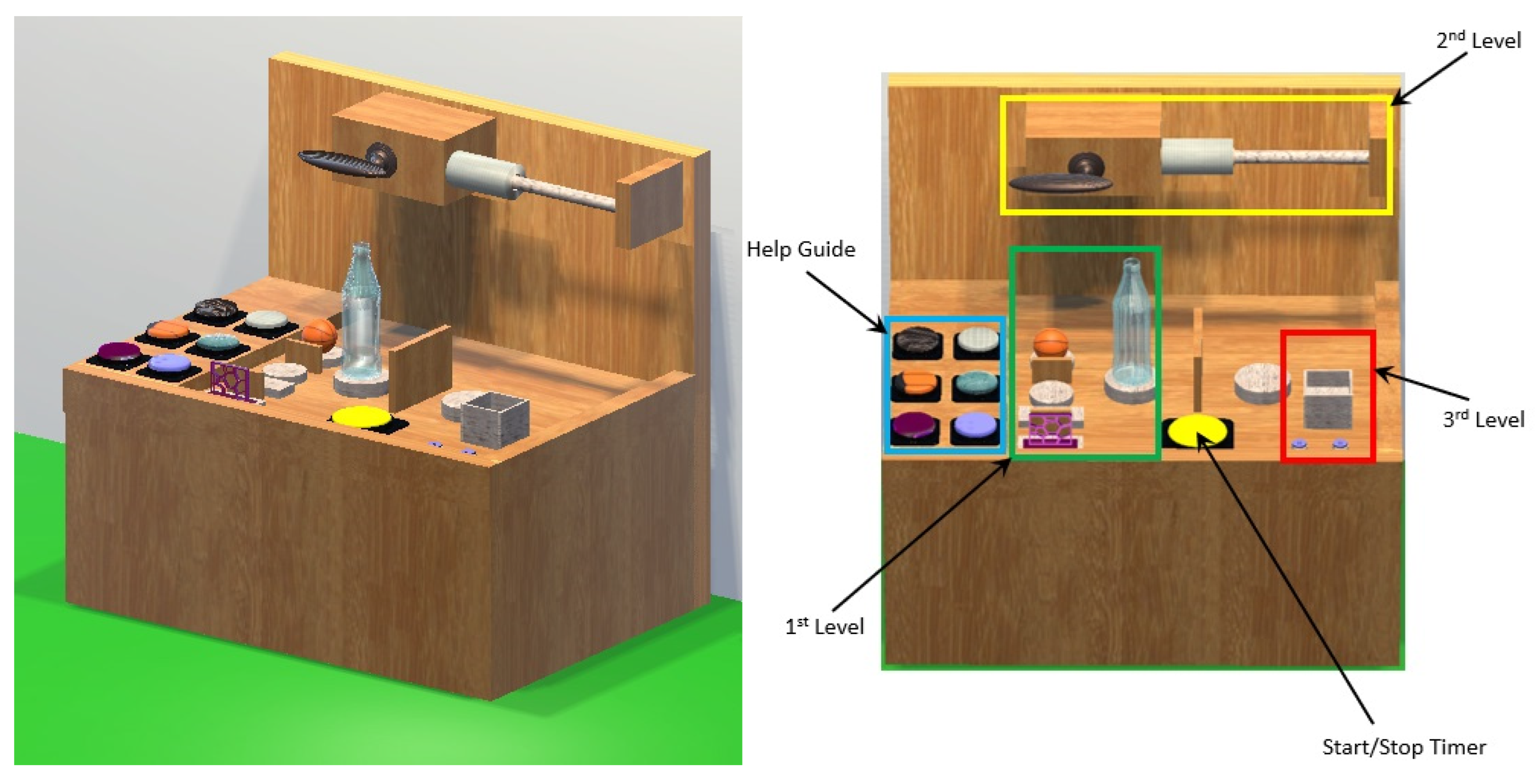
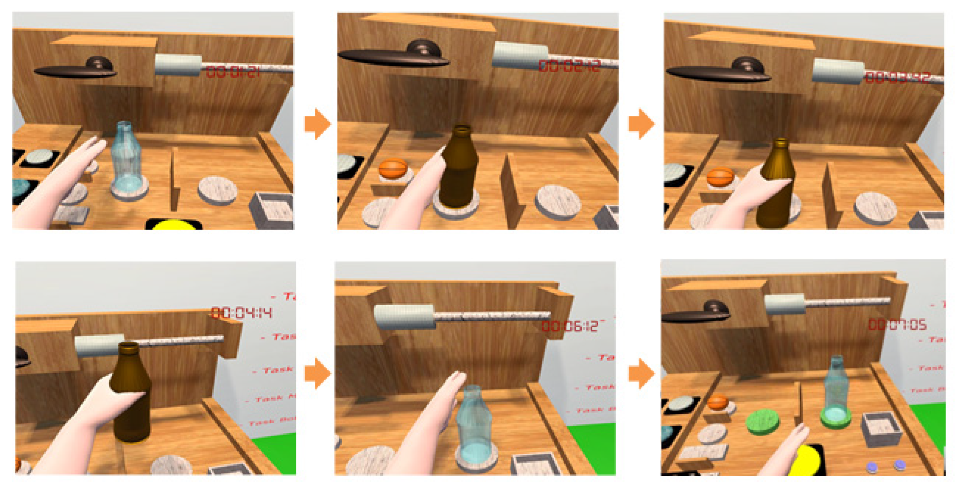
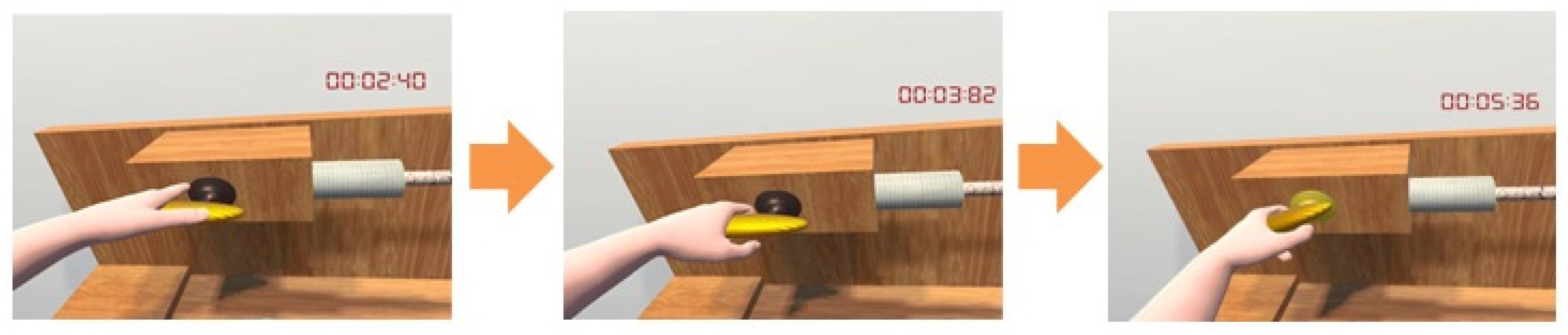
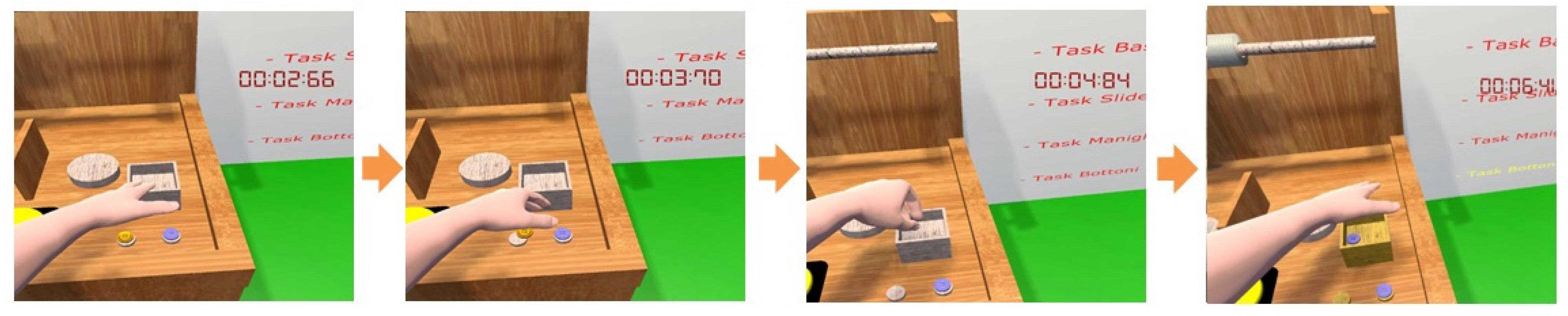
Further specific details of the methodology can be found in the seminal paper [37].

4. Training Tasks

The training of the prosthesis is realized by:
  • Updating the meshed virtual arm driven by the user movements, according to the classification outputs from myoelectric signal data, as for the actual prosthesis;
  • Implementing a series of grasping and manipulation exercises to improve the dexterity, according to the Southampton Hand Assessment Procedure (SHAP) [38], with the implementation of a virtual replica of the operations (named the VR-SHAP test).
The training tasks are based on the recognition of four main hand gestures, which are the power grip (grasp an object with all fingers), the three-finger grip (grasp with thumb, index and middle finger only), the pointing finger, and the flat hand, as shown in Figure 8.
In particular, the SHAP is useful for evaluating both impaired natural hands and prostheses. It involves a timed assessment consisting of 12 abstract object tasks and 14 daily living activities. The functionality profiles, derived from the timed tasks, work as metrics for assessing a subject’s (dis)ability, by providing an objective appraisal of the subject’s functional level, with the advantage of quantifying impairments in a single test rather than using relative improvement measures. Moreover, the SHAP can assess the effectiveness of a prosthetic end-effector and its controller by focusing on the user’s performance and can allow for tracking patients’ rehabilitation progress. This approach helps to highlight functional differences between several prosthetic devices and appropriate control schemes, while providing a contextual measure and comparison of hand function.
On the basis of the aforementioned four main hand poses (recognized by the classifier), we implemented six compatible tasks naming the procedure the Virtual Reality Southampton Hand Assessment Procedure (VR-SHAP). The procedures in VR-SHAP (Figure 9) are divided into three difficulty levels, as discussed in the following.
In the first level of difficulty, the user is asked to grasp an object, such as a bottle, a ball, or a plate, and place it on a base overcoming an obstacle (a barrier). The bottle and the ball are grasped through the power grip (Figure 10), the plate through the three-finger grip.
The second level of difficulty involves the rotation of a handle and the movement of a cylindrical slider along a guide up to a final target. The task involves the elbow rotation and the power grip pose. For the handle (Figure 11), the rotation is considered accomplished when the angle between the handle rotation axis and a reference direction is less than 5 degrees.
The third level of difficulty consists of inserting small objects (buttons) into a box (Figure 12). This task is classified with a higher level of difficulty because, due to the reduced size of the objects to be manipulated, greater precision and skill are required by the user.
The start and finish of all the tasks are managed by pressing a start or stop button using the pointing finger pose, and the execution time is used to evaluate the performance. The hand/objects grasping is implemented by means of the aforementioned OAF/GAF methodology for a stable grip, whilst the simple interaction is based on 3D contacts detected by means of mesh colliders adopting the corresponding equations (Equation (13)) of the sequential impulse solver.
The adopted VR-SHAP assessment is scored according to the index of functionality (IOF) algorithm [38], by considering the square sum of all the scores of the performed tasks and, ranging from zero (poor performance) to 100 (excellent performance). According to this approach, the overall score d of the tests can be assessed with the formula:
d = i = 1 k z i 2
where z i is the score of the i -th task and k is the number of executed tasks. The score of each task is computed using:
z i = x i x ˜ i s i
where x i is the time to complete the i -th task, x ˜ i is the average time to complete the i -th task of the reference sample, and s i is the standard deviation of the time measured for the i -th task of the reference sample;
The average and standard deviation of times, for evaluating Equations (14) and (15), are reported in the next section, together with the results on usability in Table 1.

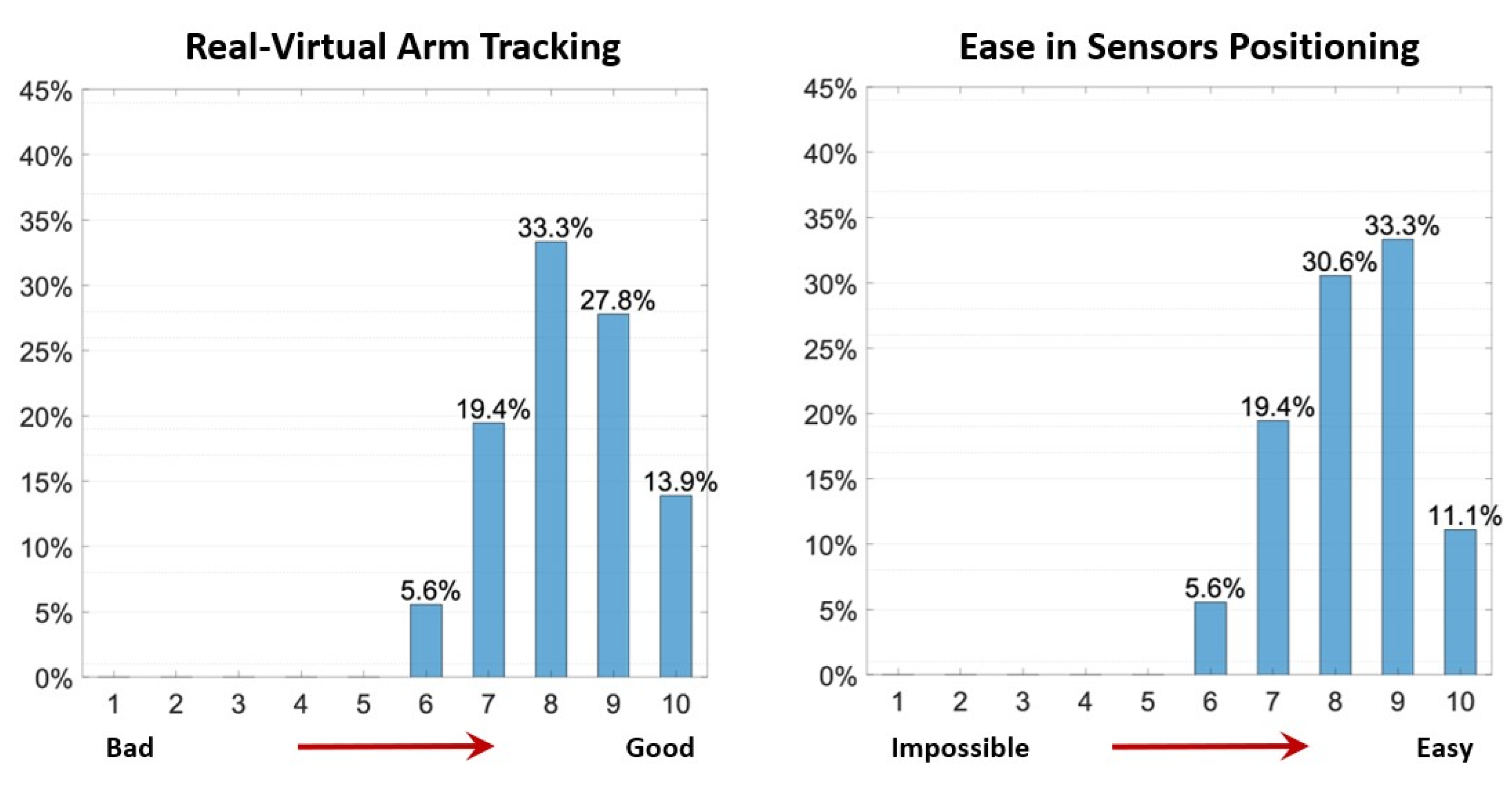
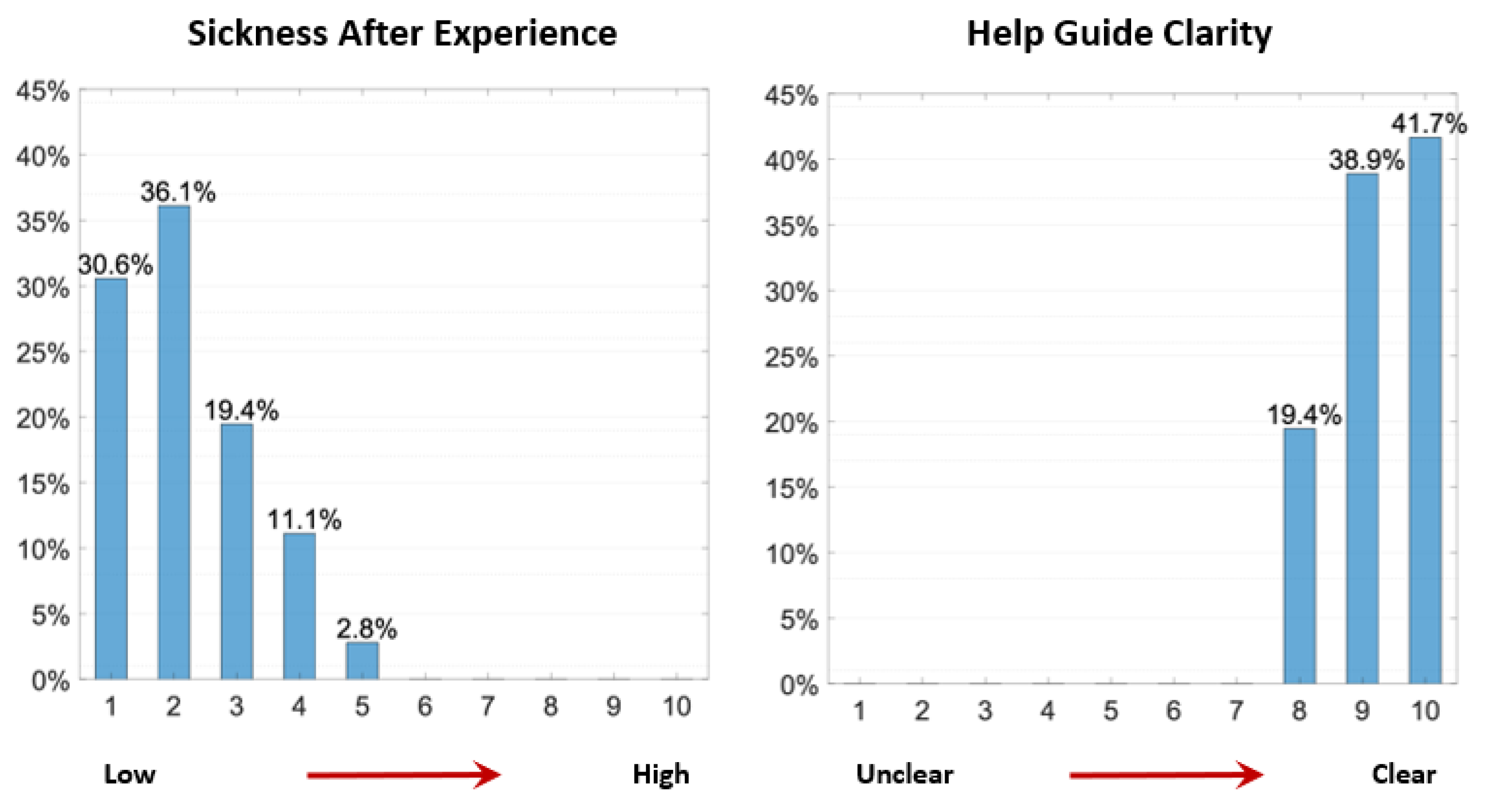
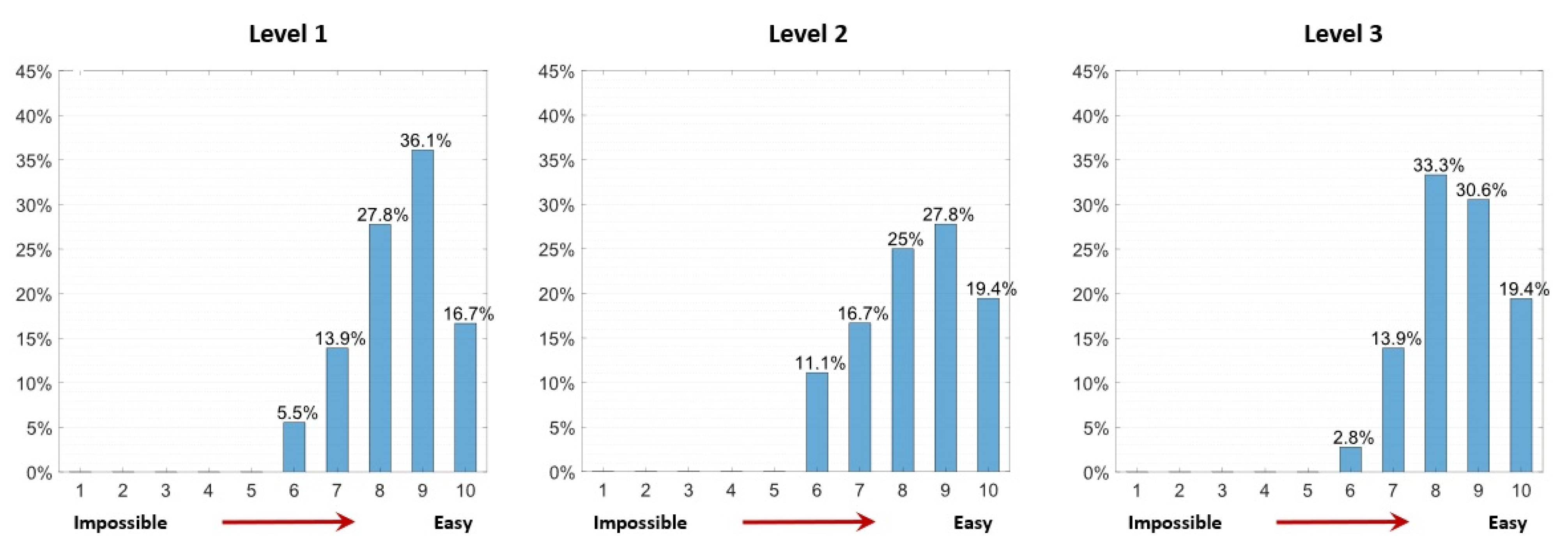
5. Usability Assessment Results

At the beginning of the test, the users were trained in the overall procedure (how to wear the trackers, the myoelectric sensors, and the head-mounted display, and how to manage the virtual reality environment), both by means of oral instructions and graphical guidelines. Then, the users were asked to repeat the overall procedure five times, so as to gain in familiarity with the system.
A preliminary usability analysis of the developed virtual environment was performed by means of a questionnaire collecting the degree of impact and the difficulties in understanding the guidelines, setup procedure, and scene interaction (also in terms of real-time aspects, excluding the classification performances), statistically executed on thirty-six users, evenly gender distributed, and 20–50 years of age (mean value 30 years, standard deviation 8.5 years). These users were asked to assign a score of 0 to 10 (from very bad/difficult to very good/easy condition). According to the results reported in Figure 13, the usability analysis reports a relatively high level of scores, testifying to an adequate implementation of the DT simulative model and communication interfaces.
Moreover, users were asked to execute the VR-SHAP tasks following the procedure described in the previous section. The results in terms of the average time and standard deviation are reported in Table 1. These values are then used for evaluating the VR-SHAP test according to Equations (14) and (15).
At the end of all of the tests, the users were asked to rate the level of difficulty encountered in performing the tasks and provide reasons for their ratings.
As we could expect (Figure 14), the first-level tasks show a high easiness rating, due to there being fewer constraints for the implementation of the OAF method. Despite the higher difficulty of the third-level tasks (due to the reduced size of the objects to grasp), the easiness rating was higher than that of the second-level tasks. We argue that this can be related to the reduced number of degrees of freedom of the virtual prosthesis wrist which makes the reaching of large rotations more difficult.
To score the clarity of guidelines and the general impact with virtual reality (related to the sensations experienced throughout the immersion in the virtual environment), users were asked to rate the (dis)comfort of their experience. According to the results (Figure 15), the guidelines were considered very clear (the application being as independent as possible from the operator), with the sickness directly correlated with the users’ age. In general, the immersive experience was well tolerated by all the users without excessive discomfort.
Regarding the setup, a higher difficulty was reported in the positioning of the second tracker (that may interfere with the myoelectric sensors’ mounting). Moreover, some users initially reported some issues with the task involving handle rotation, so that we facilitated the self-alignment of the handle with the virtual hand in running, reducing the torsional stiffness of the spring attached to the handle. Some movements and interactions were also improved and optimized to reduce the gap between the DT and the PT. Finally, the initial discomfort perceived by some users at the end of the virtual experience was reduced by softening the colours used in the virtual environment.

6. Conclusions

We report a complete virtual environment based on digital twin resources, including hardware and software issues, to support the amputee’s training of an upper-limb sensorized prosthesis. The hardware consists of the HTC Vive Pro system and the software is built in-house using the UNITY development platform. The digital twin is developed using multibody dynamics techniques and the sequential impulse solver formulation that allows for a robust, accurate, and reliable solution of the equation of motion, including contact dynamics.
The overall system was tested with users performing several training tasks including the gesture intent recognition and reproducing most of the SHAP test assessment methodology. According to the usability tests, the training tasks appear easy to use, and very limited pre-training and setting are needed. The dexterity of the user, measured according to the test KPIs, increases over time with practice, confirming the procedure’s efficiency. The usability analysis highlighted the good results (even in this initial phase), suggesting possible improvements both for the configuration phase of the sensors and in the implementation of the interactive environment.
In general, this study demonstrates the validity of training tools developed using virtual reality, interactive environments, and digital twins for medical rehabilitation purposes. Future improvements of the digital twin can regard force feedback systems to enforce correspondence with reality with a fully two-way communication between the physical and digital twins. The research will be completed by an extensive experimental campaign to evaluate the medium- and long-term effectiveness of using the proposed virtual environment as a training aid in comparison with the standard procedure. At present, we have developed a single digital twin, which, as mentioned in the introduction, adapts to the iHannes prosthesis produced by the INAIL prosthetic centre. However, we believe that the approach and the virtual environment can be fully generalizable by simply updating the geometrical models and the mathematical conditions for different poses and grips.

Author Contributions

Conceptualization, P.P.V.; methodology, M.C. and P.P.V.; software, A.C.; validation, A.C.; data curation, M.C. and A.C.; writing—original draft preparation, P.P.V., M.C. and A.C.; writing—review and editing, G.S. and P.P.V.; supervision, E.G.; project administration, E.G.; funding acquisition, G.S. All authors have read and agreed to the published version of the manuscript.

Funding

The project is partially funded by the Project PR19-PAS-P1—iHannes CUP N. J59C20001410005. Implementations and experimental tests were performed at the Joint Laboratory established within of the Project ECS 0000024 Rome Technopole, CUP E83C22003240001, NRP Mission 4 Component 2 Investment 1.5, funded by the European Union NextGenerationEU.

Data Availability Statement

Data are contained within the article.

Conflicts of Interest

The authors declare no conflicts of interest.

References

  1. Castellini, C. Upper limb active prosthetic systems-overview. In Wearable Robotics: Systems and Applications; Academic Press: Cambridge, MA, USA, 2019; pp. 365–376. [Google Scholar]
  2. Controzzi, M.; Cipriani, C.; Carrozza, M. Design of artificial hands: A review. In Springer Tracts in Advanced Robotics; Springer: Berlin/Heidelberg, Germany, 2014; pp. 219–246. [Google Scholar]
  3. Vujaklija, I.; Farina, D.; Aszmann, O.C. New developments in prosthetic arm systems. Orthop. Res. Rev. 2016, 8, 31–39. [Google Scholar] [CrossRef] [PubMed]
  4. Bouwsema, H.; van der Sluis, C.K.; Bongers, R.M. Learning to control opening and closing a myoelectric hand. Arch. Phys. Med. Rehabil. 2010, 91, 1442–1446. [Google Scholar] [CrossRef] [PubMed]
  5. D’anna, E.; Valle, G.; Mazzoni, A.; Strauss, I.; Iberite, F.; Patton, J.; Petrini, F.M.; Raspopovic, S.; Granata, G.; Di Iorio, R.; et al. A closed-loop hand prosthesis with simultaneous intraneural tactile and position feedback. Sci. Robot. 2019, 4. [Google Scholar] [CrossRef] [PubMed]
  6. Pistohl, T.; Cipriani, C.; Jackson, A.; Nazarpour, K. Abstract and proportional myoelectric control for multi-fingered hand prostheses. Ann. Biomed. Eng. 2013, 41, 2687–2698. [Google Scholar] [CrossRef]
  7. Pylatiuk, C.; Schulz, S.; Döderlein, L. Results of an Internet survey of myoelectric prosthetic hand users. Prosthetics Orthot. Int. 2007, 31, 362–370. [Google Scholar] [CrossRef]
  8. Biddiss, E.; Chau, T. Upper limb prosthesis use and abandonment: A survey of the last 25 years. Prosthet. Orthot. Int. 2007, 31, 236–257. [Google Scholar] [CrossRef]
  9. Bicchi, A. Hands for dexterous manipulation and robust grasping: A difficult road toward simplicity. IEEE Trans. Robot. Autom. 2000, 16, 652–662. [Google Scholar] [CrossRef]
  10. Bunderson, N.E. Real-Time Control of an Interactive Impulsive Virtual Prosthesis. IEEE Trans. Neural Syst. Rehabil. Eng. 2013, 22, 363–370. [Google Scholar] [CrossRef]
  11. Hargrove, L.; Miller, L.; Turner, K.; Kuiken, T. Control within a virtual environment is correlated to functional outcomes when using a physical prosthesis. J. NeuroEngineering Rehabil. 2018, 15, 1–7. [Google Scholar] [CrossRef]
  12. Barresi, G.; Marinelli, A.; Caserta, G.; de Zambotti, M.; Tessadori, J.; Angioletti, L.; Boccardo, N.; Freddolini, M.; Mazzanti, D.; Deshpande, N.; et al. Exploring the Embodiment of a Virtual Hand in a Spatially Augmented Respiratory Biofeedback Setting. Front. Neurorobotics 2021, 15. [Google Scholar] [CrossRef]
  13. Lambrecht, J.M.; Pulliam, C.L.; Kirsch, R.F. Virtual reality environment for simulating tasks with amyoelectric prosthesis: An assessment and training tool. J. Prosthet. Orthot. 2011, 23, 89–94. [Google Scholar] [CrossRef] [PubMed]
  14. Semprini, M.; Boccardo, N.; Lince, A.; Traverso, S.; Lombardi, L.; Succi, A.; Canepa, M.; Squeri, V.; Saglia, J.A.; Ariano, P.; et al. Clinical evaluation of Hannes: Measuring the usability of a novel polyarticulated prosthetic hand. In Tactile Sensing, Skill Learning, and Robotic Dexterous Manipulation; Academic Press: Cambridge, MA, USA, 2022; pp. 205–225. [Google Scholar]
  15. Di Domenico, D.; Marinelli, A.; Boccardo, N.; Semprini, M.; Lombardi, L.; Canepa, M.; Stedman, S.; Della Casa, A.B.; Chiappalone, M.; Gruppioni, E.; et al. Hannes Prosthesis Control Based on Regression Machine Learning Algorithms. In Proceedings of the IEEE International Conference on Intelligent Robots and Systems, Prague, Czech Republic, 27 September–1 October 2021. [Google Scholar]
  16. Weiner, P.; Starke, J.; Hundhausen, F.; Beil, J.; Asfour, T. The KIT Prosthetic Hand: Design and Control. In Proceedings of the IEEE International Conference on Intelligent Robots and Systems, Madrid, Spain, 1–5 October 2018. [Google Scholar]
  17. Cipriani, C.; Controzzi, M.; Carrozza, M. The SmartHand transradial prosthesis. J. NeuroEngineering Rehabil. 2011, 8, 1–14. [Google Scholar] [CrossRef] [PubMed]
  18. Zecca, M.; Micera, S.; Carrozza, M.C.; Dario, P. Control of Multifunctional Prosthetic Hands by Processing the Electromyographic Signal. Crit. Rev. Biomed. Eng. 2017, 45, 383–410. [Google Scholar] [CrossRef] [PubMed]
  19. Costantini, G.; Todisco, M.; Casali, D.; Carota, M.; Saggio, G.; Bianchi, L.; Quitadamo, L. SVM classification of EEG signals for brain computer interface. In Proceedings of the Neural Nets WIRN09, Vietri sul Mare, Italy, 28–30 May 2009. [Google Scholar]
  20. Riillo, F.; Quitadamo, L.R.; Cavrini, F.; Saggio, G.; Pinto, C.A.; Pastò, N.C.; Gruppioni, E. Evaluating the influence of subject-related variables on EMG-based hand gesture classification. In Proceedings of the IEEE International Symposium on Medical Measurements and Applications (MeMeA), Jeju, Republic of Korea, 14–16 June 2014. [Google Scholar]
  21. Grieves, M. Digital Twin of Physical Systems: Opportunities and Challenges. In Proceedings of the ASME 2002 International Mechanical Engineering Congress and Exposition, New Orleans, LA, USA, 17–22 November 2002. [Google Scholar]
  22. Merienne, F. Human factors consideration in the interaction process with virtual environment. Int. J. Interact. Des. Manuf. 2000, 4, 83–86. [Google Scholar] [CrossRef]
  23. Martínez-Gutiérrez, A.; Díez-González, J.; Verde, P.; Perez, H. Convergence of Virtual Reality and Digital Twin technologies to enhance digital operators’ training in industry 4.0. Int. J. Hum. Comput. Stud. 2023, 180, 103136. [Google Scholar] [CrossRef]
  24. Kamel, F.A.H.; Basha, M.A. Effects of Virtual Reality and Task-Oriented Training on Hand Function and Activity Performance in Pediatric Hand Burns: A Randomized Controlled Trial. Arch. Phys. Med. Rehabil. 2021, 102, 1059–1066. [Google Scholar] [CrossRef]
  25. Lam, J.-F.; Gosselin, L.; Rushton, P.W. Use of Virtual Technology as an Intervention for Wheelchair Skills Training: A Systematic Review. Arch. Phys. Med. Rehabil. 2018, 99, 2313–2341. [Google Scholar] [CrossRef]
  26. Rathinam, C.; Mohan, V.; Peirson, J.; Skinner, J.; Nethaji, K.S.; Kuhn, I. Effectiveness of virtual reality in the treatment of hand function in children with cerebral palsy: A systematic review. J. Hand Ther. 2018, 32, 426–434.e1. [Google Scholar] [CrossRef]
  27. Kecskeméthy, A.; Weinberg, A. An Improved Elasto-Kinematic Model of the Human Forearm for Biofidelic Medical Diagnosis. Multibody Syst. Dyn. 2005, 14, 1–21. [Google Scholar] [CrossRef]
  28. Valentini, P.P. Effects of the dimensional and geometrical tolerances on the kinematic and dynamic performances of the Rzeppa ball joint. Proc. Inst. Mech. Eng. Part D J. Automob. Eng. 2013, 228, 37–49. [Google Scholar] [CrossRef]
  29. Mariti, L.; Belfiore, N.P.; Pennestrì, E.; Valentini, P.P. Comparison of Solution Strategies for Multibody Dynamics Equations. Int. J. Numer. Methods Eng. 2011, 88, 637–656. [Google Scholar] [CrossRef]
  30. Mirtich, B.V. Impulse-Based Dynamic Simulation of Rigid Body Systems. Ph.D. Thesis, University of California, Berkeley, CA, USA, 1996. [Google Scholar]
  31. Schmitt, A.; Bender, J. Impulse-based dynamic simulation of multibody systems: Numerical comparison with standard methods. In Proceedings of the Automation of Discrete Production Engineering, Sozopol, Bulgaria, 21–23 September 2005; pp. 324–329. [Google Scholar]
  32. Valentini, P.P.; Pezzuti, E. Interactive Multibody Simulation in Augmented Reality. J. Theor. Appl. Mech. 2010, 48, 733–750. [Google Scholar]
  33. Baumgarte, J. Stabilization of constraints and integrals of motion in dynamical systems. Comput. Methods Appl. Mech. Eng. 1972, 1, 1–16. [Google Scholar] [CrossRef]
  34. Rumman, N.A.; Fratarcangeli, M. State of the art in skinning techniques for articulated deformable characters. In Proceedings of the Eleventh International Conference on Computer Graphics Theory and Application, GRAPP 2016, Rome, Italy, 27–29 February 2016; Part of the Eleventh Joint Conference On Computer Vision, Imaging and Computer Graphics Theory and Applications, VISIGRAPP 2016. SciTePress: Setubal, Portugal, 2016. [Google Scholar]
  35. Sujar, A.; Casafranca, J.J.; Serrurier, A.; Garcia, M. Real-time animation of human characters’ anatomy. Comput. Graph. 2018, 74, 268–277. [Google Scholar] [CrossRef]
  36. de Aguiar, E.; Ukita, N. Representing mesh-based character animations. Comput. Graph. 2014, 38, 10–17. [Google Scholar] [CrossRef]
  37. Valentini, P.P. Interactive virtual assembling in augmented reality. Int. J. Interact. Des. Manuf. 2009, 3, 109–119. [Google Scholar] [CrossRef]
  38. Light, C.M.L.; Chappell, P.H.; Kyberd, P. Assessment of hand functionality using the Southampton Hand Assessment Procedure. In Proceedings of the 12th World Congress of the International Society for Prosthetics and Orthotics, Vancouver, BC, Canada, 29 July–3 August 2007. [Google Scholar]
Figure 1. Communication paths between the physical and the digital twins in the training environment. The user communicates with the digital twin through the virtual reality trackers (COM Path 1) and the myoelectric sensors (COM Path 2). The digital twin, through the mathematical model, returns an updated virtual environment by means of the head-mounted display (COM Path 3).
Algorithms 17 00035 g001
Figure 2. Physical and digital twins of the VR training environment. The physical twin includes the kinematic sensors (trackers), the myoelectric sensors, and the head-mounted display. The digital twin is driven by the multibody dynamic model able to simulate real-time physics including collisions.
Algorithms 17 00035 g002
Figure 3. Schematic overview of the dynamic model of the arm. The locations of the anchor points of the springs connecting the trackers and the body segment are computed during initial calibration.
Algorithms 17 00035 g003
Figure 4. The proposed procedure to manage the dynamic behaviour of the prosthetic arm digital twin. Both communication paths from the physical sensors go to the multibody model that updates the position and attitude of all the objects in the virtual environment, according to an accurate physics simulation.
Algorithms 17 00035 g004
Figure 5. An example of the mesh skinning over rigid body rigging for the cylindrical grasping pose. The pyramidal bodies are the bones of the armature (the rigid bodies of the simulative model) and the anatomical mesh is the virtual morphable character.
Algorithms 17 00035 g005
Figure 6. Mesh node weights for the realistic skinning of the virtual arm. Red colour means a weight of 1 and blue colour a weight of 0. The higher the weight, the closer the movement of the mesh with respect to the bone.
Algorithms 17 00035 g006aAlgorithms 17 00035 g006b
Figure 7. An example of the OAF/GAF methodology for the cylindrical grip (adapted from [37]).
Algorithms 17 00035 g007
Figure 8. The four hand poses and the related skeleton and skinned mesh: (a) power grip, (b) three-finger grip, (c) pointing finger, and (d) flat hand.
Algorithms 17 00035 g008
Figure 9. VR-SHAP test implementation in the virtual environment. The tasks are divided into three groups, depending on the level of difficulty. A help guide, using virtual buttons, can be activated by the user during the execution of the tasks.
Algorithms 17 00035 g009
Figure 10. An example of the first level of the VR-SHAP test: the grasping and manipulation of a bottle. The user locates the bottle, grasps it, and then places it, stable, on a cylindrical base.
Algorithms 17 00035 g010
Figure 11. An example of the second level of the VR-SHAP test: the rotation of a handle. The user locates the handle, grabs it, and then rotates it of 45°.
Algorithms 17 00035 g011
Figure 12. An example of the third level of the VR-SHAP test: the manipulation of the buttons. The user locates the buttons, grabs one at time, and then releases them inside a box.
Algorithms 17 00035 g012
Figure 13. Usability analysis results about arm tracking (left) and ease in sensors’ positioning (right). Both the fidelity in tracking and the ease in wearing sensors scored high values, confirming the very good usability.
Algorithms 17 00035 g013
Figure 14. Usability analysis results of VR-SHAP tasks at different difficulty levels. The first-level tasks score a higher easiness due to their simplicity. The second-level tasks are reported to be more difficult due to the limited degrees of freedom of the prosthesis wrist.
Algorithms 17 00035 g014
Figure 15. Usability analysis results about the sickness after the experience (left) and the help guide clarity (right). The reported sickness level is very low and therefore most of the users tolerated the virtual environment. In the same way, the use of a graphical interface for the help guide was found very useful.
Algorithms 17 00035 g015
Table 1. Average and standard deviation time for the six tasks of VR-SHAP.
TaskAverage Time [s]Standard Deviation [s]Level of Difficulty
Bottle8.42.4Level 1
Ball7.23.2Level 1
Plate6.82.4Level 1
Handle6.04.0Level 2
Slider19.24.0Level 2
Buttons17.64.0Level 3
Disclaimer/Publisher’s Note: The statements, opinions and data contained in all publications are solely those of the individual author(s) and contributor(s) and not of MDPI and/or the editor(s). MDPI and/or the editor(s) disclaim responsibility for any injury to people or property resulting from any ideas, methods, instructions or products referred to in the content.

