

Following the Writer’s Path to the Dynamically Coalescing Reactive Chains Design Pattern

Abstract
1. Introduction
- (RQ1)
- (RQ2)
- Can we follow Wellhausen and Fiesser’s writer’s path [15] to write the new pattern step by step?
2. Writing Software Patterns
- A design pattern is a mid-level, (mostly) language-independent abstraction that guides the design of a subsystem.
- An idiom is a low-level language-specific abstraction that guides some aspects of both design and implementation.
- Pattern Name gives an evocative name for the pattern.
- Context describes the circumstances in which the problem occurs.
- Problem describes the specific problem to be solved.
- Forces describe why the problem is difficult to solve, identifying the often contradictory considerations that must be balanced to solve the problem.
- Solution describes how the solution to the problem works at an appropriate level of detail.
- Consequences describe what happens when a software designer applies the pattern. It gives both the possible benefits and liabilities of using the pattern.
- Explore the new pattern’s rationale and scope.We consider questions such as: Why should we write a new pattern? What is included in and excluded from its scope? What concrete examples do we have that we can examine? We then state a crisp definition for the scope.
- Examine existing solutions.We consider the answers to the questions from the previous step and discuss the solutions with others. We seek to determine what is common across all the solutions and what is variable among the solutions (i.e., holds for only some of the solutions).We briefly summarize the general solution, focusing on its essence. We collect a list of possible names for the pattern. We also list any clever ideas identified in the solutions for later consideration, even if they are not essential to the solution.
- Describe the problem that leads to the solution.We strive to state this description in one sentence. We must be careful to separate the problem from its solution and make sure that the solution actually solves the problem.
- Consider the consequences of the solution, both its benefits and its liabilities.We consider any “clever ideas” identified in Step 2. These may help us identify the consequences of applying the pattern. To identify the benefits, we consider the desirable outcomes that result from applying the pattern. (That is, we consider the difference in the result when the pattern is applied versus when the pattern is not applied.) To identify liabilities, we consider the complications that result from applying the pattern and what the possible undesirable outcomes are.
- Identify the forces that make the problem difficult to solve.The forces usually conflict with one another, pushing in contradictory directions. We consider what differentiates the chosen solution from other possible solutions to the problem to help identify the different forces at work. We give each force a meaningful name.
- Match each force with the corresponding consequences.A force makes the problem difficult to solve. How the solution resolves this difficulty leads to the corresponding consequences. Each force must be resolved and may have both benefits and liabilities. Each consequence must be matched by a force. The matching of forces and consequences helps guide us from the problem to the solution.
- Elaborate the context in which the problem exists.We carefully consider all the assumptions made by the problem and its solution. The problem might not even exist outside of this context. The context cannot be changed by the solution.
- Choose a pattern name.A good name should evoke the core idea of the solution. It should be easy to remember.
- Reexamine and rewrite the six elements of the pattern.We use the Context to describe the background and assumptions. We focus on devising a short, crisp Problem description. We put what makes the Problem difficult in the Forces and ensure the Solution solves the Problem and balances the Forces. We link the Forces with the Consequences.
- Put the pattern elements in the standard order.We restate the Solution and Consequences appropriately to match the other elements, writing the pattern so that it flows smoothly from Context to Consequences.
- Evolve the pattern based on feedback and experience.When writing the pattern, we seek feedback from experts in the technical area and in pattern writing. After a period of time, we reexamine and rewrite the pattern description. We continue to evolve the pattern as we gain deeper experience with its use. Patience is necessary because it takes time to ensure that the pattern description is accurate.
3. Exploring Rationale and Scope
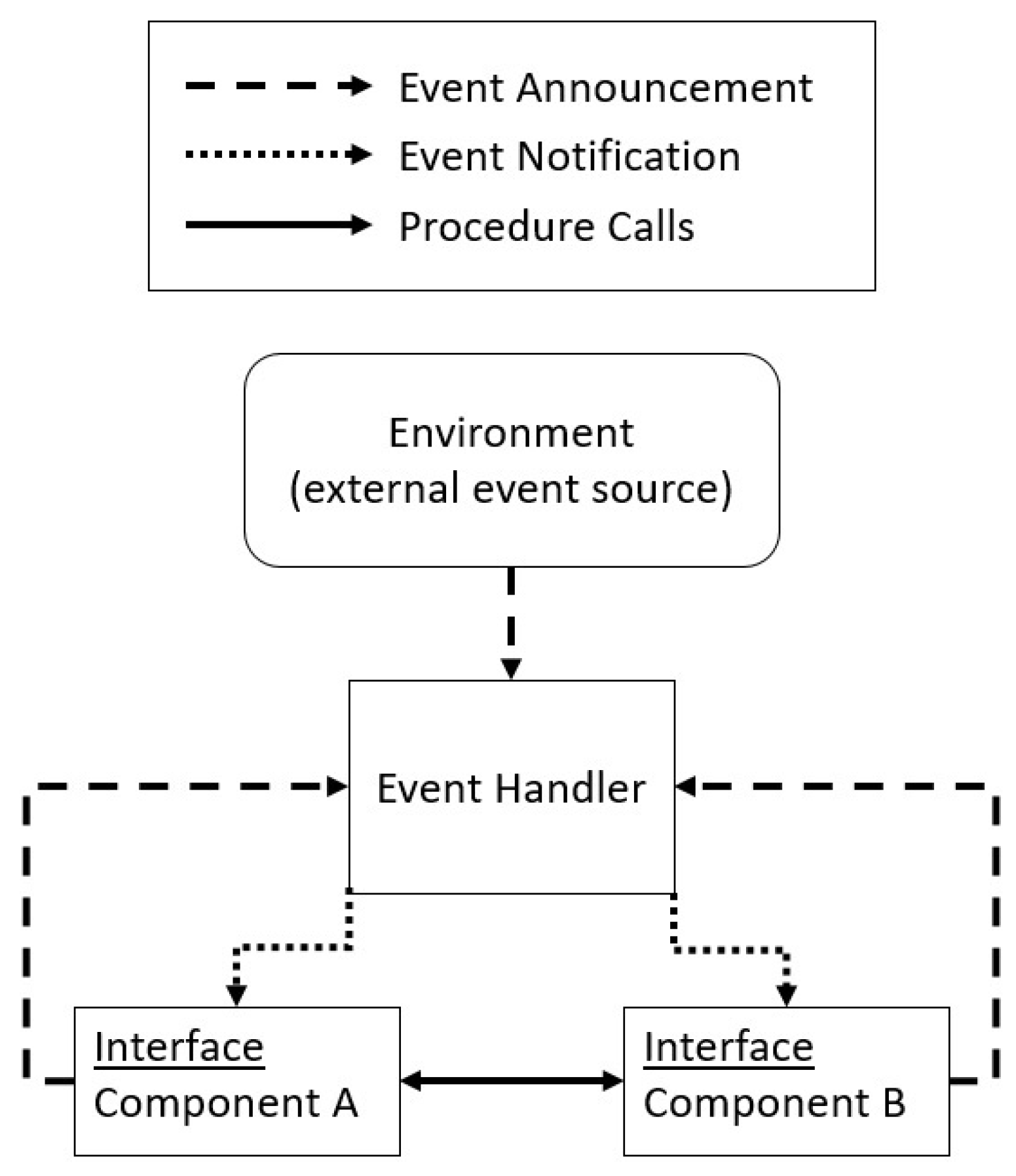
3.1. Implicit Invocation Architectural Pattern
3.2. Identifying the Context
- (C1)
- The application is constructed according to the Implicit Invocation architectural pattern, assuming nondeterministic but fair handling of events.
- As suggested by the Clear Target Audience [16] and Consistent-“Who” [22] patterns, we focus our attention on developers who are working within a software architecture described by the Implicit Invocation pattern. We do not assume any particular programming language or user interface platform in the general description.
- As suggested by the Terminology Tailored to Audience and Understood Notations patterns [16], we use terminology, concepts, and notations that should be familiar to the identified target audience. We also relate the terminology we use in the pattern description to that we use in the Implicit Invocation architectural pattern description.
- As suggested by the Dead Weasels pattern [22], we seek to identify any “weasel words”—words that “imply meaning but have no real substance” or are too ambiguous or imprecise to guide the reader in applying the pattern effectively. We try to replace a “weasel word with a phrase or paragraph that is more specific”. For example, we use a word such as “system” with care because it might have many different meanings in the discussion.
4. Examining Existing Solutions
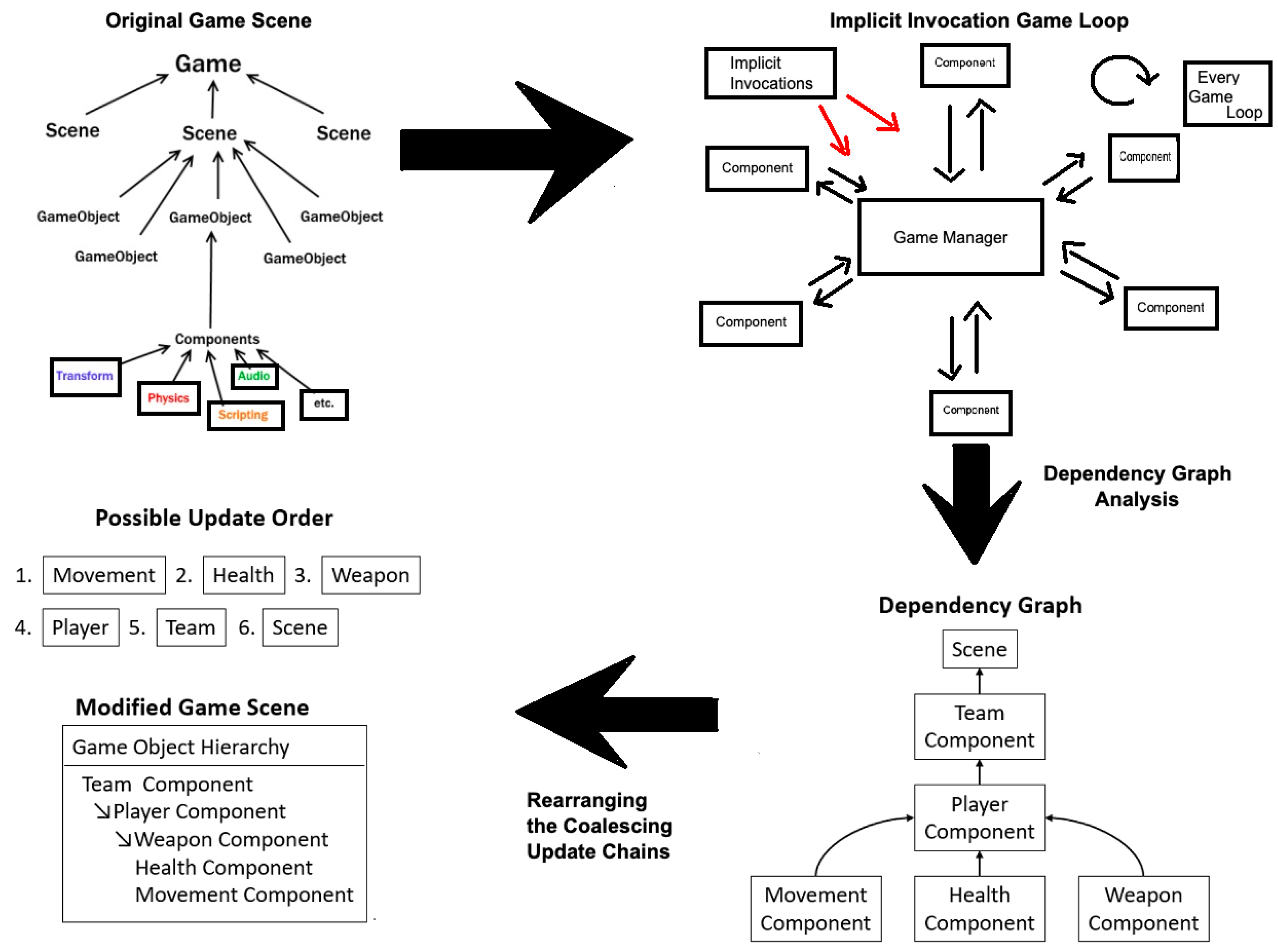
This summary will form a prominent part of the full description of the new pattern’s Solution element.A solution encodes the complex relationships among the application’s components in a dependency graph, and then uses the graph to order the updates of the components without violating the dependency constraints. The goal is to reorder the updates of the components so that the new order reduces transitional turbulence without degrading the performance of the system.
5. Describing the Problem
We want to eliminate or reduce the length of the periods of transitional turbulence during which the external presentation does not accurately reflect the state of the application. We need to do this without sacrificing performance. The goal is to better satisfy the observers’ expectations by increasing the accuracy of the external presentation.
6. Considering the Consequences
6.1. Benefits
- A solution coalesces sets of dependent internal events into “large-grained” events such that the handling of a large-grained event causes the same overall state change as the corresponding set. This can decrease latency and increase accuracy.
- A solution dynamically adapts to changes in an application’s component architecture at run time.
- An application can be readily adapted to use the mechanisms that implement the solution.
6.2. Liabilities
- Changes to an application’s component architecture at run time can increase latency and decrease accuracy.
- Implementing a solution often causes additional processing overhead at startup and shutdown of the application.
- Implementing a solution often causes additional run-time processing overhead, especially when the component architecture changes.
- An application must be adapted to use the mechanisms that implement the solution. Modifying the application often complicates its design, implementation, testing, or use.
7. Identifying the Forces
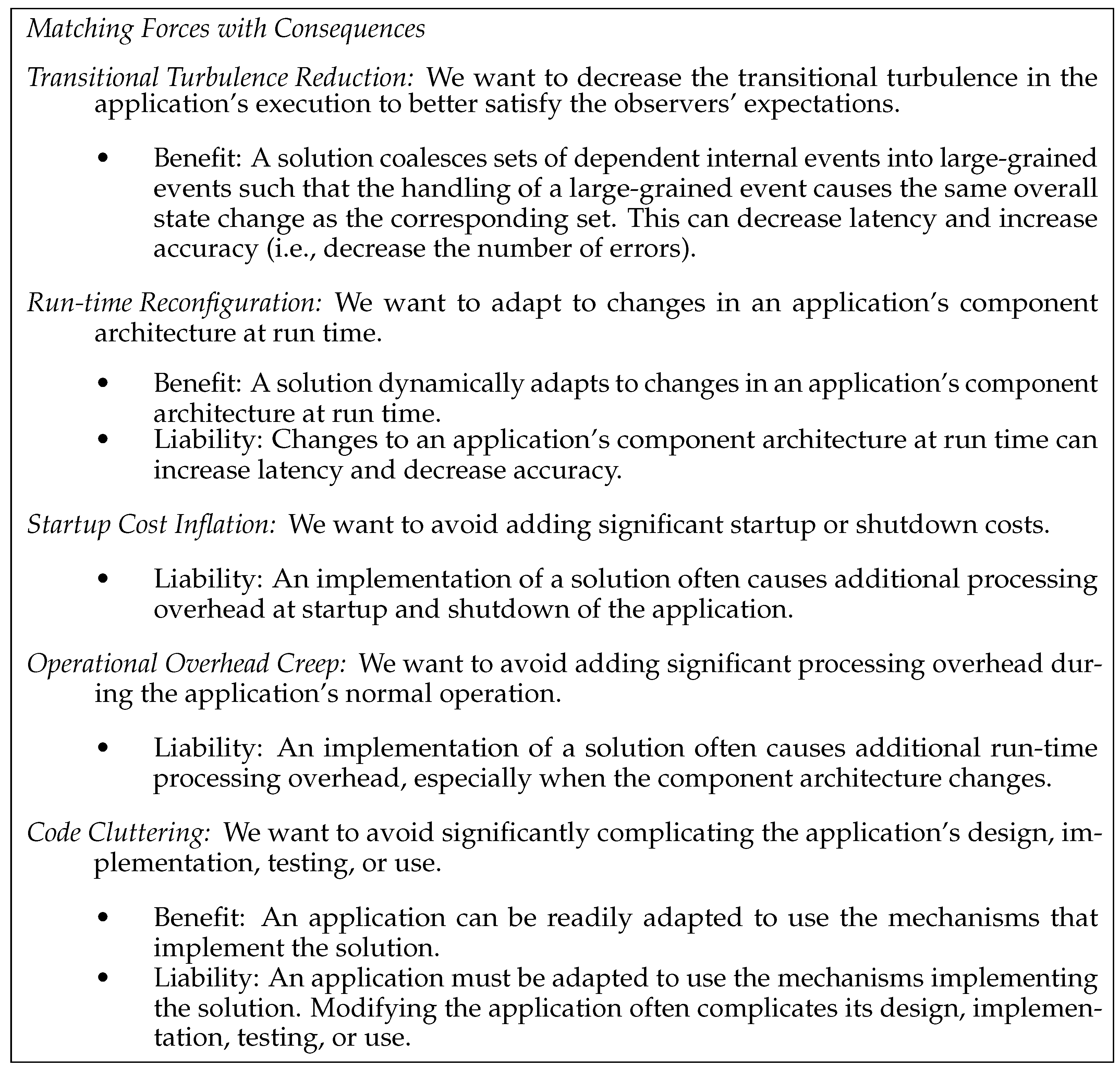
- Transitional Turbulence Reduction: We want to decrease the transitional turbulence in the application’s execution to better satisfy the observers’ expectations.
- Run-time Reconfiguration: We want to adapt to changes in an application’s component architecture at run time.
- Startup Cost Inflation: We want to avoid adding significant startup or shutdown costs.
- If the analysis and modification can be performed statically, then they can be conducted in a preprocessing phase and will thus have a limited impact on the startup and shutdown of the GUI’s execution.
- If the analysis and modification must be performed dynamically, then they must be conducted at run time and can thus have a more significant impact on the startup and shutdown of the GUI’s execution. We want these costs to be small.
- Operational Overhead Creep: We want to avoid adding significant processing overhead during the application’s normal operation.
- Code Cluttering: We want to avoid significantly complicating the application’s design, implementation, testing, or use.
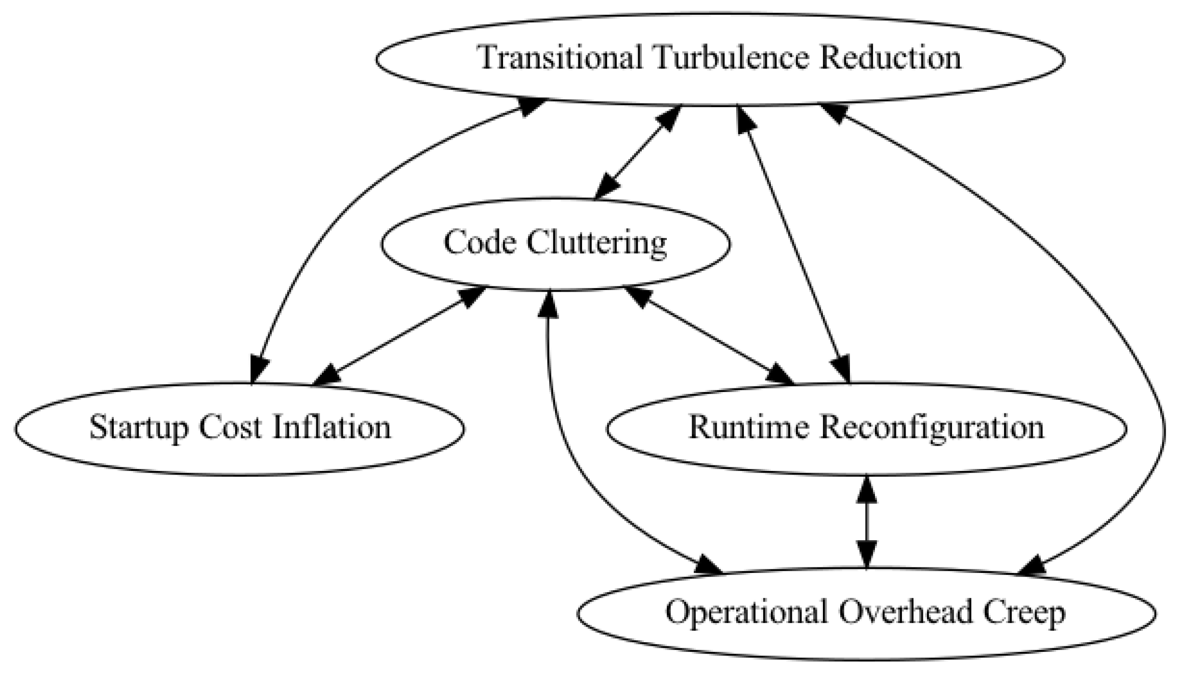
- The Transitional Turbulence Reduction force is in conflict with all the other forces. Seeking to reduce transitional turbulence tends to increase the costs due to the other forces. Seeking to keep the costs due to the other forces low tends to make it difficult to reduce transitional turbulence.
- The Code Cluttering force is in conflict with all the other forces. They represent factors that can make the design and implementation of the code more complex. If no code can be added (i.e., the program is kept uncluttered), then the other forces cannot be satisfied.
- The Run-Time Reconfiguration force is in conflict with Operational Overhead Creep. Dynamically adapting to changes in the application’s component architecture increases the operational overhead cost. If no increase in overhead cost is allowed, then the Run-time Reconfiguration force likely cannot be satisfied.
8. Matching Forces with Consequences
- Each force must be resolved; thus the force must be matched with at least one consequence.
- Each consequence must be matched with exactly one force. That is, it must be the unique result of the resolution of some force.
- A force may match both a benefit and a liability. A solution must seek to realize the benefit without incurring the liability. In Figure 3 note that the Code Cluttering and Run-time Reconfiguration forces each match with both a benefit and a liability.
9. Elaborating the Context
- (C1)
- The application is constructed according to the Implicit Invocation architectural pattern, assuming nondeterministic but fair handling of events.
- (C2)
- The application’s component architecture may change at run time. The application organizes the components into a hierarchical structure. This structure may change dynamically at run time as a result of external stimuli or the actions of components.
- (C3)
- The application presents some aspects of its state that can be observed periodically from outside the system. The timing of this presentation is not under the control of the application.
- (C4)
- Because of the asynchronous nature of the application’s operation, the externally observable presentation may exhibit periods of transitional turbulence.
- (C5)
- Each component is an information-hiding module with a well-defined interface. The only way to change or access its state explicitly is by calling one of its accessor or mutator procedures (e.g., properties in some object-oriented languages).
- (C6)
- The application supports reflection capabilities. That is, application-level code can examine the application’s features (such as its components, events, event handlers, and hierarchical structure) at run time and extract metadata (such as names, types, and the type signatures of the procedures in component interfaces).
10. Choosing the Pattern Name
- The Evocative Name pattern suggests choosing a name that evokes an image that conveys “the essence of the pattern solution to the target audience” [16]. The name should be memorable and suitable for adding to the technical vocabulary of software developers.
- The Noun Phrase Name pattern suggests naming the pattern for the result it creates.
- The Meaningful Metaphor Name pattern further suggests choosing a name based on a metaphor that is familiar to the target audience.
- Dynamically Coalescing Reactive Chains
11. Rewriting the Pattern Elements
11.1. Solution-Writing Guidelines
- The Matching Problem to Solution pattern [21] suggests that the Solution should solve the “whole” Problem “but not more”.
- The Convincing Solution pattern [21] suggests that pattern writers seek to make the Solution “compelling”. Often, this means making it “narrower and deeper”.
- As discussed in Section 4, the “What”-Solutions pattern [22] suggests writing the core idea of the Solution in a one- or two-sentence summary placed at the beginning of the Solution description. The “How”-Process pattern [22] suggests extending the summary with more detail about “what to do, how to do it, and why to do it that way,” including providing any appropriate illustrations. In particular, it should describe how the Solution balances the Forces and identify any Forces that are not considered.
- The Forces Hint at Solution pattern [22] suggests that the Forces should guide the reader from the Problem to the Solution.
11.2. Solution: Summary (from Section 4)
11.3. Solution: Definitions
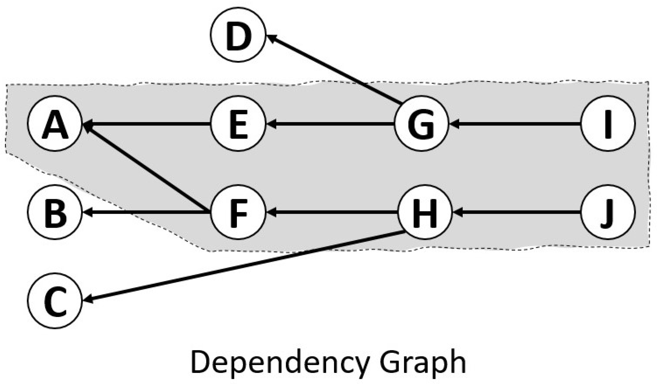
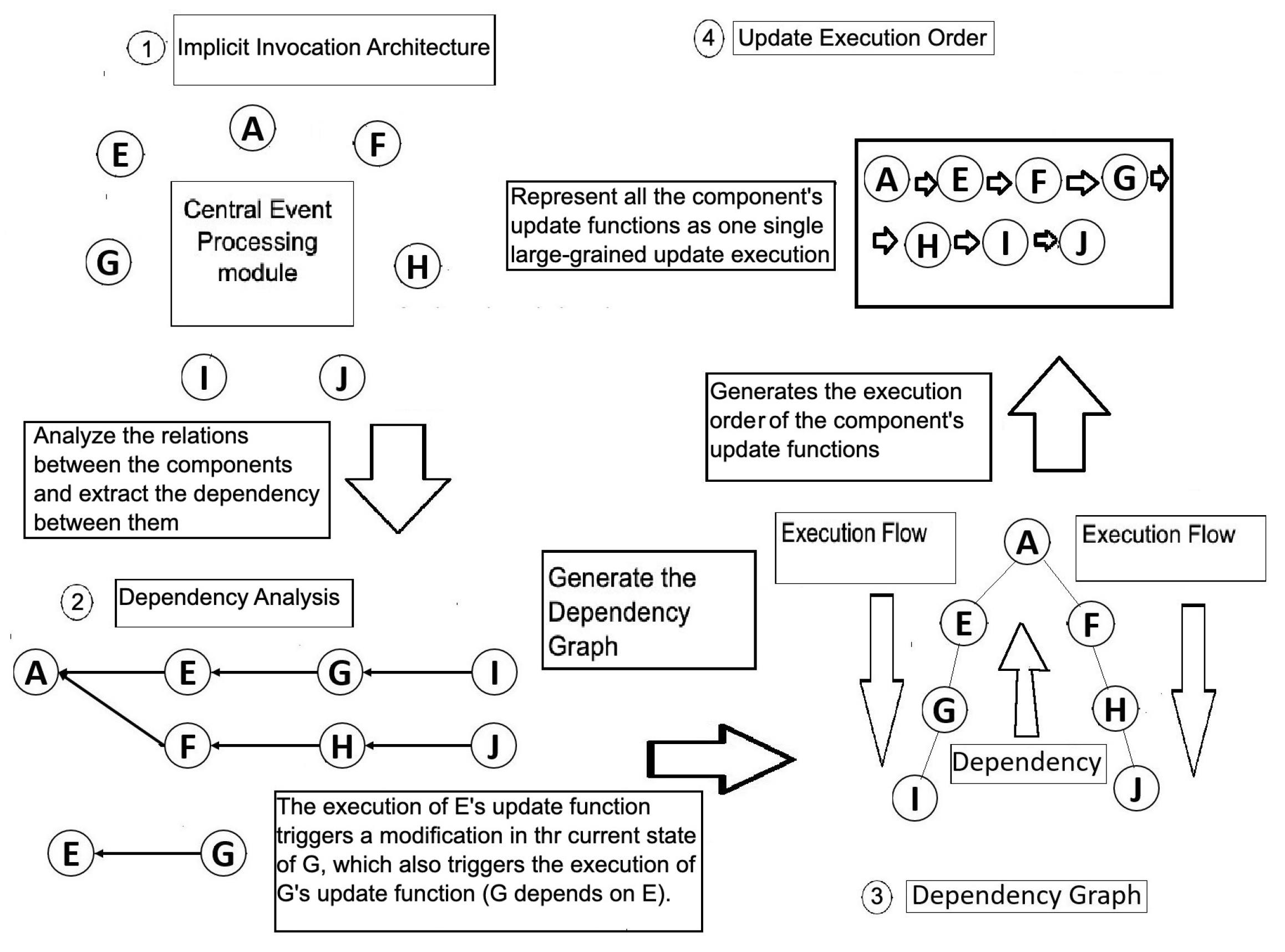
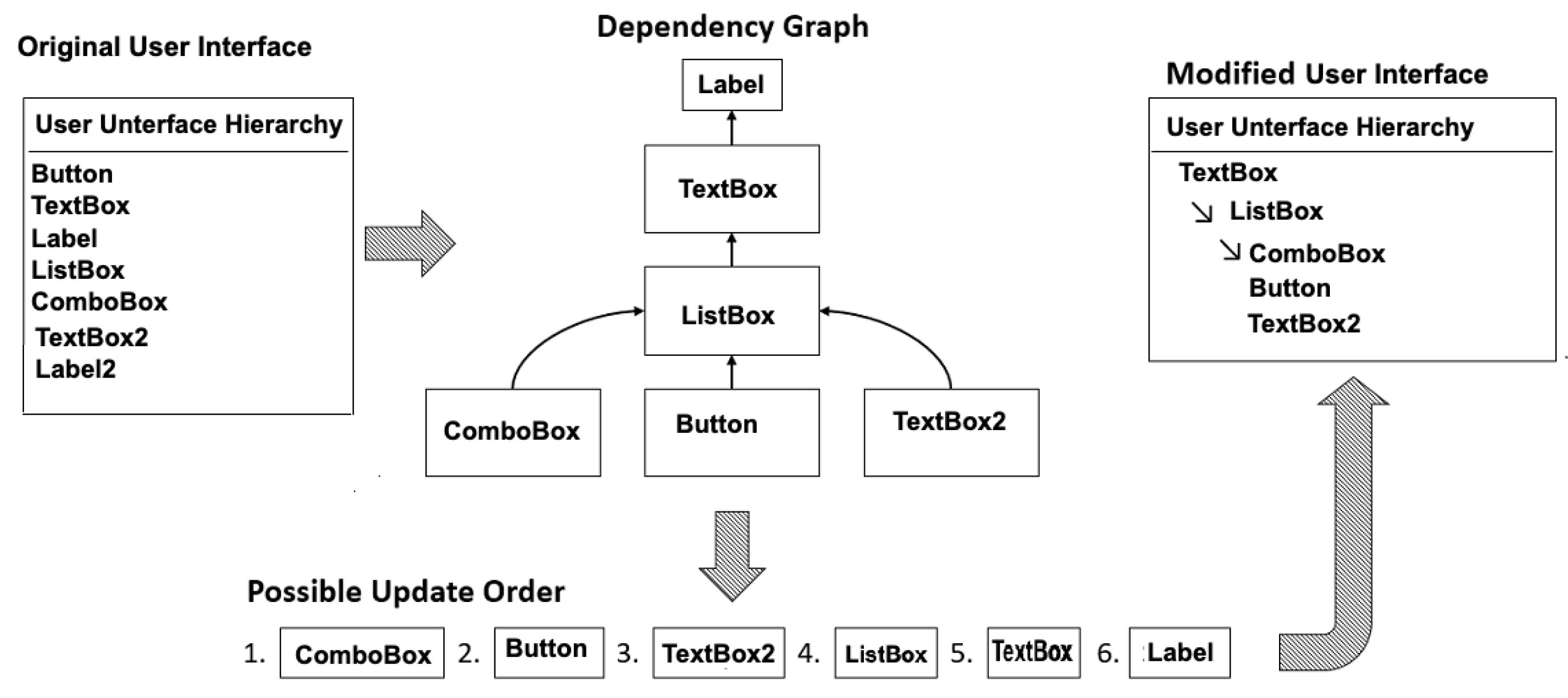
- If the execution of some component X of an application can directly affect a subsequent execution of some other component Y in any way, then Y depends on X. For example, X might trigger an event for which Y listens; change the value of some attribute of its state that Y accesses; directly call one of Y’s mutator procedures; or create, delete, or modify Y.
- A dependency graph is a directed acyclic graph formed by placing the components at the nodes and adding a directed edge from some component Y to some component X only if Y depends on X.
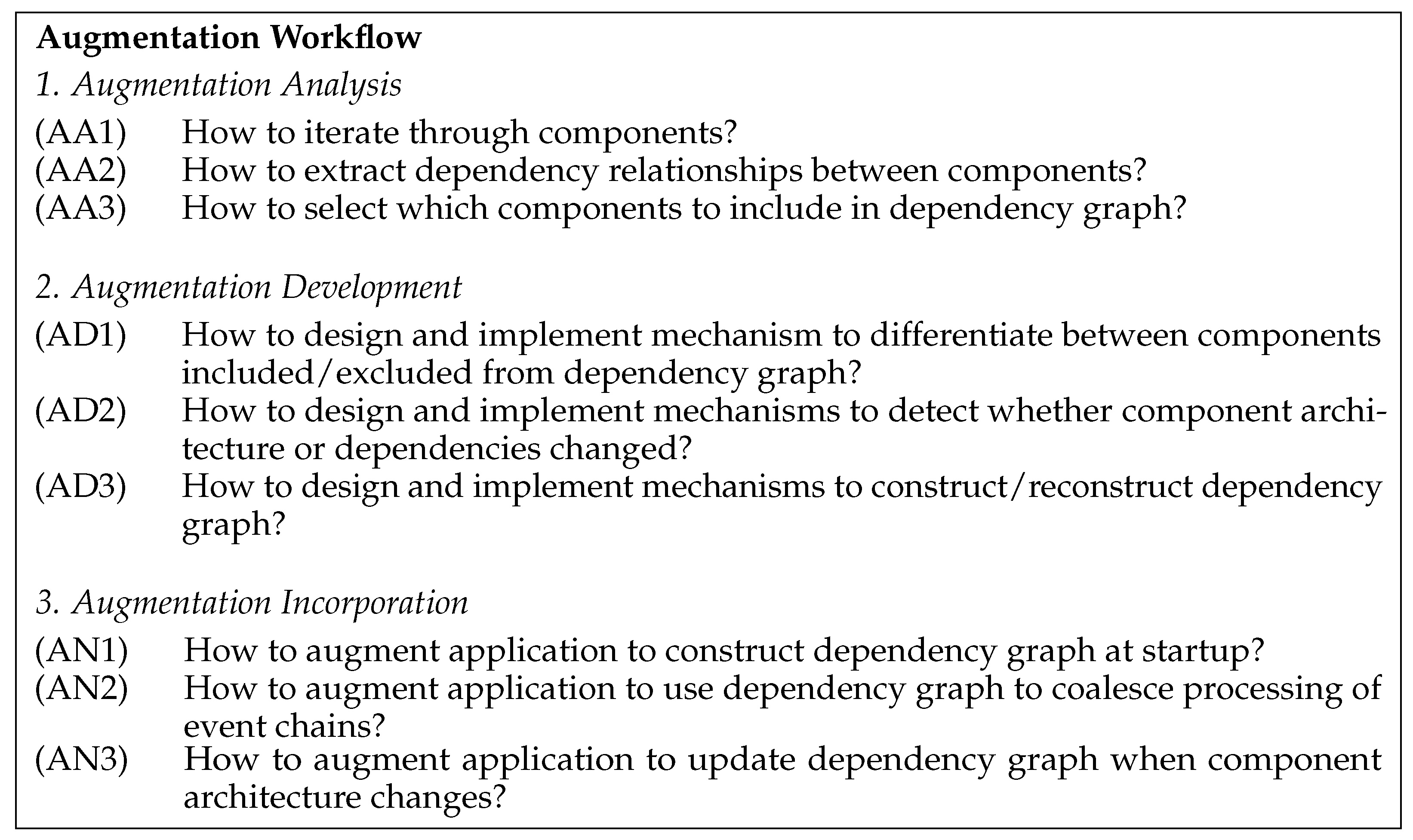
11.4. Solution: Augmenting the Application
- Augmentation analysis, which requires analyzing the application to identify how to add the necessary mechanisms;
- Augmentation development, which requires developing (i.e., designing and implementing) the mechanisms;
- Augmentation incorporation, which requires incorporating the mechanisms into the operation of the application.
11.4.1. Solution: Augmentation Analysis
- (AA1)
- Examine the hierarchical structure to identify how a program can iterate through the components (i.e., accessing each component exactly once).
- (AA2)
- Examine the design and implementation of the components and the features of the implementation language to identify how a program can extract the dependency relationships between the components at run time.
- (AA3)
- Examine the components and events to determine which of the relationships between the components to include in the dependency graph and which to exclude. To reduce transitional turbulence, the augmented application program can manipulate the components and relationships included, but cannot manipulate those excluded.
11.4.2. Solution: Augmentation Development
- (AD1)
- Design and implement a lightweight run-time mechanism that enables the program to differentiate between the components that are to be included in the dependency graph and those that are not.
- (AD2)
- Design and implement a lightweight run-time mechanism that enables the program to detect whether the component architecture or the dependencies among the components have changed since the previous check (or since the beginning of operation).
- (AD3)
- Design and implement lightweight mechanisms to construct the dependency graph initially and to reconstruct it when needed.
11.4.3. Solution: Augmentation Incorporation
- (AN1)
- The application must construct the dependency graph at or before startup.
- (AN2)
- When some component C included in the dependency graph signals an event E, the application must intercept E and directly call the procedures associated with event E on all listening components as recorded in the dependency graph. Then it must recursively apply the process to all events signaled by the listening components. This continues as long as there are dependencies indicated in the graph (which cannot have cycles). This process dynamically coalesces the processing of chains of events into what is processed as one “large-grained” event. The meaning of “intercept” depends on the specific application’s implementation technologies.
- (AN3)
- After processing each “large-grained” event in the previous step, the application must check whether the application’s component architecture has changed (e.g., the addition, modification, or deletion of any component in the hierarchical structure) or the dependencies among components have changed. If so, then the dependency graph must be updated appropriately to reflect the new component architecture.
11.4.4. Solution: Balancing the Forces
Transitional Turbulence Reduction
Run-Time Reconfiguration
Startup Cost Inflation
Operational Overhead Creep
Code Cluttering
12. Putting the Elements in Standard Order
13. Applying the Pattern
Thus, to apply the DCRC pattern, we must show that the beginning application satisfies its Context and Problem, then we modify the application as described by its Solution.To solve an instance of the Problem in the Context apply the Solution.
13.1. Satisfying the Context and Problem
- (C1)
- The application is constructed according to the Implicit Invocation architectural pattern, assuming nondeterministic but fair handling of events.
- (C2)
- The application’s component architecture may change at run time. The application organizes the components into a hierarchical structure. This structure may change dynamically at run time as a result of external stimuli or the actions of components.
- (C3)
- The application presents some aspects of its state that can be observed periodically from outside the system. The timing of this presentation is not under the control of the application.
- (C4)
- Because of the asynchronous nature of the application’s operation, the externally observable presentation may exhibit periods of transitional turbulence.
- (C5)
- Each component is an information-hiding module with a well-defined interface. The only way to change or access its state explicitly is by calling one of its accessor or mutator procedures (e.g., properties in some object-oriented languages).
- (C6)
- The application supports reflection capabilities. That is, application-level code can examine the application’s features (such as its components, events, event handlers, and hierarchical structure) at run time and extract metadata (such as names, types, and the type signatures of the procedures in component interfaces).
We want to eliminate or reduce the length of the periods of transitional turbulence during which the external presentation does not accurately reflect the state of the application. We need to do this without sacrificing performance. The goal is to better satisfy observers’ expectations by increasing the accuracy of the external presentation.
13.2. Constructing a Solution
A solution encodes the complex relationships among the application’s components in a dependency graph and then uses the graph to order the updates of the components without violating the dependency constraints. The goal is to reorder the updates of the components so that the new order reduces transitional turbulence without degrading the performance of the system.
- augmentation analysis, which requires analyzing the application to identify how to add the necessary mechanisms
- augmentation development, which requires developing (i.e., designing and implementing) the mechanisms
- augmentation incorporation, which requires incorporating the mechanisms into the operation of the application
13.2.1. Augmentation Analysis
- (AA1)
- How can we enable a C#/.NET GUI application to iterate through its components?
- (AA2)
- How can we enable a C#/.NET GUI application to extract the dependency relationships between its components?
- (AA3)
- How can we enable a C#/.NET GUI application to select which components to include in and exclude from its dependency graph?
13.2.2. Augmentation Development
- (AD1)
- How can we design and implement a mechanism for a C#/.NET GUI application to differentiate between the components to be included in and excluded from the dependency graph?
- (AD2)
- How can we design and implement a mechanism to detect whether a C#/.NET GUI application’s component architecture or the dependencies among the components have changed?
- (AD3)
- How can we design and implement the mechanism to construct the dependency graph initially and to reconstruct it when needed?
13.2.3. Augmentation Incorporation
- (AN1)
- How can we augment the C#/.NET GUI application to construct the dependency graph at or before startup?
- (AN2)
- How can we augment the C#/.NET GUI application to use the dependency graph to coalesce the processing of chains of events into a “large-grained event”?
- (AN3)
- How can we augment the C#/.NET GUI application to update the dependency graph when the component architecture changes during operation?
13.3. Evaluating the Pattern
14. Discussion
14.1. Evolving the Pattern
14.2. Reflecting on the Writer’s Path Methodology
- As we began to write the DCRC pattern, we observed that the Context, Problem, and Solution elements were entangled with each other and with the incidental details of the implementation technologies, the nature of the application domains, the specific program implementations, and the history of their development. In future research, we suggest that steps 1–3 on the writer’s path be refined further to help writers articulate clear, precise Context, Problem, and Solutions descriptions at an appropriate level of abstraction.
- To match the Forces with the Consequences, we found it necessary to refactor both the Forces and the Consequences to ensure that the issues were covered in compatible ways. In future research, we suggest that writer’s path steps 4–6 be enhanced to help pattern writers identify the Forces and Consequences and state them compatibly.
- As stated in Section 11, the DCRC pattern’s Solution element is complex and, thus, difficult to understand. In future research, we suggest that the writer’s path be refined further to guide pattern writers in extracting essential information from existing solutions, narrowing the scope, and simplifying the pattern description.
- As we were rewriting the Solution (in writer’s path Step 9), we found it necessary to revise the Context to capture several subtle assumptions made by the full Solution description (e.g., support for reflection). In future research, we suggest that the earlier steps of the writer’s path be enhanced to help pattern writers identify the Solution’s assumptions about the application’s environment.
- The writer’s path methodology does not currently address how to collect feedback from users and incorporate changes into the pattern, except by repeating the relevant steps. In future research, we suggest extending the methodology to guide pattern writers during this maintenance phase of the pattern life cycle, in particular, on when and how to evolve a pattern into a pattern language [46,47,48].
14.3. Leveraging Related Research
15. Conclusions
Author Contributions
Funding
Data Availability Statement
Acknowledgments
Conflicts of Interest
Abbreviations
| AR | Augmented Reality |
| DCRC | Dynamically Coalescing Reactive Chains design pattern |
| GUI | Graphical User Interface |
| II | Implicit Invocation architectural pattern |
| MVC | Model-View-Controller design pattern |
| VR | Virtual Reality |
Appendix A. Examining Two Existing Solutions
- Dynamic virtual reality (VR) and augmented reality (AR) applications implemented in the Unity3D game engine using C# [5].
Appendix A.1. Dynamic GUI Application

Appendix A.2. Dynamic VR Applications

Appendix B. Final Design Pattern
Appendix B.1. Pattern Name
Appendix B.2. Context
- (C1)
- The application is constructed according to the Implicit Invocation architectural pattern, assuming nondeterministic but fair handling of events.
- (C2)
- The application’s component architecture may change at run time. The application organizes the components into a hierarchical structure. This structure may change dynamically at run time as a result of external stimuli or the actions of components.
- (C3)
- The application presents some aspects of its state that can be observed periodically from outside the system. The timing of this presentation is not under the control of the application.
- (C4)
- Because of the asynchronous nature of the application’s operation, the externally observable presentation may exhibit periods of transitional turbulence.
- (C5)
- Each component is an information-hiding module with a well-defined interface. The only way to change or access its state explicitly is by calling one of its accessor or mutator procedures (e.g., properties in some object-oriented languages).
- (C6)
- The application supports reflection capabilities. That is, application-level code can examine the application’s features (such as its components, events, event handlers, and hierarchical structure) at run time and extract metadata (such as names, types, and the type signatures of the procedures in component interfaces).
Appendix B.3. Problem
Appendix B.4. Forces
- Transitional Turbulence Reduction:
- We want to decrease the transitional turbulence in the application’s execution to better satisfy the observers’ expectations.
- Run-time Reconfiguration:
- We want to adapt to changes in an application’s component architecture at run time.
- Startup Cost Inflation:
- We want to avoid adding significant startup or shutdown costs.
- Operational Overhead Creep:
- We want to avoid adding significant processing overhead during the application’s normal operation.
- Code Cluttering:
- We want to avoid significantly complicating the application’s design, implementation, testing, or use.
Appendix B.5. Solution
Appendix B.5.1. Solution: Summary
Appendix B.5.2. Solution: Definitions
- If the execution of some component X of an application can directly affect a subsequent execution of some other component Y in any way, then Y depends on X. For example, X might trigger an event for which Y listens; change the value of some attribute of its state that Y accesses; directly call one of Y’s mutator procedures; or create, delete, or modify Y.
- A dependency graph is a directed acyclic graph formed by placing the components at the nodes and adding a directed edge from some component Y to some component X only if Y depends on X.
Appendix B.5.3. Solution: Augmenting the Application
- Augmentation analysis, which requires analyzing the application to identify how to add the necessary mechanisms;
- Augmentation development, which requires developing (i.e., designing and implementing) the mechanisms;
- Augmentation incorporation, which requires incorporating the mechanisms into the operation of the application.
Solution: Augmentation Analysis
- (AA1)
- Examine the hierarchical structure to identify how a program can iterate through the components (i.e., accessing each component exactly once).
- (AA2)
- Examine the design and implementation of the components and the features of the implementation language to identify how a program can extract the dependency relationships between the components at run time.
- (AA3)
- Examine the components and events to determine which of the relationships between the components to include in the dependency graph and which to exclude. To reduce transitional turbulence, the augmented application program can manipulate the components and relationships included, but cannot manipulate those excluded.
Solution: Augmentation Development
- (AD1)
- Design and implement a lightweight run-time mechanism that enables the program to differentiate between the components that are to be included in the dependency graph and those that are not.
- (AD2)
- Design and implement a lightweight run-time mechanism that enables the program to detect whether the component architecture or the dependencies among the components have changed since the previous check (or since the beginning of operation).
- (AD3)
- Design and implement lightweight mechanisms to construct the dependency graph initially and to reconstruct it when needed.
Solution: Augmentation Incorporation
- (AN1)
- The application must construct the dependency graph at or before startup.
- (AN2)
- When some component C included in the dependency graph signals an event E, the application must intercept E and directly call the procedures associated with event E on all listening components as recorded in the dependency graph. Then it must recursively apply the process to all events signalled by the listening components. This continues as long as there are dependencies indicated in the graph (which cannot have cycles). This process dynamically coalesces the processing of chains of events into what is processed as one “large-grained” event. The meaning of “intercept” depends on the specific application’s implementation technologies.
- (AN3)
- After processing each “large-grained” event in the previous step, the application must check whether the application’s component architecture has changed (e.g., the addition, modification, or deletion of any component in the hierarchical structure) or the dependencies among components have changed. If so, then the dependency graph must be updated appropriately to reflect the new component architecture.
Appendix B.5.4. Solution: Balancing the Forces
Transitional Turbulence Reduction
Run-Time Reconfiguration
Startup Cost Inflation
Operational Overhead Creep
Code Cluttering
Appendix B.6. Consequences
Appendix B.6.1. Benefits
- Transitional Turbulence Reduction: A solution coalesces sets of dependent internal events into “large-grained” events such that the handling of a large-grained event causes the same overall state change as the corresponding set. This can decrease latency and increase accuracy (i.e., decrease the number of errors).
- Run-time Configuration: A solution dynamically adapts to changes in an application’s component architecture at run time.
- Code Cluttering: An application can be readily adapted to use the mechanisms that implement the solution.
Appendix B.6.2. Liabilities
- Run-time Reconfiguration: Changes to an application’s component architecture at run time can increase latency and decrease accuracy.
- Startup Cost Inflation: Implementing a solution often causes additional processing overhead at startup and shutdown of the application.
- Operational Overhead Creep: Implementing a solution often causes additional run-time processing overhead, especially when the component architecture changes.
- Code Cluttering: An application must be adapted to use the mechanisms that implement the solution. Modifying the application often complicates its design, implementation, testing, or use.
References
- Chandy, M.K.; Misra, J. Parallel Program Design: A Foundation; Addison Wesley: Boston, MA, USA, 1988. [Google Scholar]
- Lorenz, E.N. Deterministic Nonperiodic Flow. J. Atmos. Sci. 1963, 20, 130–141. [Google Scholar] [CrossRef]
- Cooper, G.H.; Krishnamurthi, S. Embedding Dynamic Dataflow in a Call-by-Value Language. In Proceedings of the Programming Languages and Systems, 15th European Symposium on Programming, Vienna, Austria, 27–28 March 2006; pp. 294–308. [Google Scholar]
- Mijač, M.; García-Cabot, A.; Strahonja, V. Reactor Design Pattern. TEM J. Technol. Educ. Inform. 2021, 10, 18–30. [Google Scholar] [CrossRef]
- Marum, J.P.O.; Jones, J.A.; Cunningham, H.C. Dependency Graph-based Reactivity for Virtual Environments. In Proceedings of the IEEE VR 2020 Workshop on Software Engineering and Architectures for Interactive Systems (SEARIS), Atlanta, GA, USA, 22–26 March 2020; pp. 246–253. [Google Scholar]
- Marum, J.P.O.; Cunningham, H.C.; Jones, J.A. Unified Library for Dependency Graph Reactivity on Web and Desktop User Interfaces. In Proceedings of the ACM Southeast Conference, ACMSE 2020, Tampa, FL, USA, 2–4 April 2020; pp. 26–33. [Google Scholar]
- Bainomugisha, E.; Carreton, A.L.; van Cutsem, T.; Mostinckx, S.; de Meuter, W. A Survey on Reactive Programming. ACM Comput. Surv. 2013, 45, 1–34. [Google Scholar] [CrossRef]
- Marum, J.P.O.; Cunningham, H.C.; Jones, J.A. Unified Library for Dependency Graph Reactivity on Web and Desktop User Interfaces: ADDENDUM; Technical Report; University of Mississippi, Department of Computer and Information Science: Oxford, MS, USA, 2020; Available online: https://john.cs.olemiss.edu/~hcc/papers/Addendum_ACMSE_2020.pdf (accessed on 16 January 2024).
- Blackheath, S.; Jones, A. Functional Reactive Programming; Manning: Shelter Island, NY, USA, 2016. [Google Scholar]
- ReactiveX Project. ReactiveX: An API for Asynchronous Programming with Observable Streams. 2023. Available online: http://reactivex.io (accessed on 16 January 2024).
- Unity Technologies. Unity User Manual 2020.3; Unity Technologies: San Francisko, CA, USA, 2023; Available online: https://docs.unity3d.com/Manual (accessed on 16 January 2024).
- Kawai, Y. UniRx: Reactive Extensions for Unity3D. GitHub. 2024. Available online: https://github.com/neuecc/UniRx (accessed on 16 January 2024).
- Buschmann, F.; Meunier, R.; Rohnert, H.; Sommerlad, P.; Stal, M. Pattern-Oriented Software Architecture: A System of Patterns; Wiley: Chichester, UK, 1996; Volume 1. [Google Scholar]
- Gamma, E.; Helm, R.; Johnson, R.; Vlissides, J. Design Patterns: Elements of Reusable Object-Oriented Software; Addison Wesley: Boston, MA, USA, 1995. [Google Scholar]
- Wellhausen, T.; Fiesser, A. How to Write a Pattern? A Rough Guide for First-Time Pattern Authors. In Proceedings of the 16th European Conference on Pattern Languages of Programs, EuroPLOP ’11, Irsee, Germany, 11–15 July 2011; pp. 1–9. [Google Scholar]
- Meszaros, G.; Doble, J. A Pattern Language for Pattern Writing. In Pattern Languages of Program Design 3; Addison Wesley: Boston, MA, USA, 1998; pp. 529–574. [Google Scholar]
- Garlan, D.; Shaw, M. An Introduction to Software Architecture. In Advances in Software Engineering and Knowledge Engineering; Ambriola, V., Tortora, G., Eds.; World Scientific: Singapore, 1993; pp. 1–39. [Google Scholar]
- Qian, K.; Fu, X.; Tao, L.; Xu, C.W.; Diaz-Herrera, J.L. Software Architecture and Design Illuminated; Jones & Bartlett Learning: Burlington, MA, USA, 2010. [Google Scholar]
- Iba, T. How to Write Patterns: A Practical Guide for Creating a Pattern Language on Human Actions. 2021 Pattern Languages of Programs Conference, PloPourri, a Methodological, Philosophical, and Educational Study on Pattern Languages. 2022. Available online: https://hillside.net/plop/2021/plopourri/PLoP21_PLOPOURRI_Iba_Methodology4.pdf (accessed on 16 January 2024).
- Coplien, J.; Hoffman, D.; Weiss, D. Commonality and Variability in Software Engineering. IEEE Softw. 1998, 15, 37–45. [Google Scholar] [CrossRef]
- Harrison, N.B. The Language of Shepherding: A Pattern Language for Shepherds and Sheep. In Pattern Languages of Program Design; Harrison, N., Foote, B., Rohnert, H., Eds.; Addison Wesley: Boston, MA, USA, 1999; Volume 4, pp. 507–530. [Google Scholar]
- Harrison, N.B. Advanced Pattern Writing: Patterns for Experienced Writers. In Pattern Languages of Program Design; Manolescu, D.A., Voelter, M., Noble, J., Eds.; Chapter 16; Addison Wesley: Boston, MA, USA, 2006; Volume 5, pp. 433–451. [Google Scholar]
- Garlan, D.; Notkin, D. Formalizing Design Spaces: Implicit Invocation Mechanisms. In Proceedings of the VDM’91, Formal Software Development Methods: Proceedings of the International Symposium of VDM Europe, Noordwijkerhout, The Netherlands, 21–25 October 1991; pp. 31–44. [Google Scholar]
- Shaw, M. Some Patterns for Software Architectures. In Pattern Languages of Program Design; Vlissides, J., Coplien, J.O., Kerth, N.L., Eds.; Addison Wesley: Boston, MA, USA, 1996; Volume 2, pp. 255–269. [Google Scholar]
- Qian, K.; Fu, X.; Tao, L.; Xu, C.; Diaz-Herrera, J.L. Implicit Asynchronous Communication Software Architecture. In Software Architecture and Design Illuminated; Chapter 8; Jones & Bartlett Learning: Burlington, MA, USA, 2010; pp. 177–198. [Google Scholar]
- Shaw, M.; DeLine, R.; Klein, D.V.; Ross, T.L.; Young, D.M.; Zelesnik, G. Abstractions for Software Architecture and Tools to Support Them. IEEE Trans. Softw. Eng. 1995, 21, 314–335. [Google Scholar] [CrossRef]
- Garlan, D. Software Architecture. In Wiley Encyclopedia of Computer and Science Engineering; Wah, B.W., Ed.; Wiley Online Library: Hoboken, NJ, USA, 2007. [Google Scholar]
- Eugster, P.T.; Felber, P.A.; Guerraoui, R.; Kermarrec, A. The Many Faces of Publish/Subscribe. ACM Comput. Surv. 2003, 35, 114–131. [Google Scholar] [CrossRef]
- Mijač, M.; Kermek, D.; Zlatko, S. Complex Propagation of Events: Design Patterns Comparison. In Information Systems Development: Transforming Organisations and Society (ISD2014 Proceedings); Strahonja, V., Vrček, N., Plantak Vukovac, D., Barry, C., Lang, M., Linger, H., Schneider, C., Eds.; University of Zagreb, Faculty of Organization and Informatics: Varaždin, Croatia, 2014; pp. 306–316. [Google Scholar]
- Czaplicki, E.; Chong, S. Asynchronous Functional Reactive Programming for GUIs. In Proceedings of the 34th SIGPLAN Conference on Programming Language Design and Implementation, PLDI ’13, Seattle, WA, USA, 16–19 June 2013; pp. 411–422. [Google Scholar]
- Drechsler, J.; Salvaneschid, G.; Mogk, R.; Mezini, M. Distributed REScala: An Update Algorithm for Distributed Reactive Programming. In Proceedings of the 2014 ACM International Conference on Object Oriented Programming Systems Languages and Applications, OOPSLA 2014, Portland, OR, USA, 20–24 October 2014; pp. 361–376. [Google Scholar]
- Elliott, C.M. Push-Pull Functional Reactive Programming. In Proceedings of the 2nd SIGPLAN Symposium on Haskell, Haskell ’09, Edinburgh, UK, 3 September 2009; pp. 25–36. [Google Scholar]
- Meyerovich, L.A.; Guha, A.; Baskin, J.; Cooper, G.H.; Greenberg, M.; Bromfield, A.; Krishnamurthi, S. Flapjax: A Programming Language for Ajax Applications. In Proceedings of the 24th ACM SIGPLAN Conference on Object Oriented Programming Systems Languages and Applications, OOPSLA 2009, Orlando, FL, USA, 25–29 October 2009; pp. 1–20. [Google Scholar]
- Reynders, B.; Devriese, D.; Piessens, F. Experience Report: Functional Reactive Programming and the DOM. In Proceedings of the Companion to the First International Conference on the Art, Science and Engineering of Programming, Programming ’17, Brussels, Belgium, 3–6 April 2017; pp. 23:1–23:6. [Google Scholar]
- Mijač, M.; Garcia-Cabot, A.; Strahonja, V. REFRAME—A Software Framework for Managing Reactive Dependencies in Object-oriented Applications. SoftwareX 2023, 24, 101571. [Google Scholar] [CrossRef]
- Parnas, D.L. On the Criteria to Be Used in Decomposing Systems into Modules. Commun. ACM 1972, 15, 1053–1058. [Google Scholar] [CrossRef]
- Britton, K.H.; Parker, R.A.; Parnas, D.L. A Procedure for Designing Abstract Interfaces for Device Interface Modules. In Proceedings of the 5th International Conference on Software Engineering, San Diego, CA, USA, 9–12 March 1981; pp. 195–204. [Google Scholar]
- Parnas, D.L. The Secret History of Information Hiding. In Software Pioneers: Contributions to Software Engineering; Broy, M., Denert, E., Eds.; Springer: Berlin/Heidelberg, Germany, 2002; pp. 398–409. [Google Scholar]
- Mijač, M. Evaluation of Design Science Instantiation Artifacts in Software Engineering Research. In Proceedings of the Central European Conference on Information and Intelligent Systems, Varaždin, Croatia, 2–4 October 2019; pp. 313–321. [Google Scholar]
- Engström, E.; Storey, M.; Runeson, P.; Höst, M.; Baldassarre, M.T. How Software Engineering Research Aligns with Design Science: A Review. Empir. Softw. Eng. 2020, 25, 2630–2660. [Google Scholar] [CrossRef]
- Cunningham, H.C.; Zhang, C.; Liu, Y. Keeping Secrets within a Family: Rediscovering Parnas. In Proceedings of the International Conference on Software Engineering Research and Practice (SERP), Las Vegas, NV, USA, 21–24 June 2004; pp. 712–718. [Google Scholar]
- The Hillside Group. A Group Dedicated to Design Patterns. 2023. Available online: https://hillside.net (accessed on 16 January 2024).
- Chin, S.; Vos, J.; Weaver, J. The Definitive Guide to Modern Java Clients with JavaFX; Apress: New York, NY, USA, 2019. [Google Scholar]
- OpenJFX Project. JavaFX. Gluon. 2024. Available online: https://openjfx.io (accessed on 16 January 2024).
- Cleary, A.; Vandenbergh, L.; Peterson, J. Reactive Game Engine Programming for STEM Outreach. In Proceedings of the 46th ACM Technical Symposium on Computer Science Education, SIGCSE ’15, Kansas City, MO, USA, 4–7 March 2015; pp. 628–632. [Google Scholar]
- Buschmann, F.; Henney, K.; Schmidt, D.C. Pattern-Oriented Software Architecture, On Patterns and Pattern Languages; Wiley: Chichester, UK, 2007; Volume 5. [Google Scholar]
- Iba, T.; Isaku, T. A Pattern Language for Creating Pattern Languages: 364 Patterns for Pattern Mining, Writing, and Symbolizing. In Proceedings of the 23rd Conference on Pattern Languages of Programs, PLoP ’16, Monticello, IL, USA, 23 October 2016; pp. 1–63. [Google Scholar]
- Iba, T.; Kanai, T. Systematization of Patterns for Weaving a Pattern Language as a Whole. 2021 Pattern Languages of Programs Conference, PloPourri, a Methodological, Philosophical, and Educational Study on Pattern Languages. 2022. Available online: https://hillside.net/plop/2021/plopourri/PLoP21_PLOPOURRI_Iba_Methodology2.pdf (accessed on 16 January 2024).
- Kohls, C.; Panke, S. Is That True…? Thoughts on the Epistemology of Patterns. In Proceedings of the 16th Conference on Pattern Languages of Programs, PLoP ’09, Chicago, IL, USA, 28–30 August 2009; pp. 1–14. [Google Scholar]
- Riehle, D.; Harutyunyan, N.; Barcomb, A. Pattern Discovery and Validation Using Scientific Research Methods. In Transactions on Pattern Languages of Programming V (TPLoP); Lecture Notes in Computer Science; Springer: Berlin/Heidelberg, Germany, 2021; pp. 1–25. Available online: https://arxiv.org/abs/2107.06065 (accessed on 16 January 2024).
- Eales, A. The Observer Pattern Revisited. In Educating, Innovating & Transforming: Educators in IT: Concise Paper; The Pennsylvania State University: State College, PA, USA, 2005. [Google Scholar]
- Riehle, D. The Event Notification Pattern—Integrating Implicit Invocation with Object-Orientation. Theory Pract. Object Syst. 1996, 2, 43–52. [Google Scholar] [CrossRef][Green Version]
- Feiler, P.H.; Tichy, W.F. Propagator: A Family of Patterns. In Proceedings of the TOOLS USA 97. International Conference on Technology of Object Oriented Systems and Languages, IEEE, Santa Barbara, CA, USA, 1 August 1997; pp. 355–366. [Google Scholar]
- Garlan, D.; Jha, S.; Notkin, D.; Dingel, J. Reasoning about Implicit Invocation. In Proceedings of the 6th ACM SIGSOFT International Symposium on Foundations of Software Engineering, Lake Buena, SIGSOFT ’98/FSE-6, Vista, FL, USA, 3–5 November 1998; pp. 209–221. [Google Scholar]
- Mikkonen, T. Formalizing Design Patterns. In Proceedings of the 20th International Conference on Software Engineering, Kyoto, Japan, 19–25 April 1998; pp. 115–124. [Google Scholar] [CrossRef]
- Garlan, D.; Khersonsky, S. Model Checking Implicit-Invocation Systems. In Proceedings of the Tenth International Workshop on Software Specification and Design, IWSSD, San Diego, CA, USA, 5–7 November 2000; pp. 23–30. [Google Scholar]
- Garlan, D.; Khersonsky, S.; Kim, J.S. Model Checking Publish-Subscribe Systems. In Proceedings of the International SPIN Workshop on Model Checking of Software, Portland, OR, USA, 9–10 May 2003; pp. 166–180. [Google Scholar]
- Xu, J.; Rajan, H.; Sullivan, K. Aspect Reasoning by Reduction to Implicit Invocation. In Proceedings of the Foundations of Aspect-Oriented Languages Workshop (FOAL), Lancaster, UK, 23 March 2004; pp. 31–36. [Google Scholar]
- Soundarajan, N.; Hallstrom, J.O. Responsibilities and Rewards: Specifying Design Patterns. In Proceedings of the 26th International Conference on Software Engineering, IEEE, Edinburgh, UK, 28 May 2004; pp. 666–675. [Google Scholar]
- Soundarajan, N.; Hallstrom, J.O.; Shu, G.; Delibas, A. Patterns: From System Design to Software Testing. Innov. Syst. Softw. Eng. 2008, 4, 71–85. [Google Scholar] [CrossRef]
- Fiadeiro, J.L.; Lopes, A. An Algebraic Semantics of Event-based Architectures. Math. Struct. Comput. Sci. 2007, 17, 1029–1073. [Google Scholar] [CrossRef][Green Version]
- Valero, V.; Macia, H.; Díaz, G.; Cambronero, M.E. Colored Petri Net Modeling of the Publish/Subscribe Paradigm in the Context of Web Services Resources. In Proceedings of the Formal Methods for Industrial Critical Systems: Proceedings of the 20th International Workshop, FMICS 2015, Oslo, Norway, 22–23 June 2015; pp. 81–95. [Google Scholar]
- Marum, J.P.O. Dependency-based Reactive Change Propagation Design Pattern Applied to Environments with High Unpredictability. Ph.D. Thesis, University of Mississippi, Department of Computer and Information Science, University, MS, USA, 2021. Available online: https://egrove.olemiss.edu/etd/2122 (accessed on 16 January 2024).
- Marum, J.P.O.; Jones, J.A.; Cunningham, H.C. Towards a Reactive Game Engine. In Proceedings of the 50th IEEE SouthEastCon, Huntsville, AL, USA, 11–14 April 2019; pp. 1–8. [Google Scholar]


Disclaimer/Publisher’s Note: The statements, opinions and data contained in all publications are solely those of the individual author(s) and contributor(s) and not of MDPI and/or the editor(s). MDPI and/or the editor(s) disclaim responsibility for any injury to people or property resulting from any ideas, methods, instructions or products referred to in the content. |
© 2024 by the authors. Licensee MDPI, Basel, Switzerland. This article is an open access article distributed under the terms and conditions of the Creative Commons Attribution (CC BY) license (https://creativecommons.org/licenses/by/4.0/).
Share and Cite
Oliveira Marum, J.P.; Cunningham, H.C.; Jones, J.A.; Liu, Y. Following the Writer’s Path to the Dynamically Coalescing Reactive Chains Design Pattern. Algorithms 2024, 17, 56. https://doi.org/10.3390/a17020056
Oliveira Marum JP, Cunningham HC, Jones JA, Liu Y. Following the Writer’s Path to the Dynamically Coalescing Reactive Chains Design Pattern. Algorithms. 2024; 17(2):56. https://doi.org/10.3390/a17020056
Chicago/Turabian StyleOliveira Marum, João Paulo, H. Conrad Cunningham, J. Adam Jones, and Yi Liu. 2024. "Following the Writer’s Path to the Dynamically Coalescing Reactive Chains Design Pattern" Algorithms 17, no. 2: 56. https://doi.org/10.3390/a17020056
APA StyleOliveira Marum, J. P., Cunningham, H. C., Jones, J. A., & Liu, Y. (2024). Following the Writer’s Path to the Dynamically Coalescing Reactive Chains Design Pattern. Algorithms, 17(2), 56. https://doi.org/10.3390/a17020056