Abstract
To enforce the conservation of mass principle, a pressure Poisson equation arises in the numerical solution of incompressible fluid flow using the pressure-based segregated algorithms such as projection methods. For unsteady flows, the pressure Poisson equation is solved at each time step usually in physical space using iterative solvers, and the resulting pressure gradient is then applied to make the velocity field divergence-free. It is generally accepted that this pressure-correction stage is the most time-consuming part of the flow solver and any meaningful acceleration would contribute significantly to the overall computational efficiency. The objective of the present work was to develop a fast hybrid pressure-correction algorithm for numerical simulation of incompressible flows around obstacles in the context of projection methods. The key idea is to adopt different numerical methods/discretisations in the sub-steps of projection methods. Here, a classical second-order time-marching projection method, which consists of two sub-steps, was chosen for the purposes of demonstration. In the first sub-step, the momentum equations were discretised on unstructured grids and solved by conventional numerical methods, here a meshless method. In the second sub-step (pressure-correction), the proposed algorithm adopts a double-discretisation system and combines the weighted least-squares approximation with the essence of immersed boundary methods. Such a design allowed us to develop an FFT-based solver to speed up the solution of the pressure Poisson equation for flow cases with obstacles, while keeping the implementation of the boundary conditions for the momentum equations as easy as conventional numerical methods do with unstructured grids. The numerical experiments of five test cases were performed to verify and validate the proposed hybrid algorithm and evaluate its computational performance. The results showed that the new FFT-based hybrid algorithm works and is robust, and it was significantly faster than the multigrid-based reference method. The hybrid algorithm opens an avenue for the development of next-generation high-performance parallel computational fluid dynamics solvers for incompressible flows.
Keywords:
incompressible flows; projection methods; fast Poisson solver; fast Fourier transforms; weighted least squares; meshless methods MSC:
65M22; 76D05
1. Introduction
Numerical simulation of incompressible flows governed by the incompressible Navier–Stokes equations has to deal with unique issues not present in compressible equations because of the lack of an independent equation for the pressure, whose gradient contributes to each of the three momentum equations and the incompressibility constraint expressed by the continuity equation stating that the velocity vector field is divergence-free. One of the common approaches to overcome the difficulties is by means of so-called projection methods originating from the ground-breaking work of Chorin and Temam [1,2]. The key idea of projection methods is that the momentum equations are time-advanced without satisfying the incompressibility constraint, then a correction is applied to the provisional velocity field to project it onto a divergence-free space. Practically, at each time step, one only needs to solve a sequence of decoupled elliptic equations for the velocity and the pressure. This attractive feature makes projection methods very efficient for large-scale numerical simulations. Projection methods can be classified into three classes, namely the pressure-correction schemes, the velocity-correction schemes, and the consistent splitting schemes [3]. Among them, pressure-correction schemes are the most-widely used.
Pressure-correction schemes consist of two sub-steps for each time step: the first sub-step advances the momentum equations in time with the pressure treated explicitly or ignored, and the second sub-step performs the pressure correction in which the pressure is obtained by solving the derived pressure Poisson equation; the intermediate velocity field resulting from the first sub-step is then corrected by applying the pressure gradient so that the incompressibility constraint is enforced. Historically, both implicit (e.g., [4,5,6]) and explicit (e.g., [7,8,9,10]) time-integration schemes have been used in the first sub-step. Implicit methods are desirable for steady-state or slow-transient flows where the use of large time steps is preferred, but require the solution of large non-linear algebraic equations besides the Poisson equation for the pressure. Explicit methods, on the other hand, have a more stringent stability restriction on the time step compared to implicit methods, but are much easier to implement and faster than implicit ones for fast-transient flows for which the time step needed to accurately capture physical phenomena is comparable to that the stability restriction allows. From a high-performance computing perspective, explicit methods are more attractive because they do not require global non-linear solvers, hence have increased arithmetic intensity (namely, favour computation over data communication and transfers). Due to these merits, pressure-correction explicit projection methods have been successfully used in many academic and industrial applications including direct numerical simulation (DNS) of laminar and turbulent flows (e.g., [11,12,13]), large-eddy simulation (LES) of atmospheric boundary layers (e.g., [7,14,15]), and numerical simulation of flow problems by meshless methods such as smoothed particle hydrodynamics (SPH) (e.g., [16,17,18]).
Although projection methods and some other popular approaches have been well established for several decades, the quest for cost-effective numerical algorithms and efficient software implementations is continuing, especially in conjunction with the need for high-fidelity simulations using high-performance computing facilities. For pressure-correction explicit projection methods, the bottleneck of computational efficiency lies in the numerical solution of the pressure Poisson equation at each time level, which requires a global linear solver and is usually the most time-consuming part in the whole simulation pipeline. For multi-stage high-order Runge–Kutta (RK)-based projection methods, the pressure-related cost is further increased, because a Poisson solver is typically required at each intermediate RK stage. To circumvent this drawback, Moin et al. [6,19] first attempted to solve the pressure Poisson equation only once per time step, but with the price of lowering the order of accuracy for the pressure. To retain the formal order of accuracy, several fast RK-based projection methods [8,20,21,22] have been proposed to reconstruct the pressure values at intermediate stages through various interpolation/extrapolation techniques. Apart from reducing the number of Poisson equations to be solved within each time step, applying fast Poisson solvers is essential for developing cost-effective pressure-correction projection methods. For large-scale flow simulations with structured or unstructured body-conforming grids, the large linear system resulting from the discretisation of the pressure Poisson equation is usually solved by iterative methods accelerated by multigrid techniques. In cases where the use of regular grids is feasible, applying fast Fourier transforms (FFTs) to directly solve the Poisson equation is a popular choice. In general, direct FFT-based Poisson solvers are computationally less expensive than multigrid-based solvers (e.g., [23]). In the past, FFT-based Poisson solvers have been used widely in combination with either spectral or high-order compact schemes, especially in DNS/LES codes for academic research. Recently, an FFT-based solution of the pressure Poisson equation was proposed to offer large gains in computational efficiency for the strictly incompressible SPH methodology [24]. For simulating flows over curved walls using structured body-conforming grids, Aithal and Ferrante proposed a fast RK-based projection method together with a fast FFT-based Poisson solver and showed that the FFT-based solver is much faster than the multigrid-based solver [21]. However, due to the reliance on regular grids, FFT-based Poisson solvers do not lend themselves easily to being used for solving flow problems with obstacles. A common approach to overcome the difficulty is to use immersed boundary methods (IBMs) [25], which include solid boundaries as immersed boundaries within a regular grid that does not conform to the boundaries, and take special treatment at the boundaries to incorporate boundary conditions. Immersed boundary methods have been widely used in both the DNS and LES of flows around obstacles. For the former, the no-slip boundary condition can be well satisfied through reconstructing the velocity field around immersed boundaries by various interpolation/extrapolation methods. For the latter, how to incorporate wall models at immersed boundaries in an accurate and physically consistent way is still an open question. A common practice in LES with IBM is still to use the smearing approach [26,27,28,29], which basically has zero order of accuracy in terms of interpolation and yields non-negligible errors in the velocity profile near the immersed boundary [30]. To our knowledge, FFT-based Poisson solvers have not been applied in flow solvers with body-conforming methods using unstructured grids.
The present work proposes a fast hybrid pressure-correction algorithm for numerical simulation of incompressible flows around obstacles by projection methods combined with body-conforming methods. The focus here is to develop a fast numerical algorithm for the pressure-correction step rather than new time-integration or spatial discretisation schemes for projection methods. Therefore, for convenience and the purpose of demonstration, we adopted a classical second-order time-marching projection scheme together with a meshless method for spatial discretisation, which resembles the use of body-conforming methods with unstructured grids. In the first sub-step, the momentum equations are spatially discretised in a given flow domain of complex geometry by a standard numerical method (here, a meshless method) and boundary conditions are implemented directly at points distributed on the flow boundary like that in body-conforming methods. In the second sub-step (i.e., the pressure-correction step), the key of the proposed fast hybrid algorithm relies on the fact the pressure Poisson equation is not solved as usual in the flow domain by iterative methods, but solved in an extended rectangular domain by an FFT-based method. This is realised by designing a double-discretisation system with both regular and irregular grids, using the weighted least-squares approximation to calculate the right-hand side of the Poisson equation and the pressure gradient for velocity correction, as well as adopting the idea of immersed boundary methods to include solid bodies within the regular grid. The proposed hybrid pressure-correction algorithm was verified with five numerical examples, and its superior performance compared to the reference method using a multigrid-based Poisson solver is demonstrated.
The paper is organised as follows. In Section 2, the numerical modelling framework is presented, including the governing equations, the time-marching scheme employed in this work, the weighted least-squares approximation used for discretisation and interpolation, and the proposed hybrid approach for the pressure-correction step. This is followed by Section 3, which presents five test cases with different geometries and boundary conditions for the verification and validation of the proposed method and compares the computational performance between the hybrid algorithm and the reference method. Finally, the conclusions and future work are presented in Section 4.
2. Mathematical Modelling and Numerical Methods
2.1. Projection Method
For incompressible viscous flows, the Navier–Stokes equations written in non-conservative form are
where t denotes time, the i-th component of the fluid velocity, the i-th component of the position vector, p the effective kinematic pressure, the kinematic viscosity, and the component of a body force such as gravity. The Einstein summation convention is used here, i.e., the summation is taken over repeated indices.
For convenience and the purpose of demonstration, the pressure-correction projection method adopted here to solve Equations (1) and (2) in time consists of two fractional steps. At the first step, the intermediate velocity is computed as follows:
where
and
Equation (3) is obtained by integrating the momentum equations forward in time using the second-order Adams–Bashforth scheme while dropping the pressure gradient term in . Then, in the second step, is corrected to give the updated velocity as
for which the dropped pressure gradient term is added back. The pressure field is determined to ensure that the updated velocity field satisfies the incompressibility. By taking the divergence of Equation (4) and requiring that is a divergence-free vector field, we obtain the Poisson equation for the pressure field:
Projecting Equation (4) on the outward unit normal vector of the boundary , we obtain the Neumann boundary condition for p, i.e.,
For an inflow boundary, it can be assumed that . Therefore, the boundary condition for pressure there becomes
For a wall boundary, due to the non-penetration condition (), we have
2.2. Weighted Least-Squares Approximation
For the first fractional step, different types of methods (such as finite-difference, finite-element, finite-volume, pseudo-spectral, and meshless) can be applied to discretise the spatial derivatives appearing in Equation (3). Here, for the sake of convenience, we adopted the meshless method [31], which is based on the weighted least-squares approximation.
In the meshless context, the key is to approximate the spatial derivatives of a function in the computational domain discretised by a cloud of points (note: the points can be distributed arbitrarily, which resembles the use of unstructured grids for mesh-based body-conforming methods). Knowing discrete function values at the points (N is the total number of points), derivatives of a function at a given point can be estimated by the weighted least-squares (WLS) method, which relies on the discrete function values at the neighbour points being in the support domain of . Here, the derivation is made for a two-dimensional (2D) domain. Its extension to a three-dimensional (3D) domain is straightforward.
The 2D Taylor expansion of around is given as
where is the truncation error in the Taylor’s series expansion, the derivative with respect to (the -th component of the position vector ), and the derivative with respect to and . The symbols and denote the -th and -th components of the position vector , respectively. From the known function values and (), the unknowns and for (note that ) are determined by minimising the error for . Here, n is the number of neighbouring points inside the support domain of (a 2D disk).
Applying Equation (9) repeatedly for , the system of equations for the five unknowns can be written as
with
where is the vector containing the five unknowns and M is a matrix in which the vector is defined as
For , the system (10) is over-determined. Hence, the unknowns in are determined by minimising the quadratic form
where is the weight for the error at point . Standard minimisation of J with respect to gives
where
The equations above hold formally when is unknown and needs to be determined together with other unknowns and . In this case, the unknown vector becomes
the known vector reads
and the polynomial vector is defined as
The weight function is usually built in such a way that it takes a unit value in the vicinity of the point , where the function derivatives are to be computed, and vanishes outside the support domain of . In this paper, we used a Gaussian weight function of the following form:
where , h is the radius of the circular support domain, and is a constant parameter (here, set to ). The size of h determines n, the number of neighbouring points around to be used for constructing the WLS approximation. In this paper, the linked-list algorithm [32] for searching the neighbouring points was adopted with h equal to three-times the average distance between adjacent points.
At the end, the matrix contains the coefficients for the points contributing to the WLS approximation (like the coefficients of a finite-difference scheme). Since C and A only depend on the positions of the points, the coefficients only need to be calculated once at the beginning of a transient simulation.
2.3. Pressure Correction and Poisson Solvers
In the second fractional step, the core is to first solve the pressure Poisson equation using an efficient numerical method and then apply the obtained pressure gradient to correct the intermediate velocity according to Equation (4) to enforce a divergence-free velocity field. Conventionally, the pressure Poisson equation is solved in the same computational domain as for the momentum equations, although the grid points for pressure can be different from those for velocity (e.g., a staggered grid in which the pressure variable is stored at the cell centres of the control volumes, whereas the velocity variables are located at the cell faces). There are many methods available for the numerical solution of the pressure Poisson equation. In this study, we adopted the WLS-based collocation method [31] as a reference method. Basically, in this method, the second-order derivatives in Equation (5) and the first-order derivatives in the boundary conditions are approximated at each collocation point by the weighted least-squares method described in the previous subsection. The Dirichlet boundary condition is satisfied by simply prescribing the pressures on the corresponding boundary points to the fixed values. If there is no Dirichlet boundary condition, the pressure at a chosen point should be fixed to a reference pressure value. In [31], the resulting sparse linear algebraic equations for the unknown pressure values at the present time level n were solved by an iterative method known as the preconditioned biconjugate gradient method [33]. In terms of time to solution, this is acceptable for small- to medium-sized linear systems, but too slow for large linear systems. Hence, it was replaced here by an algebraic multigrid method [34,35,36] implemented in the open-source program AGMG developed by Yvan Notay (see http://agmg.eu (accessed on 1 June 2023) for detailed documentation). The iteration starts with initial pressure values taken as those from the previous time level (note: the initial pressure field at time should be given).
As an alternative to conventional ways of performing the pressure-correction step, we propose a hybrid algorithm that solves the pressure Poisson equation in an extended and rectangular computational domain and performs the pressure correction to the velocity field in the flow domain as usual. The advantage of the hybrid algorithm is that it enables the use of the fast Fourier transform (FFT) for directly solving the Poisson equation on a uniform orthogonal grid, hence has the potential to speed up the overall computation in the second fractional step. However, it is important to note that it inherits the two main disadvantages of FFT-based methods: 1. The reliance on regular grids makes it less efficient for flow problems discretised with highly heterogeneous grid resolutions (e.g., due to local grid refinement). 2. It only works for certain pressure boundary conditions (to be discussed later).
As illustrated in Figure 1, the pressure Poisson equation is solved in a rectangular domain (shown here as a square for convenience) discretised by uniformly distributed points (marked as red in the figure and, hereafter, called the pressure points) and the real flow domain is discretised by irregularly distributed points (marked as blue in the figure and, hereafter, called the velocity points). Like in the immersed boundary method [37], a solid obstacle (here, a cylinder marked by the black circle with its boundary discretised by the boundary points in black) is treated as an immersed body filled with a frozen fluid; hence, the flow field extends effectively to the whole rectangular domain with the incompressibility holding everywhere and the no-slip condition enforced at the immersed boundary (IB). To perform the divergence calculations for the right-hand side of the pressure Poisson equation, additional points inside the IB are introduced (marked as green in the figure and, hereafter, called the virtual points). At the boundary points, the intermediate velocities are calculated in the same way as that for the velocity points, while at the virtual points, they were set to zero so that the velocity field inside the IB is already divergence-free.
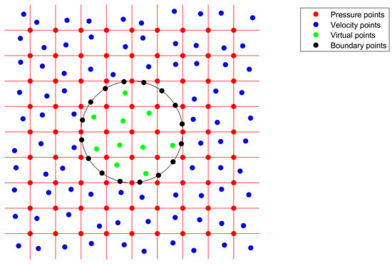
Figure 1.
Double-discretisation for the hybrid approach.
After performing the pressure correction according to Equation (4), the corrected velocities at the boundary and virtual points are not guaranteed to be zero; hence, the no-slip boundary condition and the virtually frozen status are not strictly satisfied. To solve this problem, Equation (4) is modified to
where represents the added discrete-time IB force averaged over the time step. The IB force only acts on the boundary and virtual points to enforce the fluid velocity to be the desired value of zero. Therefore, is obtained directly as
Accordingly, since is generally not divergence-free, the pressure Poisson equation should be modified to
It is worth mentioning that, in principle, the IB force can be applied only at the boundary points to save computation time. This is because the virtual points are not active in the first fraction step; enforcing the corrected velocity inside the immersed body to be zero or not has no impact on the numerical solution of velocity in the flow domain. Nevertheless, some tests have shown that this way of applying the IB force has non-negligible effects on the pressure field near the immersed boundary.
Now, the modified pressure Poisson Equation (20) is coupled with the IB force Equation (19). We here propose an iterative method to solve the coupled system. First, Equation (20) is solved by a direct method using the FFT. The derivatives in the right-hand side are evaluated at the pressure points using the WLS approximation based on the intermediate velocity and force values at the velocity points, the boundary points, and the virtual points. For the first iteration in the first time step, the IB force values are initialised to zero; otherwise, they are taken from those obtained from the previous time step or iteration. Then, the pressure gradients at the boundary and virtual points are calculated by the WLS approximation based on the pressure values obtained at the pressure points by the direct FFT-based method, and the force values are updated according to Equation (19). The iteration procedure continues till the numerical solution for converges. The convergence criterion is defined as that the mean-squared difference of the IB force magnitude between the present and previous iteration is below the tolerance times the mean-squared IB force magnitude of the previous iteration. Finally, at the last iteration of each time step, the pressure gradients at the velocity points are calculated as well to perform the pressure correction. It is important to note that, except for the first iteration, the evaluation of the right-hand side of the modified pressure Poisson equation needs to be performed only for these pressure points whose neighbours contain at least one boundary or virtual point (i.e., these pressure points in the vicinity or inside of the IB), hence being affected by the updated IB force values.
With the solution and the right-hand side evaluated on a regular grid of points, Equation (20) can be solved by either the pseudo-spectral method or the central finite-difference approximation [38]. For the two methods, the algorithm is equivalent and can be summarised as follows:
- Compute the coefficients of the right-hand side in the discrete Fourier modes using the forward one-dimensional discrete transforms sequentially on each separate dimension.
- Compute the coefficients of the solution in the discrete Fourier modes by dividing the coefficients obtained in Step 1 by the eigenvalues computed as the sum of one-dimensional eigenvalues.
- Transform the solution back to the basis of the grid point values using the backward one-dimensional discrete transforms sequentially on each separate dimension.
The efficiency of this algorithm comes from the use of the FFT to perform the discrete transforms. Different discrete Fourier transforms have to be used depending on the grid types (regular or staggered) and the boundary conditions (periodic, Dirichlet, Neumann). They can be found, for example, in Table 2 of [38]. The boundary conditions should have the same type in one direction and be homogeneous in the case of the Dirichlet or Neumann type. In addition to the dependence on the grid types and the boundary conditions, the eigenvalues depend on the methods. Those for the pseudo-spectral method are summarised in Table 3 of [38], and those for the central finite-difference method are summarised in Table 4 of [38]. Theoretically speaking, the hybrid FFT-based algorithm is not applicable in case the Neumann boundary condition is expressed by Equation (8) (non-homogeneous) rather than Equation (7) (homogeneous). A workaround on this issue is provided in the third example of the next section.
The whole simulation procedure for the projection method based on the hybrid pressure-correction algorithm is summarised by the flow chart shown in Figure 2.
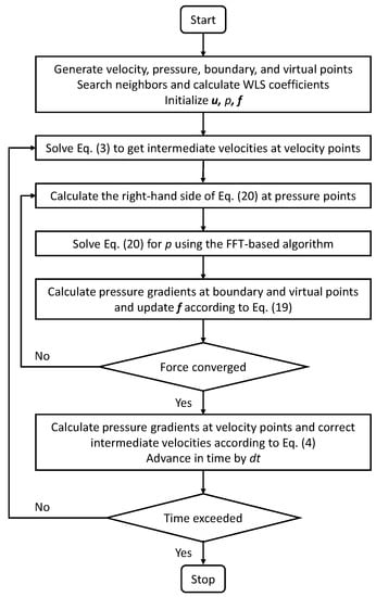
Figure 2.
Flow chart of the projection method using the hybrid pressure-correction algorithm.
3. Results
In this section, we verify and validate the new hybrid pressure-correction algorithm, which enables the FFT-based acceleration in the pressure Poisson solver, and compare its computational performance with the reference method in which the discrete pressure Poisson equation is solved by the aggregation-based algebraic multigrid method (AGMG) [34,35,36]. We recognise that there are several multigrid methods, and the present comparison is limited to AGMG, which outperforms several other state-of-the-art linear system solvers (see http://agmg.eu (accessed on 1 June 2023) for the technical details). Five canonical two-dimensional incompressible flows were simulated. They are laminar flow over a square with periodic lateral boundary conditions, laminar flow around a cylinder with periodic lateral boundary conditions, laminar flow past a cylinder between parallel plates, laminar flow over periodic triangular hills, and laminar flow in a lid-driven polar cavity. The purpose of the first test case was to check whether the methods/codes used in this study work correctly and whether the proposed hybrid algorithm influences the temporal and spatial accuracy of the underlying projection method. Test Cases 2–4 serve to have an extensive verification and performance evaluation of the proposed method under various boundary conditions, geometries, and Reynolds numbers. The fifth test case, for which experimental data are available, was used to validate the proposed hybrid algorithm. For each example (except for the convergence analysis), the number of points for spatial discretisation was chosen in a way such that a further increase of the grid resolution would not yield significant differences in the presented simulation results.
3.1. Flow over a Square
The first test case considered herein was the flow over a square with periodic boundary conditions in both horizontal and vertical directions. The geometry of the problem is shown in Figure 3, which consists of a single square cylinder of side length m and its associated volume within the square lattice of side length m.
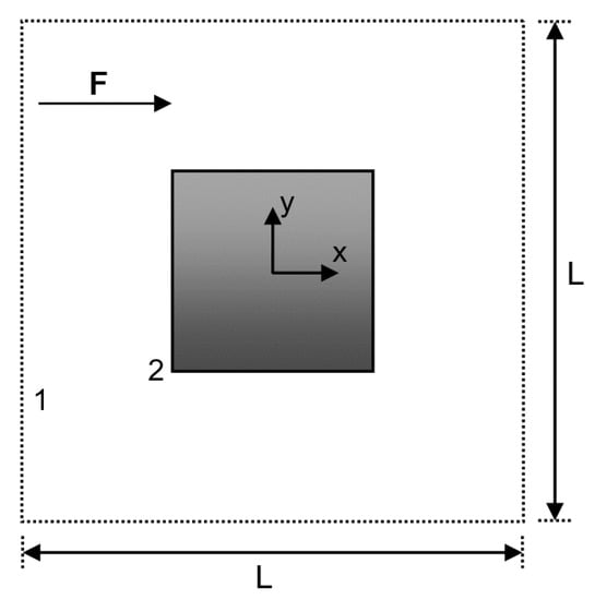
Figure 3.
Geometry of the flow over a square with periodic lateral boundary conditions. The side length of the square is m, and the side length of the square lattice is m. The two monitoring points 1 and 2 for comparing the time histories of numerical solutions are located at and , respectively.
The flow is driven by a body force along the horizontal direction. On the wall of the square cylinder, the no-slip boundary condition is imposed. The velocity field is initialised with zero values everywhere. The reference pressure was set to zero at the left-bottom corner. The kinematic viscosity was set to , and the body force was set to . The maximum horizontal velocity can reach about eventually. Based on , D, and , the Reynolds number () of this test case was about 300.
For the reference method, the computational domain was discretised with 134,079 velocity points in the flow region and 640 boundary points on the wall of the square cylinder. The number of pressure points generated in a staggered way was 134,400. For the hybrid method, the velocity and boundary points were the same as those for the reference method. In addition, 25,281 virtual points inside the square were generated, and a regular grid of points was used for solving the pressure Poisson equation. For both methods, the grid size was . The time step was set to s, which yielded the maximal CFL number of around 0.75. The flow was simulated up to s corresponding to 160,000 time steps. It turned out that the flow reached the steady-state after about 2000 s.
Figure 4 compares numerical solutions at obtained by the two methods for the horizontal velocity component U, the vertical velocity component V, and the pressure P. From a direct visual comparison, all these results showed excellent agreement between the solutions obtained by the hybrid method and the reference method. For a quantitative comparison, the relative difference for a flow variable between the two numerical solutions was computed as the root-mean-squared difference normalised by the root-mean-squared value of the variable from the reference solution. For the steady-state results, the relative differences for U, V, and P were , , and , respectively.
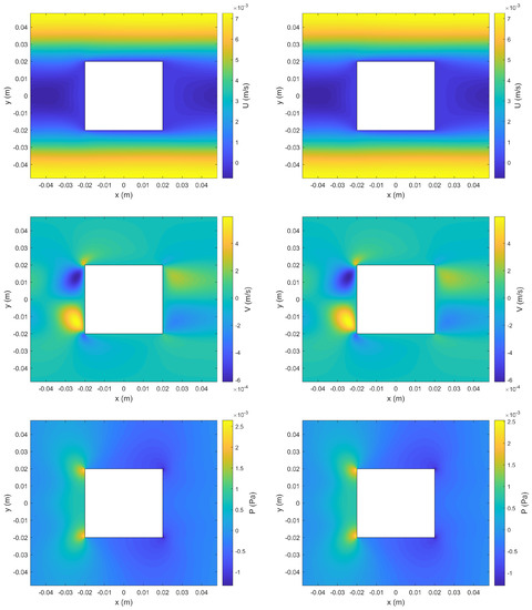
Figure 4.
Comparison of numerical solutions obtained by the reference method (left) and the hybrid method (right) for the first test case at s. Shown from top to bottom are the contours of the horizontal velocity component U, the vertical velocity component V, and the pressure P, respectively.
Figure 5 shows the time histories of U and V at Monitoring Point 1. Figure 6 shows the time histories of P at the two monitoring points 1 and 2. It turned out that the agreement between the numerical solutions from the two methods was also excellent with regard to the time evolution of these flow variables. The relative differences for , , , and were , , , and , respectively.
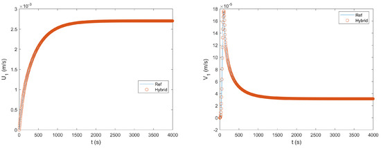
Figure 5.
Comparison of the time histories of the horizontal and vertical velocity components at Monitoring Point 1 obtained by the reference method and the hybrid method for the first test case.
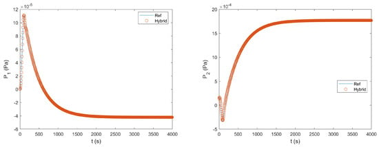
Figure 6.
Comparison of the time histories of the pressure at the two monitoring points 1 and 2 obtained by the reference method and the hybrid method for the first test case.
To further verify the correctness of the two methods above, the flow problem here was also simulated by using the commercial CFD software ANSYS Fluent. The spatial discretisation was performed by the standard finite volume method, and the time integration was performed by a second-order implicit scheme. The results obtained by ANSYS Fluent are not shown because they visually overlapped with those obtained by the hybrid and reference methods. The relative differences between the hybrid and Fluent solutions of U, V, and P were , , and , respectively. The relative differences between the reference and Fluent solutions of U, V, and P were , , and , respectively.
To assess the spatial accuracy of the hybrid and reference methods, simulations with larger grid sizes of , , and were performed. Using the steady-state solutions obtained with the smallest grid size (i.e., those shown in Figure 4) as references, the root-mean-squared errors for the solutions of coarser grids were computed.
Figure 7 shows the log–log plot of the errors as a function of the grid size for the horizontal velocity component U, the vertical velocity component V, and the pressure P. As indicated by the fit slope, the convergence rates for those flow variables were around 1.5. Therefore, for both the hybrid and reference methods, the spatial order of accuracy was lower than second order, although the spatial discretisation was based on the second-order Taylor’s expansion. It is reasonable to infer that the loss of accuracy was due to the WLS approximation.
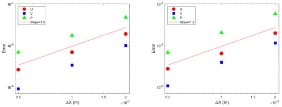
Figure 7.
Spatial error convergence for laminar flow over a square simulated by the reference (left) and hybrid (right) methods.
To assess the temporal accuracy of the hybrid and reference methods, simulations with the grid size fixed to and the time step varying from s to s were performed. Using the solutions at obtained with the smallest time step as references, the root-mean-squared errors for the solutions of larger time steps were computed.
Figure 8 shows the log–log plot of the errors as a function of the time step for the horizontal velocity component U, the vertical velocity component V, and the pressure P. As indicated by the fit slope, the temporal convergence rates for those flow variables were around 1. Therefore, for both the hybrid and reference methods, the temporal order of the accuracy was first order. This is consistent with the observation made by Aithal and Ferrante [21]: “We have observed that, in the presence of a no-slip wall, the numerically stiff viscous-diffusion term in the momentum equation of the incompressible Navier–Stokes equations causes loss of accuracy when integrated in time using the second-order Adams Bashforth method, and, in turn, the resulting solution for velocity is only first-order accurate in time”.
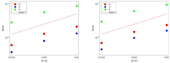
Figure 8.
Temporal error convergence for laminar flow over a square simulated by the reference (left) and hybrid (right) methods.
In summary, the results of this test case verified that the proposed hybrid pressure-correction algorithm is correct and it had no influence on the temporal and spatial accuracy of the underlying projection method. The latter was expected because the algorithm concerns only how to solve the pressure Poisson equation efficiently in the pressure-correction step.
3.2. Flow around a Cylinder
The second test case considered herein was the flow around a cylinder with periodic boundary conditions in both horizontal and vertical directions. This is equivalent to the flow through a periodic lattice of cylinders, which has been studied extensively as a simple model of flow through fibrous porous media. The geometry of the problem is shown in Figure 9, which consists of a single circular cylinder of radius r and its associated volume within the square lattice of side length L.
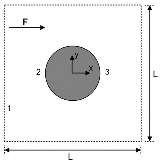
Figure 9.
Geometry of the flow around a cylinder with periodic lateral boundary conditions. The radius of the cylinder is m, and the side length of the square lattice is m. The three monitoring points 1, 2, and 3 for comparing the time histories of numerical solutions are located at , , and , respectively.
The flow is driven by a body force along the horizontal direction. On the wall of the cylinder, the no-slip boundary condition was imposed. The velocity field was initialised with zero values everywhere. The reference pressure was set to zero at the left-bottom corner. For the geometric parameters, we had m and m. The kinematic viscosity was set to , and the body force was set to . The maximum horizontal velocity can reach eventually. Based on , r, and , the Reynolds number of the flow simulated here was .
For the reference method, the computational domain was discretised with 139,552 velocity/pressure points in the flow region and 400 boundary points on the wall of the cylinder. For the hybrid method, the computational domain was discretised with 139,552 velocity points in the flow region, 400 boundary points on the wall of the cylinder, and 19,720 virtual points inside the cylinder. In addition, a regular grid of points was used for the pressure. For both methods, the average grid size was about . The time step was set to s, for which the corresponding maximal CFL number was about 0.6. The flow was simulated up to s, corresponding to 10,000 time steps.
Figure 10 compares the numerical solutions at obtained by the two methods for the horizontal velocity component U, the vertical velocity component V, and the pressure P. All these results showed excellent agreement between the solutions of the hybrid method and the reference method. The relative differences for U, V, and P were , , and , respectively. The time histories of U and V at Monitoring Point 1 are shown in Figure 11. The time histories of P at Monitoring Point 1 and the pressure difference between the two monitoring points 2 and 3 are shown in Figure 12. It turned out that the agreement between the numerical solutions from the two methods was also excellent with regard to the time evolution of these flow variables. The relative differences for , , , and were , , , and , respectively.
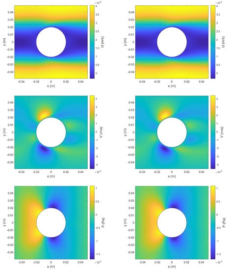
Figure 10.
Comparison of numerical solutions obtained by the reference method (left) and the hybrid method (right) for the second test case at s. Shown from top to bottom are the contours of the horizontal velocity component U, the vertical velocity component V, and the pressure P, respectively.
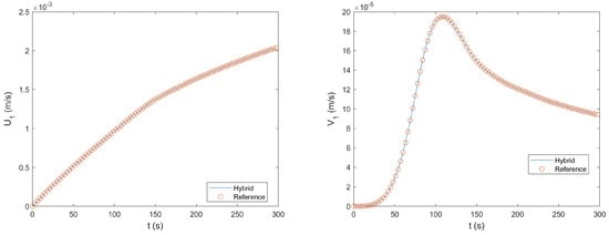
Figure 11.
Comparison of the time histories of the horizontal and vertical velocity components at Monitoring Point 1 obtained by the reference method and the hybrid method for the second test case.
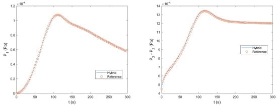
Figure 12.
Comparison of the time histories of the pressure at Monitoring Point 1 and the pressure difference between the two monitoring points 2 and 3 obtained by the reference method and the hybrid method for the second test case.
For the hybrid method, the results presented in Figure 10, Figure 11 and Figure 12 were obtained with the pressure Poisson equation solved by the central finite-difference approximation on a regular grid and the tolerance for the IB force iteration set to . To check the grid convergence of numerical solutions, we performed a simulation using the hybrid method with the grid resolution increased by a factor of and the time step reduced to s. The results from this simulation matched very well with those from the two presented simulations of coarser resolutions. Additionally, to check the robustness of the hybrid method, we performed three more simulations: one with a smaller tolerance of , one using a staggered grid for pressure, and one with the pressure Poisson equation solved by the pseudo-spectral method. None of them yielded noticeable differences when compared to the results presented here.
On a computer with Intel Broadwell processors running at 2.6 GHz, the total wall clock time of the hybrid solver was about 805 s and the total wall clock time of the reference solver was about 1747 s. It is important to note that the simulation time spent in the first fractional step was not taken into account in the comparison of the computational performance because the two methods share the same algorithm in this part. The hybrid solver was more than faster than the reference solver. Nevertheless, the speedup depends on the tolerance for the AGMG solver and the tolerance for the IB force iteration. Here, the former was set to (the value recommended in the AGMG application examples) and the latter was set to . Theoretically, this choice can be justified by the fact that the pressure Poisson equation in the hybrid method was solved directly; hence, convergence was not an issue, and the IB force convergence only affected the velocity field locally around the immersed body. Practically, it was observed that further lowering the tolerance for the IB force iteration made no improvement to the results, while further lowering the tolerance for the AGMG solver led to noticeable pressure oscillations. It is worth mentioning that a coarser pressure grid can be used in the hybrid solver to further speed up the simulation. A test using a pressure grid of points showed that the total wall clock time of the hybrid solver was reduced to 496 s to yield a speedup of about three and half times, while the overall simulation accuracy was not considerably worsened, namely there were no obvious differences when comparing the results from this simulation to the standard ones.
In this study, both the hybrid and reference solvers were not implemented in parallel. According to the comparative study of state-of-the-art parallel Poisson solvers by Gholami et al. (2016) [39], FFT-based parallel solvers can be two orders of magnitude faster than multigrid-based parallel solvers. Moreover, a rectangular computational domain is favourable for parallel computing because straightforward and efficient domain decomposition techniques such as slab or pencil decomposition can be applied. Therefore, the proposed hybrid pressure-correction algorithm has a great potential to result in a high-performance parallel computational fluid dynamics (CFD) solver for incompressible flows.
3.3. Flow Past a Cylinder between Parallel Plates
In the third numerical example, laminar flow past a cylinder between two parallel plates was simulated using the proposed hybrid method, and the results were compared with those obtained by the reference method. The geometry of the problem was the same as that shown in Figure 9. The flow was driven by a body force along the horizontal direction. Periodic boundary conditions were applied in the horizontal direction. No-slip boundary conditions were imposed at the top and bottom boundaries and the wall of the cylinder. For solving the pressure Poisson equation in the hybrid method, it can be shown that, with the staggered grid and central difference scheme, at the top and bottom boundaries cancelled out in the final algebraic equations for the pressures at the internal grid points; therefore, their values can be effectively set to zero for the calculations in which they are involved. This justifies the use of the Neumann boundary condition specified by Equation (7) at the top and bottom wall boundaries, and consequently the application of the FFT-based solver. If needed, the pressures on the top and bottom boundaries can be calculated using Equation (8) with the values of as they are. It is worth mentioning that the IB force was not applied at a boundary where the Neumann boundary condition was imposed. The velocity field was initialised with zero values everywhere. The reference pressure is set to zero at the left-bottom corner. The geometric and physical parameters were the same as those of the second test case. With this setting, the maximum horizontal velocity can reach about eventually. Based on , r, and , the Reynolds number of the flow simulated here was about .
The computational domain was discretised with 139,142 points in the flow region and 1200 boundary points at the top, bottom, and cylinder boundaries for the reference method, additional 19,756 virtual points inside the cylinder, and a staggered pressure grid of points for the hybrid method. The average grid size was about . The time step was set to s to ensure numerical stability, for which the corresponding maximal CFL number was about 0.3. The flow was simulated up to s corresponding to 10,000 time steps. The tolerance for the IB force iteration was set to .
Figure 13 compares the numerical solutions at obtained by the two methods for the horizontal velocity component U, the vertical velocity component V, and the pressure P. Figure 14 and Figure 15 show the time histories of U, V, and P at the selected monitoring points indicated in Figure 9. Like in the second test case, all these results showed excellent agreement between the solution of the hybrid method and that of the reference method. The relative differences for the flow variables shown here were below . Furthermore, our tests showed that, for the hybrid method, the simulation results were not sensitive to the choice of the method (pseudo-spectra or finite difference) and grid (regular or staggered) for solving the pressure Poisson equation.
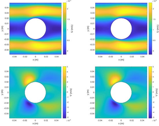
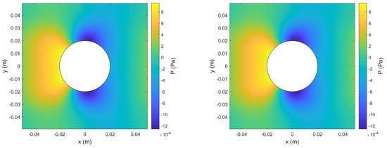
Figure 13.
Comparison of numerical solutions obtained by the reference method (left) and the hybrid method (right) for the third test case at s. Shown from top to bottom are the contours of the horizontal velocity component U, the vertical velocity component V, and the pressure P, respectively.
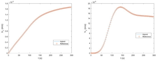
Figure 14.
Comparison of the time histories of the horizontal and vertical velocity components at Monitoring Point 1 obtained by the reference method and the hybrid method for the third test case.
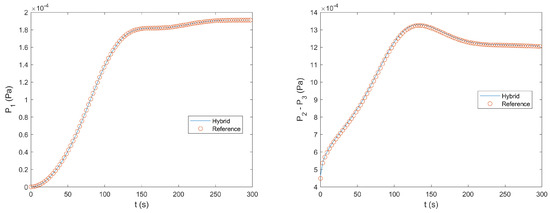
Figure 15.
Comparison of the time histories of the pressure at Monitoring Point 1 and the pressure difference between the two monitoring points 2 and 3 obtained by the reference method and the hybrid method for the third test case.
The total wall clock time of the hybrid solver was about 840 s, and the total wall clock time of the reference solver was about 1622 s. The hybrid solver was about twice as fast as the reference solver. To have a further speedup, a coarser grid (e.g., ) can be used to solve the pressure Poisson equation without deteriorating the overall simulation accuracy.
3.4. Flow over Periodic Triangular Hills
In the last verification case, we applied the hybrid and reference methods to simulate a well-defined flow passing over a series of triangular hills, which repeat along a channel in a periodic fashion. Figure 16 shows a schematic of the flow domain.
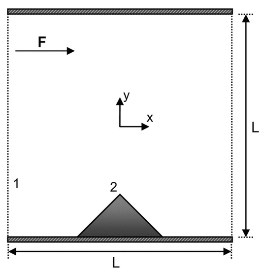
Figure 16.
Geometry of the flow over periodic triangular hills in a channel. The height of the hill is m, and the width of the hill is m. The height of the channel is m. The two monitoring points 1 and 2 for comparing the time histories of numerical solutions are located at and , respectively.
The flow was driven by a body force along the horizontal direction. Periodic boundary conditions were applied in the horizontal direction. No-slip boundary conditions were imposed at the top and bottom boundaries and the surface of the hill. The velocity field was initialised with zero values everywhere. The reference pressure was set to zero at the left-bottom corner. For the geometric parameters, the height of the channel was m and the height of the hill was m. The kinematic viscosity was set to , and the body force was set to . With this setting, the flow would eventually develop to a state comprising a time-periodic motion. The maximum horizontal velocity was about . Based on , h, and , the Reynolds number of the flow simulated here was about 800.
For the reference method, the computational domain was discretised with 153,200 velocity points in the flow region and 800 boundary points. The number of pressure points generated in a staggered fashion was 153,681. For the hybrid method, the velocity and boundary points were the same as those for the reference method. In addition, 7200 virtual points beneath the bottom boundary and the hill surface were generated, and a regular grid of points was used for solving the pressure Poisson equation. Here, a small portion of the regular grid was below the bottom boundary. For both methods, the grid size was about . The time step was set to s, for which the corresponding maximal CFL number was about 0.8. The flow was simulated for a sufficiently long time to ensure the time-periodic solution was fully developed.
Figure 17 compares numerical solutions at a given time obtained by the two methods for the horizontal velocity component U, the vertical velocity component V, and the pressure P. Figure 18 and Figure 19 show the time histories of U, V, and P at the selected monitoring points indicated in Figure 16. It can be seen that the flow was periodic in time. Like in the previous test cases, all these results showed excellent agreement between the solution of the hybrid method and that of the reference method. The relative differences for U, V, and P were , , and , respectively. The relative differences for , , , and were , , , and , respectively.
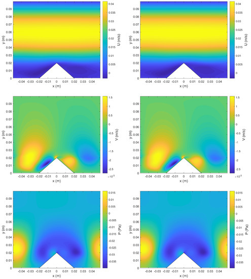
Figure 17.
Comparison of numerical solutions obtained by the reference method (left) and the hybrid method (right) for the fourth test case at the time when the horizontal velocity at Monitoring Point 1 reaches the median in the accelerating phase. Shown from top to down are the contours of the horizontal velocity component U, the vertical velocity component V, and the pressure P, respectively.
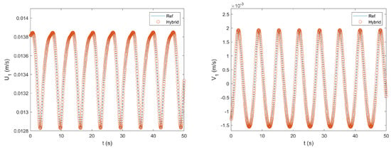
Figure 18.
Comparison of time histories of the horizontal and vertical velocity components at Monitoring Point 1 obtained by the reference method and the hybrid method for the fourth test case.
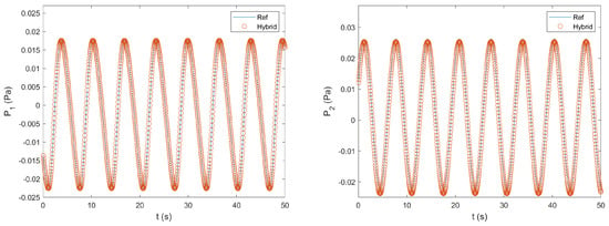
Figure 19.
Comparison of time histories of the pressure at the two monitoring points 1 and 2 obtained by the reference method and the hybrid method for the fourth test case.
For a simulation of 10,000 time steps, the total wall clock time of the hybrid solver was about 840 s, and the total wall clock time of the reference solver was about 2075 s. The hybrid solver was faster than the reference solver. In other words, the speedup of the hybrid solver was 2.47 times.
3.5. Lid-Driven Polar Cavity
In order to validate the proposed hybrid method, the lid-driven polar cavity flow was here simulated, which was first studied both experimentally and numerically by Fuchs and Tillmark [40]. As shown in Figure 20, the flow was in an annular region defined by and . No-slip boundary conditions were applied at the four boundaries of the flow domain. For the rotating wall at , an azimuthal velocity of was prescribed. The dimensionless geometrical and physical parameters matching the experiments [40] were set as:
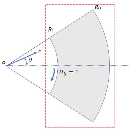
Figure 20.
Schematic of the geometry for the lid-driven polar cavity flow. The flow is driven by the moving wall at , and the polar cavity is defined by and . The red dashed rectangle indicates the extended computational domain for solving the pressure Poisson equation.
The flow domain was discretised with 59,501 velocity points and 1000 boundary points. In addition, inside the extended rectangular domain, but outside the four boundaries of the flow domain, 75,106 virtual points were generated. The pressure Poisson equation was solved in the extended rectangular domain using a regular grid of points. It is important to point out that, unlike the previous test cases, enforcing the divergence-free constraint outside the flow domain could be problematic in this case because a part of the solid body is moving. Hence, we chose to introduce a source/sink term outside the flow domain, which effectively turned the right-hand side of the Poisson equation into zero for the pressure points outside the flow domain. The dimensionless grid size was about 0.005. To ensure numerical stability, the dimensionless time step was set to , and the corresponding maximal CFL number was about 0.2. An initial condition of zero velocity was applied in the interior of the cavity. The flow was simulated for a sufficiently long time to ensure that the steady-state was reached. Figure 21 shows the radial () and azimuthal () velocity profiles along four radial lines , and for Re = 410, 280, 380, and 340, respectively, in comparison with the experimental data of Fuchs and Tillmark [40]. In all four cases, the simulation results obtained by the hybrid method were in good agreement with the experimental results, which also validated the proposed hybrid algorithm. As a side note, the simulation results here were also consistent with those obtained by the other numerical methods (for example, see Figure 18 of [21]).
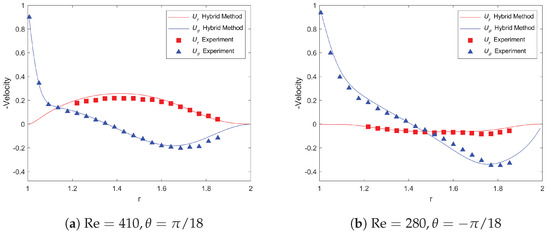
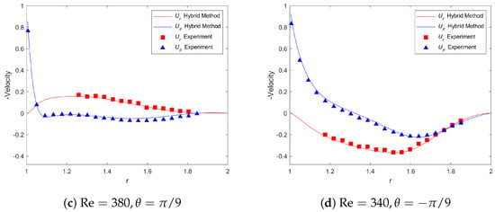
Figure 21.
Comparison of the radial and azimuthal velocity components along four radial lines for the lid-driven polar cavity flow at different Reynolds numbers.
4. Conclusions and Future Work
A new hybrid pressure-correction algorithm was developed for applying projection methods to simulate unsteady incompressible flows with the presence of obstacles. The hybrid algorithm combines different numerical methods and associated spatial discretisations in the pressure-correction step of projection methods, and it was demonstrated/implemented in a classical second-order time-marching projection scheme together with a meshless method with the irregular distribution of points for solving the momentum equations. The key of the hybrid algorithm relies on adopting a double-grid system and combining the weighted least-squares approximation with the idea inspired by immersed boundary methods. Such a design makes it feasible to solve the pressure Poisson equation on a regular grid for flow problems of obstacles. Hence, the solution process can be accelerated by using the FFT while keeping the implementation of the boundary conditions as easy as body-conforming numerical methods do with structured or unstructured grids. The numerical simulations of five test cases with different boundary conditions, geometries, and Reynolds numbers were performed to verify and validate the proposed methodology. The results showed that the new hybrid algorithm works and is robust, and as expected, it had no influence on the temporal and spatial accuracy of the underlying projection method. In terms of computational performance, the hybrid method outperformed the reference method, which adopts the same temporal and spatial discretisation schemes in the first sub-step as the hybrid method does, but solves the pressure Poisson equation in the second sub-step in the conventional way with a multigrid-based method. It was shown that, without deteriorating the overall simulation accuracy, a three-times speedup can be achieved by the hybrid method by setting the tolerance value to for the IB force iteration and using a grid for pressure coarser than that for velocity.
Although the proposed hybrid algorithm was here demonstrated/implemented in the classical second-order Adams–Bashforth-based projection method, it can be readily implemented in other projection schemes such as high-order Runge–Kutta-based projection methods. Furthermore, the numerical method in the first fractional step is not necessarily of the meshless type, and it can be a mesh-based method such as finite-volume. Considering the facts that domain decomposition techniques/libraries for rectangular domains are mature and efficient and with which FFT-based parallel Poisson solvers can be two orders of magnitude faster than multigrid-based parallel Poisson solvers, the hybrid algorithm provides a promising alternative for developing next-generation high-performance parallel CFD solvers for incompressible flows.
In future work, the hybrid framework will be tested in high-order projection methods, implemented with parallel computing, and extended for three-dimensional turbulent flows and large-eddy simulation of atmospheric boundary layers over complex terrain. Ultimately, this work will serve as the basis for a high-performance parallel incompressible flow solver.
Funding
This research received no external funding.
Data Availability Statement
The data presented in this study are available upon request from the corresponding author.
Acknowledgments
This work was facilitated though the use of advanced computational infrastructure provided by the Scientific IT and Application Support (SCITAS) platform at the Swiss Federal Institute of Technology in Lausanne (EPFL).
Conflicts of Interest
The authors declare no conflict of interest.
Abbreviations
The following abbreviations are used in this manuscript:
| AGMG | Aggregation-based algebraic multigrid method |
| CFD | Computational fluid dynamics |
| CFL | Courant–Friedrichs–Lewy |
| DNS | Direct numerical simulation |
| FFT | Fast Fourier transform |
| IBM | Immersed boundary method |
| LES | Large-eddy simulation |
| RK | Runge–Kutta |
| SPH | Smoothed particle hydrodynamics |
| WLS | Weighted least squares |
References
- Chorin, A. Numerical solution of the navier-stokes equations. Math. Comput. 1968, 22, 745–762. [Google Scholar] [CrossRef]
- Temam, R. Une méthode d’approximation de la solution des équations de Navier–Stokes. Bull. Soc. Math. France 1968, 98, 115–152. [Google Scholar] [CrossRef]
- Guermond, J.; Minev, P.; Shen, J. An overview of projection methods for incompressible flows. Comput. Methods Appl. Mech. Eng. 2006, 195, 6011–6045. [Google Scholar] [CrossRef]
- Bell, J.; Colella, P.; Glaz, H. A second-order projection method for the incompressible navier-stokes equations. J. Comput. Phys. 1989, 85, 257–283. [Google Scholar] [CrossRef]
- Brown, D.; Cortez, R.; Minion, M. Accurate Projection Methods for the Incompressible Navier–Stokes Equations. J. Comput. Phys. 2001, 168, 464–499. [Google Scholar] [CrossRef]
- Kim, J.; Moin, P. Application of a fractional-step method to incompressible Navier–Stokes equations. J. Comput. Phys. 1985, 59, 308–323. [Google Scholar] [CrossRef]
- Albertson, J.; Parlange, M. Surface length scales and shear stress: Implications for land-atmosphere interaction over complex terrain. Water Resour. Res. 1999, 35, 2121–2132. [Google Scholar] [CrossRef]
- Capuano, F.; Coppola, G.; Chiatto, M.; De Luca, L. Approximate projection method for the incompressible navier-stokes equations. AIAA J. 2016, 54, 2178–2181. [Google Scholar] [CrossRef]
- Liu, M.; Ren, Y.X.; Zhang, H. A class of fully second order accurate projection methods for solving the incompressible Navier–Stokes equations. J. Comput. Phys. 2004, 200, 325–346. [Google Scholar] [CrossRef]
- Laizet, S.; Lamballais, E. High-order compact schemes for incompressible flows: A simple and efficient method with quasi-spectral accuracy. J. Comput. Phys. 2009, 228, 5989–6015. [Google Scholar] [CrossRef]
- Laizet, S.; Li, N. Incompact3d: A powerful tool to tackle turbulence problems with up to O(105) computational cores. Int. J. Numer. Methods Fluids 2011, 67, 1735–1757. [Google Scholar] [CrossRef]
- Duran, A.; Giometto, M.; Park, G.; Moin, P. Non-equilibrium three-dimensional boundary layers at moderate Reynolds numbers. J. Fluid Mech. 2019, 883, A20. [Google Scholar] [CrossRef]
- Wu, Z.; Laurence, D.; Afgan, I. Direct numerical simulation of a low momentum round jet in channel crossflow. Nucl. Eng. Des. 2017, 313, 273–284. [Google Scholar] [CrossRef]
- Moeng, C.H. A large- eddy-simulation model for the study of planetary boundary-layer turbulence. J. Atmos. Sci. 1984, 41, 2052–2062. [Google Scholar] [CrossRef]
- Cheng, W.C.; Yang, Y. Scaling of flows over realistic urban geometries: A large-eddy simulation study. Bound.-Layer Meteorol. 2023, 186, 125–144. [Google Scholar] [CrossRef]
- Cummins, S.J.; Rudman, M. An SPH Projection Method. J. Comput. Phys. 1999, 152, 584–607. [Google Scholar] [CrossRef]
- Lo, E.Y.; Shao, S. Simulation of near-shore solitary wave mechanics by an incompressible SPH method. Appl. Ocean Res. 2002, 24, 275–286. [Google Scholar] [CrossRef]
- Salehizadeh, A.; Shafiei, A. A Coupled ISPH-TLSPH Method for Simulating Fluid-Elastic Structure Interaction Problems. J. Mar. Sci. Appl. 2022, 21, 15–36. [Google Scholar] [CrossRef]
- Le, H.; Moin, P. An improvement of fractional step methods for the incompressible Navier–Stokes equations. J. Comput. Phys. 1991, 92, 369–379. [Google Scholar] [CrossRef]
- de Michele, C.; Capuano, F.; Coppola, G. Fast-Projection Methods for the Incompressible Navier–Stokes Equations. Fluids 2020, 5, 222. [Google Scholar] [CrossRef]
- Aithal, A.; Ferrante, A. A fast pressure-correction method for incompressible flows over curved walls. J. Comput. Phys. 2020, 421, 109693. [Google Scholar] [CrossRef]
- Karam, M.; Sutherland, J.; Saad, T. Low-cost Runge-Kutta integrators for incompressible flow simulations. J. Comput. Phys. 2021, 443, 110518. [Google Scholar] [CrossRef]
- Dodd, M.; Ferrante, A. A fast pressure-correction method for incompressible two-fluid flows. J. Comput. Phys. 2014, 273, 416–434. [Google Scholar] [CrossRef]
- Fourtakas, G.; Rogers, B.; Nasar, A. Towards pseudo-spectral incompressible smoothed particle hydrodynamics (ISPH). Comput. Phys. Commun. 2021, 266, 108028. [Google Scholar] [CrossRef]
- Mittal, R.; Iaccarino, G. Immersed boundary methods. Annu. Rev. Fluid Mech. 2005, 37, 239–261. [Google Scholar] [CrossRef]
- Chester, S.; Meneveau, C.; Parlange, M. Modeling turbulent flow over fractal trees with renormalized numerical simulation. J. Comput. Phys. 2007, 225, 427–448. [Google Scholar] [CrossRef]
- Ma, H.; Cheng, W.C. Effects of unstable thermal stratification on the flow characteristics in an idealized rural-to-urban transition region: A large-eddy simulation study. Build. Environ. 2023, 230, 109971. [Google Scholar] [CrossRef]
- Ma, Y.; Liu, H. Large-Eddy Simulations of Atmospheric Flows Over Complex Terrain Using the Immersed-Boundary Method in the Weather Research and Forecasting Model. Bound.-Layer Meteorol. 2017, 165, 421–445. [Google Scholar] [CrossRef]
- Liu, L.; Stevens, R. Wall modeled immersed boundary method for high Reynolds number flow over complex terrain. Comput. Fluids 2020, 208, 104604. [Google Scholar] [CrossRef]
- Fang, J.; Porté-Agel, F. Intercomparison of terrain-following coordinate transformation and immersed boundary methods in large-eddy simulation of wind fields over complex terrain. J. Phys. Conf. Ser. 2016, 753, 082008. [Google Scholar] [CrossRef]
- Fang, J.; Parriaux, A. A regularized Lagrangian finite point method for the simulation of incompressible viscous flows. J. Comput. Phys. 2008, 227, 8894–8908. [Google Scholar] [CrossRef]
- Hockney, R.W.; Eastwood, J.W. Computer Simulation Using Particles; McGraw-Hill: New York, NY, USA, 1981. [Google Scholar]
- Press, W.H.; Teukolsky, S.A.; Vetterling, W.T.; Flannery, B.P. Numerical Recipes in FORTRAN: The Art of Scientific Computing, 2nd ed.; Cambridge University Press: Cambridge, UK, 1992. [Google Scholar]
- Notay, Y. An aggregation-based algebraic multigrid method. Electron. Trans. Numer. Anal. 2010, 37, 123–146. [Google Scholar]
- Napov, A.; Notay, Y. An algebraic multigrid method with guaranteed convergence rate. SIAM J. Sci. Comput. 2012, 34, A1079–A1109. [Google Scholar] [CrossRef]
- Notay, Y. Aggregation-based algebraic multigrid for convection-diffusion equations. SIAM J. Sci. Comput. 2012, 34, A2288–A2316. [Google Scholar] [CrossRef]
- Fang, J.; Diebold, M.; Higgins, C.; Parlange, M. Towards oscillation-free implementation of the immersed boundary method with spectral-like methods. J. Comput. Phys. 2011, 230, 8179–8191. [Google Scholar] [CrossRef]
- Fuka, V. PoisFFT—A free parallel fast Poisson solver. Appl. Math. Comput. 2015, 267, 356–364. [Google Scholar] [CrossRef]
- Gholami, A.; Malhotra, D.; Sundar, H.; Biros, G. FFT, FMM, or Multigrid? A comparative Study of State-Of-the-Art Poisson Solvers for Uniform and Nonuniform Grids in the Unit Cube. SIAM J. Sci. Comput. 2016, 38, C280–C306. [Google Scholar] [CrossRef]
- Fuchs, L.; Tillmark, N. Numerical and experimental study of driven flow in a polar cavity. Int. J. Numer. Methods Fluids 1985, 5, 311–329. [Google Scholar] [CrossRef]
Disclaimer/Publisher’s Note: The statements, opinions and data contained in all publications are solely those of the individual author(s) and contributor(s) and not of MDPI and/or the editor(s). MDPI and/or the editor(s) disclaim responsibility for any injury to people or property resulting from any ideas, methods, instructions or products referred to in the content. |
© 2023 by the author. Licensee MDPI, Basel, Switzerland. This article is an open access article distributed under the terms and conditions of the Creative Commons Attribution (CC BY) license (https://creativecommons.org/licenses/by/4.0/).