Dual Function Behavior of Carbon Fiber-Reinforced Polymer in Simulated Pore Solution

Abstract
:1. Introduction
2. Experimental Details
2.1. Materials


| Ingredients | Concentration (%) |
|---|---|
| Bisphenol-A type epoxy resin | 37–38 |
| Novolac epoxy resin | 19–20 |
| Dicyandiamide | 5–6 |
| Methyl ethyl ketone (MEK) | 36–37 |
2.2. Testing Methods
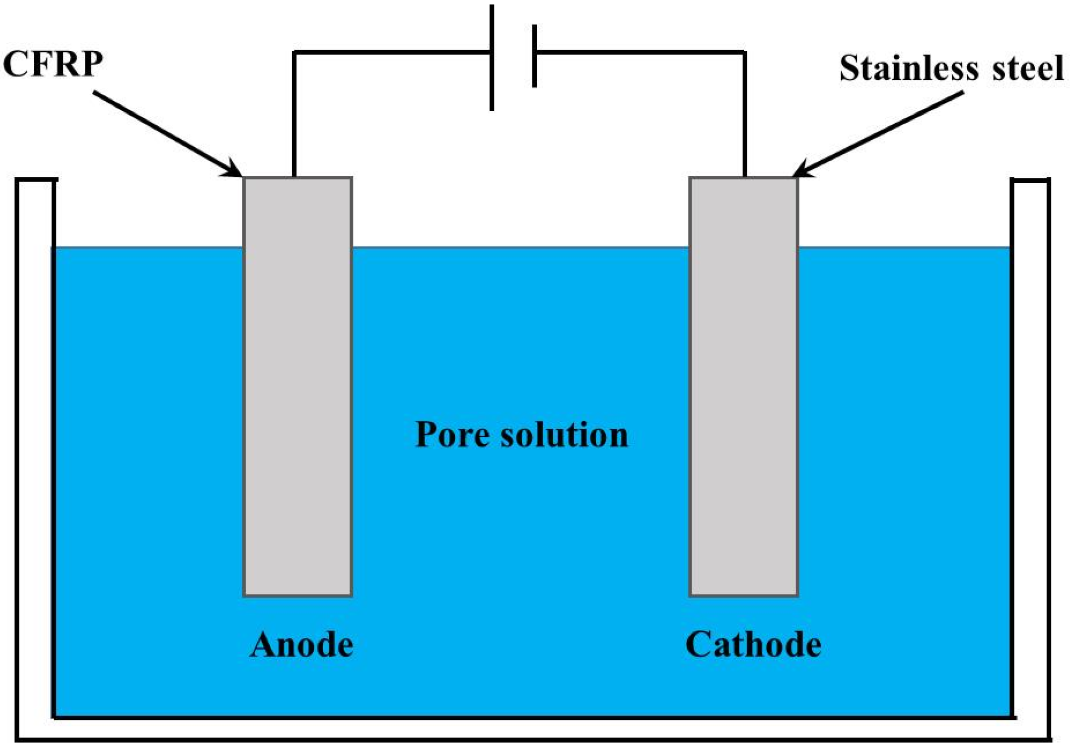
2.2.1. Accelerated Polarization Test
| Ingredients | Concentration (%) |
|---|---|
| Ca(OH)2 | 0.2 |
| KCl | 3.2 |
| NaOH | 2.45 |
| KOH | 1 |
| Distilled water | 93.15 |
| Specimen | As (mm2) | Ac (mm2) | i (A/m2) | q (107 C/m2) | fu (MPa) | Failure Modes | KExp | KCal/KExp |
|---|---|---|---|---|---|---|---|---|
| I0D25 | 670.40 | 25.56 | 0 | 0 | 774.79 | L | – | – |
| I0D25# | 669.63 | 25.66 | 0 | 0 | 649.71 | L | – | – |
| I0.5D25 | 642.64 | 25.19 | 0.889 | 0.192 | 675.58 | L | 0.99 | 0.92 |
| I0.5D25# | 616.17 | 25.30 | 0.926 | 0.200 | 699.42 | L | 1.02 | 0.89 |
| I1D25 | 578.82 | 26.18 | 1.888 | 0.408 | 559.89 | L | 0.82 | 1.00 |
| I1D25# | 657.50 | 25.97 | 1.637 | 0.354 | 549.92 | L | 0.80 | 1.05 |
| I2D25 | 646.07 | 25.71 | 3.085 | 0.666 | 513.21 | D | 0.75 | 0.96 |
| I2D25# | 656.75 | 26.27 | 3.024 | 0.653 | 477.16 | D | 0.70 | 1.04 |
| I4D25 | 656.25 | 25.27 | 6.066 | 1.310 | 474.00 | D | 0.69 | 0.76 |
| I4D25# | 630.48 | 26.07 | 6.355 | 1.373 | 466.77 | D | 0.68 | 0.75 |
| I0D50 | 671.16 | 25.23 | 0 | 0 | 682.09 | L | – | – |
| I0D50# | 668.61 | 25.79 | 0 | 0 | 627.16 | L | – | – |
| I0.5D50 | 644.60 | 25.45 | 0.887 | 0.383 | 653.59 | L | 0.96 | 0.87 |
| I1D50 | 657.25 | 25.70 | 1.611 | 0.696 | 318.15 | D | 0.47 | 1.53 |
| I1D50# | 643.62 | 24.83 | 1.666 | 0.720 | 340.22 | D | 0.50 | 1.41 |
| I2D50 | 656.75 | 25.09 | 2.981 | 1.288 | 329.08 | D | 0.48 | 1.11 |
| I2D50# | 630.72 | 25.69 | 3.110 | 1.344 | 303.17 | D | 0.44 | 1.17 |
| I4D50 | 632.64 | 26.23 | 6.354 | 2.745 | 193.49 | D | 0.28 | 0.93 |
| I4D50# | 618.76 | 26.00 | 6.424 | 2.775 | 181.88 | D | 0.27 | 0.97 |
| Mean | – | – | – | – | – | – | – | 1.02 |
| COV | – | – | – | – | – | – | – | 0.211 |
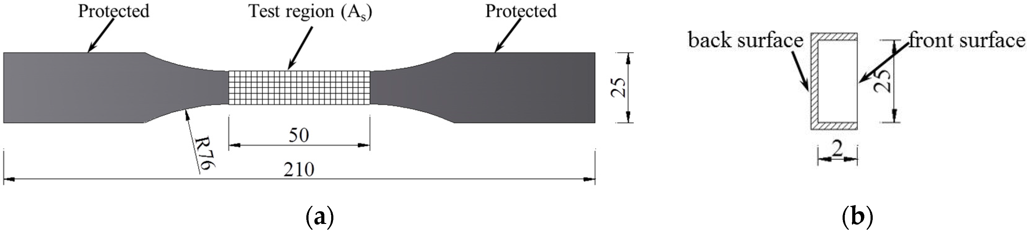
2.2.2. Tensile Test
3. Results and Discussion
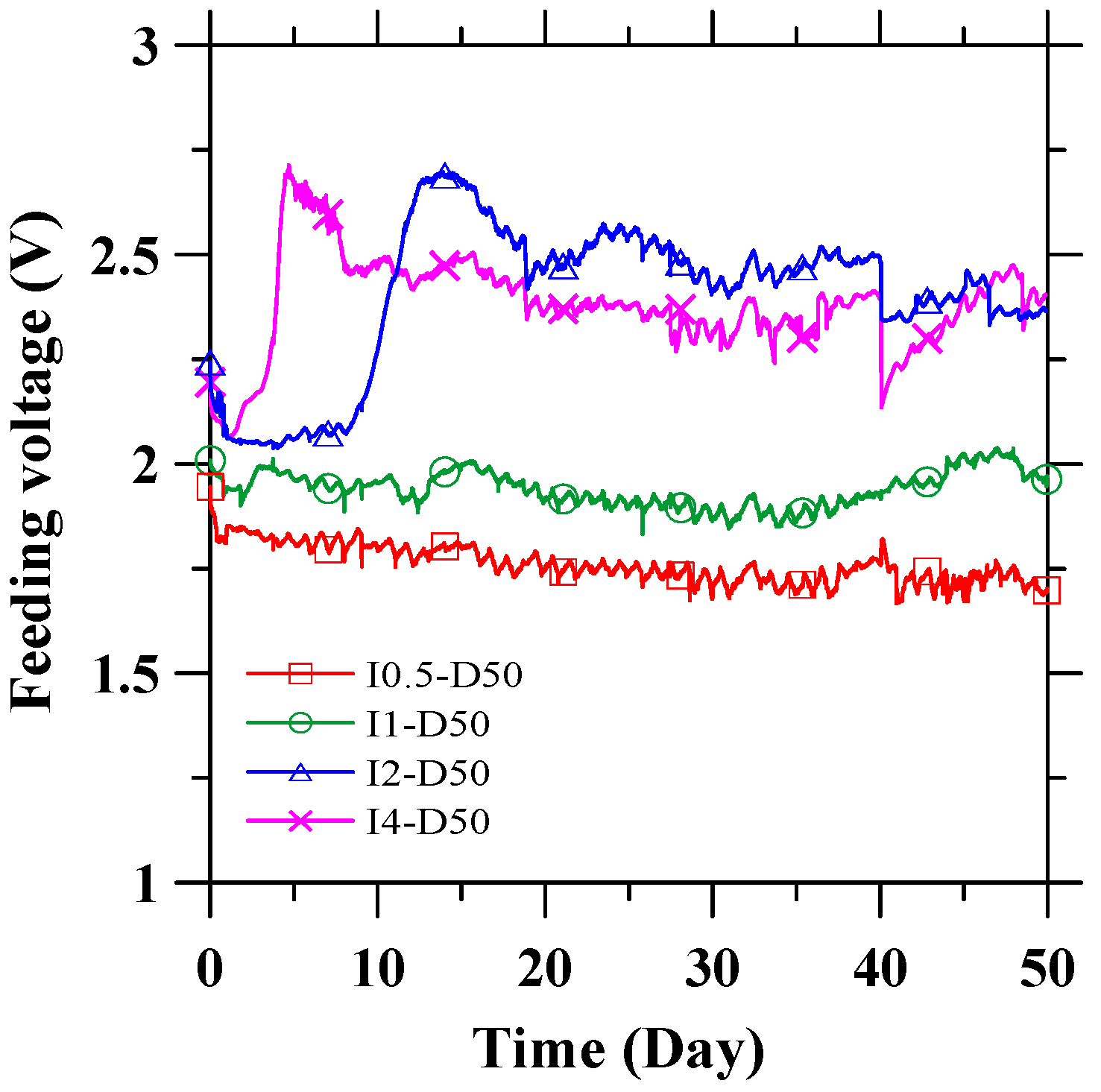
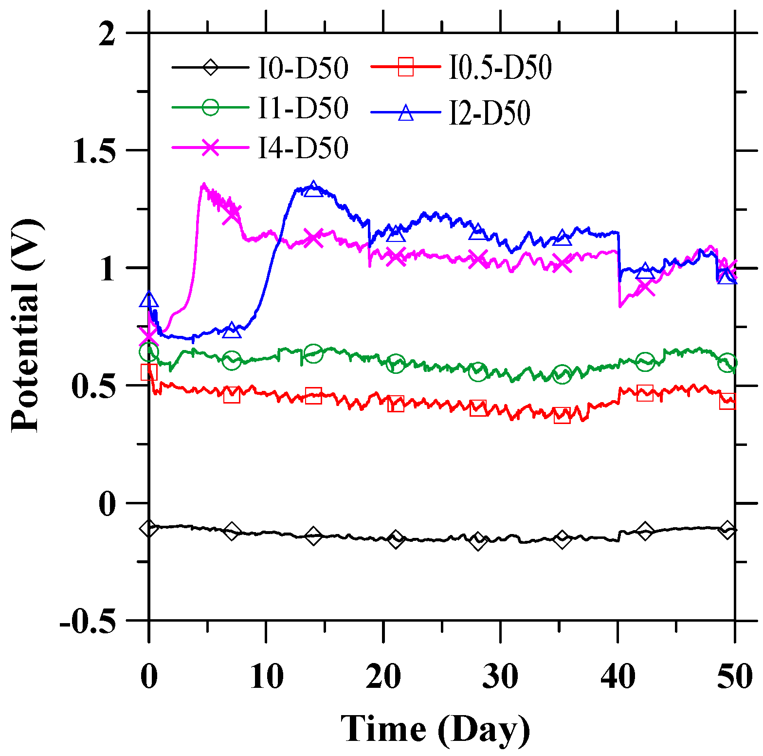
3.1. Anode Performance


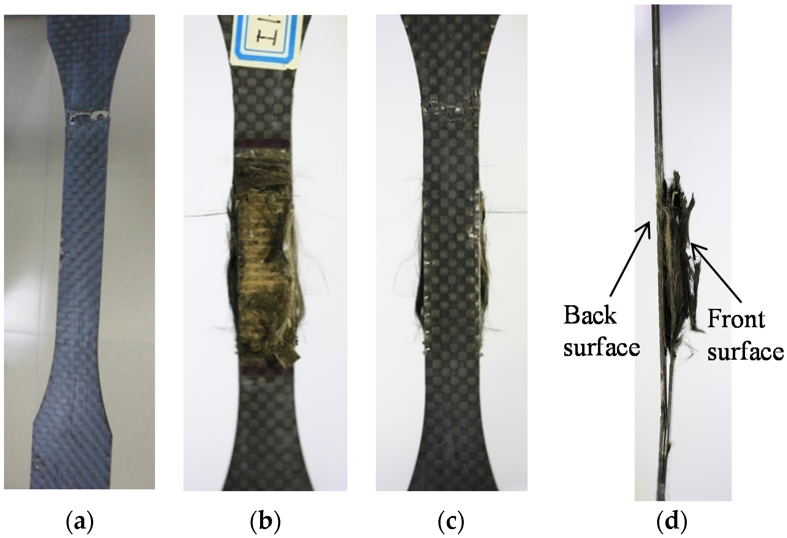
3.2. Tensile Strength and Failure Modes

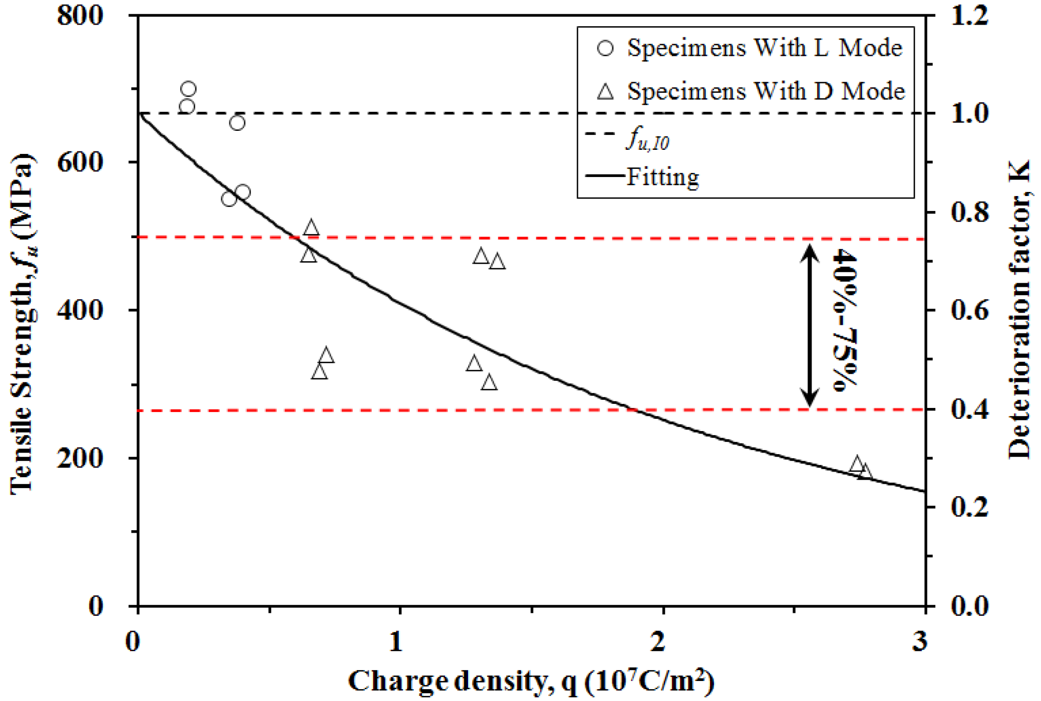
3.3. Relationship between Tensile Strength and Charge Density
4. Discussion of Service Life
5. Conclusions
- 1
- The recorded feeding voltage indicated that an ICCP system with a CFRP anode could operate stably in a pore solution. Meanwhile, the anode performance of CFRP was maintained for 50 days of polarization with applied current densities reaching 6.15 A/m2, as indicated by the stabilized potential curve of CFRP.
- 2
- The mechanical properties of the CFRP specimens were obtained from uniaxial tensile tests after anodic polarization. The tensile strengths of CFRP decreased with increased charge densities. The failure mode of CFRP after polarization transferred from lateral to edge delamination with increased impressed current densities and test durations. The impressed charge density significantly affected the mechanical properties of CFRP.
- 3
- A model was developed based on the experimental results in order to calculate the CFRP tensile strengths at given impressed charge densities. Agreement was obtained between the calculated tensile strengths and the experimental data.
- 4
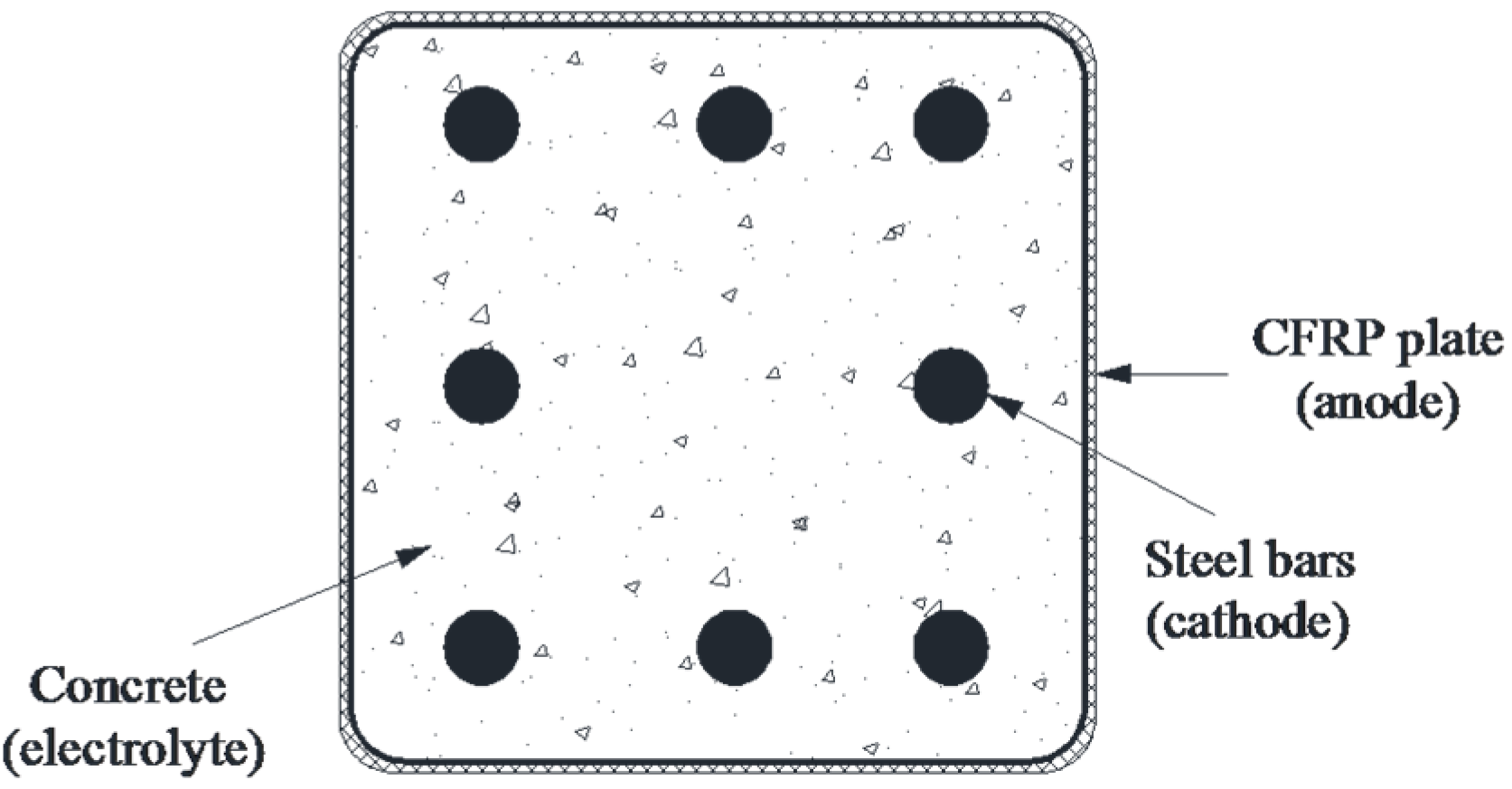
- The service life of dual-function CFRP was discussed. In three electrolyte solutions investigated, CFRP plates were demonstrated to be capable of serving as both structural strengthening and impressed anode materials in ICCP systems for reinforced concrete structures. The minimum predicted service life was 23.9 years, 24.6 years, and 23.8 years, respectively, corresponding to the NaCl solution, the NaOH solution, and the pore solution, even with the maximum acceptable protection current density and reinforcement ratios. Notably, this prediction was conservative, because the polarization data obtained was from a simulated ICCP system with an environment much worse than that in practical concrete structures.
Supplementary Files
Supplementary File 1Acknowledgments
Author Contributions
Conflicts of Interest
Notation
| As | Measured anodic surface area of test region of CFRP specimens; |
| Ac | Measured cross-sectional area of CFRP specimens; |
| fu | Ultimate tensile strength of CFRP specimens; |
| fu,I0 | Average ultimate tensile strength of CFRP specimens I0D25, I0D25#, I0D50, and I0D50#; |
| i | Current density; |
| q | Charge density—the total charge per unit area passed by the CFRP surface; |
| K | Deterioration factor; |
| KExp | Experimental deterioration factor; |
| KCal | Calculated deterioration factor; |
| V | Feeding voltage or potential; |
| ip | Protection current density; |
| n | Number of steel rebars in the concrete element; |
| Qanode | Anode’s capacity to transfer charges; |
| Qcathode | Total charge quantity past the cathode during cathodic protection; |
| QCFRP | CFRP plate’s capacity to transfer charge; |
| Qsteel | Total charge quantity past the steel in the concrete element during cathodic protection; |
| tg | Duration of impressed current; |
| tlife | Predicted service life of the ICCP system by QCFRP; |
| ρ | Reinforcement ratio. |
References
- Jing, X.; Wu, Y. Electrochemical studies on the performance of conductive overlay material in cathodic protection of reinforced concrete. Constr. Build. Mater. 2011, 25, 2655–2662. [Google Scholar] [CrossRef]
- Bertolini, L.; Bolzoni, F.; Pedeferri, P.; Lazzari, L.; Pastore, T. Cathodic protection and cathodic preventionin concrete: principles and applications. J. Appl. Electrochem. 1998, 28, 1321–1331. [Google Scholar] [CrossRef]
- Hong, D.; Fan, W.; Luo, D.; Ge, Y.; Zhu, Y. Study and application of impressed current cathodic protection technique for atmospherically exposed salt-contaminated reinforced concrete structures. ACI Mater. J. 1993, 90, 3–7. [Google Scholar]
- Pedeferri, P. Cathodic protection and cathodic prevention. Constr. Build. Mater. 1996, 10, 391–402. [Google Scholar] [CrossRef]
- Barnhart, R. FHWA position on cathodic protection systems. In Memorandum of FHWA; US Federal Highway Administration: Washington, DC, USA, 1982. [Google Scholar]
- Lambert, P.; Van Nguyen, C.; Mangat, P.S.; O’Flaherty, F.J.; Jones, G. Dual function carbon fibre fabric strengthening and impressed current cathodic protection (ICCP) anode for reinforced concrete structures. Mater. Struct. 2015, 48, 2157–2167. [Google Scholar] [CrossRef]
- Shao, Z.-G.; Zhu, F.; Lin, W.-F.; Christensen, P.A.; Zhang, H.; Yi, B. Preparation and characterization of new anodes based on Ti mesh for direct methanol fuel cells. J. Electrochem. Soc. 2006, 153, A1575–A1583. [Google Scholar] [CrossRef]
- Holcomb, G.; Bullard, S.; Covino, B., Jr.; Cramer, S.; Cryer, C.; McGill, G. Electrochemical Aging of Thermal-Sprayed Zinc Anodes on Concrete; Albany Research Center: Albany, OR, USA, 1996; pp. 185–192. [Google Scholar]
- Clemena, G.G.; Jackson, D.R. Performance of a Conductive-Paint Anode in Cathodic Protection Systems for Inland Concrete Bridge Piers in Virginia; Virginia Transportation Research Council Research Report, VTRC 98-R7; Virginia Transportation Research Council: Charlottesville, VA, USA, 1997. [Google Scholar]
- Orlikowski, J.; Cebulski, S.; Darowicki, K. Electrochemical investigations of conductive coatings applied as anodes in cathodic protection of reinforced concrete. Cement Concr. Compos. 2004, 26, 721–728. [Google Scholar] [CrossRef]
- Nguyen, C.; Mangat, P.; Lambert, P.; O’Flaherty, F.; Jones, G. Dual function carbon fibre strengthening and cathodic protection anode for reinforced concrete structures. In Concrete Repair, Rehabilitation and Retrofitting III; Taylor & Francis Group: London, UK, 2012; pp. 1179–1185. [Google Scholar]
- NACE International. Testing of Embeddable Impressed Current Anodes for Use in Cathodic Protection of Atmospherically Exposed Steel-Reinforced Concrete; NACE: Houston, TX, USA, 2007. [Google Scholar]
- O’Flaherty, F.J.; Mangat, P.S.; Lambert, P.; Browne, E.H. Effect of under-reinforcement on the flexural strength of corroded beams. Mater. Struct. 2007, 41, 311–321. [Google Scholar] [CrossRef]
- Al-Mahmoud, F.; Castel, A.; Francois, R.; Tourneur, C. Strengthening of RC members with near-surface mounted CFRP rods. Compos. Struct. 2009, 91, 138–147. [Google Scholar] [CrossRef]
- Motavalli, M.; Czaderski, C.; Pfyl-Lang, K. Prestressed CFRP for Strengthening of Reinforced Concrete Structures: Recent Developments at Empa, Switzerland. J. Compos. Constr. 2011, 15, 194–205. [Google Scholar] [CrossRef]
- Raupach, M.; Elsener, B.; Polder, R.; mietz, J. Corrosion of Reinforcement in Concrete. Mechanisms, Monitoring, Inhibitors and Rehabilitation Techniques; Woodhead Publishing Limited: Cambridge, UK, 2007. [Google Scholar]
- Lee-Orantes, F.; Torres-Acosta, A.; Martínez-Madrid, M.; López-Cajún, C. Cathodic Protection in Reinforced Concrete Elements, using Carbon Fibers Base Composites. ECS Trans. 2007, 3, 93–98. [Google Scholar]
- Nguyen, C.; Lambert, P.; Mangat, P.; O’Flaherty, F.; Jones, G. The performance of carbon fibre composite as ICCP anode for reinforced concrete structures. ISRN Corros J. 2012, 10, 814–923. [Google Scholar] [CrossRef]
- Sun, H.; Zhu, M.; Han, N.; Zhu, J.-H.; Xing, F. Corrosion behavior of carbon fiber reinforced polymer anode in simulated impressed current cathodic protection system with 3% NaCl solution. Constr. Build. Mater. 2014. subbmitted. [Google Scholar]
- Zhu, J.-H.; Guo, G.; Zhu, M.; Fang, Y.; Chen, X.; Xing, F. Mechanical and electrochemical performance of carbon fiber-reinforced polymer in oxygen evolution environment. Appl. Compos. Mater. 2015. subbmitted. [Google Scholar]
- Zhu, J.-H.; Zhu, M.; Han, N.; Liu, W.; Xing, F. Electrical and Mechanical Performance of Carbon Fiber-Reinforced Polymer Used as the Impressed Current Anode Material. Materials 2014, 7, 5438–5453. [Google Scholar] [CrossRef]
- American Society for Testing and Materials (Filadelfia). Standard Test Method for Tensile Properties of Plastics; ASTM International: West Conshohocken, PA, USA, 2010. [Google Scholar]
- American Society for Testing and Materials. Standard Test Method for Tensile Properties of Polymer Matrix Composite Materials; ASTM International: West Conshohocken, PA, USA, 2008. [Google Scholar]
- Hara, E.; Yokozeki, T.; Hatta, H.; Ishikawa, T.; Iwahori, Y. Effects of geometry and specimen size on out-of-plane tensile strength of aligned CFRP determined by direct tensile method. Compos. Part A Appl. Sci. Manuf. 2010, 41, 1425–1433. [Google Scholar] [CrossRef]
- Ueda, T.; Dai, J. Interface bond between FRP sheets and concrete substrates: properties, numerical modeling and roles in member behaviour. Prog. Struct. Eng. Mater. 2005, 7, 27–43. [Google Scholar] [CrossRef]
- Peng, H.; Wang, H.; Chen, J.; Zhang, K. Experimental Study on Bond Performance of Near-Surface-Mounted CFRP Strips-Concrete Interface. In Proceedings of the 2013 Fourth International Conference on Digital Manufacturing & Automation (ICDMA), Qing Dao, China, 29 June 2013; pp. 586–590.
- Palmieri, A.; Matthys, S.; Barros, J.A.O.; Costa, I.; Bilotta, A.; Nigro, E.; Ceroni, F.; Szambo, Z.; Balazs, G. Bond of NSM FRP strengthened concrete: round robin test initiative. In Proceedings of the 6th International Conference on FRP Composites in Civil Engineering (CICE—2012), Rome, Italy, 13–15 June 2012; pp. 1–8.
- Cruz, J.M.D.S. Bond Between Near-Surface Mounted Carbon-Fiber-Reinforced Polymer Laminate Strips and Concrete. J. Compos. Constr. 2014, 8, 519–527. [Google Scholar] [CrossRef]
© 2016 by the authors; licensee MDPI, Basel, Switzerland. This article is an open access article distributed under the terms and conditions of the Creative Commons by Attribution (CC-BY) license (http://creativecommons.org/licenses/by/4.0/).
Share and Cite
Zhu, J.-H.; Guo, G.; Wei, L.; Zhu, M.; Chen, X. Dual Function Behavior of Carbon Fiber-Reinforced Polymer in Simulated Pore Solution. Materials 2016, 9, 103. https://doi.org/10.3390/ma9020103
Zhu J-H, Guo G, Wei L, Zhu M, Chen X. Dual Function Behavior of Carbon Fiber-Reinforced Polymer in Simulated Pore Solution. Materials. 2016; 9(2):103. https://doi.org/10.3390/ma9020103
Chicago/Turabian StyleZhu, Ji-Hua, Guanping Guo, Liangliang Wei, Miaochang Zhu, and Xianchuan Chen. 2016. "Dual Function Behavior of Carbon Fiber-Reinforced Polymer in Simulated Pore Solution" Materials 9, no. 2: 103. https://doi.org/10.3390/ma9020103
APA StyleZhu, J.-H., Guo, G., Wei, L., Zhu, M., & Chen, X. (2016). Dual Function Behavior of Carbon Fiber-Reinforced Polymer in Simulated Pore Solution. Materials, 9(2), 103. https://doi.org/10.3390/ma9020103