
Improved Thin-Kerf Processing in Cf/SiC Composite by Waterjet-Guided Nanosecond Laser Decreases Oxidation and Thermal Effect


 , ,
, ,  ,
, 
Abstract
:1. Introduction
2. Materials and Methods
2.1. Material
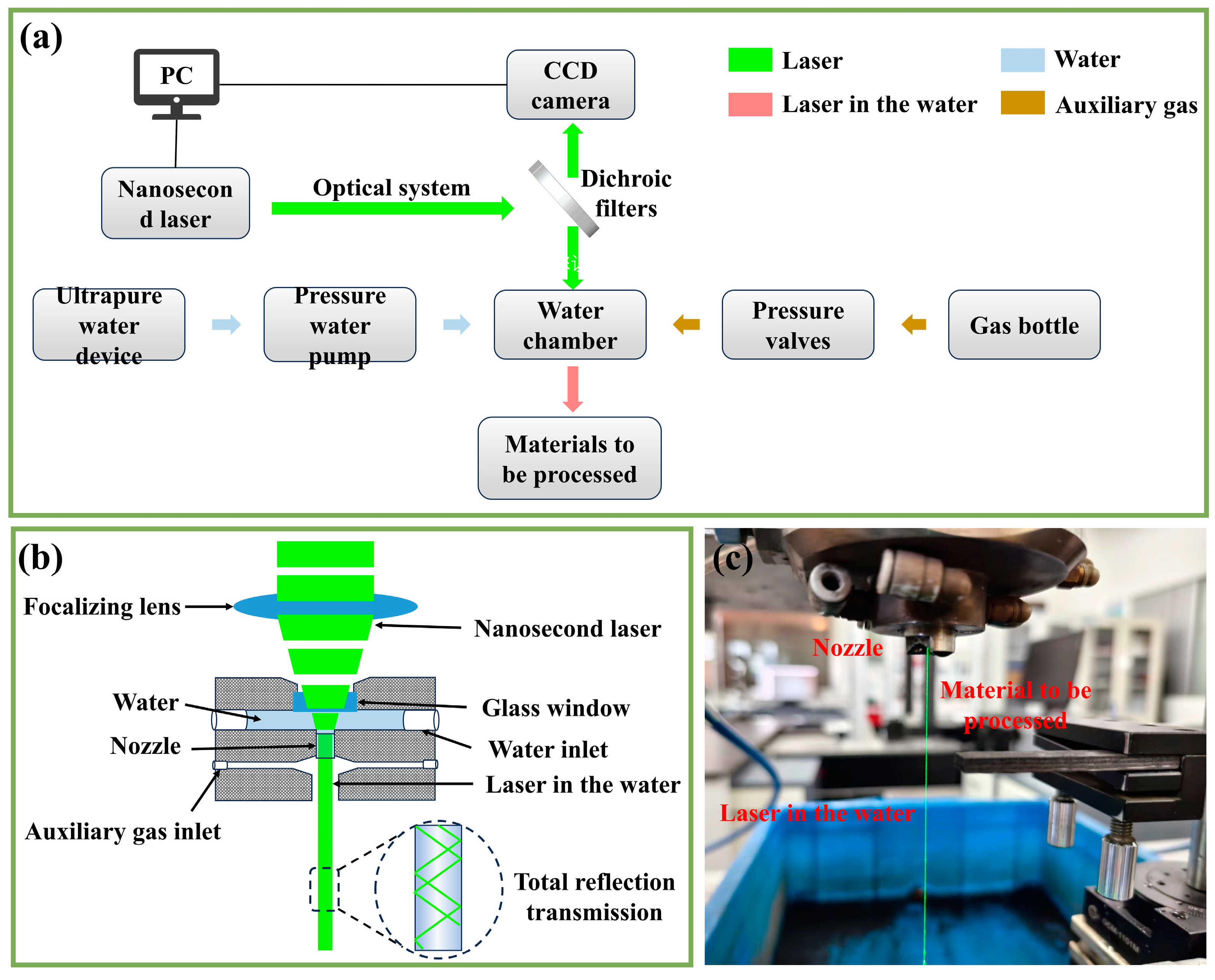
2.2. Laser Processing
2.3. Characterization
3. Results and Discussion
3.1. Morphology and Depth of Kerf by Single-Path Laser Processing
3.2. Morphology and Microstructure of Kerf by Multi-Path Laser Processing
3.3. Effect of Coupling Medium on Laser-Processed Kerf
4. Conclusions
- (1)
- The coupling of helium in the GNL mode laser processing can make full use of the laser energy, but it results in spattering in the kerf margin and a recast layer in the kerf surface, accompanied by obvious oxidation, while the coupling of the waterjet in the WNL mode laser processing decreases the oxidation significantly and removes the remelting debris, which produces a clear and flat kerf surface.
- (2)
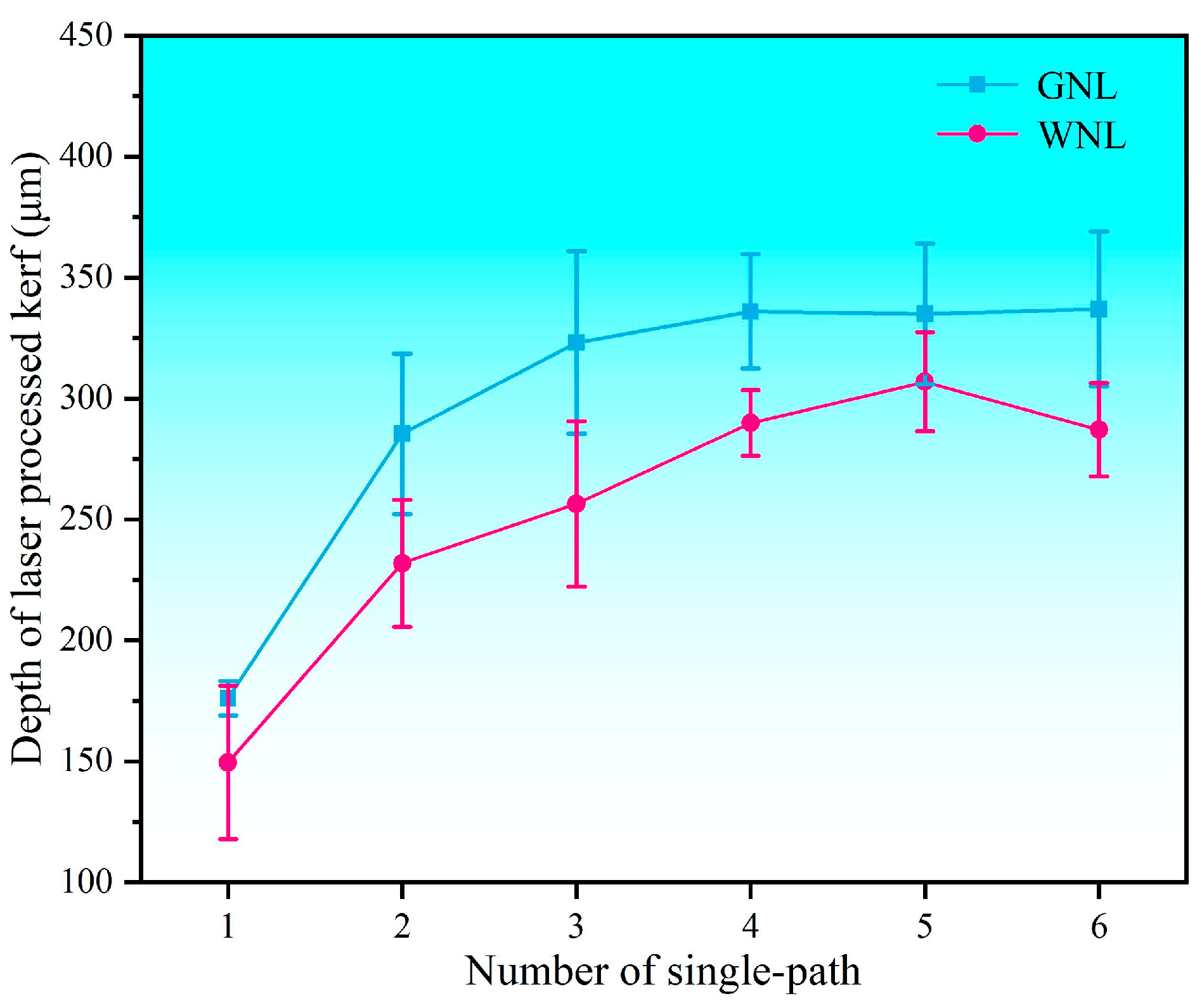
- Due to the taper caused by laser energy dissipation, the single-path laser processing in the Cf/SiC composite has a limited depth. The maximum depth of the kerf prepared by single-path laser processing with the GNL mode is about 328 μm, which can be obtained by repeating the single-path processing four times. The maximum depth of the kerf prepared by single-path laser processing with the WNL mode is about 302 μm, which can be obtained by repeating the single-path processing five times.
- (3)
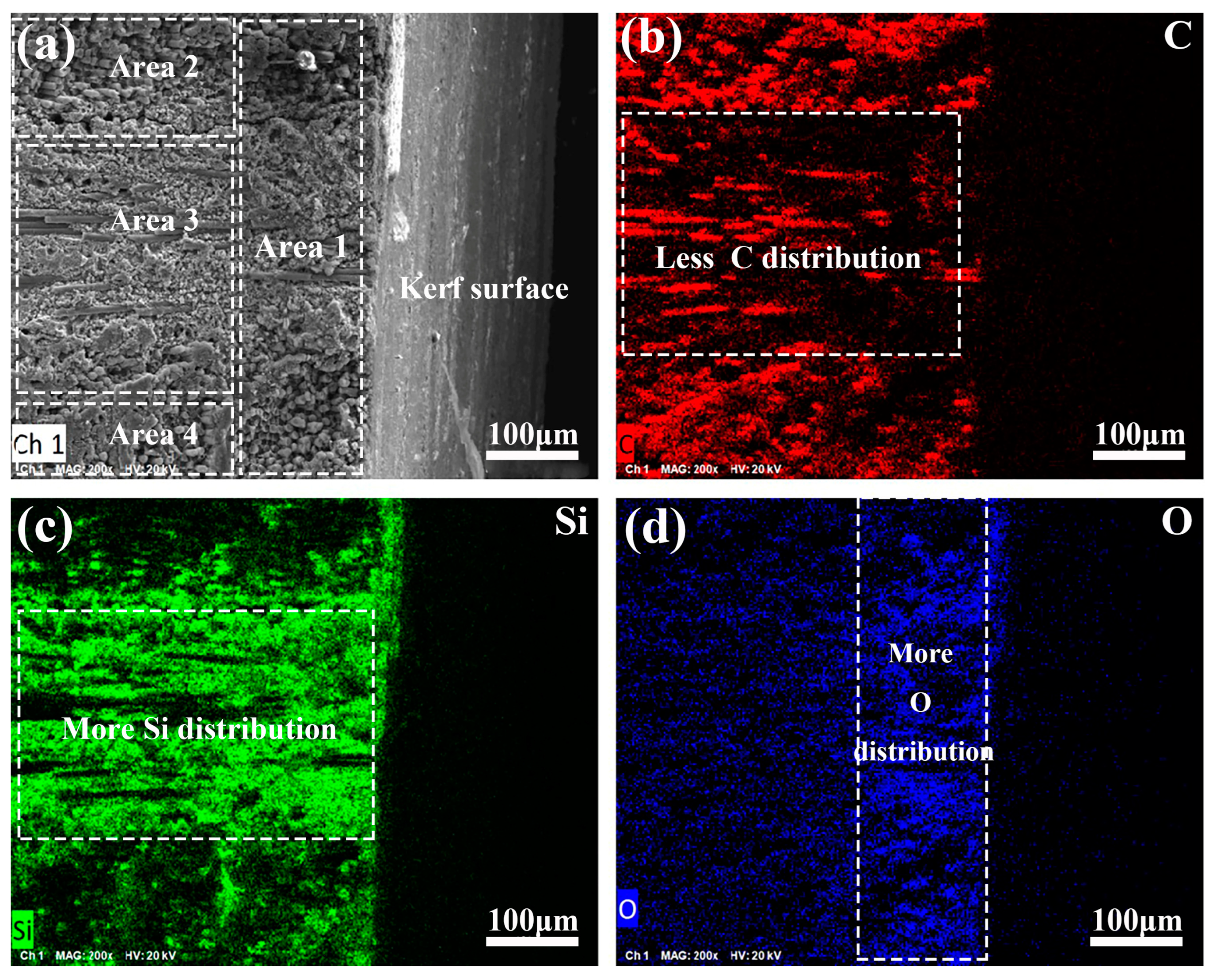
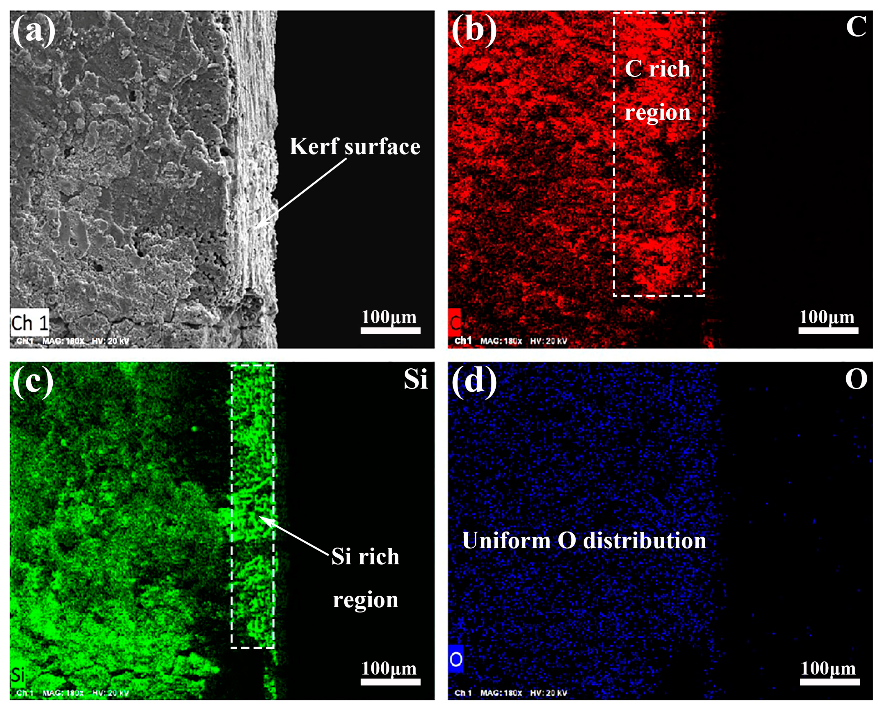
- The multi-path laser processing with the GNL and WNL modes can realize the fabrication of the through kerf in the Cf/SiC composite, but the coupling medium obviously influences the kerf surface and microstructure of the underlying region. The kerf surface prepared by the GNL mode has a varied surface morphology, which transits from the top layer, covered with oxide particles and some cracks, to the bottom layer, featured with micro-grooves and small oxides. The kerf surface prepared by the WNL mode has a consistently smooth and clean morphology, featured with broken carbon fiber and residual SiC matrix.
- (4)
- During the fabrication of the kerfs in the Cf/SiC composite, the ultra-high temperature and presence of oxygen induce inner oxidation. The slow laser energy dissipation and open environment in the GNL mode results in a larger HAZ and a relatively serious oxidation, which causes local phase transformation and microstructure degradation. The isolation condition and rapid cooling in the WNL mode decreases the HAZ and restrains the oxidation, almost keeping the original microstructure. The thicknesses of the HAZ in the GNL- and WNL-processed Cf/SiC composite are about 200 μm and 100 μm, respectively.
Author Contributions
Funding
Institutional Review Board Statement
Informed Consent Statement
Data Availability Statement
Conflicts of Interest
References
- Jiao, J.; Zou, Q.; Ye, Y.; Xu, Z.; Sheng, L. Carbon fiber reinforced thermoplastic composites and TC4 alloy laser assisted joining with the metal surface laser plastic-covered method. Compos. B Eng. 2021, 213, 108738. [Google Scholar] [CrossRef]
- Zhao, C.; Wen, M.; Wang, Q.; Ouyang, W.; Xu, D.; Jia, Z.; Zheng, Y.; Xi, T.; Sheng, L. Tailoring the corrosion resistance and biological performance of Mg-Zn-Y-Nd bioimplants with multiphasic, pore-sealed cerium-doped ceramic coatings via facile one-pot plasma electrolytic oxidation. J. Mater. Sci. Technol. 2025, 230, 60–79. [Google Scholar] [CrossRef]
- Sheng, L.; Yang, F.; Guo, J.; Xi, T.; Ye, H. Investigation on NiAl–TiC–Al2O3 composite prepared by self-propagation high temperature synthesis with hot extrusion. Compos. B Eng. 2013, 45, 785–791. [Google Scholar] [CrossRef]
- Ouyang, W.; Zhang, L.; Wu, H.; Wu, D.; Zhang, S.; Qin, X.; Jiang, S.; Li, S.; Zhang, W.; Sheng, L. Optimized mechanical properties of the hot forged Ti–6Al–4V alloy by regulating multiscale microstructure via laser shock peening. Int. J. Mach. Tool Manu. 2024, 201, 104192. [Google Scholar] [CrossRef]
- Kumar, P.; Srivastava, V. Tribological behaviour of C/C–SiC composites—A review. J. Adv. Ceram. 2016, 5, 1–12. [Google Scholar] [CrossRef]
- Wu, D.; Wang, Y.; Shang, L.; Pu, Y.; Gao, Z. Thermo-mechanical properties of C/SiC composite structure under extremely high temperature environment up to 1500 °C. Compos. B Eng. 2016, 90, 424–431. [Google Scholar] [CrossRef]
- Cai, F.; Ni, D.; Zhou, Z.; Chen, B.; Zou, X.; Gao, L.; He, P.; Ding, Y.; Zhang, X.; Dong, S. Ablation mechanism of Cf/(Ti0. 2Zr0. 2Hf0. 2Nb0. 2Ta0. 2) C-SiC composite during plasma ablation above 2000 °C. J. Mater. Sci. Technol. 2025, 213, 109–117. [Google Scholar] [CrossRef]
- Sui, T.; Bao, X.; Li, L.; He, Y.; Ning, G.; Lin, B.; Yan, S.; Ke, L. Unstable feature and tribological performance transition of Cf/C–SiC under elevated temperatures. Friction 2025. [Google Scholar] [CrossRef]
- Lu, L.; Wen, Q.; Hu, J.; Jiang, T.; Ren, X.; Wang, Y.; Zeng, Y.; Xiong, X. Single-source-precursor synthesis and air-plasma ablation behavior of (Ti, Zr, Hf) C/SiC ceramic nanocomposites at 2200 °C. J. Adv. Ceram. 2024, 13, 1043–1059. [Google Scholar] [CrossRef]
- Liu, J.; Wei, X.; Gao, L.; Tao, J.; Xu, L.; Peng, G.; Jin, H.; Wang, Y.; Yao, Z.; Zhou, J. An overview of C-SiC microwave absorption composites serving in harsh environments. J. Eur. Ceram. Soc. 2023, 43, 1237–1254. [Google Scholar] [CrossRef]
- Xu, Q.; Hou, L.; Hou, L.; Li, Z.; Ren, S.; Aboudaif, M.K.; Awwad, E.M.; Saeed, N.A. Free Vibration analysis of C/SiC blisk based on modified global mode method. Thin-Walled Struct. 2024, 204, 112285. [Google Scholar] [CrossRef]
- Zhao, G.; Jiang, Z.; Qu, Z.; Xi, H.; Ai, S. Fracture characteristics and in-situ damage mechanism of PIP-C/SiC composites to various temperatures and loading velocities. Eng. Fract. Mech. 2023, 286, 109300. [Google Scholar] [CrossRef]
- Qinglong, A.; Jie, C.; Weiwei, M.; Ming, C. Machining of SiC ceramic matrix composites: A review. Chin. J. Aeronaut. 2021, 34, 540–567. [Google Scholar] [CrossRef]
- He, Z.; Xu, H.; Sun, L.; Li, C.; Si, X.; Cao, J. Microstructure and properties of C/C and C/SiC composites brazed by reactive infiltration of SiZr filler alloy. Mater. Charact. 2024, 213, 114038. [Google Scholar] [CrossRef]
- Zhang, W.; Zhang, G.; Bao, J.; Guo, C.; Cui, C.; Zhu, W.; Xu, C.; Li, W. Preparation and mechanical properties of Cf/SiC composites via pressure-assisted gel impregnation and PIP. J. Eur. Ceram. Soc. 2024, 44, 7523–7530. [Google Scholar] [CrossRef]
- Sun, H.; Fan, S.; Wang, L.; Ma, X.; Deng, J.; Cheng, L.; Zhang, L. Microstructure and tribological properties of PIP-SiC modified C/C–SiC brake materials. Ceram. Int. 2021, 47, 15568–15579. [Google Scholar] [CrossRef]
- Xiong, C.; Li, T.; Zhao, T.; Khan, M.; Wang, J.; Ji, X.; Li, H.; Liu, W.; Shang, Y. Preparation of C/C–SiC composite by low temperature compression molding–liquid silicon infiltration and its application in automobile brake. Ceram. Int. 2016, 42, 1057–1062. [Google Scholar] [CrossRef]
- Liu, F.; Liu, S.; Zhang, Q.; Li, Z.; Qiu, H. Quantitative non-destructive evaluation of drilling defects in SiCf/SiC composites using low-energy X-ray imaging technique. NDT E Int. 2020, 116, 102364. [Google Scholar] [CrossRef]
- Ai, S.; Song, W.; Chen, Y. Stress field and damage evolution in C/SiC woven composites: Image-based finite element analysis and in situ X-ray computed tomography tests. J. Eur. Ceram. Soc. 2021, 41, 2323–2334. [Google Scholar] [CrossRef]
- Zhao, Y.; Yang, X.; Lu, Y.; Duan, X. Electrical discharge-mechanical hybrid drilling of micro-holes in carbon fibre-reinforced polymers. Int. J. Mach. Tool Manuf. 2025, 205, 104243. [Google Scholar] [CrossRef]
- Cao, X.; Lin, B.; Zhang, X. A study on grinding surface waviness of woven ceramic matrix composites. Appl. Surf. Sci. 2013, 270, 503–512. [Google Scholar] [CrossRef]
- Ramulu, M.; Jenkins, M.; Guo, Z. Abrasive water jet machining mechanisms in continuous-fiber ceramic composites. J. Compos. Technol. Res. 2001, 23, 82–91. [Google Scholar] [CrossRef]
- Cao, H.-T.; Ho, J.-R.; Tung, P.-C.; Lin, Y.-T.; Lin, C.-K. Machined quality prediction and optimization for micro-EDM drilling of semi-conductive SiC wafer. Mater. Sci. Semicond. Process. 2024, 169, 107911. [Google Scholar] [CrossRef]
- Wang, J.; Xie, W.; Yan, H.; Yu, D.; Gao, B.; Yang, F.; Liu, S.; Meng, S. Study on multi-scale ablation behavior of C/SiC composites under high-energy CW laser irradiation. J. Eur. Ceram. Soc. 2024, 44, 4524–4535. [Google Scholar] [CrossRef]
- Yan, S.; Diao, Q.; Chen, B.; Zou, H.; Ren, X.; Wang, Y.; Zhang, C.; Sui, T.; Lin, B. Nanosecond laser ablation behavior of C/SiC composites under water layer protection: Experiments and theoretical investigation. Opt. Laser Technol. 2024, 172, 110516. [Google Scholar] [CrossRef]
- Yuan, C.; Wang, B.; Wang, J.; Wang, Y.; Sheng, L.; Jiao, J.; Yao, J.; Huang, Y.; Zhang, W. Effects of incidence angle and optimization in femtosecond laser polishing of C/SiC composites. Ceram. Int. 2022, 48, 32290–32304. [Google Scholar] [CrossRef]
- Zhang, Y.; Liu, Y.; Cao, L.; Chen, J.; Qiu, G.; Wang, J. Preparation and analysis of micro-holes in C/SiC composites and ablation with a continuous wave laser. J. Eur. Ceram. Soc. 2021, 41, 176–184. [Google Scholar] [CrossRef]
- Hu, T.; Yuan, S.; Wei, J.; Zhou, N.; Zhang, Z.; Zhang, J.; Li, X. Water jet guided laser grooving of SiCf/SiC ceramic matrix composites. Opt. Laser Technol. 2024, 168, 109991. [Google Scholar] [CrossRef]
- Sheng, L.-Y.; Fang, Y.; Xi, T.-F.; Zheng, Y.-F.; Guo, J.-T. Microstructure and room temperature mechanical properties of NiAl–Cr (Mo)–(Hf, Dy) hypoeutectic alloy prepared by injection casting. Trans. Nonferr. Metal. Soc. 2013, 23, 983–990. [Google Scholar] [CrossRef]
- Jiao, H.; Zhang, G.; Huang, P.; Lu, C.; Huang, Y.; Zhou, J.; Long, Y. A multiphase flow model simulation of water jet-guided laser drilling in 304 stainless steel. J. Manuf. Process. 2024, 120, 170–191. [Google Scholar] [CrossRef]
- Wang, S.; Ding, Y.; Li, Y.; Ge, C.; Xie, W.; Huo, H.; Yang, L.; Zhang, W.; Lu, Y. Investigations on the water-jet guided laser scribing of thermal barrier coated IC21 nickel-based superalloy. Opt. Laser Technol. 2024, 170, 110155. [Google Scholar] [CrossRef]
- Wu, Y.; Zhang, G.; Wang, J.; Chao, Y.; Zhang, W. The cutting process and damage mechanism of large thickness CFRP based on water jet guided laser processing. Opt. Laser Technol. 2021, 141, 107140. [Google Scholar] [CrossRef]
- Shi, Y.; Jiang, Z.; Cao, J.; Ehmann, K.F. Texturing of metallic surfaces for superhydrophobicity by water jet guided laser micro-machining. Appl. Surf. Sci. 2020, 500, 144286. [Google Scholar] [CrossRef]
- Chao, Y.; Liu, Y.; Xu, Z.; Xie, W.; Zhang, L.; Ouyang, W.; Wu, H.; Pan, Z.; Jiao, J.; Li, S.; et al. Improving superficial microstructure and properties of the laser-processed ultrathin kerf in Ti-6Al-4V alloy by water-jet guiding. J. Mater. Sci. Technol. 2023, 156, 32–53. [Google Scholar] [CrossRef]
- Sun, D.; Han, F.; Ying, W. The experimental investigation of water jet–guided laser cutting of CFRP. Int. J. Adv. Manuf. Technol. 2019, 102, 719–729. [Google Scholar] [CrossRef]
- Xia, K.; Yang, H.; Ren, N.; Di, J.; Han, Q. Effects of water temperature on femtosecond laser layered-ring trepanning in superalloy with water-based assistance. Opt. Laser Technol. 2024, 170, 110311. [Google Scholar] [CrossRef]
- Zhang, G.; Wu, Y.; Chao, Y.; Zhang, T.; Wang, J.; Zhang, W. Simulation and experimental investigation on energy distribution of water column in waterjet guided laser processing. In Proceedings of the 24th National Laser Conference & Fifteenth National Conference on Laser Technology and Optoelectronics, Shanghai, China, 17–20 October 2020; pp. 862–867. [Google Scholar]
- Sheng, L.; Cheng, X.; Jiang, S.; Zhao, C.; Liu, J.; Jing, C.; Wang, J.; Xu, L.; Xiao, Y.; Wang, B.; et al. Investigation on cutting of CFRP composite by nanosecond short-pulsed laser with rotary drilling method. Sci. Eng. Compos. Mater. 2025, 32, 20240047. [Google Scholar] [CrossRef]
- Li, M.; Wen, Z.-X.; Wang, P.; Liu, Y.-X.; Li, Z.-W.; Yue, Z.-F. Femtosecond laser high-quality drilling of film cooling holes in nickel-based single superalloy for turbine blades with a two-step helical drilling method. J. Mater. Process. Technol. 2023, 312, 117827. [Google Scholar] [CrossRef]
- Sheng, L.; Zhao, H. Investigation of Al-Si-Cu-Zn-Y-base alloy powders prepared by ultrasonic gas atomization for brazing of an Al-base alloy. Strength Mater. 2021, 53, 591–600. [Google Scholar] [CrossRef]
- Sheng, L.Y.; Guo, J.T.; Xi, T.F.; Zhang, B.; Ye, H.Q. ZrO2 strengthened NiAl/Cr (Mo, Hf) composite fabricated by powder metallurgy. Prog. Nat. Sci. Mater. 2012, 22, 231–236. [Google Scholar] [CrossRef]
- Tang, S.; Deng, J.; Wang, S.; Liu, W. Comparison of thermal and ablation behaviors of C/SiC composites and C/ZrB2–SiC composites. Corros. Sci. 2009, 51, 54–61. [Google Scholar] [CrossRef]
- Wei, J.; Zhou, N.; Gao, M.; Hu, T.; Li, X.; Zhang, J.; An, W.; Zhang, W.; Yuan, S.; Guo, F. Laser a blation of SiC/SiC ceramic matrix composites: Morphological characterization, component evolution and oxidation mechanisms. Corros. Sci. 2024, 227, 111762. [Google Scholar] [CrossRef]
- Wei, J.; Yuan, S.; Yang, S.; Gao, M.; Fu, Y.; Hu, T.; Li, X.; Fan, X.; Zhang, W. Waterjet-guided laser processing of SiC/SiC ceramic matrix composites to obtain high cleanliness and low oxidation damage characteristics surfaces. Surf. Coat. Technol. 2024, 484, 130791. [Google Scholar] [CrossRef]
- Zhang, G.; Wang, J.; Chen, Z.; Wu, Y.; Bao, B.; Zhang, W. An optical field regulation method for waterjet-guided laser: Reducing taper and improving deep-processing capability. J. Mater. Process. Technol. 2024, 334, 118637. [Google Scholar] [CrossRef]
- Sheng, L.; Yang, F.; Xi, T.; Lai, C.; Ye, H. Influence of heat treatment on interface of Cu/Al bimetal composite fabricated by cold rolling. Compos. B Eng. 2011, 42, 1468–1473. [Google Scholar] [CrossRef]
- Zhao, C.; Cheng, J.; Zhang, L.; Ouyang, W.; Sheng, L. Effect of rotating laser welding on microstructure and mechanical properties of Ti6Al4V alloy butt-welded joint. J. Mater. Sci. 2025, 60, 4864–4882. [Google Scholar] [CrossRef]
- Li, X.; Zhang, G.; Tronstad, R.; Ostrovski, O. Reduction of quartz to silicon monoxide by methane-hydrogen mixtures. Metall. Mater. Trans. B 2016, 47, 2197–2204. [Google Scholar] [CrossRef]
- Koutsoyiannis, D. Clausius–Clapeyron equation and saturation vapour pressure: Simple theory reconciled with practice. Eur. J. Phys. 2012, 33, 295. [Google Scholar] [CrossRef]
- Sheng, L.; Xiao, Y.; Jiao, C.; Li, Y.; Wu, Z.; Shao, L. Influence of layer number on microstructure, mechanical properties and wear behavior of the TiN/Ti multilayer coatings fabricated by high-power magnetron sputtering deposition. J. Manuf. Process 2021, 70, 529–542. [Google Scholar] [CrossRef]
- Nian, Z.; Zhao, G.; Xin, L.; Yang, H.; Li, L. Laser-induced oxidation of Cf/SiC composites: Oxidation behavior analysis and parameter optimization. Ceram. Int. 2024, 50, 33445–33454. [Google Scholar] [CrossRef]
- Ouyang, W.; Xu, Z.; Chao, Y.; Liu, Y.; Luo, W.; Jiao, J.; Sheng, L.; Zhang, W. Effect of electrostatic field on microstructure and mechanical properties of the 316L stainless steel modified layer fabricated by laser cladding. Mater. Charact. 2022, 191, 112123. [Google Scholar] [CrossRef]
- Zhao, H.; Zhao, C.; Xie, W.; Wu, D.; Du, B.; Zhang, X.; Wen, M.; Ma, R.; Li, R.; Jiao, J.; et al. Research Progress of Laser Cladding on the Surface of Titanium and Its Alloys. Materials 2023, 16, 3250. [Google Scholar] [CrossRef] [PubMed]
- Ouyang, W.; Jiao, J.; Xu, Z.; Xia, H.; Ye, Y.; Zou, Q.; Tian, R.; Sheng, L. Experimental study on CFRP drilling with the picosecond laser “double rotatio” cutting technique. Opt. Laser Technol. 2021, 142, 107238. [Google Scholar] [CrossRef]
- Zhang, X.; Luo, X.; Yang, X.; Zheng, L.; Liu, Z.; Huang, Q. Ablative property and mechanism of pitch-based carbon fiber modified C/C composites with high thermal conductivity. Ceram. Int. 2024, 50, 52967–52980. [Google Scholar] [CrossRef]
- Wang, P.; Zhang, Z.; Hao, B.; Wei, S.; Huang, Y.; Zhang, G. Investigation on heat transfer and ablation mechanism of CFRP by different laser scanning directions. Compos. B Eng. 2023, 262, 110827. [Google Scholar] [CrossRef]


| Diameter of Carbon Fiber (μm) | Thickness of Pyrolytic Carbon Interface Layer (nm) | Carbon Fiber Volume Fraction (%) | Density (g/cm3) | Porosity (%) |
|---|---|---|---|---|
| 6~8 | ~300 | ~40 | 1.7 | ~18 |
| Waterjet Velocity (m/s) | Helium Pressure (MPa) | Nozzle Diameter (μm) | Scanning Speed (mm/s) | Laser Spot Diameter (μm) | Distance Between Parallel Paths (μm) |
|---|---|---|---|---|---|
| 110 | 0.2 | 100 | 3 | 30 | 70 |
| Reaction | (KJ/mol) |
|---|---|
| −9.073 | |
| −11.303 | |
| −9.56 | |
| −7.56 |
| Laser Processing Mode | GNL | WNL |
|---|---|---|
| Taper | Relatively high | Relatively small |
| Recast | Obvious and thick | Not visible |
| Oxidation | A great amount | Small ratio |
| HAZ | About 200 μm | Less than 100 μm |
Disclaimer/Publisher’s Note: The statements, opinions and data contained in all publications are solely those of the individual author(s) and contributor(s) and not of MDPI and/or the editor(s). MDPI and/or the editor(s) disclaim responsibility for any injury to people or property resulting from any ideas, methods, instructions or products referred to in the content. |
© 2025 by the authors. Licensee MDPI, Basel, Switzerland. This article is an open access article distributed under the terms and conditions of the Creative Commons Attribution (CC BY) license (https://creativecommons.org/licenses/by/4.0/).
Share and Cite
Wang, J.; Zhang, G.; Wang, Q.; Rong, Y.; Zhao, C.; Chen, C.; Bao, B.; Zhang, W.; Sheng, L. Improved Thin-Kerf Processing in Cf/SiC Composite by Waterjet-Guided Nanosecond Laser Decreases Oxidation and Thermal Effect. Materials 2025, 18, 1560. https://doi.org/10.3390/ma18071560
Wang J, Zhang G, Wang Q, Rong Y, Zhao C, Chen C, Bao B, Zhang W, Sheng L. Improved Thin-Kerf Processing in Cf/SiC Composite by Waterjet-Guided Nanosecond Laser Decreases Oxidation and Thermal Effect. Materials. 2025; 18(7):1560. https://doi.org/10.3390/ma18071560
Chicago/Turabian StyleWang, Jiayu, Guangyi Zhang, Qiaoli Wang, Youmin Rong, Chaochao Zhao, Chunguang Chen, Binying Bao, Wenwu Zhang, and Liyuan Sheng. 2025. "Improved Thin-Kerf Processing in Cf/SiC Composite by Waterjet-Guided Nanosecond Laser Decreases Oxidation and Thermal Effect" Materials 18, no. 7: 1560. https://doi.org/10.3390/ma18071560
APA StyleWang, J., Zhang, G., Wang, Q., Rong, Y., Zhao, C., Chen, C., Bao, B., Zhang, W., & Sheng, L. (2025). Improved Thin-Kerf Processing in Cf/SiC Composite by Waterjet-Guided Nanosecond Laser Decreases Oxidation and Thermal Effect. Materials, 18(7), 1560. https://doi.org/10.3390/ma18071560