Article

The Technological, Economic, and Strength Aspects of High-Frequency Buried Arc Welding Using the GMAW Rapid HF Process

1
Department of Technology and Automation, Faculty of Mechanical Engineering, Czestochowa University of Technology, 21 Armii Krajowej Ave., 42-200 Czestochowa, Poland
2
Department of Materials Engineering, Faculty of Production Engineering and Materials Technology, Czestochowa University of Technology, 19 Armii Krajowej Ave., 42-200 Czestochowa, Poland
*
Authors to whom correspondence should be addressed.
Materials 2025, 18(7), 1490; https://doi.org/10.3390/ma18071490
Submission received: 6 February 2025 / Revised: 27 February 2025 / Accepted: 7 March 2025 / Published: 26 March 2025
(This article belongs to the Special Issue Advances in the Welding of Materials)

Abstract

:
One of the prospective methods of robotic welding with a consumable electrode in shield gas metal arc welding is the GMAW Rapid HF process (GRHF, HF-high frequency), in which welded joints with deep penetration welds are obtained thanks to the specially programmed welding characteristics of the arc. A pulsed frequency equalized to 5000 Hz was used to achieve consumable electrode arc stabilization and improve penetration. This work consists of two main sections, including the research and analysis of wire electrode melting and weld pool formation in the innovative GRHF process and its influences on joint strength and the economic advantages of welding. As a result of our research and strength tests, as well as an image analysis of phenomena occurring in the welding arc and weld pool, assumptions were developed about the use of the GRHF process, which is characterized by deep penetration welds without welding imperfections that reduce the quality of the welded joints and their strength. Welding conditions and parameters leading to welded joints characterized by high relative strength related to the weight of the used filler material were proposed. As a result of our research, it was found that the use of welding processes with deep penetration leads to material savings related to the reduced consumption of filler materials while maintaining the required high strength of welded joints. Savings of filler materials reaching 80% were achieved compared with hitherto used methods. At the same time, the maximum load-carrying capacity of welding joints was maintained.

1. Introduction

Welded constructions usually consist of joints made with the application of two kinds of welds: fillet welds, the total percentage of which of the total number of the constructions in question may reach as high as 90%, and also butt welds. The proportions of welds are determined by the low level of difficulty of making fillet welds, by the absence of the necessity of chamfering materials to be joined, by the lower required qualifications of welders, and also by the dominating proportion of the mutually perpendicular arrangements of sheets and sections for obtaining latticed, openwork, or crate-like shapes in a construction.
Owing to robotization, welding is conducted virtually exclusively in the Flat Position, or, alternatively, in the Horizontal Position, which, in turn, makes it possible to apply higher parameters of current and voltage, meaning that welds penetrate deeply. In this manner, the assets of welding result from the possibility of avoiding the chamfering of even the thick elements of angular joints, T-joints, and cruciform ones in order to obtain butt or butt–fillet welds, approved for use by virtue of the Eurocode 3 standard [1]. These possibilities are a result of the application of the new variants of the GMAW process within the scope of highly efficient welding without the rotation of the welding arc, and this means a deep penetration buried welding arc can be obtained, which is a method located between classic welding in the shield of shielding gases with the application of the GMAW Conventional CV (GCCV, CV—Constant Voltage) method and a hybrid Laser–GMAW or Plasma–GMAW. In order to obtain stable burning conditions for a buried welding arc, it is required to apply special-purpose welding devices, guaranteeing that the voltage of a welding arc is controlled [2], or, alternatively, devices with an adjustable power source dynamic response before and after a short–circuit [3]. A different method for the stabilization of a buried welding arc is replacing a direct current on the power circuit with a unidirectional modulated one, with a frequency between 200 and 600 Hz, to concentrate the welding arc and increase penetration [4].
A solution that may become achievable in the future is the one presented in this work, consisting of the process of GMAW Rapid HF (Figure 1), in which a special-purpose programmed high-frequency source of electricity is applied in order to obtain the increasing power density of the heat source, bringing about deep penetration into a basic material. An important asset of the application of a welding arc of high frequency in comparison with different solutions is the significant reduction in the values of the welding current (to approximately 300 A) in cases where the welding arc is buried, and the transport of metal is stable. The application of high frequencies (exceeding 1000 Hz) decreases the sensitivity of the process to the disturbances of the work of a welding arc, in particular, in the case of the reduced value of the welding current without it being indispensable to apply an additional voltage control, preventing the unwelcome rotation of the welding arc. The frequency value (5000 Hz) was derived from the literature on the maximum pressure of the high-frequency arc (with an improved penetration capacity) and the metal transfer stability obtained in this study.
In similar solutions [5], in order to obtain a stable buried welding arc, higher values of welding current (approximately 600 A) are applied; alternatively, controlling that can also take advantage of a system based on additional voltage control [2,5]. The system proposed by Baba et al. [2], however, is based on welding within the scope of a comparatively low frequency of pulsation (approximately 100 Hz), which, in the case of welding currents within the scope of 400–500 A, brings about the porosity of welds, which results, among other factors, from disturbances in the transport of the metal to a welding pool.
The available literature does not provide detailed information related to the properties of joints made with the application of the GRHF process and the advantages that are possible to be achieved when taking advantage of a buried welding arc, bringing about obtaining deeply penetrated welds of high quality while simultaneously restricting the use of filler materials, bringing about a shortened arcing time, and, ipso facto, reduced electricity consumption.
When applying deep penetration methods, it is possible to obtain (T-joint welds, cruciform welds, and different angular ones), instead of fillet welds, butt–fillet or butt ones, which decreases the volume and mass of construction, the consumption of filler metals, and also the size of angular welding distortions (owing to the advantageous relocation of the centers of gravity of welds in the area adjacent to the axis of the elements being joined), which is presented in Figure 2. As a result, it brings about constructions of higher classes.
By using deep penetration methods of welding, it is possible to increase the effective throat of fillet welds (Figure 3), and, for this very reason, in accordance with the Eurocode 3 [1], while determining the calculated load-bearing cross-section capacity of fillet welds with deep material penetration, it is possible to take under consideration the additional throat of welds if the required depth of penetration may be regularly obtained (under the condition that this fact is documented). A similar approach to determining the effective throat of fillet welds with deep penetration is considered using different standards and legal regulations [6,7,8], which is presented in [9].
For several years, the most frequently made mistake has been that constructors commonly applied fillet welds with the following maximum values of throat: in the case of fillet welds made from both sides, a = 0.5t, or a = 0.7tmin in the case of one-sided ones. What is not taken into consideration is the depth of penetration on dimensioning fillet welds and treating them as if they were the butt–fillet or butt ones.
Making oneself acquainted with the solutions of contemporary welded constructions, one may conclude that the fillet welds applied to them are not designed (nor are they situated) with attention paid to individual needs, but instead designed and made without considering the actual requirements of construction and strength.
Nevertheless, the appropriate understanding of the impact of welds on construction may decrease their cost and reduce the final state of stresses and deformations, improving the properties in terms of the quality of workmanship, strength, and structural safety of the welded construction.
Because the volume of fillet welds increases in proportion to the square of its throat, whereas the strength is solely in proportion to the throat of fillet welds, and, therefore, increases much more slowly (Figure 4), the application of a large fillet weld size is not profitable, unlike inserting a weld inside the materials being joined, which achieves an increased effective throat, ipso facto the load-bearing cross-section of weld. For deeply penetrated welds, it does not excessively increase the volume and weight of construction, and the consumption of filler metals and the time of welding may be significantly reduced, whereas a simultaneous increase in strength is observed.
Following the assumptions presented in Figure 4, it is possible to observe that the volume of a fillet weld (Vw), in comparison with its length (l), increases significantly more rapidly than its strength, whereas the load-carrying capacity of a butt weld is in proportion to the thickness of elements being joined.
It ought to be simultaneously ascertained that, in the case of the same throat of a fillet weld (a), the smallest field of cross-section, and, therefore, also its volume (respectively, Aw = a2 and Vw = a2l) are obtained for a flat fillet weld with equal legs. The larger the asymmetry of the welds and the larger the size, the more filler metal is used [11]. Similar losses are found to occur when the throat of fillet welds is excessive or when, while dimensions of a weld were being established, its actual penetration on a base material was not considered. This is accompanied by an increase in the unwanted deformations of a construction resulting from the formation of the concentration of stresses and the consequent development of cracks [12,13,14,15,16].
Modern welded constructions are designed with the application of critical states of load-bearing cross-section capacity [1], which means causing a more significant effort of crucial nodes and construction elements at a level approximately as high as their yield points. The stress concentration may bring about an excess in the load-bearing cross-section capacity, change in the static system of forces, and, in the further course, the initiation and development of cracks originating from the root and spreading toward the face of the welds [17]. The lack of joint penetration on the root of a weld may become a crucial point of the entire construction, particularly when it is exposed to the impact of changing stresses originated by external loads. For this very reason, a basic principle ought to be making deeply penetrated welds free of external geometrical notches and the lack of joint penetration exerting an influence on radical deterioration within the scope of mechanical properties, which is confirmed by numerous studies [18,19,20,21].
The application of methods involving deep penetration may lead to the elimination of a critical part of those welds, especially the notches at the root (Figure 5), by achieving penetration on a previously made weld on welded joints on both sides or by making a one-side weld with complete joint penetration on both T-joints and cruciform ones.

2. Materials and Methods

In this work, a high-frequency pulsation current (5000 Hz) was applied to obtain a buried welding arc, bringing about a simultaneous shortening and concentration of a welding arc, increasing, ipso facto, the power density of the heat source. The advantage resulting from increasing the frequency of the pulsation of a welding arc is a simultaneous increase in pressure, which is exerted by it on a welding pool, bringing about its deepening and burying of a welding arc, bringing about the formation of a deep penetration and, simultaneously, avoiding the rotation of a welding arc—in turn, bringing about disturbances in the metal transfer and also undercuts.
To conduct the welding process, a synchronously connected high-frequency welding power Cloos Qineo Pulse 601 Pro (Carl Cloos Schweißtechnik GmbH, Haiger, Germany) and ESS Transtig 2704 (ESS Welding GmbH& Co. KG, Bad Waldsee, Germany), as well as a welding robot Cloos Qirox QRC 290 (Carl Cloos Schweißtechnik GmbH, Haiger, Germany), were applied. The power supply can achieve high-frequency pulsed current output with a frequency of up to 20 kHz. The recording of the time of current and voltage of a welding arc was made with the use NI USB-6251 (National Instruments, Austin, TX, USA), and 16 Channel DAQ Board (Photron Limited, San Diego, CA, USA) was synchronized with imaging space between electrodes and welding pools; it was achieved with the application of the measurement system presented in Figure 6. The arc phenomenon and molten pool formation were observed with high-speed cameras: PHOTRON 1024 PCI (Photron USA, San Diego, CA, USA) and PHANTOM VEO 710S (Vision Research, Wayne, MI, USA) with Sigma DG Macro 105 macro lens (Sigma GmbH, Rodermark, Germany). The frequency of recording the image was 10,000 frames per second, and the frequency of recording the current and voltage was 500,000 Hz.
The weld microstructure was observed by polishing the cut cross-section and then etching it with a 5% concentration of Nital solution for 5 s. The weld cross-sections were captured using Keyence VHX 7000 digital microscope (Keyence International, Osaka, Japan). VEB Fritz Heckert EU 100 tensile equipment (VEB FritzHeckert, Chemnitz, Germany) with maximum tensile force of 1000 kN) was used to test tensile strength according to ISO 9018:2016-01 [22].
The research was conducted for five kinds of steel: S355J2, S460NL, S700MC, S690QL, and 450HBW (Hardox), with thicknesses of, respectively, 8 + 8 mm (60 T joints TJ), 8 + 8 + 8 mm (60 cruciform joints CJ), 12 + 12 mm (60 TJ) 12 + 12 + 12 mm (60 CJ), 20 + 20 mm (60 TJ), and 20 + 20 + 20 mm (60 CJ). Filler metals were welding wires of the following kinds: G4Si1 and G69. The chemical composition of the welding wires and parent materials (mean value from Material Certificate for 8, 12, and 20 mm thickness base materials) is presented in Table 1. Welding conditions for joints shown in Section 3.3. are presented in Table 2.

3. Results and Discussion

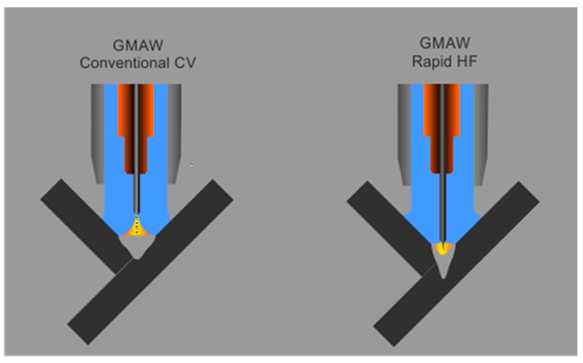
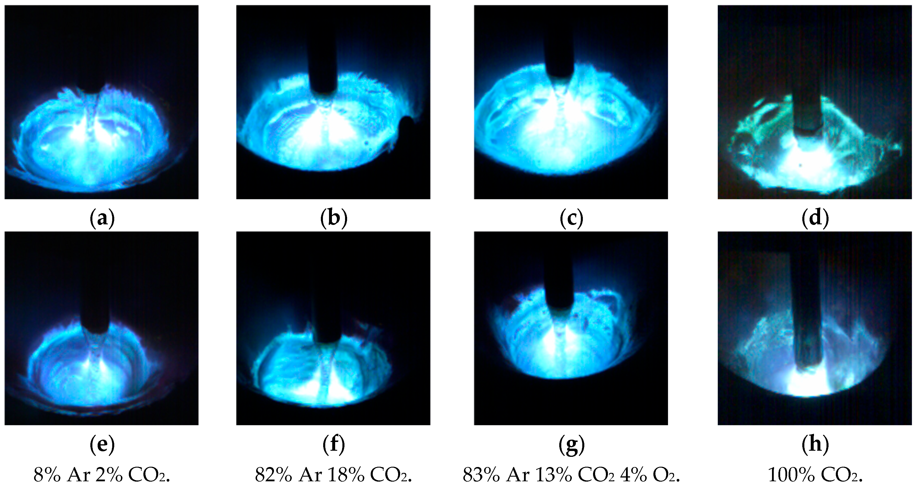
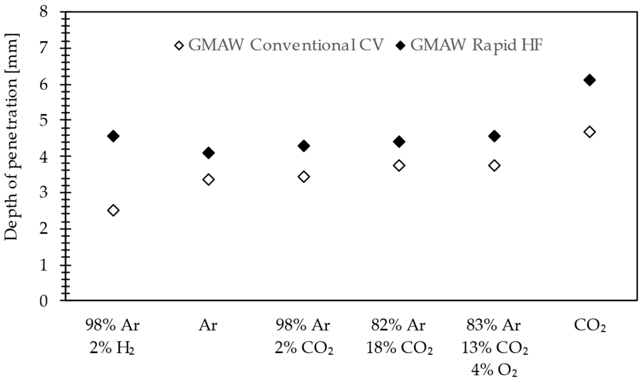
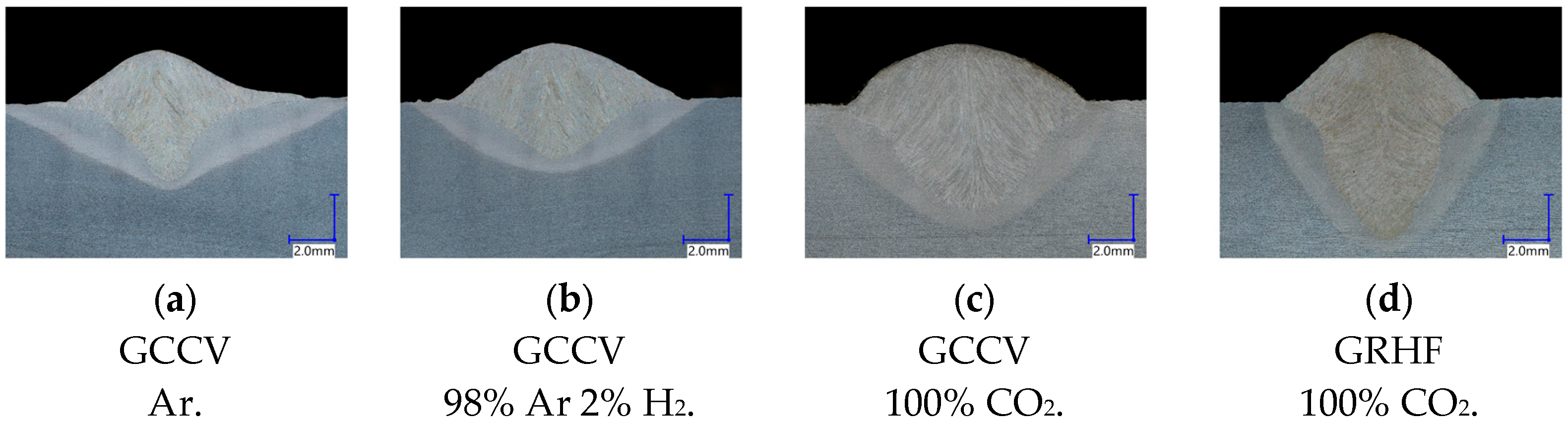
3.1. Effect of the Impact of a High-Frequency Pulsation on the Weld Pool and Penetration on the Base Material

In Figure 7, the waveforms of current and voltage obtained using the GCCV process and the GRHF are presented. The parameters are collated in Table 3. The waveforms of the current and voltage for the GCCV process are characterized by a slight ripple (Figure 7c), resulting from the dynamic performance of power supplies and transistor used in controlled inverter, as well as the value of the inductance coil of the output filter, which restrics the ripples occurring in an output voltage and current waveforms. The obtained wave of pulse for the GRHF welding arc is the result obtained by the impulse mode of the welding source, which conducts programing and sets, for a given time, the flow of electricity determined by the following parameters (Figure 8): the pulse peak current Ii, the pulse time ti, the frequency of pulsing fi, the base current Ib, and the rising rates of the pulsed current dI·dt−1. The shape of the pulse is equivalent to a triangle wave.
The obtained characteristic waveforms of current and voltage results from the high frequency, in the case of which the time of the flow of the impulse amplitudes and base current is minimal. The principal role of the programmed high-frequency is stabilizing the burning of a buried welding arc and the axially controlled flow of liquid metal from the end of the electrode to the weld pool.
The value of a base current was assumed to be higher by approximately 40 A than the values of a critical current, in the case of which the form of the transport of metal is changed from globular to spraying for a typical shielding gas applied for welding structural steels of 82% Ar 18% CO2. Because the ionization of a welding arc and its concentration are strongly connected with the applied shielding gas, for that very reason, the scope of research was broadened by adding the analysis of the impact of the types of shield gas on forming a “keyhole” and the stabilization of a liquid transport of metal. In gases in which the principal ingredient is Ar, the applied impulse wave stabilizes the streaming transfer of metal. In the case of a gas shield of 100% CO2, the application of a pulsation of high frequency brings about a smaller visible dispersion of a metal vapor plasma under the wire tip. It also increases electrical conductivity and decreases the welding arc voltage, but the tapper formation leading to streaming transfer is not observed. Applying a high-frequency pulsation current with the value of 5000 Hz brings about a shortened welding arc, narrows the taper of the arc column, and creates a weld pool on a broad scope of the applied shielding gases, which is presented in Figure 9.
The value of the force with which a welding arc impacts a liquid pool is dependent on the square of the value of a current and also on the cross-section of the arc column, which is expressed by the following equation [26,27]:
F arc = μ 0 · I 2 4 · π 2 · R 2
where μ₀ is the magnetic permeability of the vacuum, I is the current, and R is the radius of a welding arc.
The principal expected effect of the application of high-frequency pulsation (exceeding 1000 Hz) will, therefore, be an indirect increase in the pressure on the welding arc [28], brought by about an increase in the temporary value of the current to approximately 380 A (the parameters of welding are shown in Table 3), as well as a decrease in the cross-section of an arc column and a direct increase in the depth of penetration in comparison with the GCCV process having the identical mean value of the welding current and voltage of the welding arc, which is also indicated by Krivtsun et al. [29]. In [28], it is shown how the pressure of the arc (and improvable penetration capacity) changes with the pulse frequency; up to about 5 kHz, it increases rapidly and above this value, it stabilizes at approximately four times the conventional DC value. Given these results, frequencies of 5 kHz were thought to be appropriate for welding application. The high frequency used in the tests determined the shortening of the pulse duration while the arc constriction minimized the current pulse time in the amplitude phase. The arc constriction was confirmed by phenomenology using high-speed photography as well as other works [30]. Periodic expansion and arc constriction are related to the current pulsation. If the duration of the maximum value (amplitude) is shortened, the cross-section of the arc column will also decrease at the peak current, leading to an increase in power density and, as a result, increased penetration. The increase in power density results from the current flowing through the arc column with a smaller cross-section.
The effect of the increasing penetration depth in the GRHF process can be observed regardless of the composition of the applied shielding gases. Figure 10 presents the effects of a high-frequency pulsed current compared with GCCV under different shielding gases. Beads on the plate were produced on unalloyed steel S355 J2 plates (200 × 200 × 10 mm) with the standard welding conditions of a wire speed rate of 11 m·min−1, welding speed of 75 cm·min−1, and CTWD (Contact Tip to Workpiece Distance) of 16 mm. The pulsed conditions are presented in Table 3. With the Ar-H2 shielding gas for GCCV the depth of penetration is smaller than pure argon because the thermal conductivity is significantly different for these gases. In the results of Ar-H2 shielding, the shape of penetration is bowl-shaped (Figure 11b) compared with the fingerlike penetration of the Ar-shielded welding arc (Figure 11a). The depth of penetration increases with an increase in the activated gas content. Welds produced under pure CO2 are relatively narrow and deeper, as presented in Figure 11c,d. These advantages are why this gas is widely used in the Japanese industry [31]. Increasing the CO2 (O2) content in the shielding gas makes penetration and fusion area larger, especially for content higher than 30% CO2. This phenomenon is attributed in the current literature [32] to a higher heat conductivity of CO2 compared with Ar (at high temperatures). Zielinska et al. [33] found that higher percentages of CO2 also produce wider arcs. A similar phenomenon is observed in the case of hydrogen addition [34]. Another explanation is that the increase in CO2 addition to the argon shielding gas changes the static characteristic of the welding arc, and resistance in the arc and arc energy rises. The essence of the application of the GRHF process is replacing fillet welds, the typical feature of which is small penetration and significant thickness (volume) by deeply penetrated welds (either fillet–butt or butt ones) made with the use of a significantly decreased quantity of the used welding filler metal. The analysis also included the influence of the composition of the shielding gas on the stability of the burning of a welding arc, and on producing a “keyhole”, and, consequently, on the penetration profile. In a broad scope of changes in the composition of shielding gases, welds having a deep penetration were obtained, which is presented in Figure 12 and confirms the effectiveness of applying the high-frequency GRHF process.

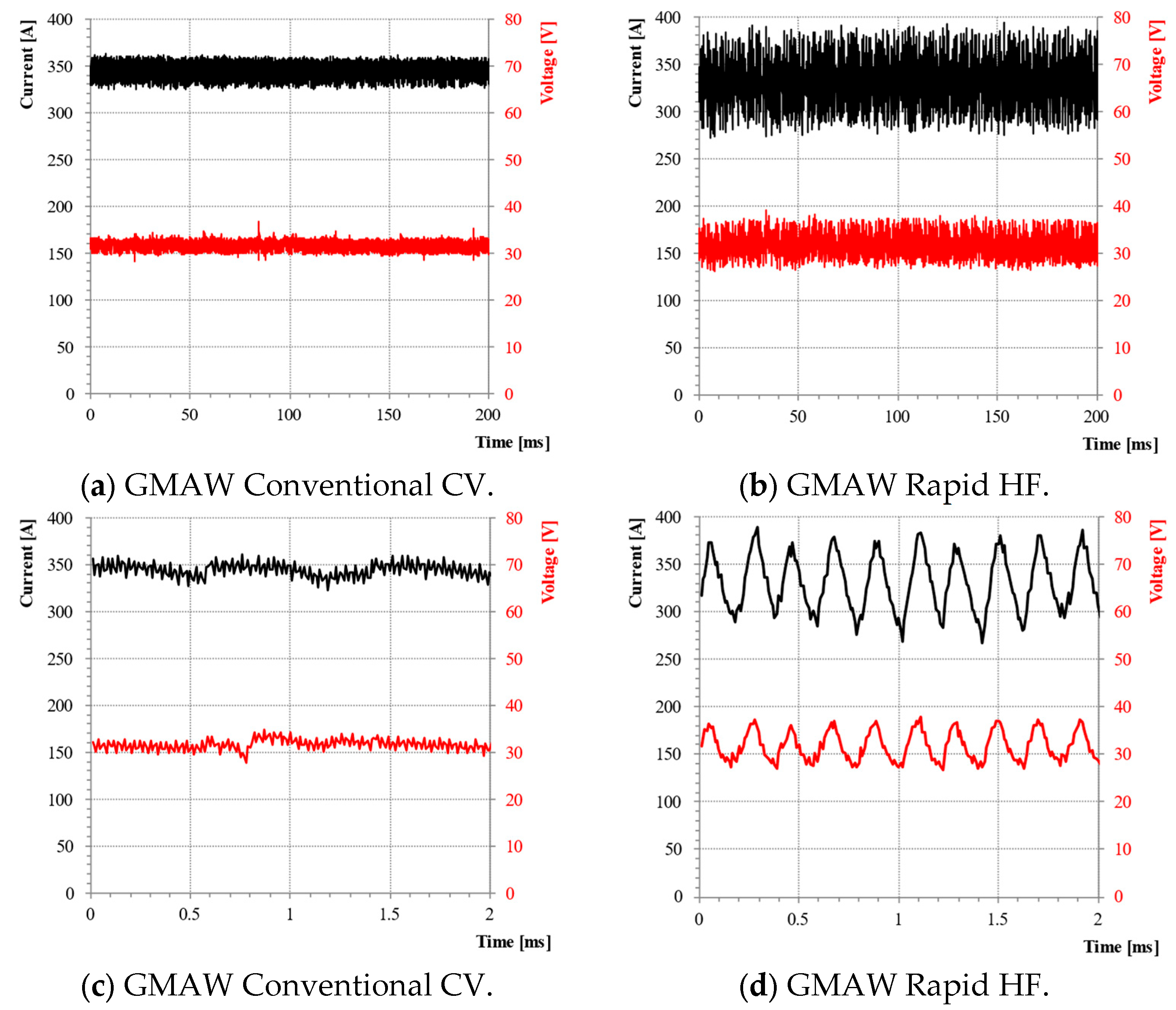
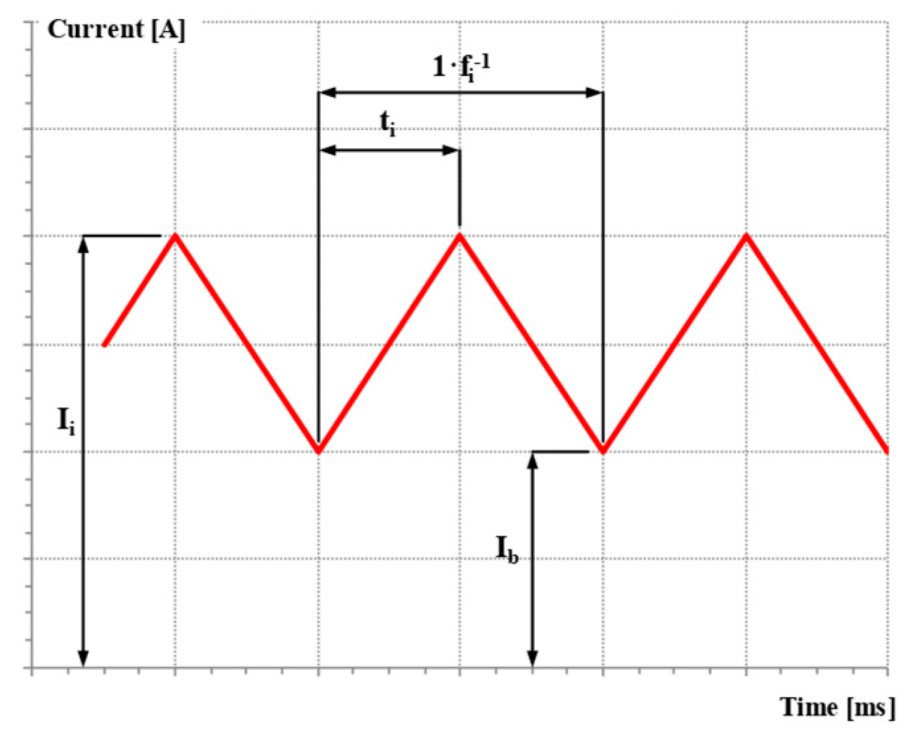
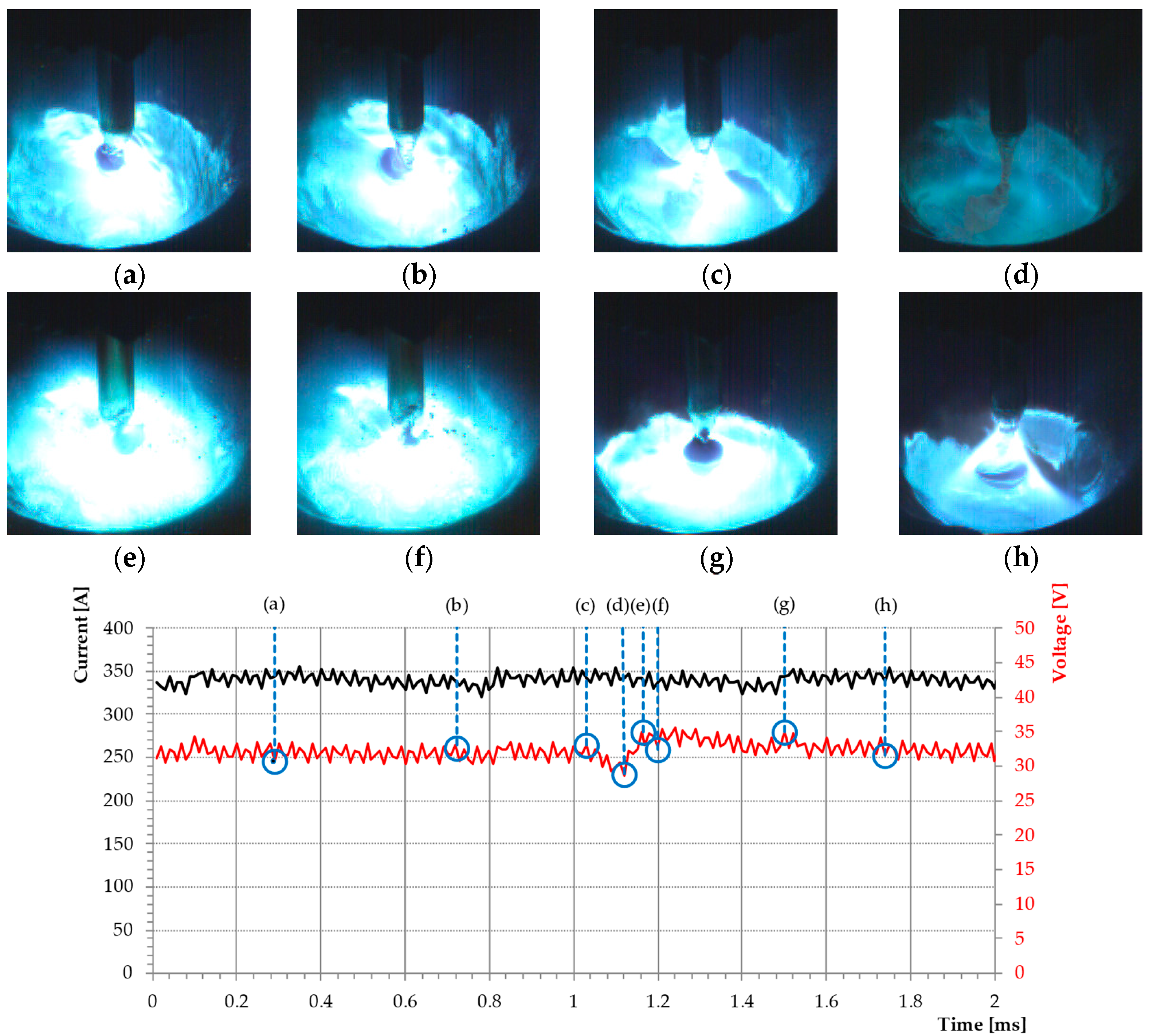
3.2. The Effect of the Impact of High-Frequency Pulsation on the Stabilization of a Buried Welding Arc

Based on the conducted welding tests, the recorded waveforms of current and voltage, and imaging of the space between electrodes with the application of a high-speed video camera, it was ascertained that a high-frequency impulse current guarantees a significantly higher, in comparison with GCCV, stability of the process conducted with the application of a buried welding arc. In GCCV, we can observe a welding arc burning interruption brought about stochastically and found to occur, with short-circuits interrupting the stable streaming transfer, which is possible to be observed over time in the form of fluctuations in the voltage of a welding arc (point d on the graph in Figure 13). During short-circuits, we can observe a lack of stability in the metal flow from the electrode to the pool, bringing about the formation of welding spatter (Figure 13e). The observed instability of the transport of metal is found to occur in the lower ranges of a welding current (250–330 A) and the speed of the feed of a welding wire (9–11 m/min) matching a transition metal transfer, when, depending on the value of a voltage, projected transport is used instead (Figure 13g), and, in the further course, becomes a repelled one (Figure 13e), as a result of which a small droplet spatter is formed (Figure 13f). Similar disturbances were observed by Silva et al. [3], where, to stabilize the process, a change was made in the dynamic properties of the power source by regulating the speed of increasing current at the moment of a short-circuit.
Applying a high-frequency current on the innovative Rapid HF process in question brings about the concentrations of the arc column and increase of the power density while shortening the length of a welding arc, ipso facto, stabilizing the narrowing formed at the end of a welding wire. The obtained metal transport is characterized by homogeneous streaming transfer with minimal deviations of the stream of liquid metal from the wire axis, preventing an adverse rotation of a welding arc (Figure 14).
In the case of the application, as a gas shield, pure carbon dioxide, the melting of droplets assumes, similarly to the case of GCCV, a form of repelled transport. High-frequency guarantees, however, stabilizing the “keyhole” inside a welding pool, owing to which freely detached droplets do not leave a “keyhole” and do not form a spatter characteristic for welding with pure CO2 shielding gas. This fact opens new roads for the application. In the course of welding, carbon dioxide is a gas characterized by high thermal conductivity and constituting welds that have a favorable deep penetration while simultaneously minimizing the spatter. In the case of GCCV, it was observed that, in a liquid pool, a temporary disappearance of the “keyhole” occurs, and transport becomes irregular and repelled. Closing the “keyhole” is an unwanted effect because it does not guarantee obtaining a stable penetration, and increases spatters and forms different welding imperfections, which is also confirmed by Baba et al. [35].

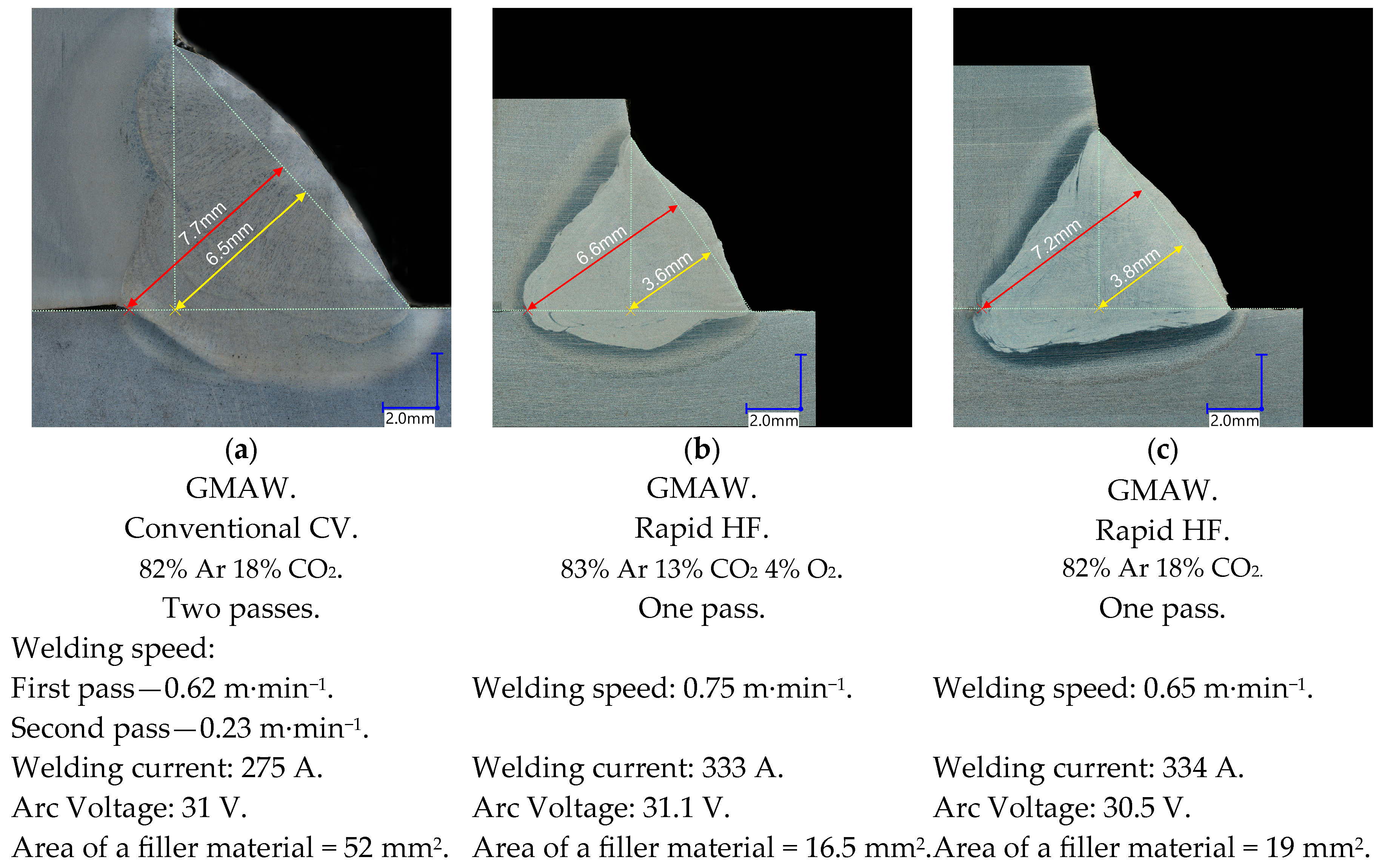
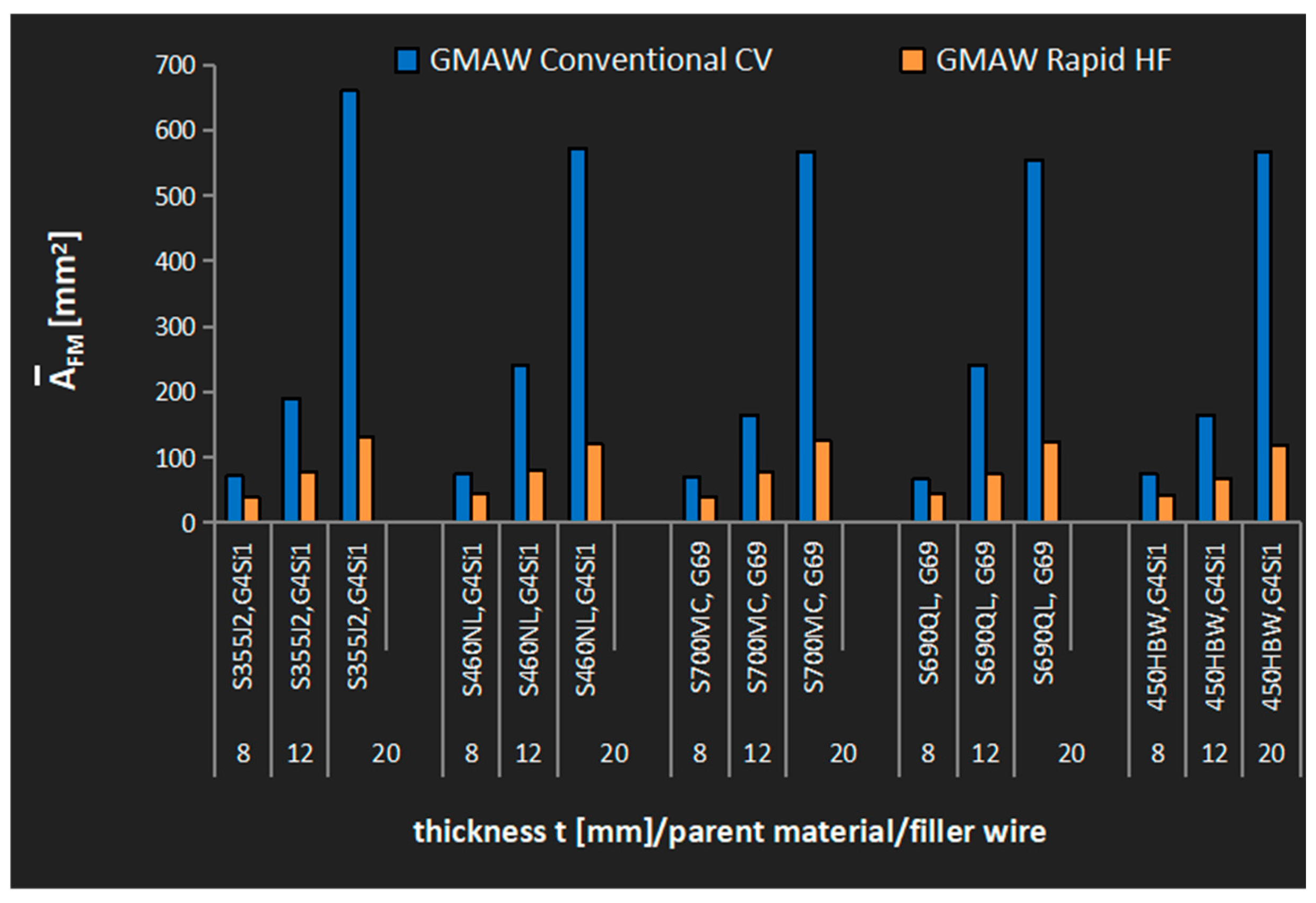
3.3. The Assessment of the Effectiveness of Welding with the Application of the Rapid HF Process

To determine the influence of high-frequency buried welding arc, the GRHF technology on forming welds, and that of the use of filler metals consumption, research into 360 joints with fillet welds, fillet–butt and the butt ones, was performed on T-joints and cruciform welded (one- and both-sided).
The joints were characterized by a changing nominal throat thickness of the welds. For further analyses, those that achieved the strength at the level of a parent material (PM) or maximum load-carrying capacity of weld were selected—the latter choice was made in the case of joints on which a deposited metal had a lower strength than PM and/or a rupture occurred on the area of welds. The results obtained were compared with identical joints made hitherto with the application of GCCV welding technology.
One of the objectives of conducting the above-mentioned research was to determine the possibility of decreasing the consumption of filler metals on welded joints while assuming a tendency toward the maximum load-carrying capacity of weld (a rupture on a base material or within the scope of the strength of base material).
To assess the effectiveness of the GRHF buried welding arc, the factor of the filler metals consumption expressed by Equation (2) were calculated. The assessment covered joints with a full or maximum load-carrying capacity of the weld made of base and filler materials collated in Table 1.
A FM = π · d e 2 4 · V e V s · k
where de is the diameter of a welding wire (mm), Ve is the speed of the rate of a welding wire (m/min), vs. is the welding speed (m/min), and k is the number of welds (having those exact dimensions) on a joint.
The factor of the filler metal consumption AFM in mm2 presented in Equation (2) matches the cross-section of the parts of welds without the penetration area presented in Figure 15 (marked with the use of yellow color). Joints made with the application of the GCCV process are characteristic in the case of welds having low penetration (the penetration marked with the use of blue color) and also a substantial consumption of filler metals, whereas welded joints made with the application of the GRHF process have deeply penetrated welds made with a much smaller consumption of filler metals. What was obtained was the destruction (rupture) of welded joints at the level of strength of a base material, beyond areas where welds are situated. The obtained results prove it is justified to apply the GRHF process in restricting the consumption of filler metals while maintaining a high load-carrying capacity of joints with deep penetration welds.
Savings in the consumption of filler metals in the GRHF process compared with standard technology (GCCV) presented in Figure 16 fluctuated between 30–40% for joints with the thickness of t = 8 mm and 80% for joints with the thickness of t = 20 mm.

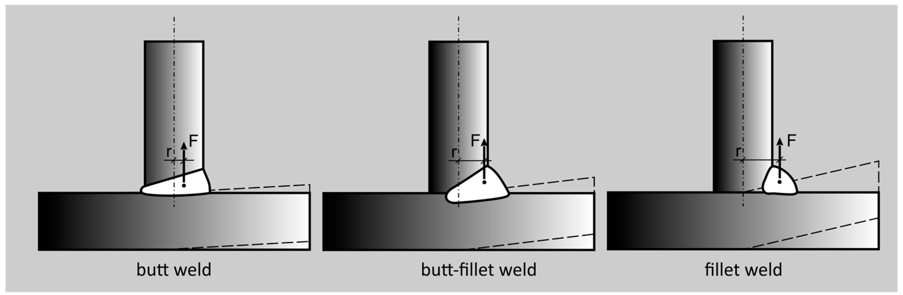
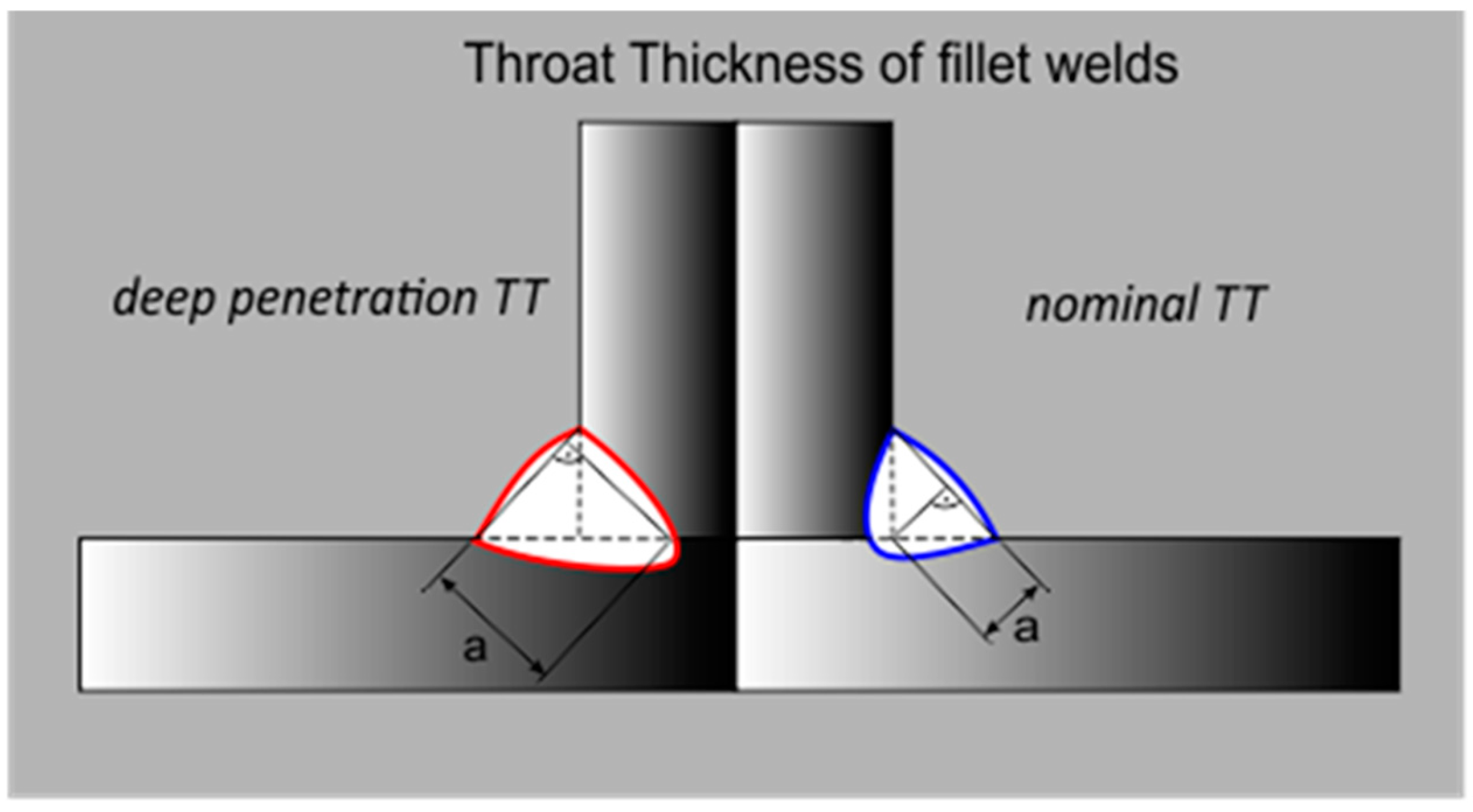
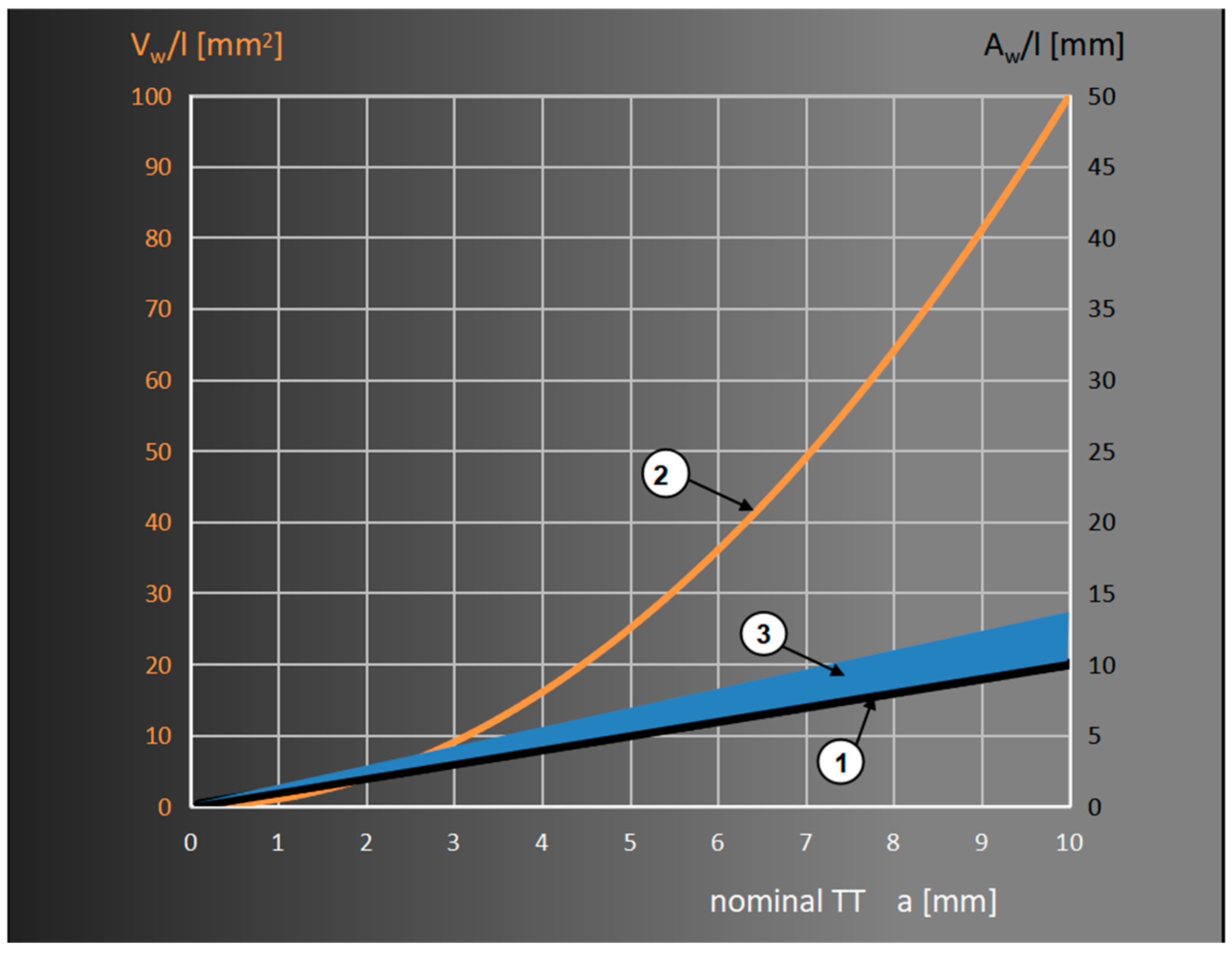
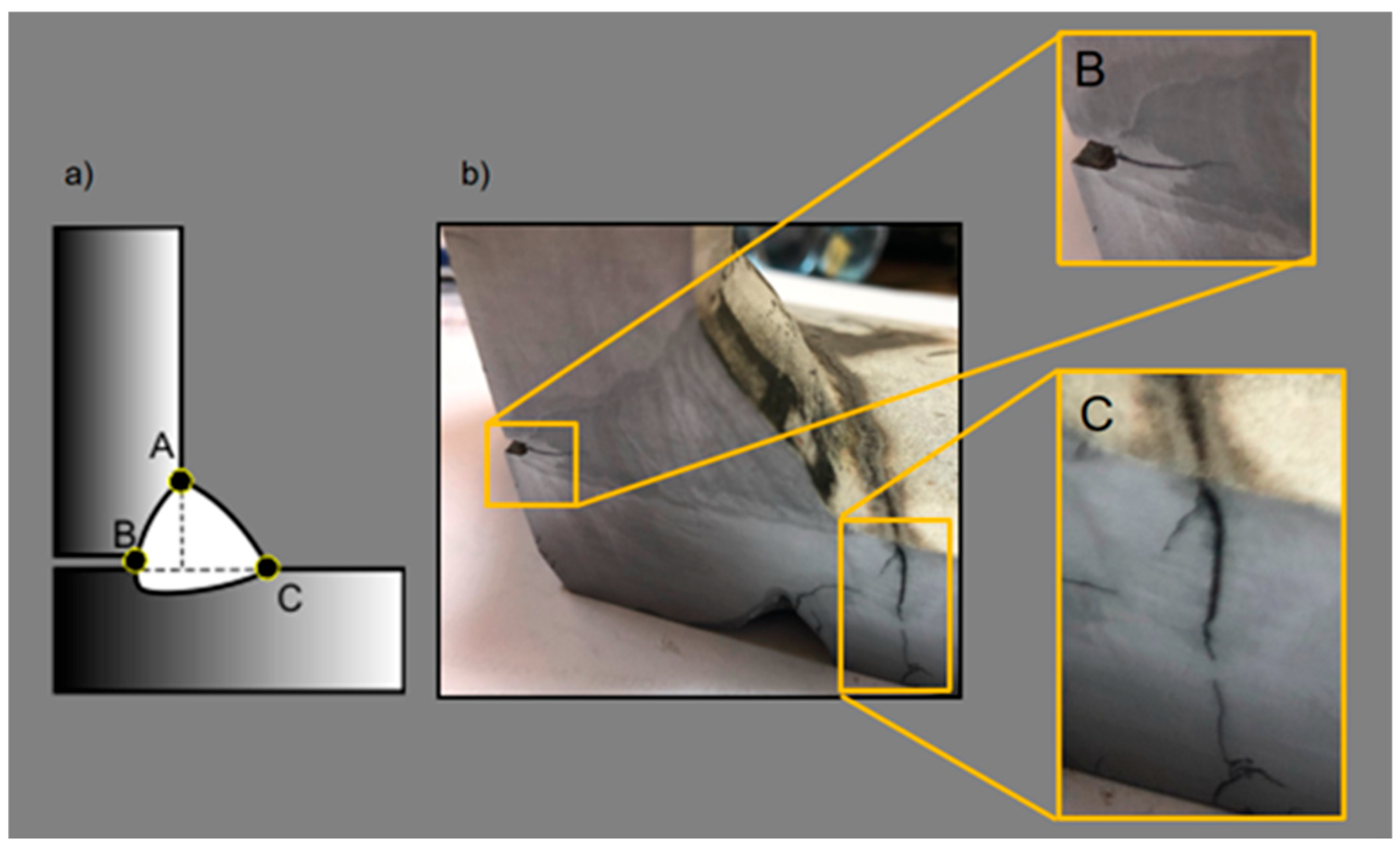
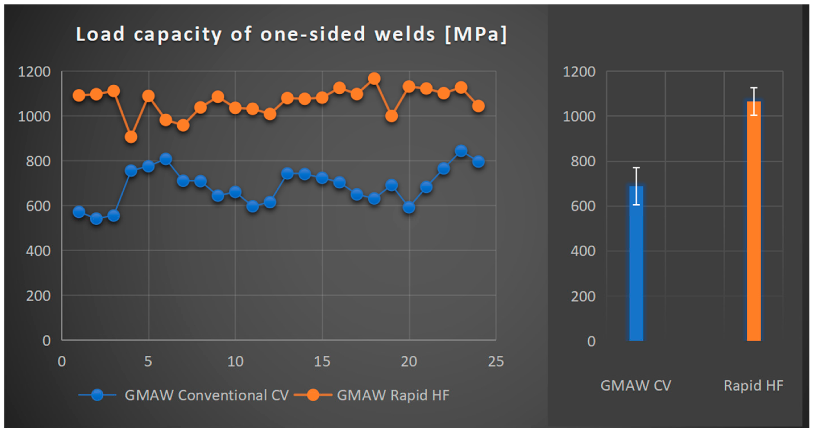
3.4. Analysis of the Load-Carrying Capacity of One-Side Fillet Welds/Fillet–Butt Welds Made with the Application of the GMAW Rapid HF Process

Calculating the stresses originating from the external loads on fillet welds, conducted for 130 years according to the requirements of designing and making welded constructions, has undergone numerous changes and modifications. Initially, it was claimed that, as they were destroyed on a bisector plane, they ended up sharing [36]. It was assumed that by calculating all and any stresses, it is possible to determine the section of that plane at the angle of 450 (for symmetrical welds) on the plane of the drawing (Figure 17a). The obtained field or section modulus/polar section modulus was seen as load-bearing factors while determining stresses, which always were of shearing character [37]. This method was not only paradoxical because it predicted tangent stresses occurring in three mutually perpendicular directions, but also, due to its lack of precision, it brought about a significant, even by several tens of percent, change in the dimensions of welds [38]. Its application is permitted by the Eurocode 3 [1], but as a simplified method because it does not require the distribution of forces impacting the bi-sectorial plane of welds, and, therefore, further calculations. Numerous studies in the field of the load-carrying capacity of fillet welds in the case of the complex states of stresses brought about, initially, as far as the specific cases were concerned, and in the further course more generally, determining the full ellipsoids of the strength of fillet welds for different steels [39], and, in the further course, determining appropriate models based on the hypothesis of Huber–Mises–Hencky [1,40]. In contrast to the simplified method, the directional method of the distribution of stresses on a bisector plane of welds is compatible with the actual mechanism of cracking fillet welds resulting from standard exploitation.
This method accurately represents the load-carrying capacity of fillet welds under the influence exerted by external loads. It is assumed that stress is not concentrated on the ends of welds, and the distribution of stresses is homogeneous all over the cross-section [40].
It ought to be indicated that, in the case of an angle different than that of 45 degrees, which means when its sine is not equal to cosine, calculations become somewhat more complicated because asymmetric fillet welds are applied. The lack of effectiveness of making and using fillet welds with unequal legs was proved in the authors’ own research [10]. The instance referred to hereinabove presents that the directional method of calculating fillet welds is quite simple and, however, brings about the practical and economical designing and application of fillet welds. The change in their dimensions (assuming, in the case of numerous constructions, an excessive leg size of welds) has been the main problem for many years in the case of welded constructions. Taking into consideration the fact that fillet welds outnumber butt ones and represent higher masses (to the degree reaching 9:1), it brings about excessive rigidity, fragility, and cracking of joints made even of steels with good weldability.
To compare the load-carrying capacity of welds made with the application of the GRHF process and GCCV, for assessment, T-joints made of the S355J2 steel with one-side welds were chosen, with the critical points of joints bringing about the formation of cracks and destruction from the root in the direction of weld faces, following the scheme presented in Figure 5.
The calculation was conducted in accordance with the Eurocode. The following were assumed:
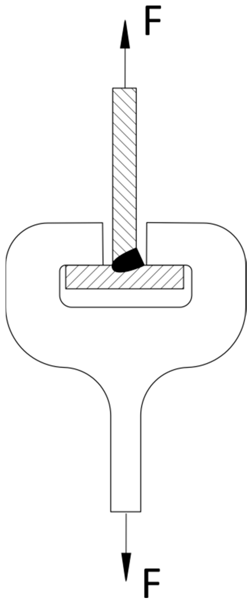
  • F force acts axially along the web of a T-joint (Figure 18);
  • The field of load-bearing cross-section welds in mm2 is as follows:
    A w =   a · l
    where a is the throat thickness calculated for fillet welds/fillet–butt welds (mm), and l is the length of fillet welds/fillet–butt welds (mm);
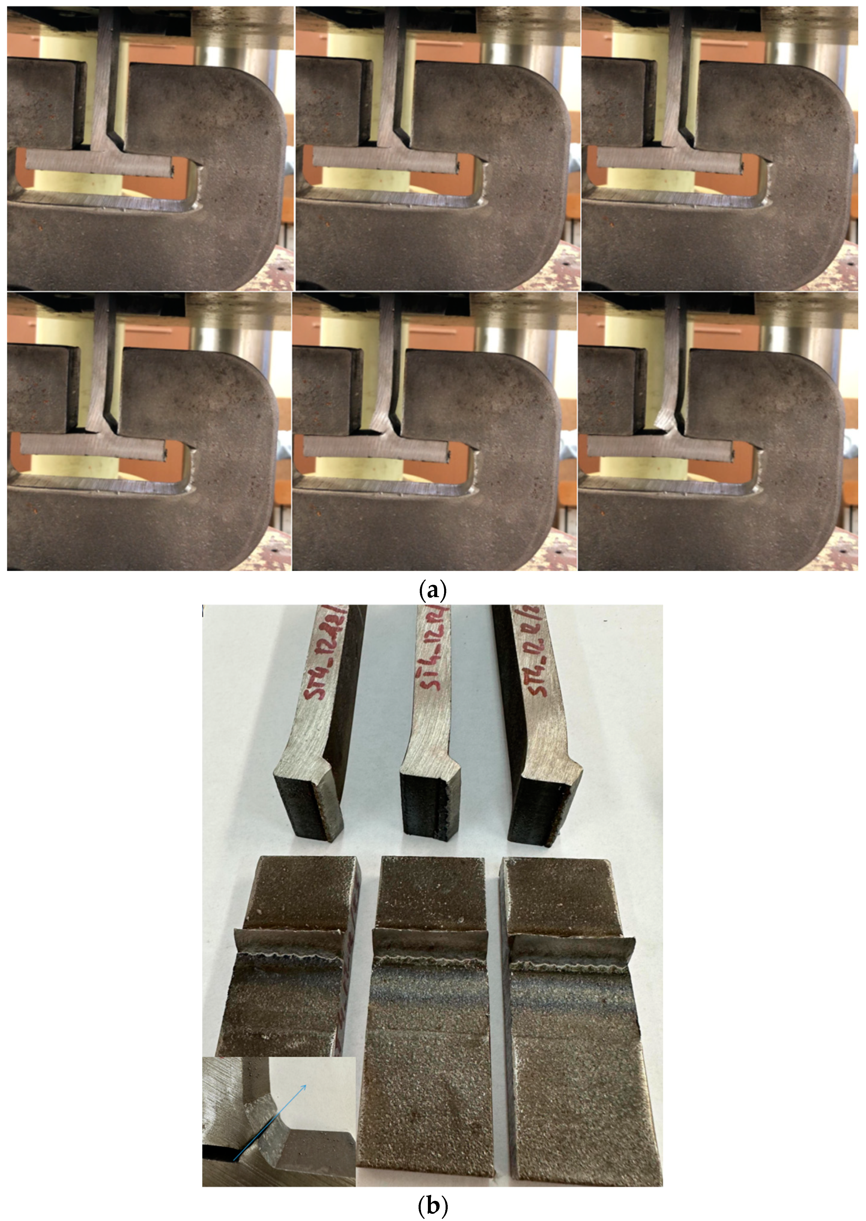
  • Welds (in accordance with the results of research) undergo destruction starting from the root point—on the axis of the joints in the direction of the weld face (Figure 19a);
  • Welds have the same transverse dimension on the entire length of welds.
Stress on fillet/fillet–butt welds amounts to the following:
σ z = σ 2 + 3 τ 2 + τ 2   f u β w · γ M 2
where σ, τ, and τ are the constituents of the state of stresses on cross-section welds, respectively, normal and shear to the plane of cross-section; fu is the nominal tensile strength of the weaker of the joined materials—within the scope of 360–560 MPa for t ≤ 40 mm.
f u = R m
Βw is the correlation co-efficient taking under consideration the higher mechanical properties of the material of a weld in comparison with the material (for the S355J2 steel Βw = 0.85), and γM2 = 1.25 is the factor of safety in the case of testing the load-bearing cross-section capacity on a rupture).
In the case of welds having a cross-section of symmetrical fillet welds,
τ = 2 2 F A w = 0.707 F A w
Because shear stresses amount to τ = 0 for the considered case, the equation of equivalent stresses on welds are as follows:
σ z = σ 2 + 3 τ 2 f u β w · γ M 2
σ z = F · 2 A w
Thus calculated, equivalent stresses constitute a load-carrying capacity of welds in the case of the studied welded joints.
In Figure 20, the results of destructive research on joints with one-side welds made with the application of the GCCV and GRHF are presented.
Conducted research into load-carrying capacity welds on the researched joints indicated its increase for a deeply penetrating GRHF welding in comparison with the one made with the hitherto in use GCCV. In particular, it is significant that there is an increase in the load-carrying capacity, which achieved the mean value of 1066 MPa (standard deviation 62 MPa), which, in comparison with GCCV welding of 688 MPa (standard deviation 83 MPa), constitutes an increase in the load-carrying capacity at the level of 55%, confirming, ipso facto, a decisive influence of deeper penetration on the load-carrying capacity of welds accompanied by a simultaneous decrease in the filler material consumption.
Micrographs of the base material (S355J2) and the welds of GCCV (first pass: welding current: 275 A, arc voltage: 31 V, welding speed: 0.62 m/min; second pass: welding current: 275 A, arc voltage: 31 V, welding speed: 0.23 m/min), and GRHF (welding current: 334 A, arc voltage: 30.5 V, welding speed: 0.65 m/min) welding were observed and compared. Figure 21 shows cross-sectional photographs of the central part of the welds made with both welding processes. In GCCV welding, the primary microstructures are coarse grain boundary ferrite and side plates ferrite, with small amounts of acicular ferrite. In contrast, weld metals produced with GRHF contain fine-grained boundary ferrite and a higher proportion of acicular ferrite.
The phenomenon of joint destruction is similar in both welding processes GCCV and GRHF. The initial cracks start at point B (Figure 5 in the article), located in a weld root, and then develop across a bisector plane of welds. The fracture is plastic (Figure 19b). The range of load carrying capacity was different, as shown on Figure 20. The greater load-bearing capacity of welds made with GRHF, compared to those made with GCCV, is primarily due to the greater effective weld throat and the higher content of acicular ferrite.

4. Conclusions

When applying the methods of deep penetration welding, including the GMAW Rapid HF process, it is possible to accomplish a few important objectives in construction and economical use. The joints are durable, and their creation requires relatively little energy consumption, whereas the carbon footprint is significantly decreased, and so is the consumption of filler metals; consequently, the time required to build the construction may be significantly shortened. These advantages are ever more significant in the case of an increase in the thickness of joined elements. The findings were confirmed by numerous tests conducted with the application of various types of constructional steels.
The innovative process of GMAW Rapid HF, based on a high-frequency impulse current, has a favorable influence on the stabilization of buried welding arc and also creates an effective increase in penetration on a base material in a broad scope of applied shielding gases. This technology may be successfully applied in the production of deeply penetrated fillet welds, characterized by an increasingly effective cross-section load-carrying capacity, while considering increased depth penetration calculated per the Eurocode 3 [1].

Author Contributions

Conceptualization, K.K., K.M., and J.I.; methodology, K.K., K.M., and J.I.; software, K.M.; validation, K.K.; formal analysis, K.K., K.M., and J.I.; investigation, K.K., K.M., and J.I.; resources, K.K., K.M., and J.I.; data curation, K.K., K.M., and J.I.; writing—original draft preparation, K.K. and K.M.; writing—review and editing, K.K. and K.M.; visualization, K.K. and K.M.; supervision, K.K., K.M., and J.I.; project administration, K.K. and K.M.; funding acquisition, K.K. All authors have read and agreed to the published version of the manuscript.

Funding

This research was funded by European Funds, grant number POIR.01.01.01-00-0779/18. This study was provided by a joint research agreement between the Czestochowa University of Technology and Zugil S.A., Poland, within the project Opracowanie innowacyjnej technologii wytwarzania elementów i konstrukcji wielkogabarytowych, w tym dźwigowych ograniczającej odkształcenia konstrukcji spawanych wraz z pilotażową linią technologiczną w firmie Zugil S.A. (eng. Development of technology for structural and the large-size structures, including cranes limiting deformations of welded structures with a innovative technological line at Zugil S.A.).

Institutional Review Board Statement

Not applicable.

Informed Consent Statement

Not applicable.

Data Availability Statement

The original contributions presented in this study are included in the article. Further inquiries can be directed to the corresponding authors.

Acknowledgments

The authors are grateful for the support for this study by Radosław Pilarski (EC TEST Systems, Poland) for help with fast photo imaging with the use of the CAVILUX HF laser source.

Conflicts of Interest

The authors declare no conflicts of interest.

References

  1. EN 1993-1-8:2005; Design of Steel Structures—Part 1–8: Design of Joints. European Committee for Standardization: Brussels, Belgium, 2005.
  2. Baba, H.; Kadota, K.; Era, T.; Ueyama, T.; Maeshima, M.; Kadoi, K.; Inoue, H.; Tanaka, M. Single-pass full-penetration welding for thick stainless steel using high-current GMAW. Weld. Int. 2021, 35, 240–253. [Google Scholar] [CrossRef]
  3. Silva, J.H.G.; Dutra, J.C.; Schwedersky, M.B.; Marques, C.; Riffel, K.C.; Bernard, R.A. Dynamically-Flexible Arc—A Novel Interpretation for the High Performance GMAW. In Proceedings of the 29th International Ocean and Polar Engineering Conference (ISOPE 2019), Honolulu, HI, USA, 19–21 June 2019. [Google Scholar]
  4. Szczesny, M. Shielded Arc Welding Process and Device. EP1640100B1, 24 September 2004. [Google Scholar]
  5. Komen, H.; Baba, H.; Kadota, K.; Era, T.; Tanaka, M.; Terasaki, H. Three-dimensional particle simulation of buried space formation process during high current gas metal arc welding. J. Adv. Join. Process. 2020, 1, 100019. [Google Scholar] [CrossRef]
  6. ISO 2553:2019; Welding and Allied Processes—Symbolic Representation on Drawings—Welded Joints. International Organization for Standardization: Geneva, Switzerland, 2019.
  7. AWS A3.0M/A3.0:2010; Standard Welding Terms and Definitions Including Terms for Adhesive Bonding, Brazing, Soldering, Thermal Cutting, and Thermal Spraying 12th Edition. American Welding Society: Miami, FL, USA, 2009.
  8. ISO 17659:2002; Welding—Multilingual Terms for Welded Joints with Illustrations. International Organization for Standardization: Geneva, Switzerland, 2002.
  9. Uzunali, U.Y.; Cuvalci, H. Review of the definition of weld penetration, depth of fusion and throat thickness on fillet welds. Gazi Univ. J. Sci. 2023, 36, 1746–1757. [Google Scholar] [CrossRef]
  10. Kudła, K.; Wojsyk, K. The rational use of fillet welds and butt-fillet welds in welded structures. Weld. Tech. Rev. 2019, 91, 7–13. [Google Scholar]
  11. Mikkola, E.; Murakami, Y.; Marquis, G. Fatigue life assessment of welded joints by the equivalent crack length method. Procedia Mater. Sci. 2014, 3, 1822–1827. [Google Scholar] [CrossRef]
  12. Tso-Liang, T.; Chin-Ping, F.; Peng-Hsiang, C.; Wei-Chun, Y. Analysis of residual stresses and distortions in T-joint fillet welds. Int. J. Pres. Ves. Pip. 2001, 78, 523–538. [Google Scholar] [CrossRef]
  13. Barsoum, Z.; Lundbäck, A. Simplified FE welding simulation of fillet welds—3D effects on the deformation residual stress. Eng. Fail. Anal. 2009, 16, 2281–2289. [Google Scholar] [CrossRef]
  14. Yang, L.; Cui, Y.; Wei, X.; Li, M.; Zhang, Y. Strength of duplex stainless steel fillet welded connections. J. Constr. Steel Res. 2019, 152, 246–260. [Google Scholar] [CrossRef]
  15. Torabian, S.; Xiao, F.; Haws, R.B.; Schafer, B.W. Design of transverse fillet welds in the lapped joints of thin steel plates. Int. J. Steel Struct. 2018, 18, 337–348. [Google Scholar] [CrossRef]
  16. Dundu, M. Mathematical model to determine the weld resistance factor of asymmetrical strength results. Structures 2017, 12, 298–305. [Google Scholar] [CrossRef]
  17. Wojsyk, K.; Nawrocki, J. Study of the impact of lack of fusion in the fillet weld on its fatigue strength under various load combinations. Weld. Tech. Rev. 2019, 91, 17–24. [Google Scholar]
  18. Grimsmo, E.L.; Daehli, L.E.; Hopperstad, O.S.; Aalberg, A.; Langseth, M.; Clausen, A.H. Numerical study of fillet welds subjected to quasi-static and impact loading. Sciences 2017, 131–132, 1092–1105. [Google Scholar] [CrossRef]
  19. Khurshid, M.; Barsoum, Z.; Mumtaz, N.A. Ultimate strength and failure modes for fillet welds in high strength steels. Mater. Des. 2012, 40, 36–42. [Google Scholar] [CrossRef]
  20. Mellor, B.G.; Rainey, R.C.T.; Kirk, N.E. The static strength of end and T fillet weld. Mater. Des. 1999, 20, 193–205. [Google Scholar] [CrossRef]
  21. Perić, M.; Tonković, Z.; Rodić, A.; Surjak, M.; Garasić, I.; Boras, I.; Svaić, S. Numerical analysis and experimental investigation of welding residual stresses and distortions in a T-joint fillet weld. Mater. Des. 2014, 53, 1052–1063. [Google Scholar]
  22. ISO 9018:2016-01; Destructive Tests on Welds in Metallic Materials—Tensile Test on Cruciform and Lapped Joints. International Organization for Standardization: Geneva, Switzerland, 2016.
  23. ISO 14341:2020; Welding Consumables—Wire Electrodes and Weld Deposits for Gas Shielded Metal Arc Welding of non Alloy and Fine Grain Steels—Classification. International Organization for Standardization: Geneva, Switzerland, 2020.
  24. ISO 16834:2025; Welding Consumables—Wire Electrodes, Wires, Rods and Deposits for Gas Shielded Arc Welding of High Strength Steels—Classification. International Organization for Standardization: Geneva, Switzerland, 2025.
  25. ISO/TR 17671-1:2002; Welding—Recommendations for Welding of Metallic Materials. Part 1: General Guidance for Arc Welding. International Organization for Standardization: Geneva, Switzerland, 2002.
  26. Lancaster, J.F. The Physics of Welding, 2nd ed.; Pergamon Press: Oxford, UK, 1986. [Google Scholar]
  27. Lin, M.A.; Eagar, T.W. Pressures Produced by Gas Tungsten Arcs. Metall. Trans. B 1986, 17, 601–607. [Google Scholar] [CrossRef]
  28. Matsunawa, A.; Yamamoto, H.; Hiramoto, S. Pulsed arc welding. Q. J. Jap. Weld. Soc. 1984, 53, 284–322. [Google Scholar]
  29. Krivtsun, I.; Demchenko, V.; Krikent, I.; Reisgen, U.; Mokrov, O.; Sharma, R. Characteristics of high-frequency pulsed current arc with refractory cathode. Paton Weld. J. 2022, 13, 9–18. [Google Scholar] [CrossRef]
  30. Yang, M.; Zheng, H.; Qi, B.; Yang, Z. Effect of arc behavior on Ti-6Al-4V welds during high frequency pulsed arc welding. J. Materi. Process. Technol. 2017, 243, 9–15. [Google Scholar] [CrossRef]
  31. Yamazaki, K.; Suzuki, R.; Shimizu, H.; Koshiishi, F. Spatter and fume reduction in CO2 Gas-Shielded Arc Welding by regulated globular transfer. Weld. World 2012, 56, 12–19. [Google Scholar] [CrossRef]
  32. Liskevych, O.; Scotti, A. Influence of the CO2 content on operational performance of short-circuit GMAW. Weld. World 2015, 59, 217–224. [Google Scholar] [CrossRef]
  33. Zielinska, S.; Pellerin, S.; Valensi, F.; Dzierzega, K.; Musiol, K.; Izarra, C.; Briand, F. Gas influence on the arc shape in MIG-MAG welding. Eur. Phys. J. Appl. Phys. 2008, 43, 111–122. [Google Scholar] [CrossRef]
  34. Tusek, J.; Suban, M. Experimental research of the effect of hydrogen in argon as a shielding gas in arc welding of high-alloy stainless steel. Int. J. Hydrog. Energy. 2000, 25, 369–376. [Google Scholar] [CrossRef]
  35. Baba, H.; Era, T.; Ueyama, T.; Tanaka, M. Single pass full penetration joining for heavy plate steel using high current GMA process. Weld. World 2017, 61, 963–969. [Google Scholar] [CrossRef]
  36. Bryła, S. Electrically welded iron bridge over the Słudwia River in Poland. Weld. Tech. Rev. 1929, 2, 186–194. [Google Scholar]
  37. Śledziewski, E. Projektowanie Stalowych Konstrukcji Spawanych, 1st ed.; WNT: Warsaw, Poland, 1972. [Google Scholar]
  38. Kudła, K.; Wojsyk, K. Method for analytical computation of stresses in fillet joints for complex load states—According to Eurocode 3. Weld. Tech. Rev. 2014, 86, 8–14. [Google Scholar]
  39. Ferenc, K.; Ferenc, J. Konstrukcje Spawane, 1st ed.; WNT: Warsaw, Poland, 2006. [Google Scholar]
  40. Wichtowski, B. Calculation of static and fatigue load capacity of welds in Eurocode 3. Weld. Tech. Rev. 2011, 83, 15–22. [Google Scholar]
Figure 1. Penetrations of base metals in the GMAW Conventional CV and GMAW Rapid HF processes.
Materials 18 01490 g001
Figure 2. Illustration of the formation of angular distortion in T-joints connected with various types of welds (F-force causing joint deformation, r-arm of force F between the neutral axis and the center of gravity of the weld cross-section).
Materials 18 01490 g002
Figure 3. Throat thickness (TT) of fillet welds with and without deep penetration.
Materials 18 01490 g003
Figure 4. Difference of strength increase (1) and volume (2) of symmetrical fillet weld with flat surface. (3) The area of possible increase in strength due to the increased penetration allowed by the standard Eurocode 3 [10].
Materials 18 01490 g004
Figure 5. Cracking of T-joints: (a) critical points of a joint, (b) view of a joint after a long-term fatigue load.
Materials 18 01490 g005
Figure 6. Scheme of the research station: 1—digital camera: PHOTRON 1024 PCI/PHANTOM VEO 710S, 2—light source: HMI lamp/laser Cavilux HF, 3—welding robot: Qirox QRC290, 4—measurement: DAQ NI USB-6251, 5—HF power welding source. The frequency of recording the image was 10,000 frames per second; the frequency of recording the parameters of current and voltage was 500,000 Hz.
Materials 18 01490 g006
Figure 7. Welding current and voltage waveforms at wire speed welding of 11 m·min−1, non-pulsing arc, and the high-frequency pulsation of arc. (a,b) Typical waveforms during welding; (c,d) detailed graph of waveforms. 82% Ar 18% CO2, Ve = 11 m·min−1, CTWD = 16 mm.
Materials 18 01490 g007
Figure 8. Schematic diagram of current waveform and pulse parameters for the GMAW Rapid HF process.
Materials 18 01490 g008
Figure 9. The comparison of typical welding arc profile taken using the high-speed video camera in studied types of welding arc: (ad) GMAW Conventional CV; (eh) GMAW Rapid HF welding arc. In the case of welding arc phenomena for pure CO2, the image was taken 1 millisecond after drop detachment from the wire tip, when the weld current value was about 330 A.
Materials 18 01490 g009
Figure 10. Depth of the penetration of GMAW Conventional CV and GMAW Rapid HF with different shielding gases.
Materials 18 01490 g010
Figure 11. Some cross-sectional bead-on-plate weld tests presented in Figure 10.
Materials 18 01490 g011
Figure 12. Comparison of fillet weld profiles with joints having equal throats. The red line determines the effective throat of fillet weld—aeff, and the yellow line indicates fillet weld size a.
Materials 18 01490 g012
Figure 13. Arc phenomenon of the buried arc realized by CV power supply taken by synchronous high speed video camera (10 000 fps) and data acquisition card (500 000 Hz). 82% Ar 18% CO2, Ve = 11 m·min−1, CTWD = 16 mm.
Materials 18 01490 g013
Figure 14. Welding arc phenomenon of the buried welding arc with the Rapid HF process taken by a synchronous high speed video camera (10 000 fps) and data acquisition card (500 000 Hz). 82% Ar 18% CO2, Ve = 11 m·min−1, CTWD = 16 mm.
Materials 18 01490 g014
Figure 15. View of welded cruciform joints made with the application of the GMAW Conventional CV and GMAW Rapid HF processes (base material S355J2, filler wire G4Si1, and thickness t = 20/20/20 mm).
Materials 18 01490 g015
Figure 16. Mean value factor of the filler metal consumption A ¯ FM on cruciform welded joints with the application of the GMAW Conventional CV and GMAW Rapid HF processes.
Materials 18 01490 g016
Figure 17. Operation of the section of a calculated root planes (bisector) of fillet welds on the plane of a drawing (a); distribution of external stresses into constituents—on the bisector plane of fillet welds (b).
Materials 18 01490 g017
Figure 18. Direction and situation of the F force on the welded T-joints in the case of one-sided welds.
Materials 18 01490 g018
Figure 19. Destructive test of one-sided welds: (a) phases of destroying fillet/fillet–butt welds and (b) typical fractures of welded joints.
Materials 18 01490 g019
Figure 20. Load-bearing cross-section capacity of welds on joints made with the application of the GMAW Conventional CV method and the GMAW Rapid HF process (base material—S355J2, filler wire—G4Si1, shielding gas—82%Ar + 18%CO2).
Materials 18 01490 g020
Figure 21. Exemplary microstructures in GCCV and GRHF joints: (a,b) base material; (c,d) central region of the welds (filler wire—G4Si1, shielding gas—82%Ar +18%CO2).
Materials 18 01490 g021
Table 1. Chemical composition of welding wires and base materials (in wt-%).
ElementG4Si 1G69 2S355J2S460NLS700MCS690QL450HBW
C0.0710.080.1300.1760.0660.1410.200
Si0.910.600.0180.4550.0340.2880.350
Mn1.631.701.491.681.901.101.32
P0.070-0.1500.0110.0080.0100.015
S0.014-0.0500.00090.00050.00030.001
Cr 0.0210.250.0890.0350.0280.3300.980
Ni0.0331.50.0460.0140.0110.1900.040
Al0.002-0.0680.0200.0540.0570.087
Cu0.106-0.0520.0110.0110.2950.020
Nb--0.0250.0020.0470.0230.030
Ti0.009(Zr + Ti)-0.0010.0020.1430.0210.010
V0.001-0.0020.1090.0080.0050.010
B--0.00000.00020.00020.00260.0030
Mo0.0130.30.0100.0110.0040.1670.170
N--0.0060.0250.0000.00480.0400
1 ISO 14341:2020 [23]: G4Si1; DIN 8559: SG3; AWS A-5.18: ER 70S-6:S355J2, S460NL, 450HBW. 2 ISO 16834:2025 [24]: G69.4M Mn3Ni1CrMo; AWS A-5.28: ER 100 S-1: S700MC, S690QL.
Table 2. Welding parameters for the GCCV and the GRHF process with maximum cruciform joint strength.
ProcessWire Feed Rate
[m·min−1]
Welding Speed
[m·min−1]
CTWD
[mm]
Pulse
Frequency
[Hz]
Thickness PM
[mm]
Welding Current
[A]
Arc
Voltage
[V]
Heat
Input
[kJ·mm−1]
GCCV8.20.5015-824027.40.63
GCCV8.00.1515-1225020.01.60
8.8 (1P)0.6015- 25430.90.63
GCCV8.8 (2P)0.1515-2025231.02.50
8.0 (3P)0.1515- 23522.51.69
GRHF160.90145000843034.00.78
GRHF160.541650001243036.01.38
GRHF160.551650002043039.01.46
Heat input calculated by ISO/TR 17671-1:2002 [25] (thermal efficiency ratio—0.8), CTWD—Contact Tip to Workpiece Distance, wire diameter—1.2 mm, shielding gas—M21, gas flow—15 l·min−1, (1P, 2P, and 3P)—first, second, and third pass in the weld.
Table 3. Welding conditions and detailed pulse parameters for the GCCV and the GRHF test presented in Figure 7.
ProcessWire Feed Rate
[m·min−1]
Pulse Frequency
[Hz]
Peak
Current
[A]
Pulse
Time
[ms]
Base
Current
[A]
Response Rate
[A·ms−1]
Welding Current
[A]
Arc
Voltage
[V]
GCCV11-----34031.5
GRHF1150003800.1280100033028.5
Disclaimer/Publisher’s Note: The statements, opinions and data contained in all publications are solely those of the individual author(s) and contributor(s) and not of MDPI and/or the editor(s). MDPI and/or the editor(s) disclaim responsibility for any injury to people or property resulting from any ideas, methods, instructions or products referred to in the content.

