
Study and Simulation Analysis of Microwave Heating Performance of Magnetite Concrete Based on Random Aggregate Modeling

 ,
,
Abstract
1. Introduction
2. Materials and Methods
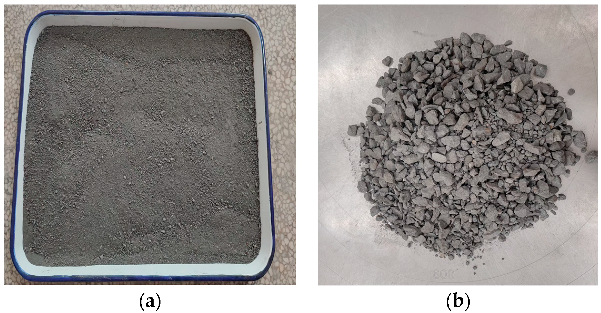
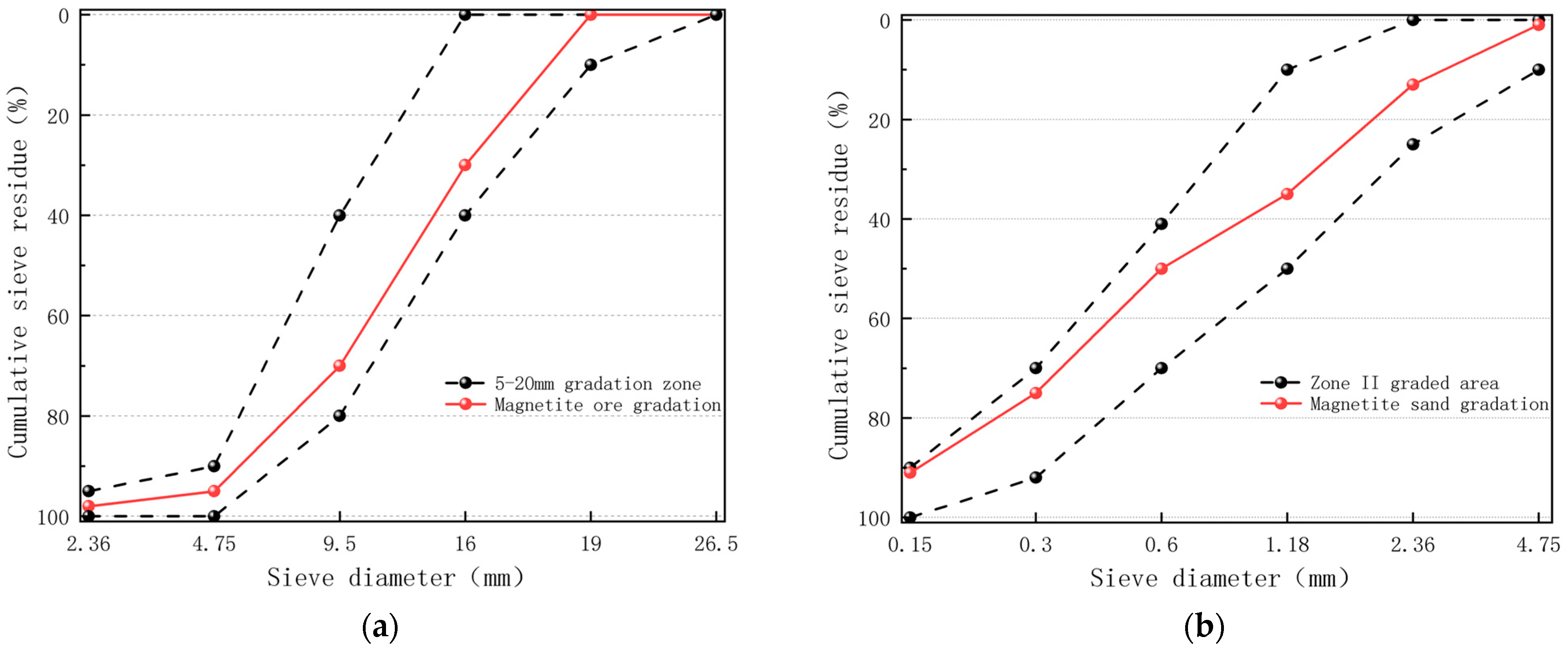
2.1. The Material Testing and Specimen Preparation
2.2. Experimental Methods
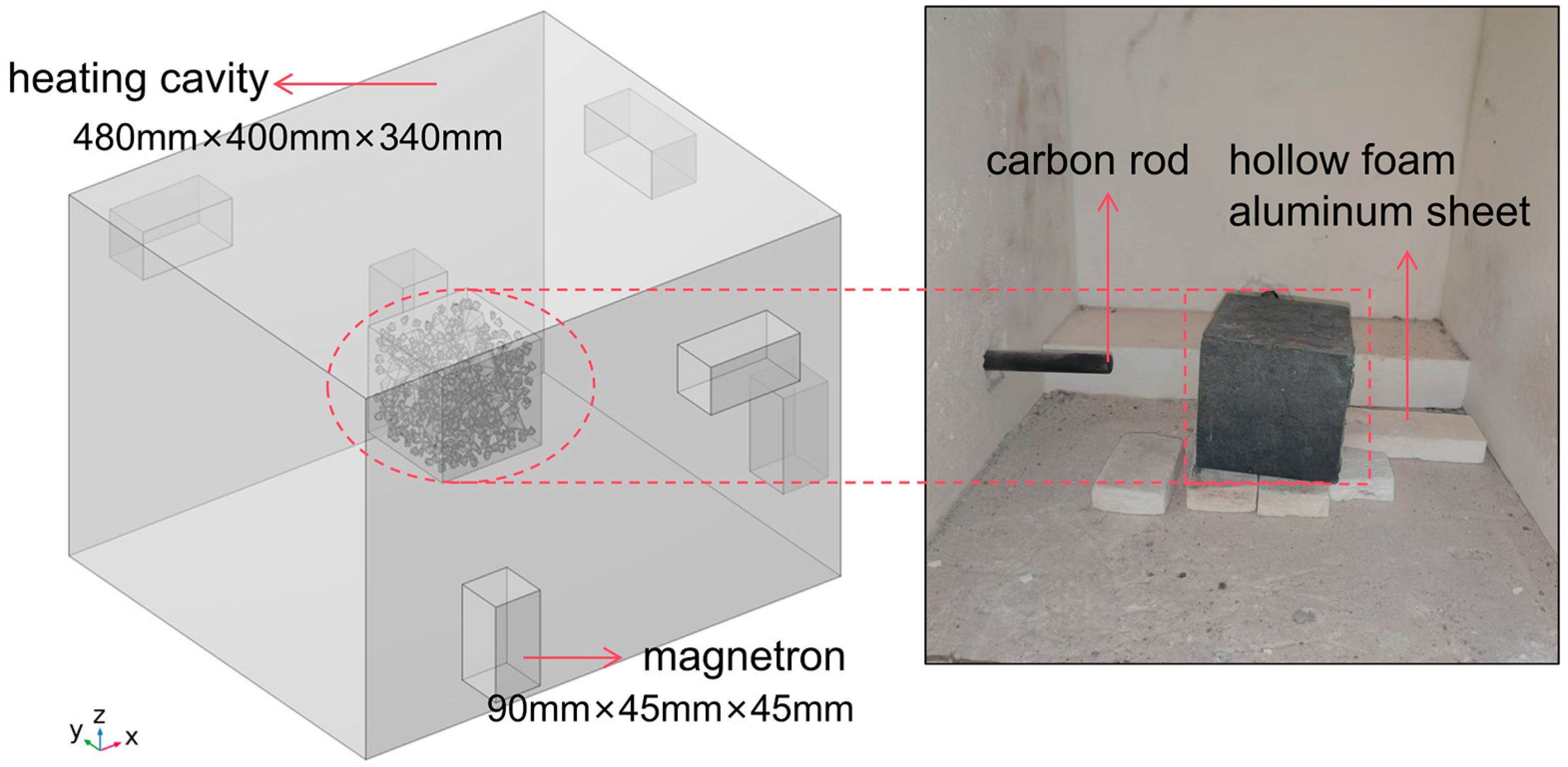
2.2.1. Microwave Heating Experiment
2.2.2. Mechanical Property Pesting Methods
2.3. 3D Finite Element Simulation
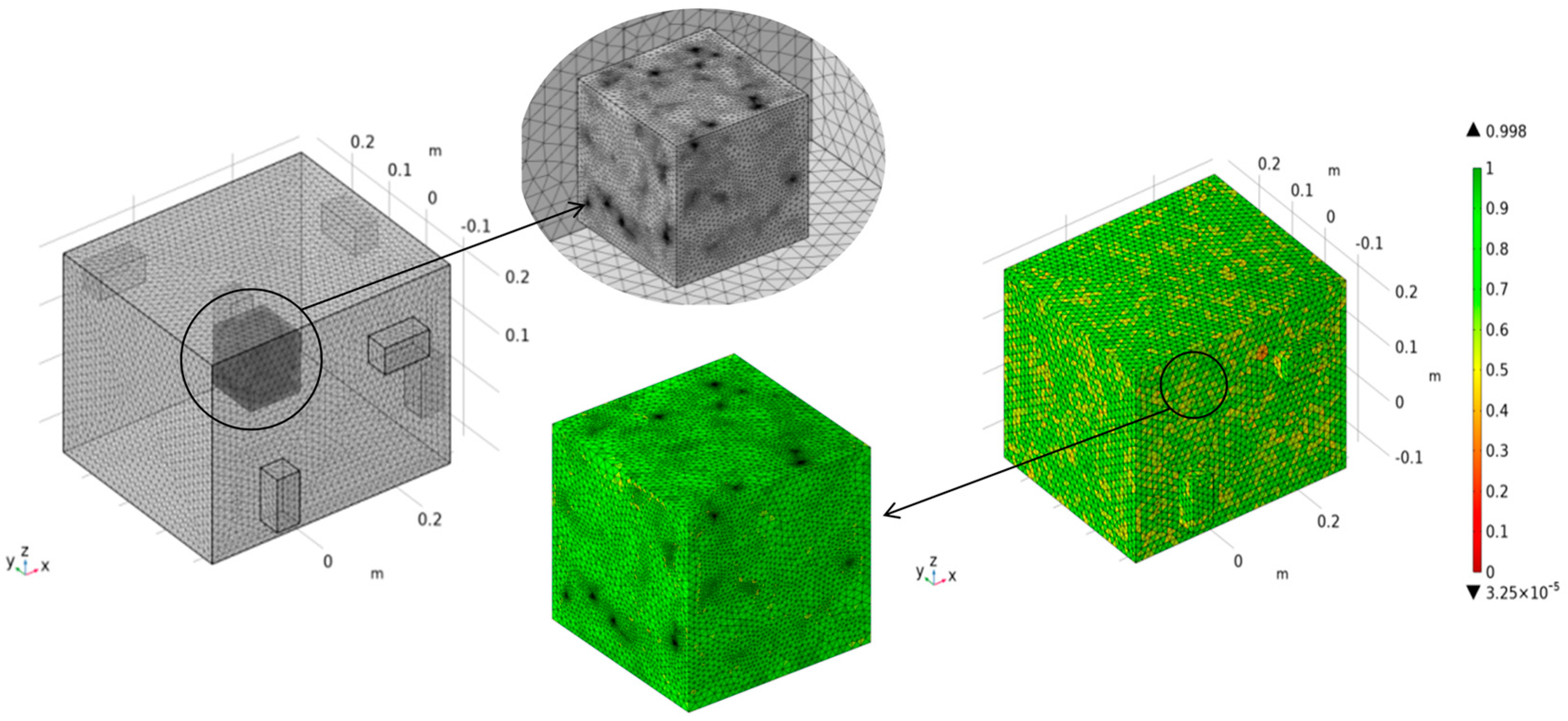
2.3.1. Stochastic Aggregate Modeling and Microwave Heating Simulation
2.3.2. Material Parameterization and Basic Assumptions
2.3.3. Microwave Heating Principle
2.3.4. Boundary Conditions
Grid Division
3. Results
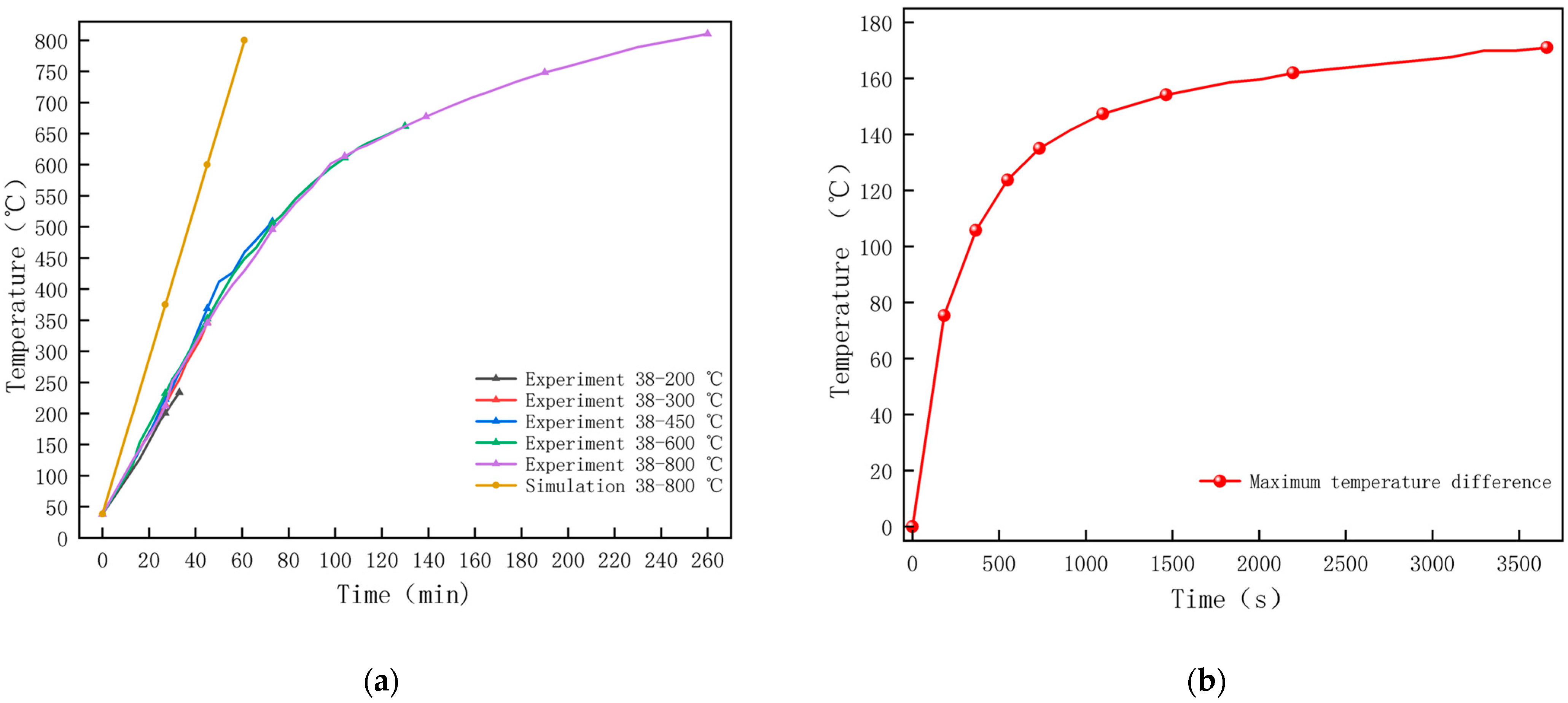
3.1. Model Validation
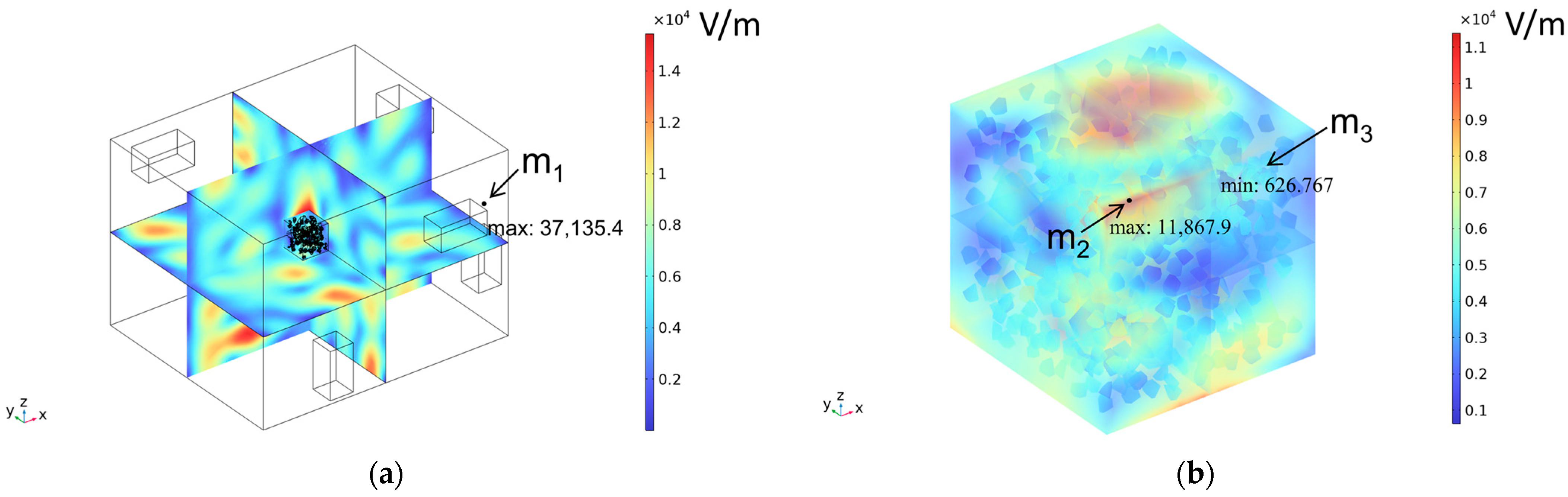
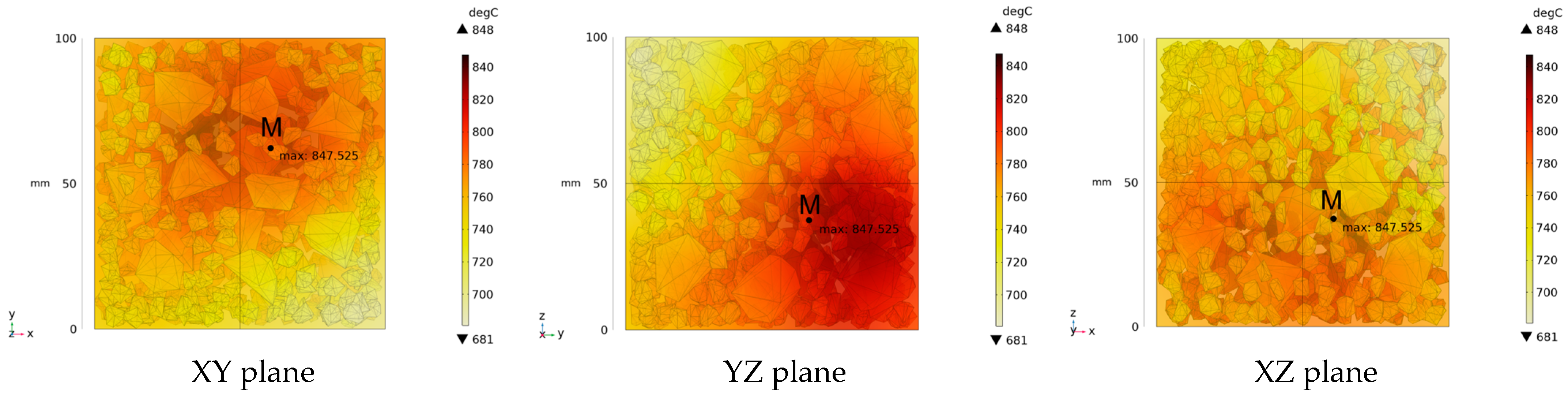
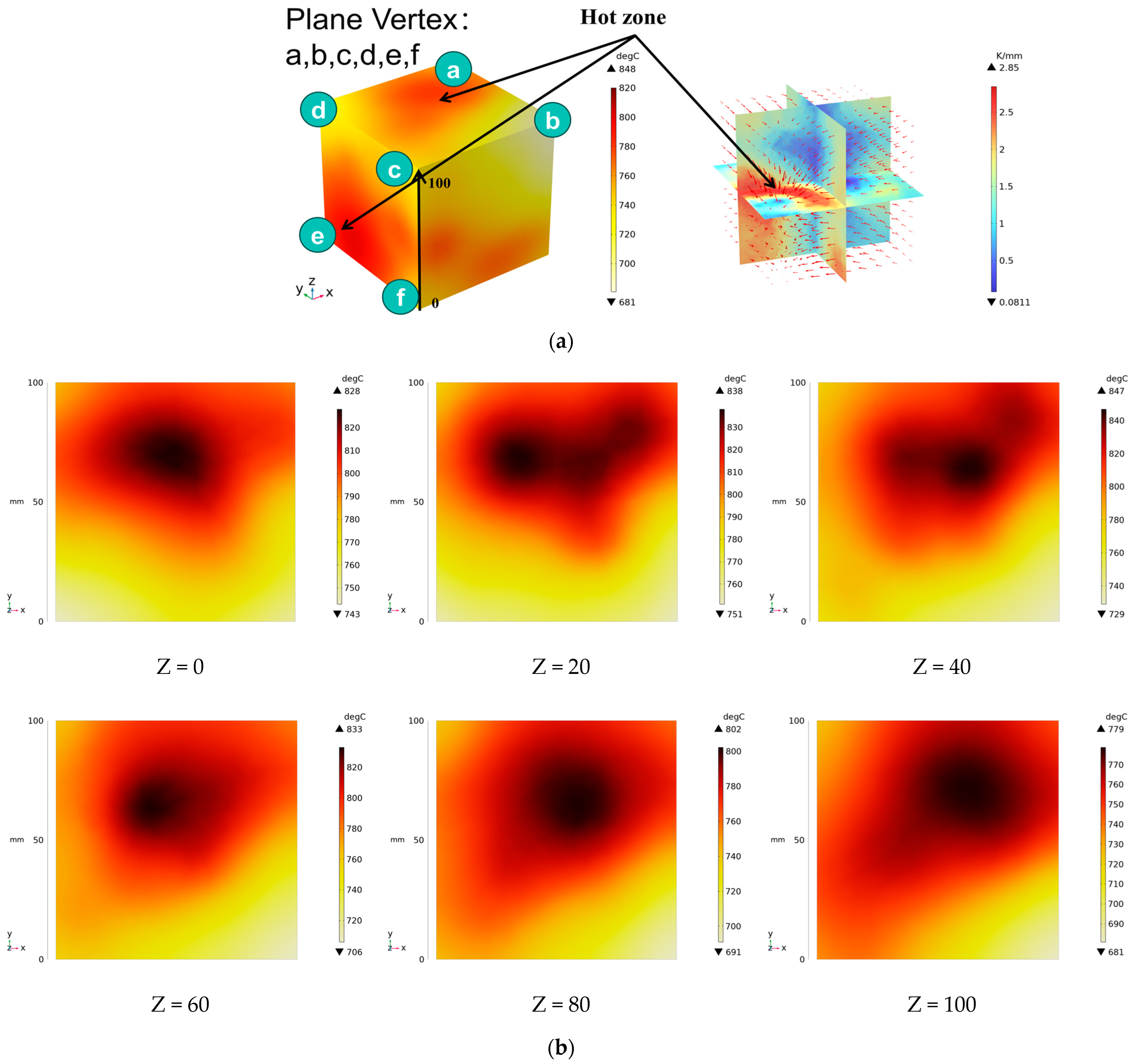
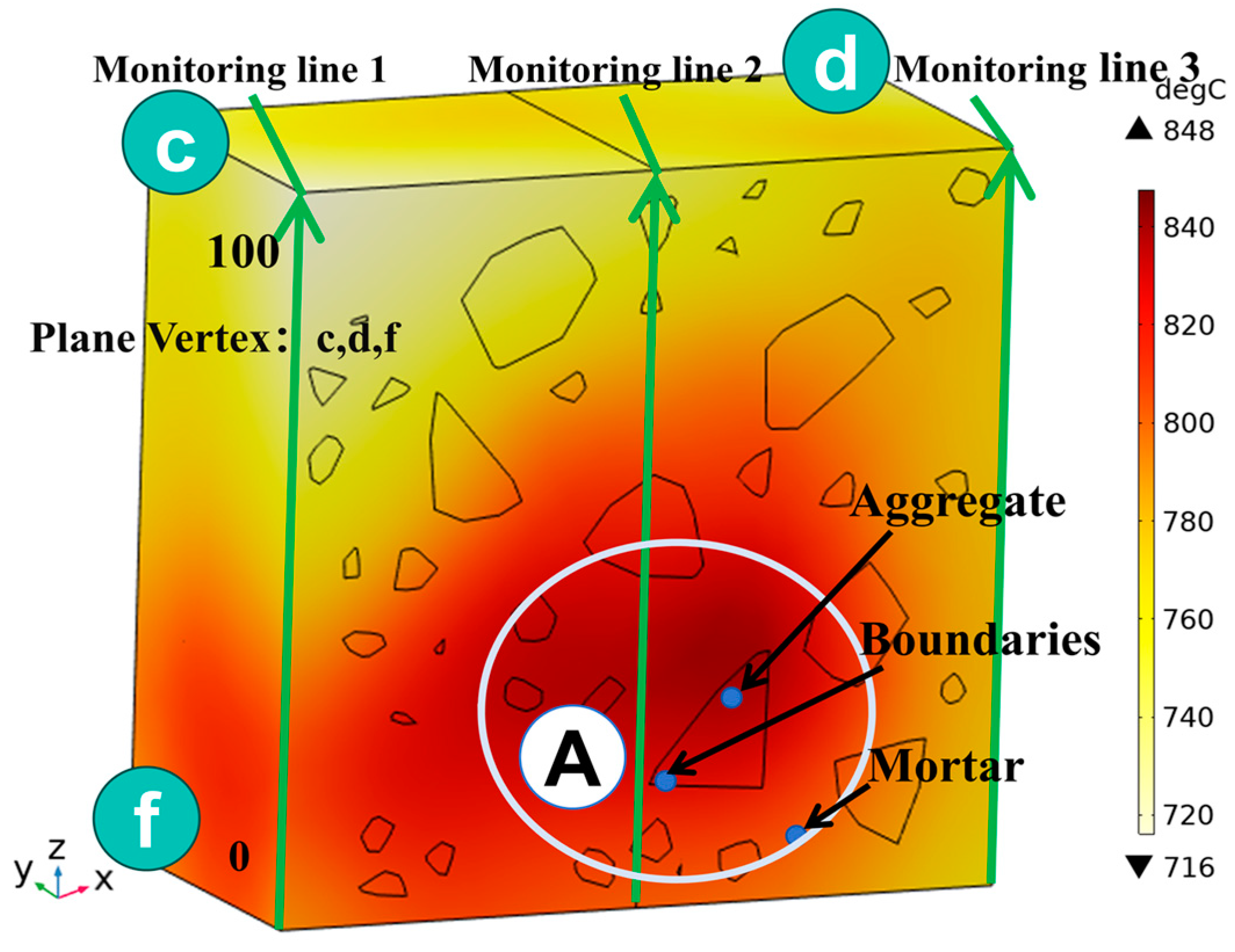
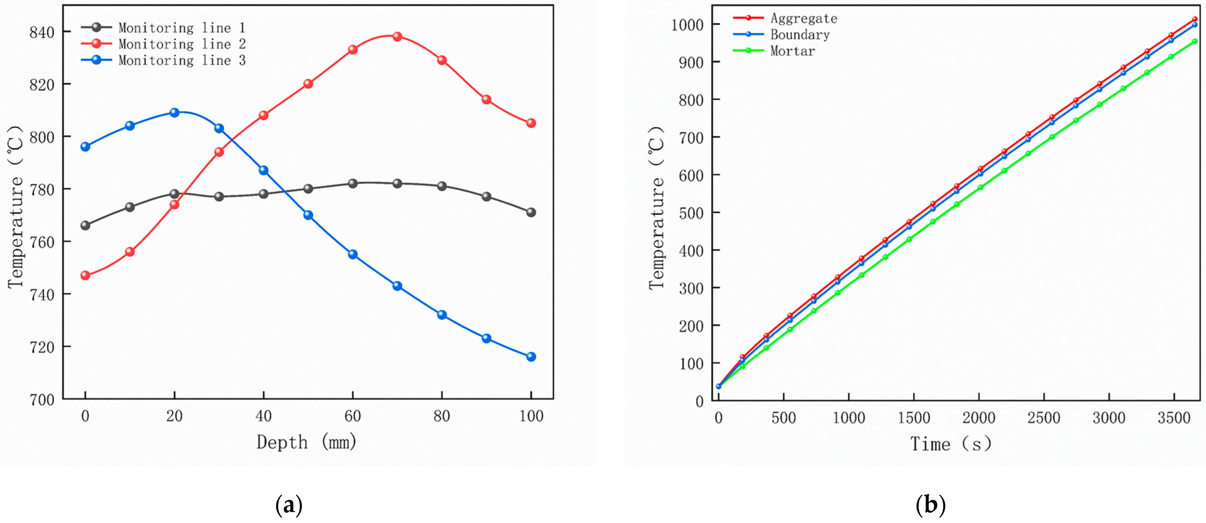
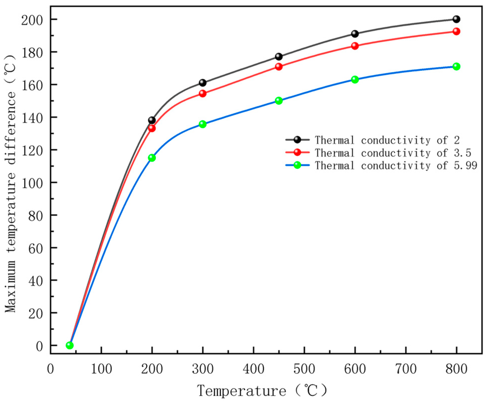
3.2. Electromagnetic Thermal Effects
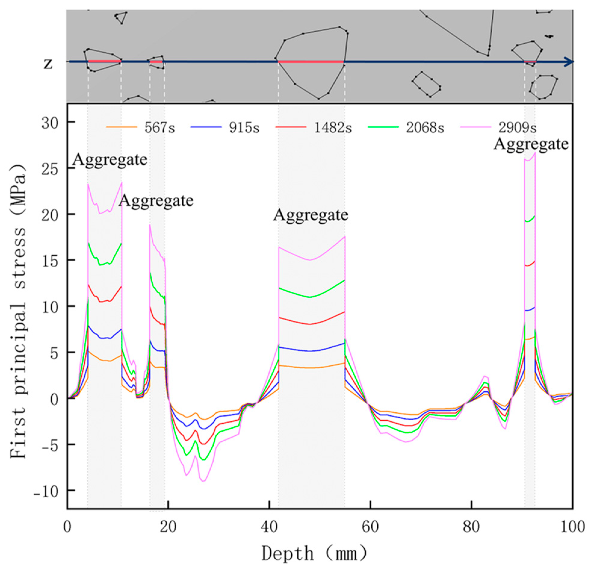
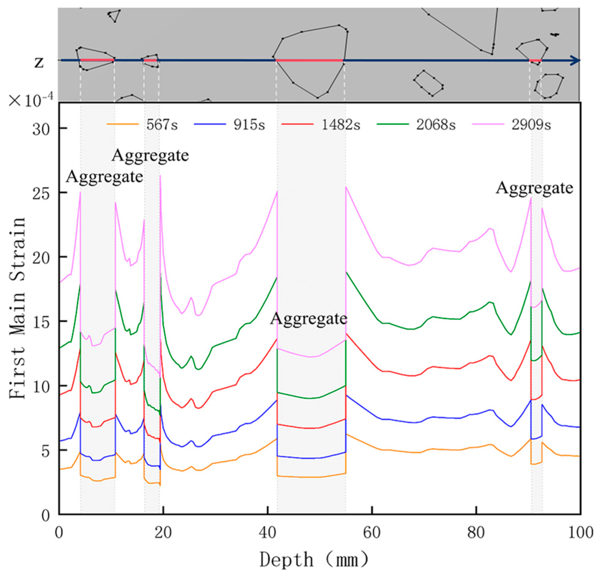
3.3. Thermal Stress Evolution
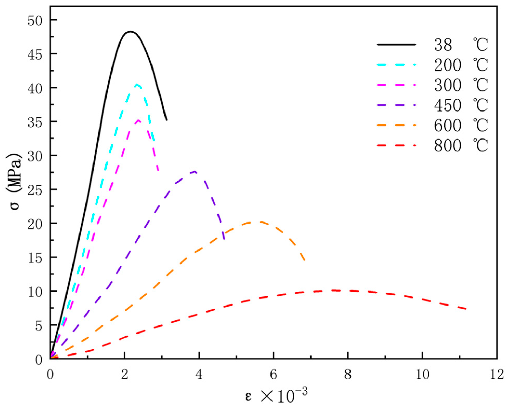
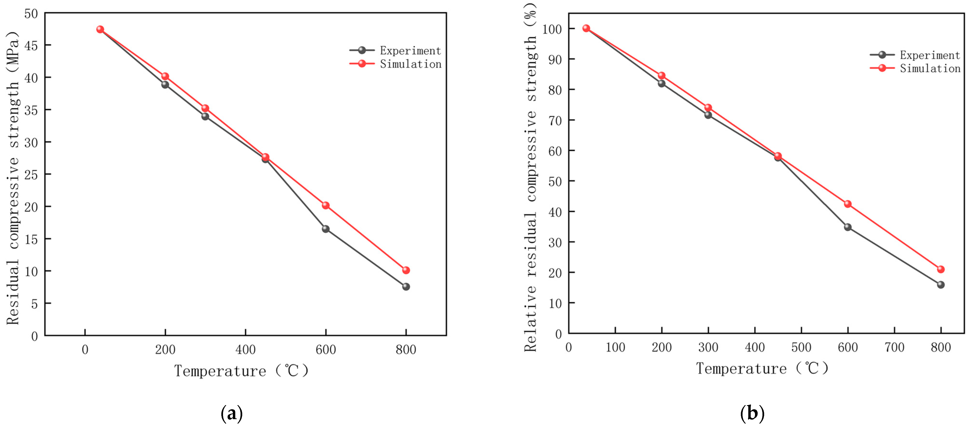
3.4. Compressive Strength Analysis
4. Discussion
4.1. Analysis of Study Results and Limitations
4.2. Research Contributions and Application Discussions
5. Conclusions
Author Contributions
Funding
Institutional Review Board Statement
Informed Consent Statement
Data Availability Statement
Acknowledgments
Conflicts of Interest
References
- Akkurt, I.; Basyigit, C.; Kilincarslan, S.; Mavi, B.; Akkurt, A. Radiation Shielding of Concretes Containing Different Aggregates. Cem. Concr. Compos. 2006, 28, 153–157. [Google Scholar] [CrossRef]
- Golewski, G.L. Determination of Fracture Mechanic Parameters of Concretes Based on Cement Matrix Enhanced by Fly Ash and Nano-Silica. Materials 2024, 17, 4230. [Google Scholar] [CrossRef] [PubMed]
- Shao, Z.; Wang, W.; Zhao, D.; Yuan, Y.; Guo, X. Influence of Adhesive Mortar on the Strength of Recycled Concrete Coarse Aggregate Under Microwave Irradiation. J. Mater. Sci. Eng. 2021, 39, 1–10. [Google Scholar] [CrossRef]
- Luo, L.; Chen, Z.; Cai, S.; Tao, Q.; Xie, L.; Jin, D. Mechanics, γ-Ray Shielding Properties and Acoustic Emission Characteristics of Radiation Shielding Concrete Exposed to Elevated Temperatures. Case Stud. Constr. Mater. 2023, 19, e02572. [Google Scholar] [CrossRef]
- Chen, Z.; Li, Y.; Wu, Q.; Luo, L.; Xie, L.; Deng, D.; Wu, D. The Radiation Protection and High Temperature Performance of Serpentine-Magnetite Mixed Concrete. Case Stud. Constr. Mater. 2024, 20, e03376. [Google Scholar] [CrossRef]
- Fillmore, D.L. Literature Review of the Effects of Radiation and Temperature on the Aging of Concrete; U.S. Department of Energy: Washington, DC, USA, 2004.
- Lee, S.Y.; Dougherty, A.M.; Broton, D.J. Assessing Aggregates for Radiation-Shielding Concrete; U.S. Department of Energy: Washington, DC, USA, 2013.
- Guo, W.; Shi, J.; Zeng, S.; Chen, Z.; Song, X. Different Concrete Aggregate Anti-Radiation Shielding Performance Test. Concrete 2016, 8, 22–26. [Google Scholar] [CrossRef]
- Gencel, O.; Bozkurt, A.; Kam, E.; Korkut, T. Determination and Calculation of Gamma and Neutron Shielding Characteristics of Concretes Containing Different Hematite Proportions. Ann. Nucl. Energy 2011, 38, 2719–2723. [Google Scholar] [CrossRef]
- Gunoglu, K.; Akkurt, İ. Radiation Shielding Properties of Concrete Containing Magnetite. Prog. Nucl. Energy 2021, 137, 103776. [Google Scholar] [CrossRef]
- Lee, C.-M.; Lee, Y.H.; Lee, K.J. Cracking Effect on Gamma-Ray Shielding Performance in Concrete Structure. Prog. Nucl. Energy 2007, 49, 303–312. [Google Scholar] [CrossRef]
- Zhao, D.; Li, H.; Hao, T.; Liu, M. Meso-Microstructure Evolution Mechanism and Residual Strength Tests of High-Strength Concrete after High Temperature. J. Vib. Shock 2023, 42, 1–10. [Google Scholar] [CrossRef]
- Yang, B.; Yang, Y.; Huang, H.; Han, Z.; Peng, F.; Qian, Y.; Shi, Y.; Wu, Z. Research Status of Microwave Heating Performance Optimization; Springer: Berlin, Germany, 2024. [Google Scholar]
- Zhang, X.; Wang, X.; Xu, X.; Zhao, Y. Microwave Curing Process and Mechanical Properties Study of Epoxy Mortars for Repairing Concrete Pavement Rapidly. J. Reinf. Plast. Compos. 2017, 36, 443–451. [Google Scholar] [CrossRef]
- Zheng, Y.; Su, Z.; Fu, H.; Zhang, Q.; Li, J. Thermal Behaviors of Cement and Mortar under Microwave Treatment and the Influencing Factors: An Experimental Study. Constr. Build. Mater. 2024, 411, 134191. [Google Scholar] [CrossRef]
- Akbarnezhad, A.; Ong, K.C.G.; Zhang, M.H.; Tam, C.T.; Foo, T.W.J. Microwave-Assisted Beneficiation of Recycled Concrete Aggregates. Constr. Build. Mater. 2011, 25, 3469–3479. [Google Scholar] [CrossRef]
- Choi, H.; Lim, M.; Choi, H.; Kitagaki, R.; Noguchi, T. Using Microwave Heating to Completely Recycle Concrete. J. Environ. Prot. 2014, 5, 583–596. [Google Scholar] [CrossRef]
- Ouda, A.S. Development of High-Performance Heavy Density Concrete Using Different Aggregates for Gamma-Ray Shielding. HBRC J. 2015, 11, 328–338. [Google Scholar] [CrossRef]
- Dai, J.; Qin, L.-K. Meso-Simulation of Rock Damage under Microwave Irradiation; Springer: Berlin, Germany, 2014. [Google Scholar]
- Liu, Z.; Gan, D.; Gan, Z. Experimental Research on the Dynamic Mechanical Properties and Breakage Behaviors of Magnetite Caused by Microwave Irradiation. Chin. J. Rock Mech. Eng. 2021, 40, 126–136. [Google Scholar] [CrossRef]
- Sun, D.; Wu, K.; Shi, H.; Zhang, L.; Zhang, L. Effect of Interfacial Transition Zone on the Transport of Sulfate Ions in Concrete. Constr. Build. Mater. 2018, 192, 28–37. [Google Scholar] [CrossRef]
- Lan, W.; Wang, H.; Zhang, X.; Fan, H.; Feng, K.; Liu, Y.; Sun, B. Investigation on the Mechanism of Micro-Cracks Generated by Microwave Heating in Coal and Rock. Energy 2020, 206, 118211. [Google Scholar] [CrossRef]
- Liu, X.; Zhao, Y.; Wei, Z.; Yan, D. Heat Transfer Mechanism of Microwave Heating Asphalt Concrete Based on Multi-Physical Field. J. Cent. South Univ. (Sci. Technol.) 2021, 52, 2321–2331. [Google Scholar] [CrossRef]
- Wang, G.; Radziszewski, P.; Ouellet, J. Particle Modeling Simulation of Thermal Effects on Ore Breakage. Comput. Mater. Sci. 2008, 43, 892–901. [Google Scholar] [CrossRef]
- Deng, Y.; Wang, X.; Chen, L.; Liu, M.; Gao, M.; Zhao, J. A Study on the Heating and Deicing Performance of Microwave-Absorbing Asphalt Mixtures. Materials 2023, 16, 1051. [Google Scholar] [CrossRef] [PubMed]
- Wei, W.; Shao, Z.-S.; Chen, W.-W.; Zhang, P.-J.; Yuan, Y. A Fully Coupled Electromagnetic Irradiation, Heat and Mass Transfer Model of Microwave Heating on Concrete. IEEE Access 2021, 9, 1575–1589. [Google Scholar] [CrossRef]
- Xiao, Y.; Shao, Z. Numerical Analysis of Mortar-Aggregate Separation Induced by Microwave Heating. Int. J. Therm. Sci. 2023, 184, 107957. [Google Scholar] [CrossRef]
- Zhang, P.; Wei, W.; Shao, Z. Multifield Coupling Study on Random Aggregate Concrete under Microwave Irradiation. Constr. Build. Mater. 2022, 318, 126025. [Google Scholar] [CrossRef]
- GB 175-2023; General-Purpose Silicate Cement. National Standardization Administration of the State Administration for Market Regulation: Beijing, China, 2023.
- GB/T 14685-2022; Construction Pebbles and Gravel. National Standardization Administration of the State Administration for Market Regulation: Beijing, China, 2022.
- GB/T 14684-2022; Construction Sand. National Standardization Administration of the State Administration for Market Regulation: Beijing, China, 2022.
- GB/T 34008-2017; Radiation Shielding Concrete. General Administration of Quality Supervision, Inspection and Quarantine of the People’s Republic of China National Standardization Management Committee of China: Beijing, China, 2017.
- GB/T 50081-2019; Standard for Testing Methods for the Physical and Mechanical Properties of Concrete. Ministry of Construction of the People’s Republic of China: Beijing, China, 2019.
- Wang, Z.; Bai, E.; Huang, H.; Wang, T.; Sun, H. Study on the Electromagnetic Property and Microwave Heating Efficiency of Concrete with Magnetite Aggregate. Constr. Build. Mater. 2022, 342, 128080. [Google Scholar] [CrossRef]
- Holcomb, G.R. A Review of the Thermal Expansion of Magnetite. Mater. High Temp. 2019, 36, 232–239. [Google Scholar] [CrossRef]
- Mounanga, P.; Khelidj, A.; Bastian, G. Experimental Study and Modelling Approaches for the Thermal Conductivity Evolution of Hydrating Cement Paste. Adv. Cem. Res. 2004, 16, 95–103. [Google Scholar] [CrossRef]
- Liu, X.; Yuan, Y.; Ye, G.; De Schutter, G. Study on Pore Structure Evolution of High Performance with Elevated Temperatures; Springer: Berlin, Germany, 2007. [Google Scholar]
- Li, J.; Kaunda, R.B.; Arora, S.; Hartlieb, P.; Nelson, P.P. Fully-Coupled Simulations of Thermally-Induced Cracking in Pegmatite Due to Microwave Irradiation. J. Rock Mech. Geotech. Eng. 2019, 11, 242–250. [Google Scholar] [CrossRef]
- Yuan, Y.; Tan, L.; Xu, Y.; Yuan, Y.; Dong, J. Numerical and Experimental Study on Drying Shrinkage-Deformation of Apple Slices during Process of Heat-Mass Transfer. Int. J. Therm. Sci. 2019, 136, 539–548. [Google Scholar] [CrossRef]
- Xiao, Y.; Shao, Z.; Wei, W.; Jiang, Y.; Chai, S.; Zong, Z.; Chen, X. Study on Mechanism of Strength Weakening of Concrete Subjected to Microwaves in Microwave-Assisted Concrete Recycling. Int. J. Heat Mass Transf. 2023, 213, 124353. [Google Scholar] [CrossRef]
- Yang, B.; Li, H.; Wang, Z.; Zhang, J.; Zhang, L. Effects of SMA Filament Surface Nano SiO2 Modification on Interface Bonding Strength of SMA/Epoxy Composites; Springer: Berlin, Germany, 2015. [Google Scholar]
- Luo, L.; Chen, Z.; Tao, Q.; Xie, L.; Jin, D.; Li, Z.; Deng, D. Effects of High Temperatures on the Splitting Tensile Strength and Gamma Ray Shielding Performance of Radiation Shielding Concrete. Constr. Build. Mater. 2022, 343, 127953. [Google Scholar] [CrossRef]


| Typology | CaO | SiO2 | Fe2O3 | Al2O3 | MgO | K2O | Na2O | SO3 |
|---|---|---|---|---|---|---|---|---|
| Cement | 62.05 | 22.51 | 3.30 | 4.33 | 1.49 | 1.28 | 0.96 | 2.02 |
| Magnetite | 3.26 | 7.94 | 78.52 | 5.55 | 2.43 | 0.11 | 0.54 | 0.26 |
| Typology | Particle Size (mm) | Apparent Density (kg/m3) | Moisture Content (%) | Water Absorption (%) | Crushing Value Index (%) |
|---|---|---|---|---|---|
| Magnetite ore | 5–20 | 4415 | 0.1 | 0.3 | 7.1 |
| Magnetite sand | 0–5 | 4545 | 0.1 | 0.7 | — |
| Mesh Diameter (mm) | Sieve Residue Measurement (%) | Cumulative Sieve Residue (%) | Cumulative Screening Range (%) |
|---|---|---|---|
| 19 | 0 | 0 | 0–10 |
| 16 | 30 | 30 | 0–40 |
| 9.5 | 40 | 70 | 40–80 |
| 4.75 | 25 | 95 | 90–100 |
| 2.36 | 3 | 98 | 95–100 |
| Mesh Diameter (mm) | Sieve Residue Measurement (%) | Cumulative Sieve Residue (%) | Cumulative Screening Range (%) |
|---|---|---|---|
| 4.75 | 1 | 1 | 0–10 |
| 2.36 | 12 | 13 | 0–25 |
| 1.18 | 22 | 35 | 10–50 |
| 0.6 | 15 | 50 | 41–70 |
| 0.3 | 25 | 75 | 70–92 |
| 0.15 | 16 | 91 | 90–100 |
| Strength Class | Water-Cement Ratio | Volumetric (kg/m3) | |||
|---|---|---|---|---|---|
| Coarse Aggregate | Fine Aggregate | Cement | Water | ||
| C30 | 0.51 | 1941.8 | 1140.4 | 362.7 | 185 |
| Size (mm3) | Number of Aggregate Vertices | Aggregate Radius (mm) | Volume Fraction (%) | ITZ Thickness (mm) | Minimum Spacing of Aggregates (mm) |
|---|---|---|---|---|---|
| 100 × 100 × 100 | 12 | 0.1–0.3 | 13 | 0.024 | 0.01 |
| 0.3–2.5 | 12 | ||||
| 2.5–4.5 | 25 | ||||
| 4.5–10 | 18 |
| Physical Properties | Air 1 | Mortar | Magnetite |
|---|---|---|---|
| Density (kg/m3) | 1.29 | 2300 | 4480 |
| Relative dielectric constant | 1 | 6.91–0.753j 2 | 9.5–2.38j 3 |
| Relative magnetic permeability | 1 | 1 | 1 |
| Thermal conductivity | - | 0.98 2 | 10 4 |
| Electrical conductivity (S/m) | 0 | 0.98 | 0 |
| Coefficient of thermal expansion (10−6/K) | - | 12 2 | 5.99 5 |
| Modulus of elasticity (109Pa) | - | 25 | 130 |
| Poisson’s ratio | - | 0.2 | 0.26 |
| Unit Parameters | Furnace Chamber and Magnetron | Concrete |
|---|---|---|
| Maximum cell size (mm) | 24.47 | 2.31 |
| Minimum cell size (mm) | 7.342 | 0.279 |
| Maximum cell growth rate | 1.35 | 1.35 |
| Curvature factor | 0.6 | 0.6 |
| Narrow area resolution | 0.5 | 0.5 |
| Temperature (°C) | Experimental Appearance | Thermal Imaging | Simulation |
|---|---|---|---|
| 38 |  |  |  |
| 200 | 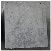 | 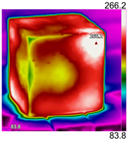 | 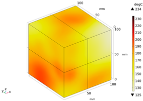 |
| 300 |  | 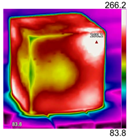 | 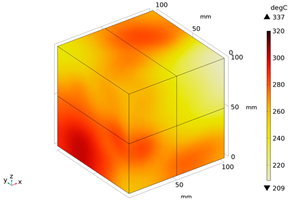 |
| 450 | 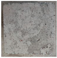 | 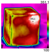 | 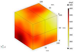 |
| 600 | 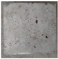 | 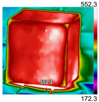 |  |
| 800 | 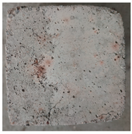 | 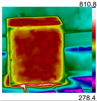 | 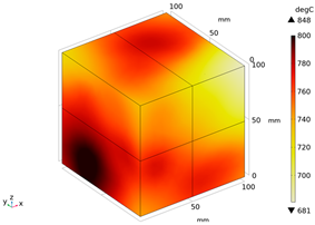 |
| Electromagnetic Distribution | Electric Field Strength (V/m) | Electromagnetic Power Loss (W/m3) |
|---|---|---|
| Body surface | 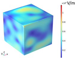 |  |
| XY plane (z = 50 mm) | 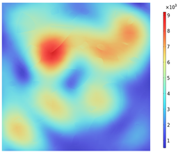 |  |
| YZ plane (x = 50 mm) | 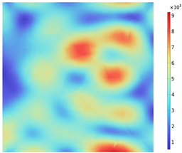 | 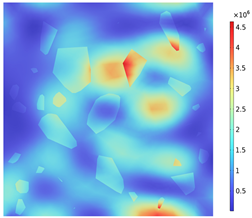 |
| ZX plane (y = 50 mm) | 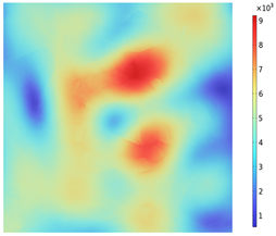 | 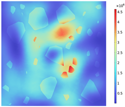 |
| Depth Along z-Axis (mm) | Stress Distribution | Strain Distribution |
|---|---|---|
| 0 | 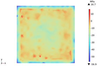 |  |
| 20 | 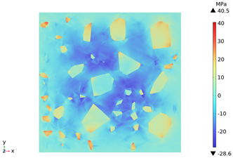 | 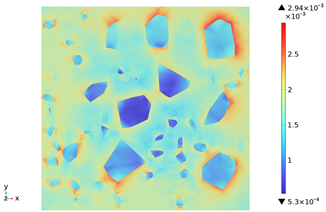 |
| 40 |  | 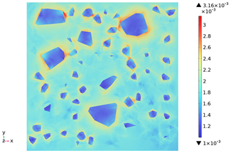 |
| 60 |  | 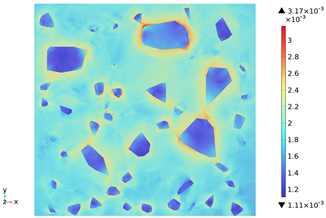 |
| 80 | 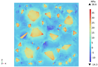 | 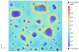 |
| 100 |  |  |
| Temperature (°C) | Residual Compressive Strength (MPa) | Averaged Within the Group (MPa) | ||
|---|---|---|---|---|
| 38 | 47.5 | 48.25 | 46.45 | 47.4 |
| 200 | 35.83 | 38.1 | 37.39 | 38.1 |
| 300 | 33.5 | 33.91 | 32.64 | 33.35 |
| 450 | 26.28 | 26.8 | 27.29 | 26.79 |
| 600 | 16.6 | 16.48 | 15.87 | 16.32 |
| 800 | 7.52 | 7.3 | 7.24 | 7.35 |
| Source of Differences | Sum of Squares of Dispersion | Degree of Freedom | Average Squared | F | Distinctiveness |
|---|---|---|---|---|---|
| Temperature (between groups) | 3213.26 | 5 | 642.65 | 1763.83 | ** |
| Error (within group) | 4.37 | 12 | 0.36 |
| Temperature (°C) | Residual Compressive Strength | Relative Residual Compressive Strength | ||
|---|---|---|---|---|
| Experimental (MPa) | Simulation (MPa) | Experimental (9%) | Simulation (%) | |
| 38 | 47.4 | 47.4 | 100 | 100 |
| 200 | 38.83 | 40.06 | 81.91 | 84.51 |
| 300 | 33.91 | 35.08 | 71.54 | 74.01 |
| 450 | 27.29 | 27.56 | 57.57 | 58.14 |
| 600 | 16.48 | 20.08 | 34.76 | 42.36 |
| 800 | 7.52 | 9.93 | 15.86 | 20.95 |
Disclaimer/Publisher’s Note: The statements, opinions and data contained in all publications are solely those of the individual author(s) and contributor(s) and not of MDPI and/or the editor(s). MDPI and/or the editor(s) disclaim responsibility for any injury to people or property resulting from any ideas, methods, instructions or products referred to in the content. |
© 2025 by the authors. Licensee MDPI, Basel, Switzerland. This article is an open access article distributed under the terms and conditions of the Creative Commons Attribution (CC BY) license (https://creativecommons.org/licenses/by/4.0/).
Share and Cite
Li, G.; Chen, Z.; Wu, Q.; Wu, D.; Tao, Q.; Zou, P.; Liu, Y. Study and Simulation Analysis of Microwave Heating Performance of Magnetite Concrete Based on Random Aggregate Modeling. Materials 2025, 18, 1333. https://doi.org/10.3390/ma18061333
Li G, Chen Z, Wu Q, Wu D, Tao Q, Zou P, Liu Y. Study and Simulation Analysis of Microwave Heating Performance of Magnetite Concrete Based on Random Aggregate Modeling. Materials. 2025; 18(6):1333. https://doi.org/10.3390/ma18061333
Chicago/Turabian StyleLi, Guoyu, Zhenfu Chen, Qiongfang Wu, Dan Wu, Qiuwang Tao, Pinyu Zou, and Yizhi Liu. 2025. "Study and Simulation Analysis of Microwave Heating Performance of Magnetite Concrete Based on Random Aggregate Modeling" Materials 18, no. 6: 1333. https://doi.org/10.3390/ma18061333
APA StyleLi, G., Chen, Z., Wu, Q., Wu, D., Tao, Q., Zou, P., & Liu, Y. (2025). Study and Simulation Analysis of Microwave Heating Performance of Magnetite Concrete Based on Random Aggregate Modeling. Materials, 18(6), 1333. https://doi.org/10.3390/ma18061333