Article

A Study on Hollow Mesoporous Silica Nanoparticles with Long-Term Cycling
1
Department of Nano & Electronic Physics, Kookmin University, Seoul 02707, Republic of Korea
2
Department of Physics, Kookmin University, Seoul 02707, Republic of Korea
*
Author to whom correspondence should be addressed.
Materials 2025, 18(24), 5618; https://doi.org/10.3390/ma18245618
Submission received: 24 October 2025 / Revised: 21 November 2025 / Accepted: 25 November 2025 / Published: 15 December 2025

Abstract

As electronic technologies continue to advance, the demand for high-performance and safe batteries has steadily increased. However, silicon-based anode materials experience severe volume expansion and poor structural stability during cycling, which limits their practical application. In this study, we synthesized hollow mesoporous silica to develop an anode material with long-term cycling stability. Electrochemical analysis revealed that the material exhibited low-capacity decay, decreasing from 125 mA·h·g−1 to 120 mA·h·g−1 at a C-rate of 20 C, and retained a 49 mA·h·g−1 after 500 charge–discharge cycles at a C-rate of 10 C. Furthermore, electrochemical impedance spectroscopy and Scanning Electron Microscopy analysis confirmed that the hollow mesoporous silica structure is long-term cycling stability in the anode.

Graphical Abstract

1. Introduction

Energy storage devices are important components for operating portable electronic equipment such as smartphones, laptops, and smartwatches. As electronic device technologies continue to advance, the demand for high-performance batteries has steadily increased [1,2]. Accordingly, research of and demand for various energy storage systems—including solid-state batteries, solar cells, and lithium-ion batteries—have also grown, highlighting the need for technological innovation and advancement. However, significant safety and stability concerns remain inherent to these devices. In particular, lithium-ion batteries are prone to fires caused by short circuits and overheating due to dendrite formation, which remain among the most critical challenges to overcome [3]. To address these safety issues in high-performance batteries, innovation in battery materials has become an essential research priority.
Meanwhile, a major issue encountered during the charge–discharge processes of high-capacity materials commonly used in secondary batteries, such as Si and Ge, is volume expansion. In the case of Si, the volume expansion can reach up to 300% of the original size, which hinders the formation of a stable solid electrolyte interphase (SEI) layer [4,5]. To address this issue, recent studies have focused on improving the electrochemical performance by synthesizing carbon coatings to ensure mechanical stability against volume expansion, forming core–shell structures, or compositing with carbon nanotubes (CNTs) and graphene [6]. However, these approaches have limitations in fundamentally enhancing the intrinsic stability of high-capacity materials.
A comparison with commonly used anode materials, such as graphite and silicon, can provide a clearer understanding of the advantages and limitations of SiO2. Graphite, a commercialized anode material, has advantage due to its long life cycle, safety, and low cost; however, its primary limitation is a low theoretical capacity of 372 mA·h·g−1. Si anodes have the advantage of a high theoretical capacity 4200 mA·h·g−1, low discharge potential, and abundant resources. SiO2 anodes exhibit smaller volume expansion and better chemical stability than Si. Nevertheless, they have disadvantages such as a lower theoretical capacity of 1965 mA·h·g−1 compared to Si and poor electrical conductivity [7].
In the case of SiO2, various synthesis methods enable the formation of multilayered structures while retaining the intrinsic advantages of the material. Notably, the Stöber method allows facile synthesis of silica with porous or hollow structures [4,8]. Moreover, SiO2 is chemically stable and resistant to side reactions during charge–discharge processes, making it a promising anode active material in terms of stability.
Recent studies have employed compositing and various structural designs to overcome the limitations of the theoretical capacity of SiO2 [8,9]. Among these strategies, mesoporous structures offer advantages in accommodating volume expansion and providing a favorable reaction surface area during charge–discharge cycles. Furthermore, investigations focusing on mesoporous silica structures have demonstrated improved electrochemical properties due to enhanced charge transfer capabilities [10].
In particular, Wang et al. [11] demonstrated that mesoporous structures can significantly enhance electrochemical performance, achieving a capacity of 1060 mA·h·g−1 after 90 cycles at a current density of 100 mA·g−1. Similarly, Peng et al. [12] reported that mesoporous SiOx delivers a capacity of 1434 mA·h·g−1 with 67.5% capacity retention after 500 cycles at 500 mA·g−1, outperforming conventional SiO2. Recent studies have focused on nanoscale silica nanostructures as anode materials, which exhibit superior properties compared to conventional SiO2 nanoparticles. For example, hollow structures synthesized without templates show excellent long-term cycling stability [13]. Additionally, densification of graphite-silica composites via ball milling has been reported to achieve an initial Coulombic efficiency of 73%, a specific capacity of 491.9 mA·h·g−1 at 5 A·g−1, and a stable capacity of 600.3 mA·h·g−1 after 500 cycles at 0.5 A·g−1 [14].
In addition, recent studies have reported that higher stability and efficiency can be achieved by modifying the active material structure, even without a composite. Nan et al. [15] synthesized hollow porous SiO2 nanocubes, which maintained a high reversible capacity of 919 mA·h·g−1 after 30 charge–discharge cycles and maintained 377 mA·h·g−1 after 25 cycles at a high current density of 500 mA·g−1. Miaolun et al. [16] synthesized a hollow SiO2/Carbon composite, which maintains a high reversible capacity of 669.8 mAh·g−1, 98.6% capacity retention, and 99.5% Coulombic efficiency after 100 charge–discharge cycles.
This study is focused on the structural characteristics of HMSNs, which have been previously investigated as drug delivery carriers, to propose the potential application of their hollow mesoporous architecture as an active material for anodes [17]. In addition, considering the structural benefits of the hollow and mesoporous frame works such as enhanced stability during charge–discharge cycling, favorable lithium-ion diffusion, and high electronic conductivity electrochemical properties and EIS analyses for long-term cycling performance are presented.

2. Materials and Methods

2.1. Materials

D-(+)-Glucose (Sigma Aldrich, St. Louis, MO, USA, G5767, ACS reagent) was used as a precursor for the synthesis of carbon nanoparticles. For the silica synthesis, (3-Aminopropyl)triethoxysilane (APTES) (Sigma Aldrich, 440140, 99%) and Tetraethoxysilane (TEOS) (Sigma Aldrich, 131903, 98%) were used. Ammonium hydroxide solution (Samchun Chemical, Seoul, Republic of Korea, 28~30%) was used as a catalyst. Cetrimonium bromide (CTAB) (Sigma Aldrich, H5882, 98%) was used as a synthesis additive. Sodium hydroxide (NaOH) (Sigma Aldrich, 415413, 50% solution in water) was used for pH control. For electrode preparation, Poly(acrylic acid) (PAA) (Sigma Aldrich, 523925, 35 wt% in H2O), Super P (Thermo Fisher Scientific, Waltham, MA, USA, H30253.14, 99+%), lithium chip, a Celgard separator, and an electrolyte (1 M LiPF6 in EC/DEC with 10% FEC additive) were used.

2.2. Synthesis of Carbon Nanoparticles (CNPs)

To synthesize the carbon nanoparticles (CNPs), 12 g of glucose was dissolved in 120 mL of deionized water. The resulting solution was then placed into an autoclave and subjected to hydrothermal treatment at 180 °C for 2 h, with a heating rate of 2 °C/min.

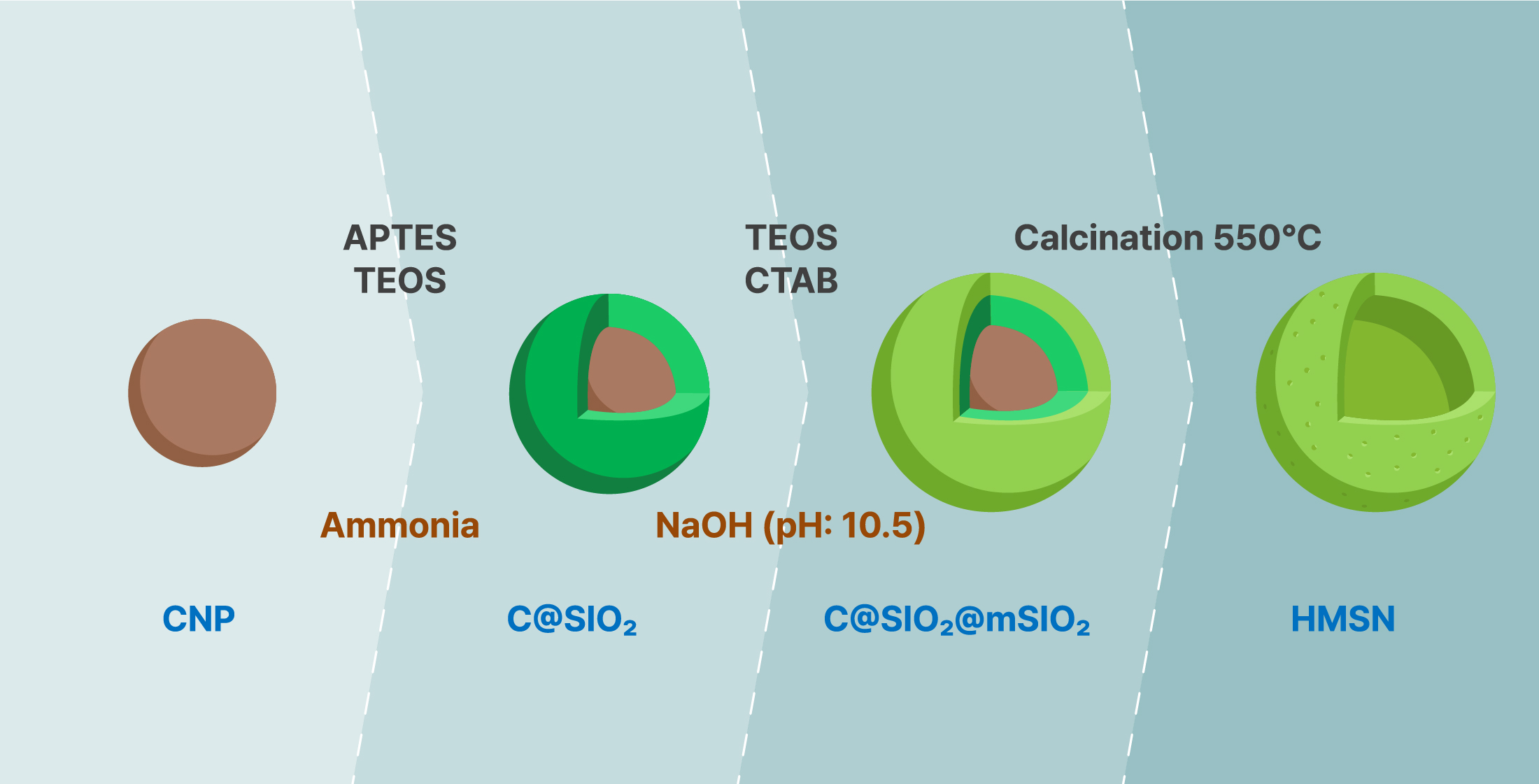
2.3. Synthesis of Hollow Mesoporous Silica Nanoparticles

For the synthesis of HMSNs, 0.05 g of the as-prepared CNPs were dispersed in 20 mL of ethanol, followed by the addition of 85 μL of APTES. After stirring this mixture, 85 μL of TEOS and 250 μL of ammonium hydroxide (NH4OH) were added, and the solution was stirred for 12 h [18,19]. The resulting product was collected by centrifugation, the supernatant was discarded, and the precipitate was redispersed in 6 mL of deionized water via sonication. To this dispersion, 12 mL of additional deionized water, 170 μL of TEOS, and 0.1 mol of CTAB were added and stirred for 10 min to form the mesoporous shell. After adjusting the pH to 10.5–11.5 with NaOH, the reaction was continued at 55 °C for 2 h. The synthesized powder was then washed three times each with deionized water and ethanol and dried in vacuum oven at 60 °C for 24 h. Finally, the HMSNs were obtained by calcining the powder in air at 550 °C for 5 h at a heating rate of 3 °C/min.

2.4. Electrode Preparation

To prepare the anode for the half-cell, a slurry was formed by mixing HMSNs, Super P, and PAA in a weight ratio of 7:2:1 with deionized water. The slurry was then cast onto a copper foil using a doctor blade and dried at 100 °C for 18 h. Galvanostatic charge–discharge profiles, rate capability electrode mass loading 2.12 mg/cm2, cycling performance electrode mass loading 2.20 mg/cm2, electrochemical impedance spectroscopy (EIS) data electrode mass loading 2.12 mg/cm2.

2.5. Characterization

The crystal structure of the synthesized HMSNs was examined by powder X-ray diffraction (XRD; RIGAKU Corporation, Akishima, Tokyo, Japan, Ultima IV) in the 2θ range of 10–60°, using Cu Kα radiation with a characteristic wavelength of 1.5418 Å at a scan rate of 4°/min. The microstructures and compositions of the CNPs and HMSNs were examined using Scanning Electron Microscopy (SEM; HITACHI High-Tech Corporation, Tokyo, Japan, SU8700) and high-resolution transmission electron microscopy (HR-TEM; JEOL Ltd., Akishima, Tokyo, Japan, JEM-3010). Electrochemical performance was evaluated using CR2032 coin-type half-cells. Galvanostatic charge–discharge (GCD) profiles and C-rate capabilities were measured using a battery cycler (Won-A Tech Co., Ltd., Siheung-si, Gyeongggi-do, Republic of Korea, WBCS3000) within a voltage window of 0.05–2.85 V (vs. Li/Li+), where 1C corresponds to a current density of 100 mA·g−1. Cell impedance was analyzed by electrochemical impedance spectroscopy (EIS; IVIUM Technologies B.V., Eindhoven, The Netherlands, Ivium-n-Stat) over a frequency range of 200 kHz to 0.01 Hz, with an applied voltage of 0.01 V and a current of 10 mA.

3. Results

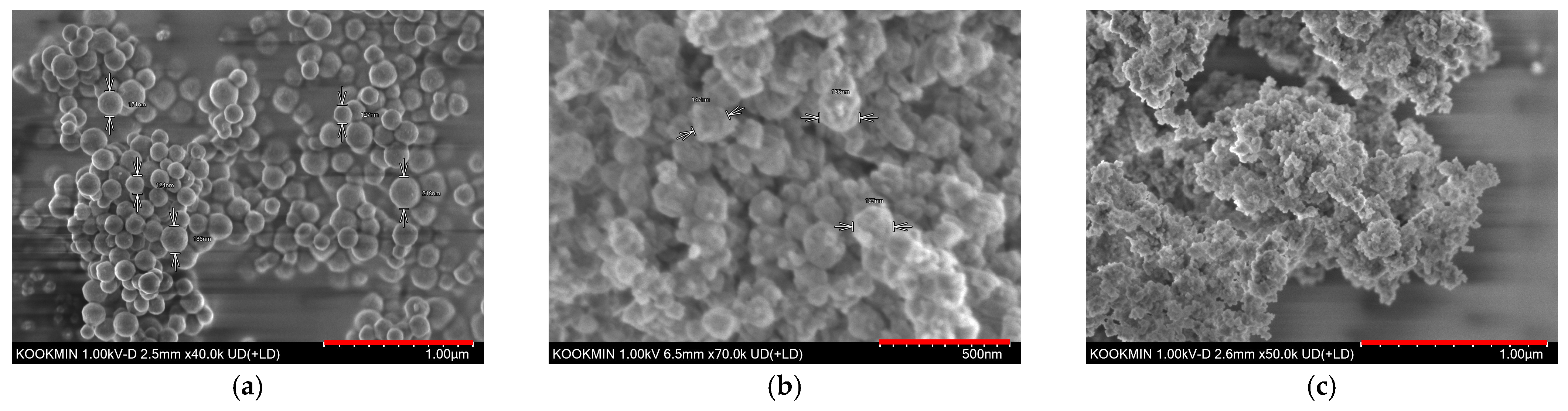
The crystal structure of the HMSNs was analyzed by XRD. In Figure S1, the resulting pattern displayed a broad halo peak around 22.4° which is characteristic of amorphous silica [20]. Figure 1 shows the SEM images of the CNPs synthesized via a hydrothermal method and the HMSNs synthesized via the Stöber method. Figure 1a reveals that the CNP template consists of spherical particles with diameters of approximately 180–200 nm. Figure 1b,c display the SEM images of the HMSNs after calcination at 550 °C and 500 °C, respectively, showing a distinct wrinkled surface morphology. This rough surface suggests the formation of a porous surface, a finding consistent with the work of Xiong et al. [21]. The resulting HMSNs were relatively uniform in size, with diameters of about 190–210 nm. Table 1 presents the EDS data for the samples calcined at 550 °C and 500 °C. A decrease in carbon content of 5.19 wt% was confirmed for the sample calcined at 550 °C.
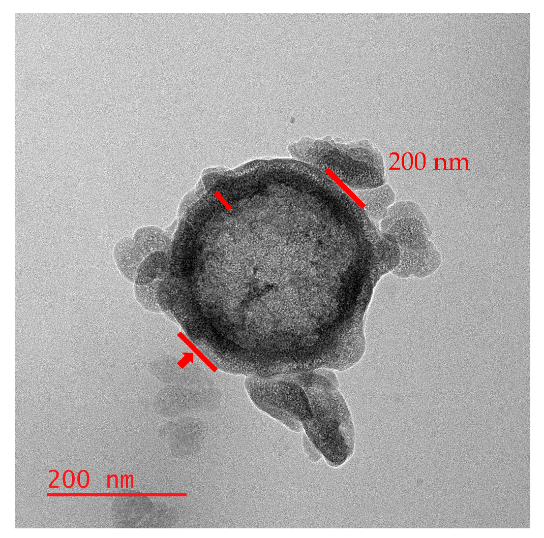
Figure 2 presents the TEM images of the HMSNs synthesized via the Stöber method, which confirm the structure and size of the particles. The images clearly reveal that the synthesized silica possesses a hollow structure [22]. The TEM analysis also reconfirmed that the particles have a diameter of approximately 190–210 nm. As indicated in the images, the silica shell thickness was measured to be around 10–15 nm. Furthermore, the varying contrast in Figure 2 suggests that the particles have a porous surface [23].
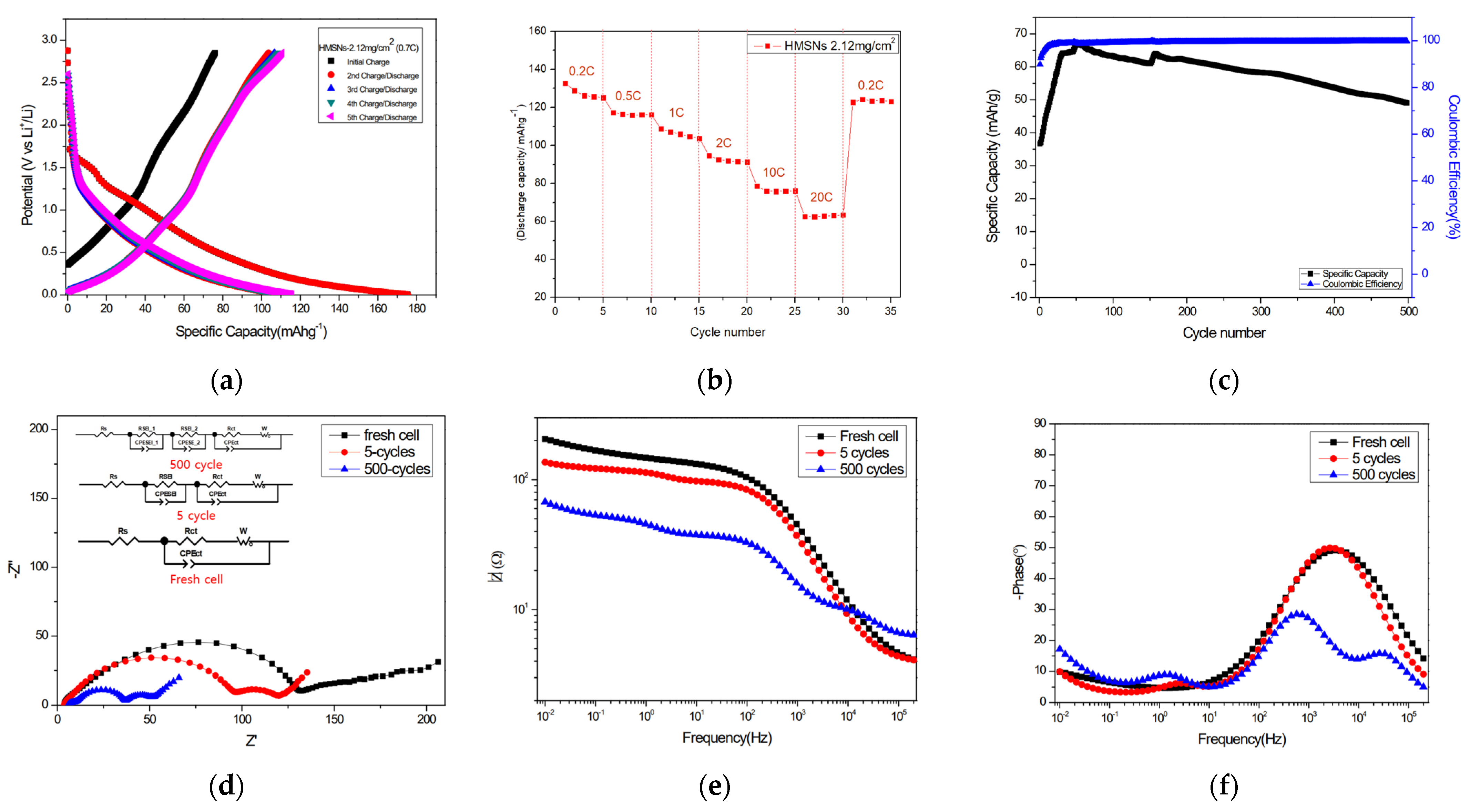
Figure 3 details the electrochemical performance of the HMSN anode in a half-cell configuration, tested within a voltage window of 0.005–2.85 V (vs. Li/Li+) The electrochemical performance was evaluated at a current density corresponding to a C-rate of 100 mA·g−1. Figure 3a presents the GCD profiles for the initial five cycles. Figure 3b illustrates the rate capability of an electrode with a mass loading of 2.12 mg/cm2 at various C-rates from 0.2 C to 20 C. The long-term cycling stability of an electrode with a 0.57 mg/cm2 mass loading is shown in Figure 3c, which was tested at a high rate of 12 C for 1000 cycles.
As shown in the GCD profile in Figure 3a, tested at 0.7 C, the anode delivered a high initial charge capacity of 175 mA·h·g−1. This is followed by a stable charge capacity of 110 mA·h·g−1 from the second to the fifth cycle. The initial discharge capacity was 67 mA·h·g−1. The large irreversible capacity loss after the first cycle is primarily attributed to the formation of a stable SEI layer on the electrode surface [24,25,26]. As shown in Figure 3b, electrode delivered stable capacities of approximately 125–132 mAh·g−1 at 0.2 C 1–5 cycles. The electrode capacity remained 60 mAh·g−1 at a high rate of 20 C. When the C-rate was reverted to 0.2 C, the capacity was approximately 120 mA·h·g−1. It was confirmed that it was similar to the initial 0.2 C capacity.
As shown in Figure 3c, the electrode approaches a capacity of approximately 60 mA·h·g−1 in 55 cycles at a rate of 10 C. It was confirmed that it was similar to the initial capacity. Slight increase in capacity of about 30 mA·h·g−1 from the initial value was observed as cycling progressed. This phenomenon has been reported in the literature. Favors et al. [24] propose a mechanism wherein SiO2 is partially reduced by lithium, leading to the growth of a Si phase. The irreversible formation of Li4SiO4 at the interface therefore creates triply bonded Si (III). The capacity gain associated with this process is greater than the capacity loss from the consumption of SiO [25,27]. The lithiation process of SiO2, the formation of Li4SiO4 and the growth of Si, are described in Equations (1a)–(1c)
S i O 2 + 4 L i + + 4 e S i + 2 L i 2 O
4 L i + + 2 S i O 2 + 4 e L i 4 S i O 4 + S i
x L i + + S i + x e L i x S i
where the capacity slightly decreased during the 500 cycles. The capacity was about 49 mA·h·g−1 at 500 cycles. Nonetheless, the decrease was quite stable in harsh and long-cycled electro-chemical measurements. Also, the Coulombic efficiency reached 99.85% at the 500th cycle, demonstrating the excellent stability of the HMSNs during long-term charge–discharge processes. Figure 3d shows the Nyquist spectra for the anode half-cell at its pristine state (0 cycles), and after 5 and 500 cycles. Notably, the Nyquist plot after 500 cycles reveals the formation of three distinct semicircles, in contrast to the two observed after 5 cycles. This phenomenon is attributed to the formation of a bi-layer SEI on the surface of the porous material [26]. The EIS data were fitted using equivalent circuits. For the fresh cell, where no SEI is formed, the circuit consists only of the solution resistance (Rs), charge transfer resistance (Rct), Warburg impedance (W), and a constant phase element (CPEct). After 5 cycles, an additional parallel circuit of RSEI and CPESEI was introduced to account for the initial formation of the SEI layer. To model the multi-layered structure after 500 cycles, a third semicircle was added, represented by a second RSEI-CPESEI parallel circuit [28]. The fitted resistance values at each cycle, as summarized in Table 2, were as follows: at 0 cycles, Rs = 3.512 Ω and Rct = 122.6 Ω; at 5 cycles, Rs = 3.792 Ω, RSEI = 95.94 Ω, and Rct = 11.2 Ω; and at 500 cycles, Rs = 6.254 Ω, RSEI_1 = 3.496 Ω, RSEI_2 = 27.97 Ω, and Rct = 9.461 Ω. The Rs value shows little change between 0 and 5 cycles but increases by 2.462 Ω after 500 cycles, which is likely due to electrolyte degradation over extended cycling. Conversely, the Rct value decreased as cycling progressed, indicating that ion transfer and electrochemical reactions at the interface became more facile [29]. In Figure 3e, the logarithmic impedance in the high-frequency region increases in the order of the fresh cell, 5-cycle cell, and 500-cycle cell. This region mainly reflects the series resistance (Rs), indicating that the gradual rise in Rs with cycling is associated with electrolyte changes occurring during repeated lithiation and delithiation, thereby revealing progressive cell aging. In contrast, the low-frequency region shows a decreasing trend in the logarithmic impedance from the fresh cell to the 5-cycle and 500-cycle cells. This behavior signifies a reduction in charge-transfer resistance (Rct) as cycling progresses, suggesting that ion-transport resistance at the electrode interface becomes more stabilized during repeated charge–discharge processes. The presence of the first semicircle for the 500-cycle cell in the high-frequency range of the Nyquist plot can be corroborated by the initial slope observed in the 500-cycle spectrum of Figure 3e. Additionally, Figure 3f shows an inflection point near 30,000 Hz, which further supports this feature. For the 500-cycle cell, three downward inflection points appear at approximately 8.8 kHz, 11.9 Hz, and 0.19 Hz, corresponding to the characteristic frequencies of RSEI1, RSEI2, and Rct, respectively. Similarly, in the spectra of the 5cycle and fresh cells, the characteristic frequencies associated with RSEI1 and Rct can be identified at around 8.77 Hz and 0.20 Hz for the 5-cycle cell.
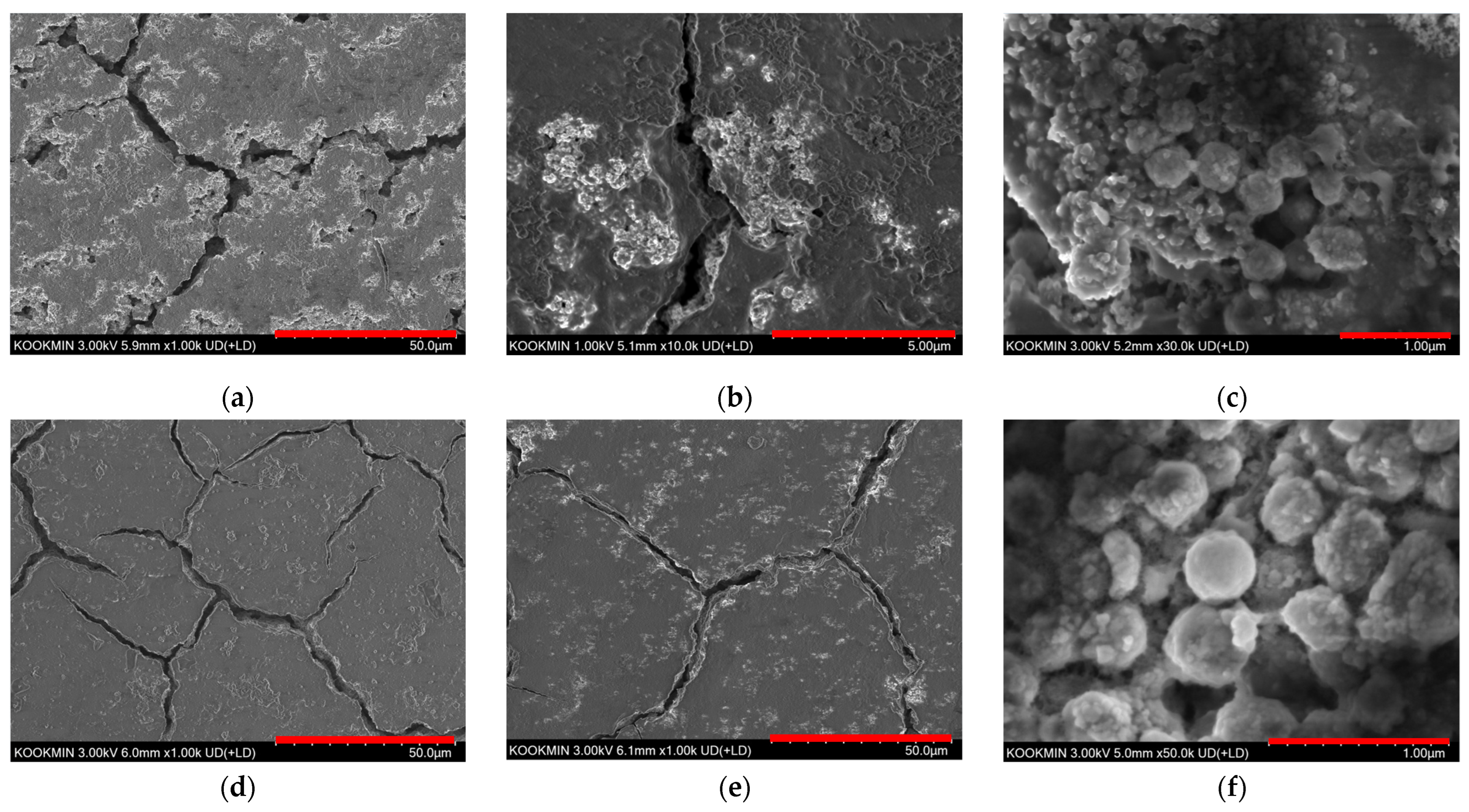
Figure 4a–c display the SEM images of an electrode after 5 cycles at 0.1 C. As shown in Figure 4a,b, a comparison with the pristine HMSN in Figure 1b,c reveals the formation of a thin SEI layer during the initial cycling process. Importantly, the spherical morphology of the HMSNs was well-maintained as seen in Figure 4c. Figure 4d–f show the electrode surface after 500 cycles at a high rate of 10 C. Compared to the 5-cycle electrode, a more uniform and stable SEI layer is evident in Figure 4d,e. Although minor structural alterations to some HMSNs are visible, the majority of particles retained their original shape as seen in Figure 4f. Therefore, the collective EIS and SEM analyses confirm that HMSNs possess outstanding long-term charge–discharge stability.
In this study, HMSNs were synthesized using the Stöber method to be developed as an anode material with long-term cycling stability. Electrochemical analysis of the HMSNs revealed negligible capacity difference at 0.2 C after cycling at 20 C and stably maintained capacity without degradation after 1000 cycles. Furthermore, EIS analysis showed a slight decrease in the Rct value, which indicates that ion transfer and electrochemical reactions remained stable and SEM analysis confirmed the preservation of the particle morphology and the formation of a stable SEI layer. Consequently, these results verify that HMSNs are anode material with exceptional long-term cycling stability.

4. Discussion

When compared with the reference studies summarized in Table 3, the HMSNs exhibit a clear limitation in terms of specific capacity. Nevertheless, after 500 charge–discharge cycles under a high current density of 1 A·g−1, the material maintains a Coulombic efficiency of 99.85%, which exceeds both the current densities and Coulombic efficiencies reported in the cited literature. These results suggest that the intrinsic structural features of the HMSNs contribute substantially to their long-term cycling stability. This observation further implies that other silica-based carriers developed for drug-delivery applications, if they possess comparable structural robustness, may also be repurposed as anode materials for lithium-ion batteries.
Although the present material system still shows limitations in achievable capacity, it appears to have the potential for further improvement through more deliberate tuning of cavity dimensions, shell thickness, and mesopore size, as well as through composite strategies incorporating carbonaceous components. From this perspective, HMSN-based architectures represent a promising platform that could be further advanced through future structural and compositional design efforts aimed at enhancing overall electrochemical performance.

5. Conclusions

In this study, HMSNs was synthesized using the Stöber method to be developed as an anode material with long-term cycling stability. The electrochemical analysis of the HMSNs revealed stable charge–discharge performance at high current conditions, as indicated by the low-capacity decay, decreasing from 125 mA·h·g−1 to 120 mA·h·g−1 at 0.2 C after cycling at 20 C. The electrode also exhibited stable performance at high rates, reaching a capacity of approximately 60 mA·h·g−1 after 55 cycles at 10 C, demonstrating excellent long-term cycling stability. EIS analysis and post-cycling SEM confirmed the formation of a stable SEI and the preservation of the particle morphology. This indicates that the material undergoes stable electrochemical cycling without structural deformation. Therefore, it was confirmed that HMSNs are anode materials with exceptional long-term cycling stability.

Supplementary Materials

The following supporting information can be downloaded at https://www.mdpi.com/article/10.3390/ma18245618/s1, Figure S1. X-ray diffraction (XRD) data of HMSNs.

Author Contributions

Conceptualization, M.s.K.; methodology, M.s.K.; validation, M.s.K., J.h.L. and I.-B.S.; formal analysis, M.s.K. and J.h.L.; investigation, M.s.K. and J.h.L.; resources, I.-B.S.; data curation, M.s.K. and J.h.L.; writing—original draft preparation, M.s.K. and J.h.L.; writing—review and editing, M.s.K., J.h.L. and I.-B.S.; visualization, M.s.K. and J.h.L.; supervision, I.-B.S.; project administration, I.-B.S.; funding acquisition, I.-B.S. All authors have read and agreed to the published version of the manuscript.

Funding

This work was jointly supported by the Next-Generation Communications Program of the Ministry of Science and ICT (MSIT) (No. 2024-A2024-0197); the 2023–2024 Innovative Convergence University Program for Advanced Fields (Next-Generation Communications)—Research & Education Model (Content) Development Project; and the 2023–2024 WE-MEET Program.

Institutional Review Board Statement

Not applicable.

Data Availability Statement

The original contributions presented in this study are included in the article/Supplementary Materials. Further inquiries can be directed to the corresponding author.

Conflicts of Interest

The authors declare no conflicts of interest.

Abbreviations

EISElectrochemical Impedance Spectroscopy
SEMScanning Electron Microscopy
ECethylene carbonate
LIBLithium-Ion Battery
HMSNsHollow Mesoporous Silica Nanoparticles
APTES(3-Aminopropyl)triethoxysilane
CTABCetrimonium bromide
NaOHSodium hydroxide
PAAPoly(acrylic acid)
CNPscarbon nanoparticles
GCDGalvanostatic charge–discharge
SEISolid Electrolyte Interphase
TEMhigh-resolution transmission electron microscopy
CNTscarbon nanotubes

References

  1. Tarascon, J.-M.; Armand, M. Issues and challenges facing rechargeable lithium batteries. Nature 2001, 414, 359–367. [Google Scholar] [CrossRef] [PubMed]
  2. Armand, M.; Tarascon, J.-M. Building better batteries. Nature 2008, 451, 652–657. [Google Scholar] [CrossRef]
  3. Kim, S.; Song, J.; Lee, H.; Jung, S.; Park, J.; Lee, H.; Lee, Y.M. Simulation Study on Internal Short Circuits in a Li-Ion Battery Depending on the Sizes, Quantities, and Locations of Li Dendrites. Front. Mater. 2022, 9, 850610. [Google Scholar] [CrossRef]
  4. Zhu, G.; Chao, D.; Xu, W.; Wu, M.; Zhang, H. Microscale Silicon-Based Anodes: Fundamental Understanding and Industrial Prospects for Practical High-Energy Lithium-Ion Batteries. ACS Nano 2021, 15, 15567. [Google Scholar] [CrossRef]
  5. Kong, X.; Xi, Z.; Wang, L.; Zhou, Y.; Liu, Y.; Wang, L.; Li, S.; Chen, X.; Wan, Z. Recent Progress in Silicon−Based Materials for Performance−Enhanced Lithium−Ion Batteries. Molecules 2023, 28, 2079. [Google Scholar] [CrossRef] [PubMed]
  6. He, S.; Huang, S.; Wang, S.; Mizota, I.; Liu, X.; Hou, X. Considering Critical Factors of Silicon/Graphite Anode Materials for Practical High-Energy Lithium-Ion Battery Applications. Energy Fuels 2020, 35, 944. [Google Scholar] [CrossRef]
  7. Jiao, M.; Liu, K.C.; Shi, Z.; Wang, C. SiO2/Carbon Composite Microspheres with Hollow Core–Shell Structure as a High-Stability Electrode for Lithium-Ion Batteries. ChemElectroChem 2017, 4, 542–549. [Google Scholar] [CrossRef]
  8. Al Ja’farawy, M.S.; Hikmah, D.N.; Riyadi, U.; Purwanto, A.; Widiyandari, H. A Review: The Development of SiO2/C Anode Materials for Lithium-Ion Batteries. J. Electron. Mater. 2021, 50, 6667. [Google Scholar] [CrossRef]
  9. Buga, M.; Spinu-Zaulet, A.A.; Ungureanu, C.G.; Mitran, R.; Vasile, E.; Florea, M.; Neatu, F. Carbon-Coated SiO2 Composites as Promising Anode Material for Li-Ion Batteries. Molecules 2021, 26, 4531. [Google Scholar] [CrossRef]
  10. Walcarius, A. Mesoporous materials and electrochemistry. Chem. Soc. Rev. 2013, 42, 4098–4140. [Google Scholar] [CrossRef]
  11. Wang, Y.; Xie, K.; Guo, X.; Zhou, W.; Song, G.; Cheng, S. Mesoporous silica nanoparticles as high performance anode materials for lithium-ion batteries. New J. Chem. 2016, 40, 8202. [Google Scholar] [CrossRef]
  12. Peng, J.; Luo, J.; Li, W.; Zeng, P.; Wu, Z.; Wang, Y.; Li, J.; Shu, H.; Wang, X. Insight into the performance of the mesoporous structure SiOx nanoparticles anchored on carbon fibers as anode material of lithium-ion batteries. J. Electroanal. Chem. 2020, 880, 114798. [Google Scholar] [CrossRef]
  13. Zhou, X.; Liu, Y.; Ren, Y.; Mu, T.; Yin, X.; Du, C.; Huo, H.; Cheng, X.; Zuo, P.; Yin, G. Engineering Molecular Polymerization for Template-Free SiOx/C Hollow Spheres as Ultrastable Anodes in Lithium-Ion Batteries. Adv. Funct. Mater. 2021, 31, 2101145. [Google Scholar] [CrossRef]
  14. Xie, H.; Hou, C.; Qu, Y.; Tian, H.; Lu, H.; Wu, J.; Yang, S.; Ma, Y. N-SiO/graphite/rGO-CNTs@C composite with dense structure for high performance lithium-ion battery anode. J. Energy Storage 2023, 72, 108452. [Google Scholar] [CrossRef]
  15. Yan, N.; Wang, F.; Zhong, H.; Li, Y.; Wang, Y.; Hu, L.; Chen, Q. Hollow Porous SiO2 Nanocubes Towards High-performance Anodes for Lithium-ion Batteries. Sci. Rep. 2013, 3, 1568. [Google Scholar] [CrossRef] [PubMed]
  16. Zafar Abbas Manj, R.; Zhang, F.; Ur Rehman, W.; Luo, W.; Yang, J. Toward understanding the interaction within Silicon-based anodes for stable lithium storage. Chem. Eng. J. 2020, 385, 123821. [Google Scholar] [CrossRef]
  17. Zhang, H.; Xu, H.; Wu, M.; Zhong, Y.; Wang, D.; Jiao, Z. A Soft–Hard Template Approach towards Hollow Mesoporous Silica Nanoparticles with Rough Surfaces for Controlled Drug Delivery and Protein Adsorption. J. Mater. Chem. B 2015, 3, 6480–6489. [Google Scholar] [CrossRef]
  18. Jiang, X.; Tang, X.; Tang, L.; Zhang, B.; Mao, H. Synthesis and formation mechanism of amorphous silica particles via sol–gel process with tetraethylorthosilicate. Ceram. Int. 2019, 45, 7673–7680. [Google Scholar] [CrossRef]
  19. Gulavani, V.; Thotiyl, M.O.; John, B.; Yengantiwar, A. Post-mortem study and long cycling stability of silica/carbon composite as anode in Li-ion cells. J. Phys. D Appl. Phys. 2024, 57, 415501. [Google Scholar] [CrossRef]
  20. Cao, X.X.; Chuan, X.; Li, S.G.; Huang, D.; Cao, G. Hollow Silica Spheres Embedded in a Porous Carbon Matrix and Its Superior Performance as the Anode for Lithium-Ion Batteries. Part. Part. Syst. Charact. 2016, 33, 110–117. [Google Scholar] [CrossRef]
  21. Xiong, J.; Duan, N.; Lu, C.; Zhang, Y.; Li, C.; Peng, S.; Lai, Y.; Hu, K. Influence of SiO2 size effect on multi-scale micro-nanostructure superhydrophobic Al2O3 ceramic membrane: Preparation, mechanism, application. J. Water Process Eng. 2024, 59, 105020. [Google Scholar] [CrossRef]
  22. Chen, F.; Hong, H.; Shi, S.; Goel, S.; Valdovinos, H.F.; Hernandez, R.; Theuer, C.P.; Barnhart, T.E.; Cai, W. Engineering of Hollow Mesoporous Silica Nanoparticles for Remarkably Enhanced Tumor Active Targeting Efficacy. Sci. Rep. 2014, 4, 5080. [Google Scholar] [CrossRef]
  23. Gao, P.; Huang, X.; Zhao, Y.; Hu, X.; Cen, D.; Gao, G.; Bao, Z.; Mei, Y.; Di, Z.; Wu, G. Formation of Si Hollow Structures as Promising Anode Materials through Reduction of Silica in AlCl3–NaCl Molten Salt. ACS Nano 2018, 12, 11481–11490. [Google Scholar] [CrossRef] [PubMed]
  24. Wu, H.; Yu, G.; Pan, L.; Liu, N.; Mcdowell, M.T.; Bao, Z.; Cui, Y. Stable Li-ion battery anodes by in-situ polymerization of conducting hydrogel to conformally coat silicon nanoparticles. Nat. Commun. 2013, 4, 1943. [Google Scholar] [CrossRef] [PubMed]
  25. Favors, Z.; Wang, W.; Bay, H.H.; George, A.; Ozkan, M.; Ozkan, C.S. Stable Cycling of SiO2 Nanotubes as High-Performance Anodes for Lithium-Ion Batteries. Sci. Rep. 2014, 4, 4605. [Google Scholar] [CrossRef]
  26. Wang, A.; Kadam, S.; Li, H.; Shi, S.; Qi, Y. Review on modeling of the anode solid electrolyte interphase (SEI) for lithium-ion batteries. NPJ Comput. Mater. 2018, 4, 15. [Google Scholar] [CrossRef]
  27. Ban, C.; Kappes, B.B.; Xu, Q.; Engtrakul, C.; Ciobanu, C.V.; Dillon, A.C.; Zhao, Y. Lithiation of silica through partial reduction. Appl. Phys. Lett. 2012, 100, 243905. [Google Scholar] [CrossRef]
  28. Wu, B.; Chen, C.; Danilov, D.L.; Jiang, M.; Raijmakers, L.H.J.; Eichel, N.A.; Notten, P.H.L. Influence of the SEI Formation on the Stability and Lithium Diffusion in Si Electrodes. ACS Omega 2022, 7, 32740–32748. [Google Scholar] [CrossRef] [PubMed]
  29. Choi, W.; Shin, H.; Kim, J.M.; Choi, J.; Yoon, W. Modeling and Applications of Electrochemical Impedance Spectroscopy (EIS) for Lithium-ion Batteries. J. Electrochem. Sci. Technol. 2020, 11, 1–13. [Google Scholar] [CrossRef]
Figure 1. (a) SEM image of CNPs synthesized via the hydrothermal method. (b) SEM image of HMSNs after 550 °C calcination. (c) SEM image of HMSNs after 500 °C.
Materials 18 05618 g001
Figure 2. TEM images of the HMSNs after calcination.
Materials 18 05618 g002
Figure 3. Lithium storage measurement of SiO2 in a half cell. (a) Galvanostatic charge–discharge profiles, (b) rate capability, (c) cycling performance, (d) Nyquist plot, (e) bode-mode plots, (f) Bode-phase plots.
Materials 18 05618 g003
Figure 4. SEM images of the electrode after cycles. (ac) After 5 cycles at 0.1 C, and (df) after 500 cycles at 10 C.
Materials 18 05618 g004
Table 1. EDS data of HMSNs calcined at 500 °C and 550 °C.
Element500 °C (wt%/Atomic%)550 °C (wt%/Atomic%)
C10.01/15.904.82/8.07
O44.82/53.4344.20/55.49
Si45.17/30.6750.97/36.45
Table 2. Fitted resistance parameters from EIS data at different cycle numbers.
Rs (Ω)Rct (Ω)RSEI (Ω)CPESEI (F)CPEct (F)
Fresh cell3.512122.6--0.7227
5 cycle3.79211.295.940.771.15
500 cycle6.2649.4613.496/27.970.999/0.83721.013
Table 3. Variation in electrochemical performance of SiO2 materials.
AnodeCurrent Density (mA·g−1)Initial CE (%)Reversible Capacity (mA·h·g−1)After nth Cycle (Cycle)Reference
Mesoporous SiO2 nanoparticles10017.4106090[11]
m-SiOx/C30066.8613200[12]
Hollow porous SiO2 nanocubes1004791930[15]
Hollow SiO2/carbon10048.2649.6160[16]
HMSNs120043.4801000
Disclaimer/Publisher’s Note: The statements, opinions and data contained in all publications are solely those of the individual author(s) and contributor(s) and not of MDPI and/or the editor(s). MDPI and/or the editor(s) disclaim responsibility for any injury to people or property resulting from any ideas, methods, instructions or products referred to in the content.