
Investigation of the Effect of the Shape of Cutting Knives Limiting Burr in High-Strength Multiphase Steel Sheets

 ,
,  ,
,  ,
,
Abstract
1. Introduction
2. Materials and Methods
3. Results and Discussion
3.1. Results of Theoretical Analysis of the Sheet Metal Cutting Process
3.2. Experimental Analysis of the Sheet Metal Cutting Process
4. Conclusions
Author Contributions
Funding
Institutional Review Board Statement
Informed Consent Statement
Data Availability Statement
Conflicts of Interest
References
- Galán, J.; Samek, L.; Verleysen, P.; Verbeken, K.; Houbaert, Y. Advanced high strength steels for automotive industry. Rev. Metal. 2012, 48, 118–131. [Google Scholar] [CrossRef]
- Skowronek, A.; Grajcar, A.; Petrov, R.H. Dependence of mechanical properties on the phase composition of intercritically annealed medium-Mn steel as the main competitor of high-strength DP steels. Sci. Rep. 2024, 14, 9567. [Google Scholar] [CrossRef] [PubMed]
- Mehdi, Y.; Tisza, M. Formability Investigations of Advanced High Strength Steels. IOP Conf. Ser. Mater. Sci. Eng. 2018, 448, 012022. [Google Scholar] [CrossRef]
- Butuc, M.C.; Vincze, G.; Santos, R.; Pereira, A.; Santos, A.D.; Amaral, R.L.; Barlat, F. Formability of third generation advanced high strength steel: Experimental and theoretical approach. Int. J. Mech. Sci. 2024, 281, 109559. [Google Scholar] [CrossRef]
- Pater, Z.; Samołyk, G. Podstawy Technologii Obróbki Plastycznej Metali; Politechnika Lubelska: Lublin, Poland, 2013. [Google Scholar]
- Bagul, Y.; Mansuri, A. A review on sheet metal cutting/shearing machine. Int. Res. J. Mod. Eng. Technol. Sci. 2022, 4, 802–804. [Google Scholar]
- Vijay, K.; Ketan, D.; Hemant, F.; Ranjit, K.; Roundal, V.B.; Deshpande, S.V. Design of sheet metal profile gas cutting machine by using scrap. Int. J. Innov. Res. Sci. Eng. 2017, 3, 184–190. [Google Scholar]
- Keles, O.; Oner, U. A Study of the Laser Cutting Process: Influence of Laser Power and Cutting Speed on Cut Quality. Lasers Eng. 2010, 20, 319–327. [Google Scholar]
- Magid, H.M. Experimental study of mild steel cutting process by using the plasma arc method. J. Achiev. Mater. Manuf. Eng. 2021, 108, 75–85. [Google Scholar] [CrossRef]
- Mert, T. Water jet cutting technology and its comparison with other cutting methods in some aspects. Acad. J. Sci. 2012, 1, 275–282. [Google Scholar]
- Kaczmarczyk, J. Modelling of Guillotine Cutting of a Cold-Rolled Steel Sheet. Materials 2019, 12, 2954. [Google Scholar] [CrossRef]
- Mamaev, A.; Balabina, T.; Karelina, M. Determining the optimum cut of sheet roll material. E3S Web Conf. 2023, 402, 11023. [Google Scholar] [CrossRef]
- Bohdal, Ł.; Kałduński, P. Analiza numeryczna przyczyn powstawania zadziorów na powierzchni przecięcia blach karoseryjnych podczas cięcia na gilotynie. Autobusy 2012, 5, 44–49. [Google Scholar]
- Murakawa, M.; Maeda, T. A new method of burr-free slitting. J. Mech. Work. Technol. 1979, 2, 101–118. [Google Scholar] [CrossRef]
- Feistlea, M.; Koslowa, I.; Krinningera, M.; Gollea, R.; Volka, W. Reduction of burr formation for conventional shear cutting of boron-alloyed sheets through focused heat treatment. Sci. Direct 2017, 63, 493–498. [Google Scholar] [CrossRef]
- Song, H.; Wu, B. Physics-based modeling and micro-burr removal mechanism analysis for laser-induced plasma deburring. J. Manuf. Process. 2022, 75, 1217–1229. [Google Scholar] [CrossRef]
- Aziz, M.; Ohnishi, O.; Onikura, H. Innovative micro hole machining with minimum burr formation by the use of newly developed micro compound tool. J. Manuf. Process. 2012, 14, 224–232. [Google Scholar] [CrossRef]
- Marciniak, Z. Konstrukcja Wykrojników; WNT: Warszawa, Poland, 1994. [Google Scholar]
- Ghosh, S.; Li, M.; Khadke, A. 3D modeling of shear-slitting process for aluminum alloys. J. Mater. Process. Technol. 2005, 167, 91–102. [Google Scholar] [CrossRef]
- Saanouni, K.; Belamri, N.; Autesserre, P. Finite element simulation of 3D sheet metal guillotining using advanced fully coupled elastoplastic-damage constitutive equations. Finite Elem. Anal. Des. 2010, 46, 535–550. [Google Scholar] [CrossRef]
- Meehan, R.R.; Burns, S.J. Mechanics of slitting and cutting webs. Exp. Mech. 1998, 38, 103–109. [Google Scholar] [CrossRef]
- Bohdal, Ł.; Kukiełka, L. Application of variational and fem methods to the modelling and numerical analysis of the slitting process for geometrical and physical nonlinearity. J. Theor. Appl. Mech. 2015, 53, 487–500. [Google Scholar] [CrossRef]
- Ma, J.; Lu, H.; Li, M.; Wang, B. Burr height in shear slitting of aluminum webs. ASME J. Manuf. Sci. Eng. 2006, 128, 46–55. [Google Scholar] [CrossRef]
- Available online: https://magazynprzemyslowy.pl/artykuly/gladko-bez-zadziorow-technika-gratowania (accessed on 1 December 2024).
- Available online: https://www.arku.com/pl/procedura/gratowanie (accessed on 1 December 2024).
- Available online: https://www.dienesusa.com/ (accessed on 1 December 2024).
- VDA 239-100; Flacherzeugnisse aus Stahl zur Kaltumformung/Sheet Steel for Cold Forming (05/2024)—Gruppenlizenz (Group License), AGB (GTC) Art. 10, 2—Language of the Document German and English online access (05/2024). German Association of the Automotive Industry (VDA): Berlin, Germany, 2024.
- Mróz, S. Proces Walcowania Prętów z Wzdłużnym Rozdzielaniem Pasma; Wydawnictwo Politechniki Częstochowskiej: Częstochowa, Poland, 2008. [Google Scholar]
- Danchenko, V.; Dyja, H.; Lesik, L.; Mashkin, L.; Milenin, A. Technologia i Modelowanie Procesów Walcowania w Wykrojach; Wydawnictwo Politechniki Częstochowskiej: Częstochowa, Poland, 2002. [Google Scholar]
- Hensel, A.; Spittel, T. Kraft und Arbeitsbedarf Bildsomer Formgeburgs; VEB Deutscher Verlang für Grundstoffindustrie: Lipsk, Germany, 1979. [Google Scholar]
- Norton, F.H. Creep of Steel at High Temperature; McGraw Hill: New York, NY, USA, 1929. [Google Scholar]
- Hoff, N.J. Approximate Analysis of Structures in the Presence of Moderately Large Steps Deformation. Quart. Appl. Mech. 1954, 2, 49. [Google Scholar]
- Cockroft, M.; Latham, D. Ductility and the workability of metals. J. Inst. Metals 1968, 96, 33–39. [Google Scholar]


| Chemical Composition, % Mass. | |||||||
|---|---|---|---|---|---|---|---|
| C | Si | Mn | P | S | Al | Cr + Mo | Ti + Nb |
| 0.18 | 1.0 | 2.5 | 0.05 | 0.01 | 0.015–1.0 | 1.0 | 0.15 |
| Ys0.2, MPa | UTS, MPa | YM, GPa | E, % |
|---|---|---|---|
| 570–720 | 780–980 | 208 | 10 |
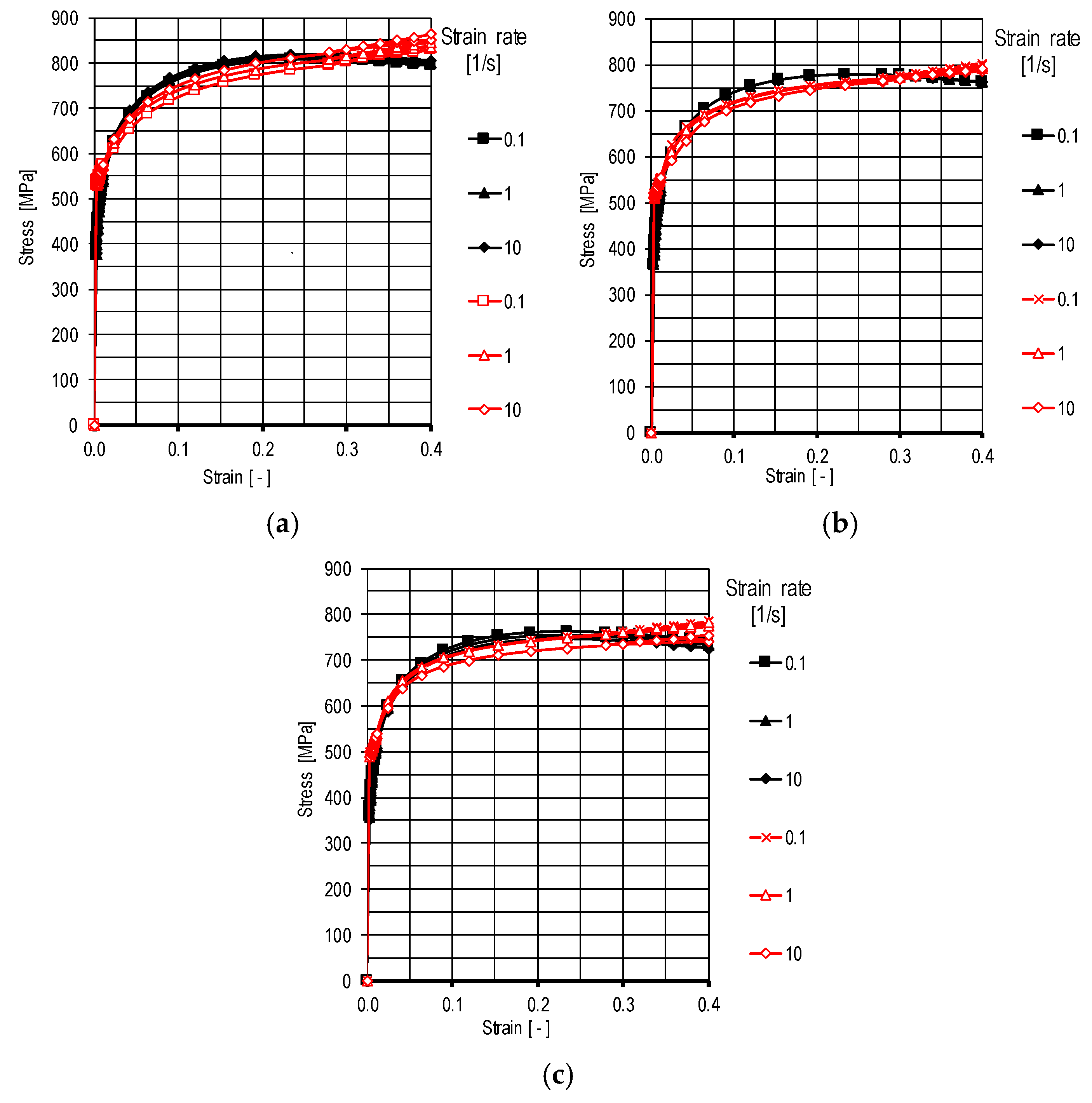
| K | m1 | m2 | m3 | m4 | m5 | m6 | m7 | m8 |
|---|---|---|---|---|---|---|---|---|
| 0.684788 | −0.00721633 | 0.342418 | 0.02864 | −0.00439388 | −0.08198 | 0.000230534 | 0.0002181 | 1.41094 |
| Strain Rate [s−1] | Limit Values of the Normalized Cockroft–Latham Criterion | Absolute Error Δ | Relative Error δ | |
|---|---|---|---|---|
| Notch 5 mm | Notch 8 mm | |||
| 0.1 | 0.518 | 0.521 | 0.009 | 1.74% |
| 1.0 | 0.525 | 0.531 | ||
| 10.0 | 0.539 | 0.537 | ||
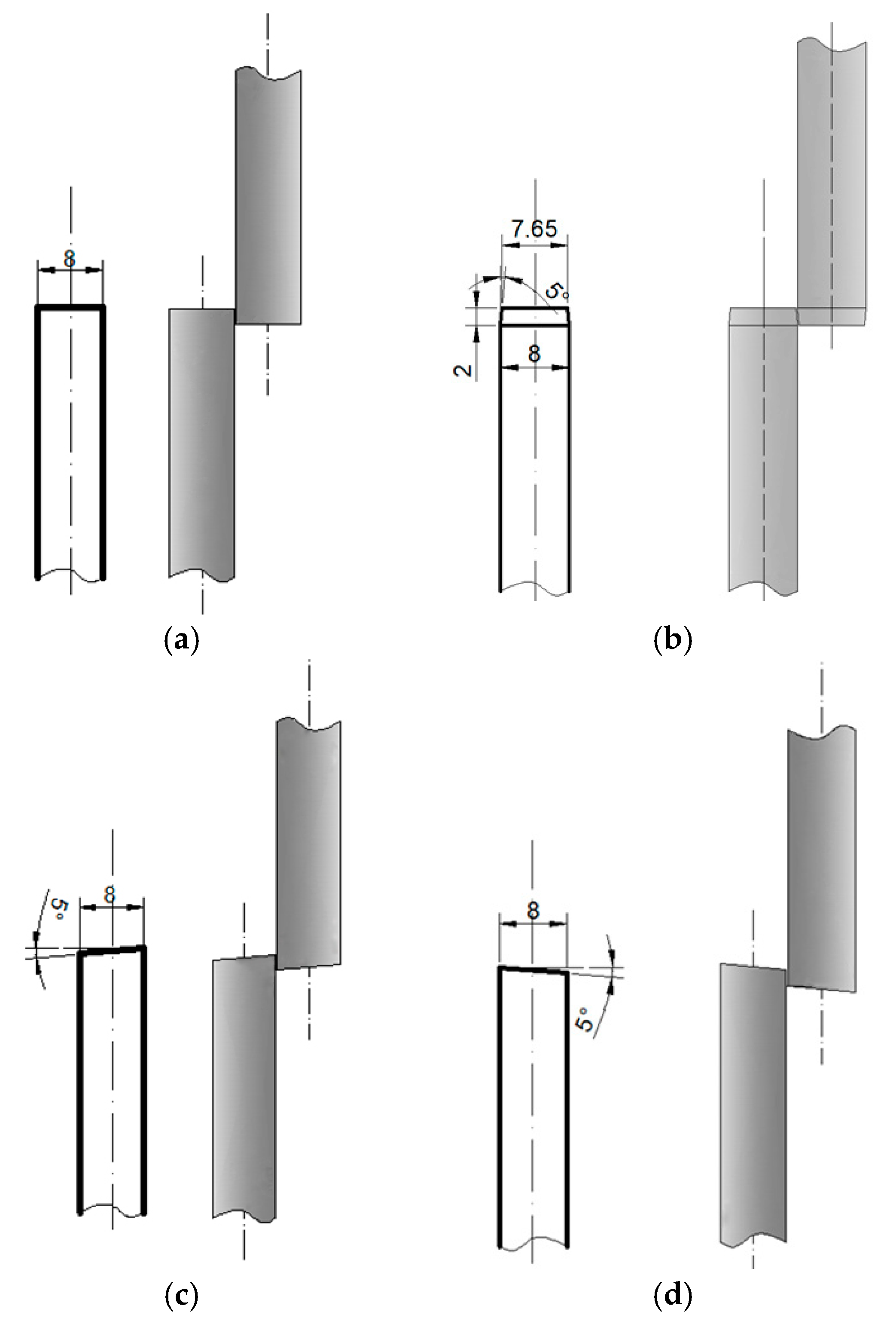
| Roller Type | Measur. No. 1 [mm] | Measur. No. 2 [mm] | Measur. No. 3 [mm] | Average | |||
|---|---|---|---|---|---|---|---|
| L1 | P1 | L2 | P2 | L3 | P3 | ||
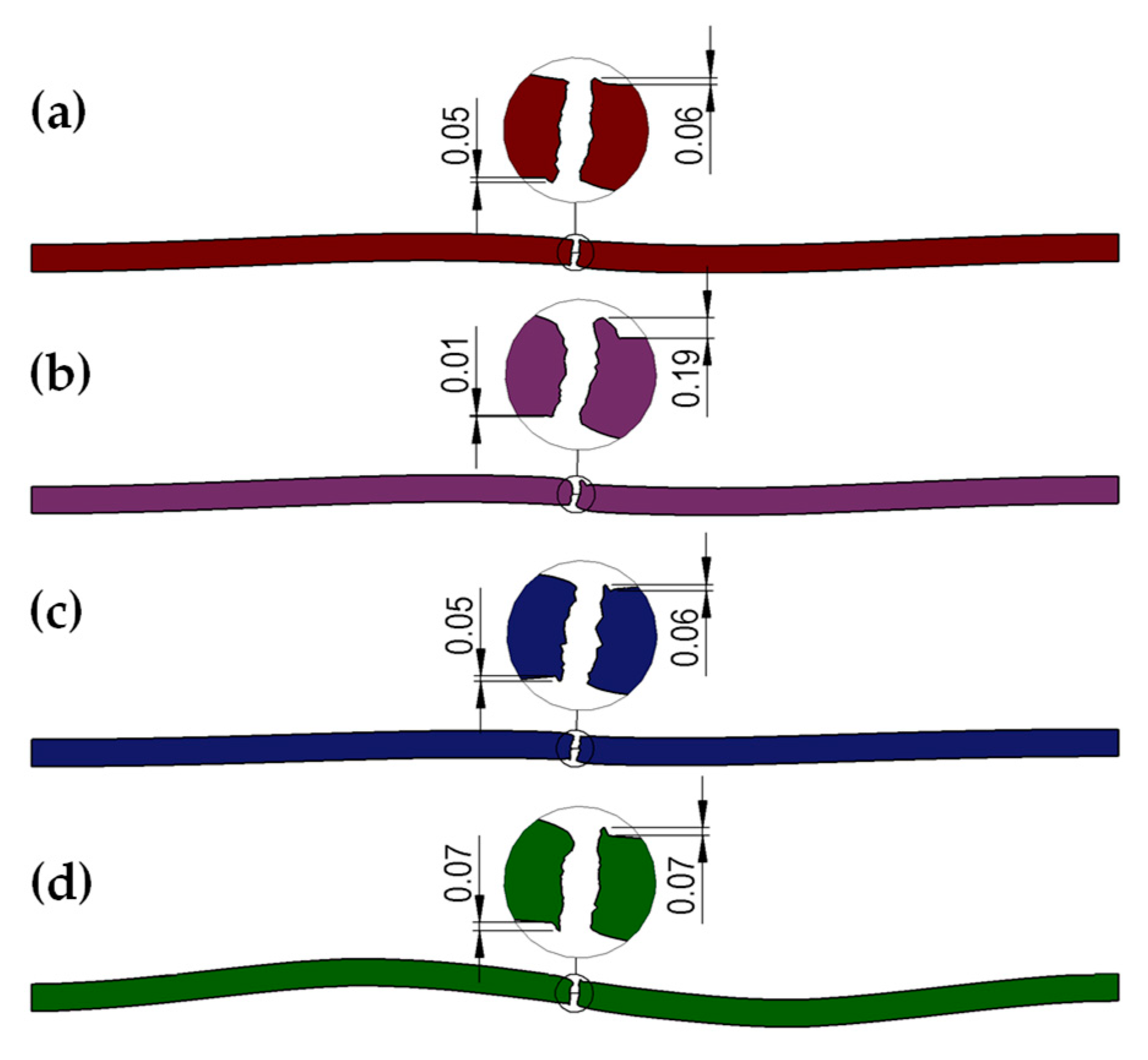
| 1.0 mm thick sheet metal | |||||||
| straight | 0.05 | 0.05 | 0.05 | 0.06 | 0.04 | 0.05 | 0.05 |
| trapezoidal | 0.02 | 0.15 | 0.01 | 0.19 | 0.02 | 0.18 | 0.17 |
| left-slanted | 0.05 | 0.07 | 0.05 | 0.06 | 0.05 | 0.06 | 0.06 |
| right-slanted | 0.08 | 0.07 | 0.07 | 0.08 | 0.07 | 0.06 | 0.07 |
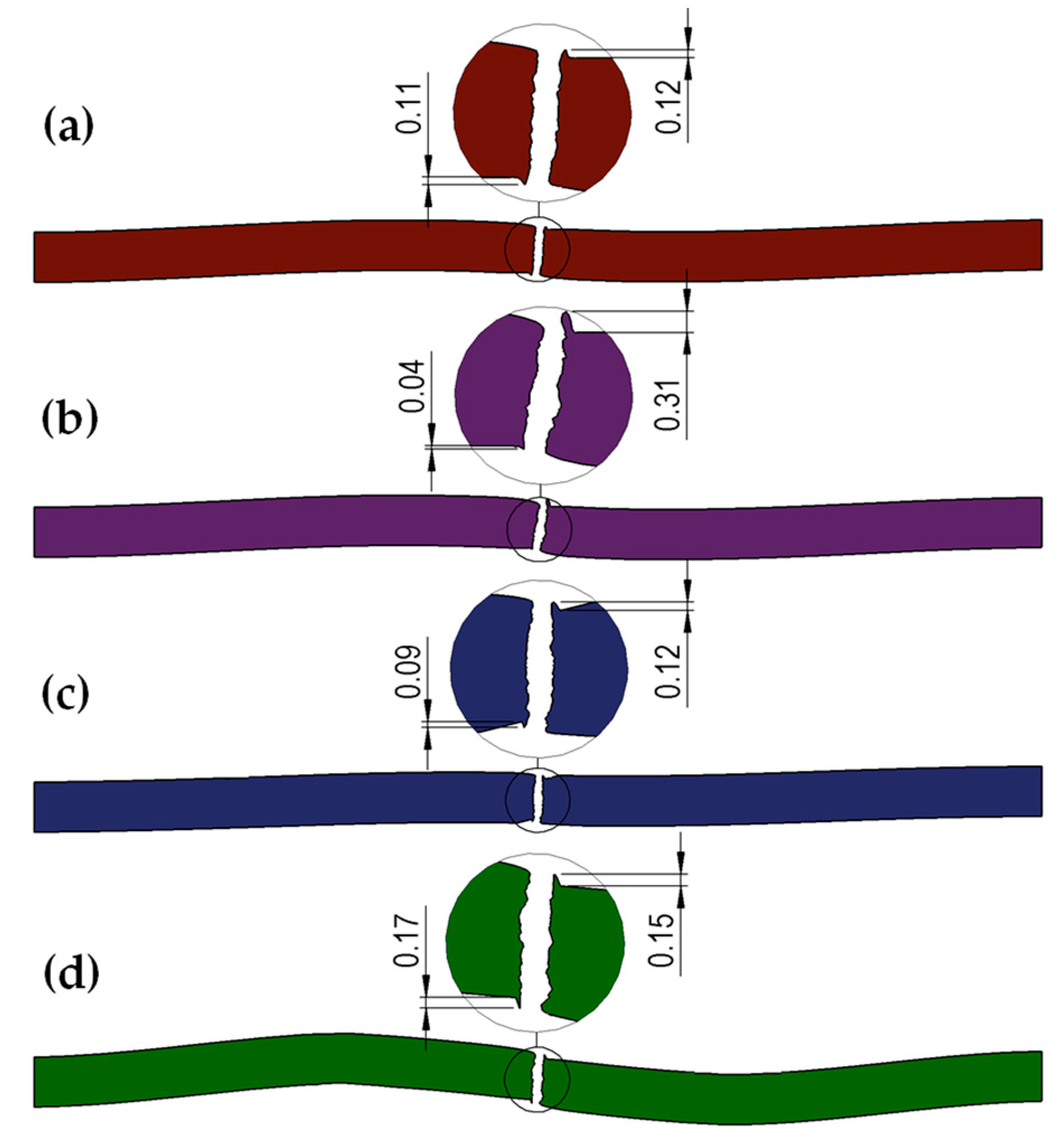
| 2.0 mm thick sheet metal | |||||||
| straight | 0.10 | 0.11 | 0.12 | 0.11 | 0.12 | 0.12 | 0.11 |
| trapezoidal | 0.04 | 0.35 | 0.04 | 0.31 | 0.07 | 0.35 | 0.33 |
| left-slanted | 0.11 | 0.12 | 0.09 | 0.12 | 0.12 | 0.11 | 0.11 |
| right-slanted | 0.14 | 0.15 | 0.17 | 0.15 | 0.15 | 0.16 | 0.15 |
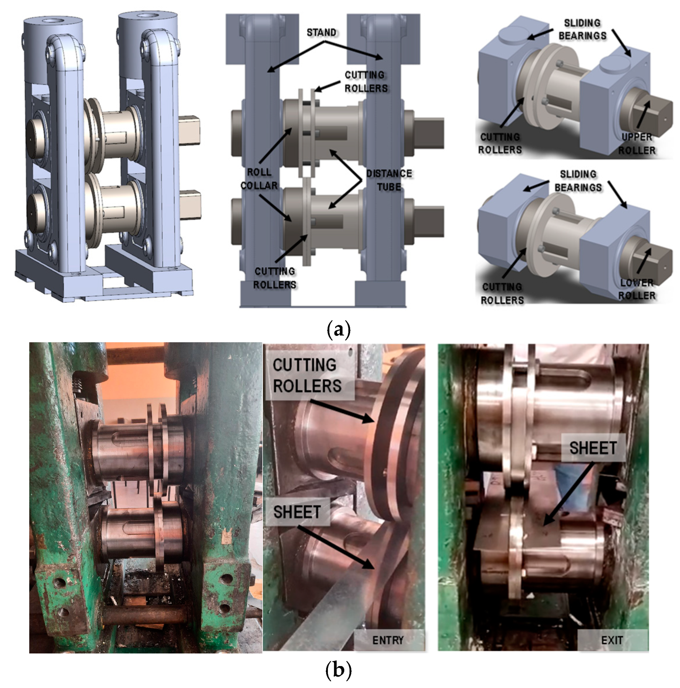
| Roller Type | Measurement Results, [mm] | av. Lab. Test [mm] | av. FEM [mm] | Difference Lab./FEM [%] | |||||
|---|---|---|---|---|---|---|---|---|---|
| L1 | P1 | L2 | P2 | L3 | P3 | ||||
| straight | 0.0487 | 0.0421 | 0.0456 | 0.0528 | 0.0485 | 0.0501 | 0.0476 | 0.053 | 9.5 |
| 0.0459 | 0.0471 | 0.0446 | 0.0503 | 0.0478 | 0.0511 | ||||
| 0.0456 | 0.0457 | 0.0513 | 0.0465 | 0.0477 | 0.0459 | ||||
| left-slanted | 0.0487 | 0.0492 | 0.0512 | 0.0437 | 0.0421 | 0.0474 | 0.0471 | 0.051 | 7.7 |
| 0.0507 | 0.0511 | 0.0476 | 0.0421 | 0.0438 | 0.0436 | ||||
| 0.0483 | 0.0502 | 0.0469 | 0.0485 | 0.0468 | 0.0454 | ||||
| Roller Type | Measurement Results, [mm] | av. Lab. Test [mm] | av. FEM [mm] | Difference Lab./FEM[%] | |||||
|---|---|---|---|---|---|---|---|---|---|
| L1 | P1 | L2 | P2 | L3 | P3 | ||||
| straight | 0.1083 | 0.1091 | 0.1138 | 0.1123 | 0.1098 | 0.1103 | 0.1106 | 0.121 | 8.6 |
| 0.1105 | 0.1074 | 0.1056 | 0.1082 | 0.1104 | 0.1083 | ||||
| 0.1142 | 0.1123 | 0.1094 | 0.1107 | 0.1172 | 0.1123 | ||||
| left-slanted | 0.1053 | 0.1014 | 0.1064 | 0.1026 | 0.1012 | 0.1035 | 0.1034 | 0.110 | 6.0 |
| 0.1026 | 0.1094 | 0.1023 | 0.1043 | 0.1022 | 0.1051 | ||||
| 0.1003 | 0.1014 | 0.1021 | 0.1009 | 0.1043 | 0.1052 | ||||
Disclaimer/Publisher’s Note: The statements, opinions and data contained in all publications are solely those of the individual author(s) and contributor(s) and not of MDPI and/or the editor(s). MDPI and/or the editor(s) disclaim responsibility for any injury to people or property resulting from any ideas, methods, instructions or products referred to in the content. |
© 2025 by the authors. Licensee MDPI, Basel, Switzerland. This article is an open access article distributed under the terms and conditions of the Creative Commons Attribution (CC BY) license (https://creativecommons.org/licenses/by/4.0/).
Share and Cite
Mróz, S.; Stefanik, A.; Szota, P.; Galusińska, S.; Zaława, D.; Adamiec, A.; Zaława, N. Investigation of the Effect of the Shape of Cutting Knives Limiting Burr in High-Strength Multiphase Steel Sheets. Materials 2025, 18, 282. https://doi.org/10.3390/ma18020282
Mróz S, Stefanik A, Szota P, Galusińska S, Zaława D, Adamiec A, Zaława N. Investigation of the Effect of the Shape of Cutting Knives Limiting Burr in High-Strength Multiphase Steel Sheets. Materials. 2025; 18(2):282. https://doi.org/10.3390/ma18020282
Chicago/Turabian StyleMróz, Sebastian, Andrzej Stefanik, Piotr Szota, Sabina Galusińska, Dariusz Zaława, Andrzej Adamiec, and Natalia Zaława. 2025. "Investigation of the Effect of the Shape of Cutting Knives Limiting Burr in High-Strength Multiphase Steel Sheets" Materials 18, no. 2: 282. https://doi.org/10.3390/ma18020282
APA StyleMróz, S., Stefanik, A., Szota, P., Galusińska, S., Zaława, D., Adamiec, A., & Zaława, N. (2025). Investigation of the Effect of the Shape of Cutting Knives Limiting Burr in High-Strength Multiphase Steel Sheets. Materials, 18(2), 282. https://doi.org/10.3390/ma18020282