
Effect and Mechanism Analysis of Process Parameters and Penetration State on Pore Defects of 1060/2A12 Dissimilar Aluminum Alloy Electron Beam Welding Joints

 ,
,
Abstract
1. Introduction
2. Experimental Procedure
3. Numerical Simulation Modeling
3.1. Modeling Assumptions and Governing Equations
3.1.1. Modeling Assumptions
- (1)
- Only the metal vapor reaction force , surface tension , and gravity G are considered as three main forces that affect the flow of liquid metal in the molten pool.
- (2)
- The EBW process includes the initial stage, quasi-steady-state stage, and end stage. The model only considers the flow state of the molten pool in the quasi-steady-state stage.
- (3)
- The initial working temperature is 293 K, and the air pressure in the vacuum area is set to 0 Pa.
- (4)
- The liquid metal inside the molten pool is a Newtonian fluid, which does not consider the flow of metal vapor and plasma inside the keyhole.
- (5)
- The specific heat capacity, dynamic viscosity, and thermal conductivity are all functions of temperature, and other metal properties are set as constants. The material is isotropic.
3.1.2. Governing Equations
3.2. Mesh Generation and Boundary Conditions
3.2.1. Mesh Generation
3.2.2. Boundary Conditions
- (1)
- Initial conditions
- (2)
- Momentum boundary conditions
- (3)
- Energy boundary conditions
3.3. Heat Source Model and Material Thermo-Physical Parameters
4. Results and Discussion
4.1. Influence of Process Parameters
4.1.1. Beam Current
4.1.2. Welding Speed
4.2. Analysis of Mechanism
4.2.1. Keyhole Behavior
4.2.2. The Influence Mechanism of Penetration State on Metallurgical Pores
4.2.3. The Influence Mechanism of Beam Current and Penetration State on Process Type Pores
4.2.4. The Influence Mechanism of Welding Speed on Pore Defects
5. Conclusions
- When the speed is constant, the porosity of the weld is related to the penetration state. Minimum joint porosity levels were achieved under critical penetration states (0.23% at 300 mm/min; 0.36% at 1200 mm/min), whereas full penetration exhibited an initial increase followed by a decrease in porosity with elevated thermal input. Under critical penetration conditions, the weld porosity first increases and subsequently decreases with rising welding speed, reaching a minimum of 0.23% at 300 mm/min.
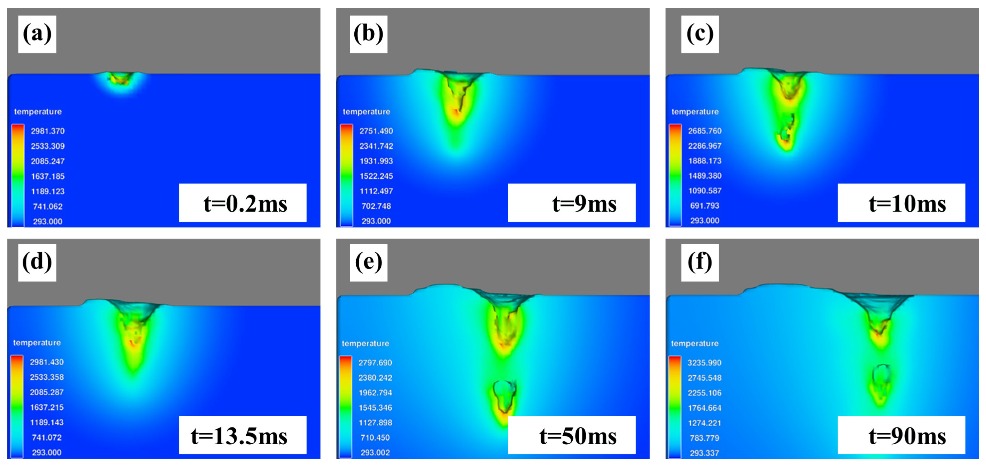
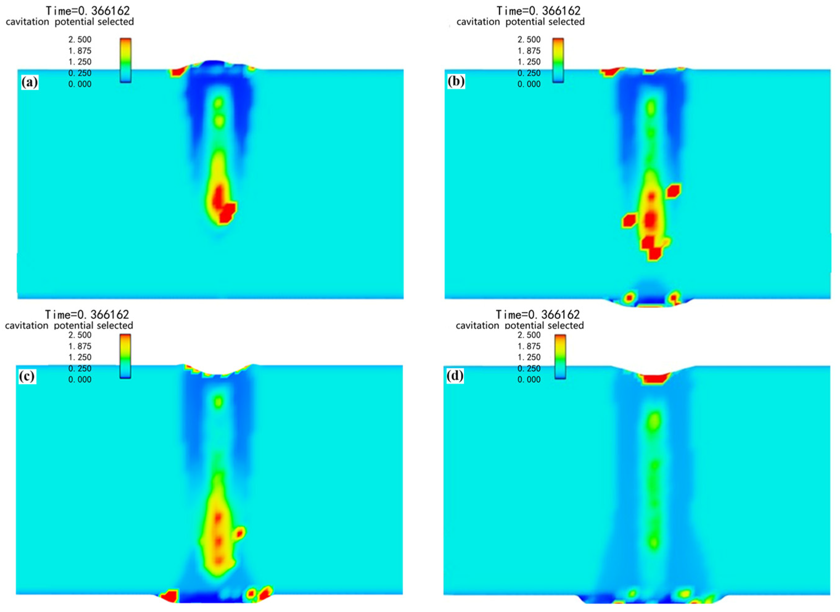
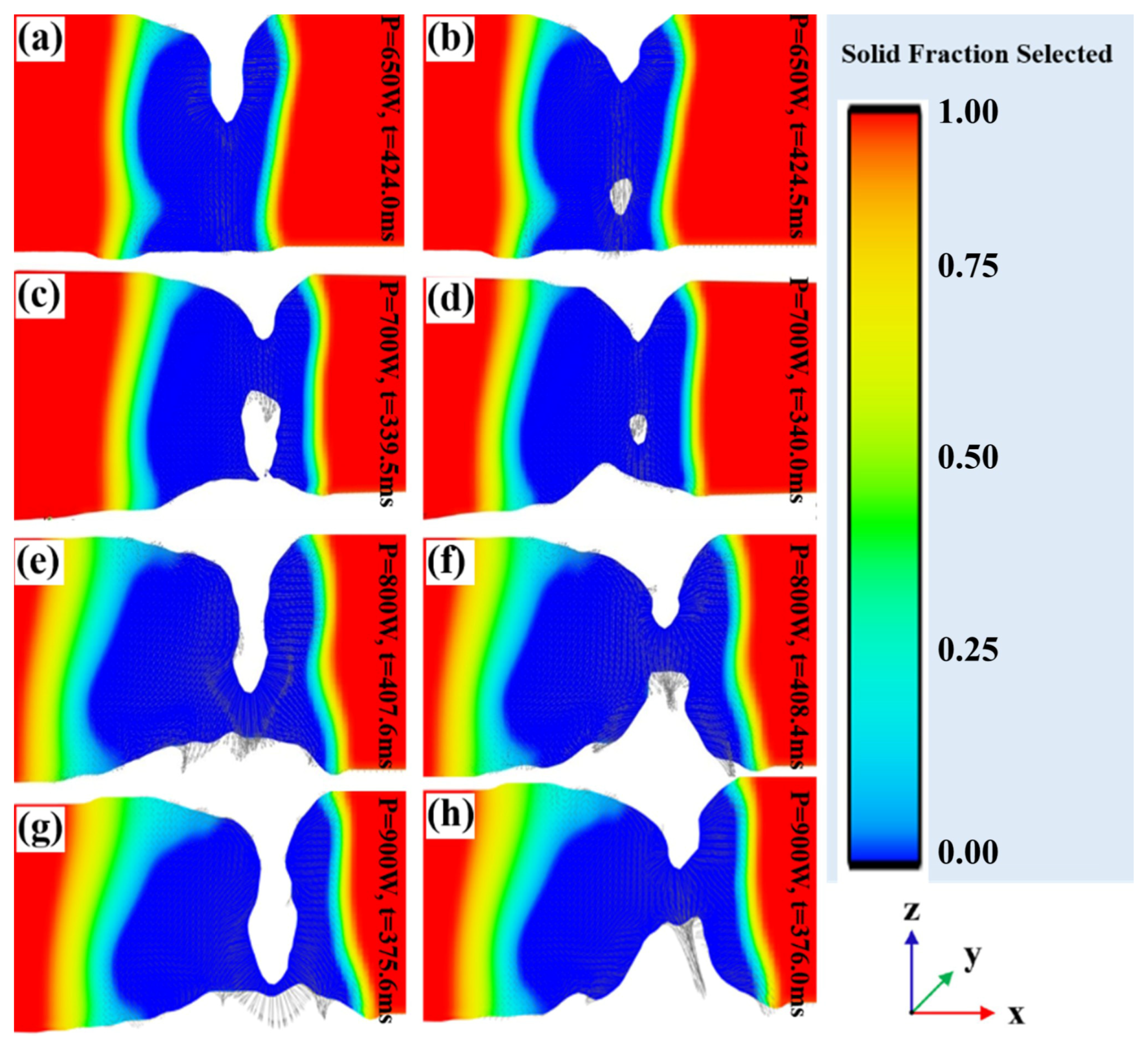
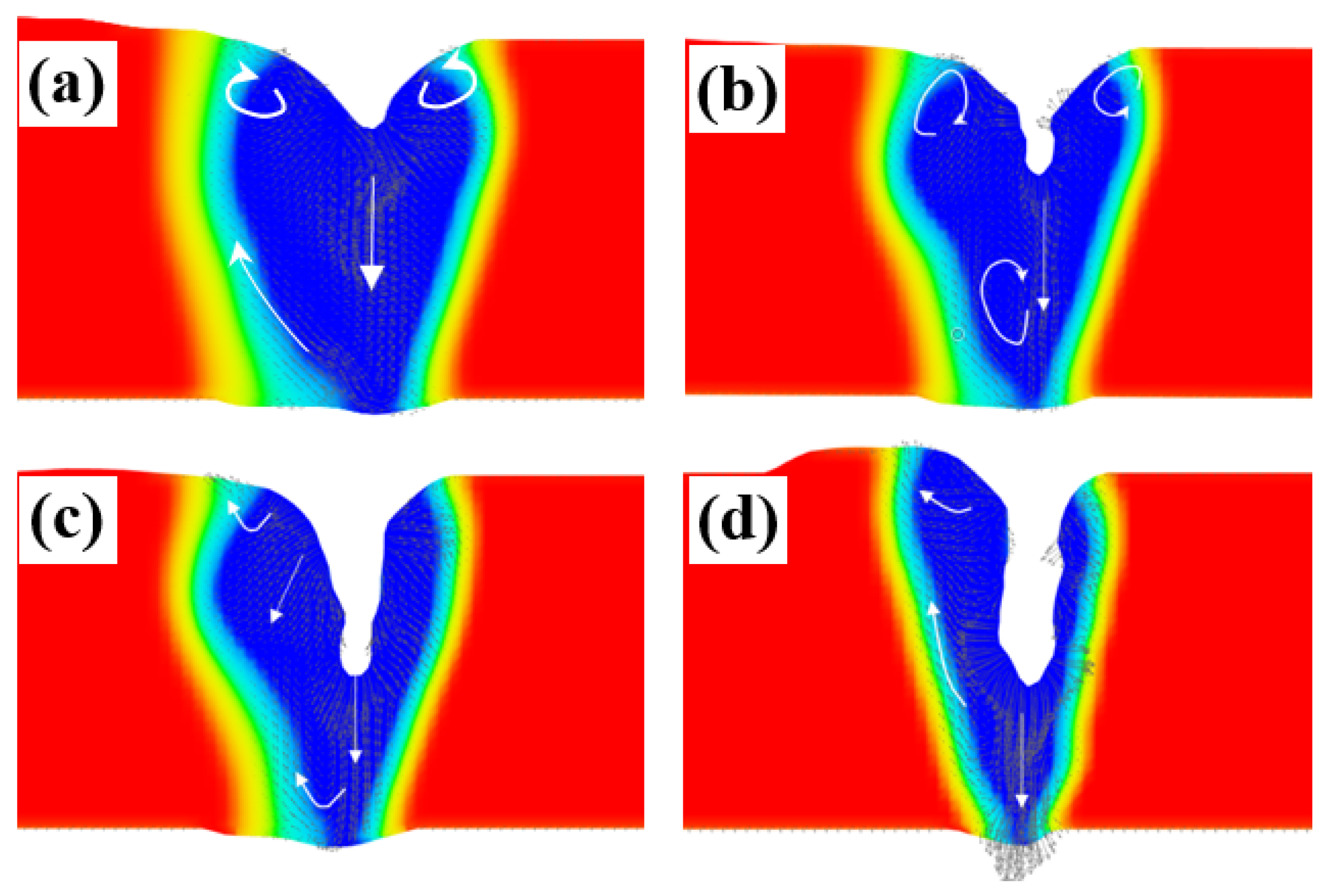
- During electron beam deep penetration welding, the stability of the keyhole depends on the balance between the reaction force of the metal vapor on the wall of the keyhole and the surface tension. Increasing the reaction force of the metal vapor is beneficial for improving the stability of the keyhole. In the unmelted joint, the bubbles can only escape from the upper surface after being generated, so the pore defects are more serious. When the molten pool exhibits micro-penetration, the metal vapor escapes from the lower surface, and the partial loss of the reaction force of the metal vapor reduces the keyhole’s stability. The behavior of the keyhole becomes stable when the beam current continues to increase. The problem of pore defects in the joints depends on two stages of bubble generation and floating. Using small and large specifications during welding is beneficial to stable the keyhole and molten pool flowing behavior, thereby reducing joint pore defects.
Author Contributions
Funding
Institutional Review Board Statement
Informed Consent Statement
Data Availability Statement
Conflicts of Interest
References
- Miller, W.S.; Zhuang, L.; Bottema, J.; Wittebrood, A.J.; De Smet, P.; Haszler, A.; Vieregge, A. Recent development in aluminium alloys for the automotive industry. Mater. Sci. Eng. A 2000, 280, 37–49. [Google Scholar] [CrossRef]
- Guo, N.; Fu, Y.; Wang, Y.; Meng, Q.; Zhu, Y. Microstructure and mechanical properties in friction stir welded 5A06 aluminum alloy thick plate. Mater. Des. 2017, 113, 273–283. [Google Scholar] [CrossRef]
- Ning, X.; Han, X.; Wang, X.; Hua, L.; Hu, X.; Ren, C. Grain size characterization of 5A06 aluminum alloy plates with different deformation amounts based on laser ultrasonic. Measurement 2024, 238, 113343. [Google Scholar] [CrossRef]
- Weglowski, M.S.; Błacha, S.; Phillips, A. Electron beam welding–techniques and trends–review. Vacuum 2016, 130, 72–92. [Google Scholar] [CrossRef]
- Riedlbauer, D.; Steinmann, P.; Mergheim, J. Thermomechanical finite element simulations of selective electron beam melting processes: Performance considerations. Comput. Mech. 2014, 54, 109–122. [Google Scholar] [CrossRef]
- Yu, Y.; Wang, C.; Hu, X.; Wang, J.; Yu, S. Porosity in fiber laser formation of 5A06 aluminum alloy. J. Mech. Sci. Technol. 2010, 24, 1077–1082. [Google Scholar] [CrossRef]
- Wang, J.; Peng, G.; Li, L.; Si, C.; Meng, S.; Gong, J. 30 kW-level laser welding characteristics of 5A06 aluminum alloy thick plate under subatmospheric pressure. Opt. Laser Technol. 2019, 119, 105668. [Google Scholar] [CrossRef]
- Manh, N.H.; Le, V.T.; Le Han, D.; Nguyen, V.-A. Successful joining of ultra-thin AA3003 aluminum alloy sheets by the novel GTAW process. Vacuum 2023, 207, 111558. [Google Scholar] [CrossRef]
- Huang, L.; Hua, X.; Wu, D.; Fang, L.; Cai, Y.; Ye, Y. Effect of magnesium content on keyhole-induced porosity formation and distribution in aluminum alloys laser welding. J. Manuf. Process. 2018, 33, 43–53. [Google Scholar] [CrossRef]
- Shen, H.; Yu, J.; Wang, L.; Vogel, F.; Li, C.; Nagaumi, H. A comparative filling materials study on microstructure and mechanical properties of welded joints of dissimilar Al–Mg–Si alloys using CMT-laser beam oscillation hybrid welding. J. Mater. Res. Technol. 2025, 34, 1029–1044. [Google Scholar] [CrossRef]
- Qu, M.; Guo, Q.; Escano, L.I.; Clark, S.J.; Fezzaa, K.; Chen, L. Mitigating keyhole pore formation by nanoparticles during laser powder bed fusion additive manufacturing. Addit. Manuf. Lett. 2022, 3, 100068. [Google Scholar] [CrossRef]
- Wang, L.; Zhang, Y.; Chia, H.Y.; Yan, W. Mechanism of keyhole pore formation in metal additive manufacturing. Comput. Mater. 2022, 1, 22. [Google Scholar] [CrossRef]
- Darwish, A.; Ericson, S.; Ghasemi, R.; Andersson, T.; Lönn, D.; Lassila, A.A.; Salomonsson, K. Investigating the ability of deep learning to predict Welding Depth and Pore Volume in Hairpin Welding. J. Laser Appl. 2024, 36, 042010. [Google Scholar] [CrossRef]
- Haboudou, A.; Peyre, P.; Vannes, A.; Peix, G. Reduction of porosity content generated during Nd:YAG laser welding of A356 and AA5083 aluminum alloys. Mater. Sci. Eng. A 2003, 363, 40–52. [Google Scholar] [CrossRef]
- Ola, O.T.; Doern, F.E. Keyhole-induced porosity in laser-arc hybrid welded aluminum. Int. J. Adv. Manuf. Technol. 2015, 80, 3–10. [Google Scholar] [CrossRef]
- Lee, J.; Jang, J.; Park, J.; Lee, S.H. Numerical and experimental analysis on the effect of ring beam-driven flow in coaxial dual-beam laser welding of aluminum alloy. Int. Commun. Heat Mass Transf. 2024, 157, 107800. [Google Scholar] [CrossRef]
- Mo, Z.; Wang, Y. Inhibit the porosity with electron beam scanning method in welding LD10 aluminum alloy. Rare Met. Mater. Eng. 2011, 40, 54–57. [Google Scholar]
- Dinda, S.K.; Warnett, J.M.; Williams, M.A.; Roy, G.G.; Srirangam, P. 3D imaging and quantification of porosity in electron beam welded dissimilar steel to Fe-Al alloy joints by X-ray tomography. Mater. Des. 2016, 96, 224–231. [Google Scholar] [CrossRef]
- Luo, Y.; Liu, J.; Ye, H. Bubble flow and the formation of cavity defect in weld pool of vacuum electron beam welding. Vacuum 2011, 86, 11–17. [Google Scholar] [CrossRef]
- Panwisawas, C.; Perumal, B.; Ward, R.M.; Turner, N.; Turner, R.P.; Brooks, J.W.; Basoalto, H.C. Keyhole formation and thermal fluid flow-induced porosity during laser fusion welding in titanium alloys: Experimental and modelling. Acta Mater. 2017, 126, 251–263. [Google Scholar] [CrossRef]
- Pang, S.; Chen, L.; Zhou, J.; Yin, Y.; Chen, T. A three-dimensional sharp interface model for self-consistent keyhole and weld pool dynamics in deep penetration laser welding. J. Phys. D Appl. Phys. 2011, 44, 025301. [Google Scholar] [CrossRef]
- Chongbunwatana, K. Simulation of vapour keyhole and weld pool dynamics during laser beam welding. Prod. Eng. 2014, 8, 499–511. [Google Scholar] [CrossRef]
- Li, P.; Li, F.-G.; Cao, J.; Ma, X.-K.; Li, J.-H. Constitutive equations of 1060 pure aluminum based on modified double multiple nonlinear regression model. Trans. Nonferrous Met. Soc. China 2016, 26, 1079–1095. [Google Scholar] [CrossRef]
- Xia, Y.; Shu, X.; Zhang, Q.; Pater, Z.; Li, Z.; Xu, H.; Ma, Z.; Xu, C. Modified Arrhenius constitutive model and simulation verification of 2A12-T4 aluminum alloy during hot compression. J. Mater. Res. Technol. 2023, 26, 1325–1340. [Google Scholar] [CrossRef]
- Yin, Q.; Yang, Z.; Li, H.; Du, H. Mechanism of keyhole evolution and welding quality of electron beam welded magnesium alloy with scanning path variation via modeling and numerical study. J. Magnes. Alloys 2024, in press. [Google Scholar] [CrossRef]
- Sahoo, P.; Debroy, T.; McNallan, M. Surface tension of binary metal—Surface active solute systems under conditions relevant to welding metallurgy. Metall. Trans. B 1988, 19, 483–491. [Google Scholar] [CrossRef]
- Wang, H. Research on Molten Pool Behavior and Metal Transfer During Electron Beam Welding Under Different Gravity Level. Ph.D. Thesis, Harbin Institute of Technology, Harbin, China, December 2017. [Google Scholar]
- Kovačócy, P.; Martinkovič, M.; Šimeková, B.; Hnilica, M.; Kovaříková, I.; Macháček, J.; Krbaťa, M. Influence of laser beam welding parameters on local mechanical properties of duplex stainless steel joints. Acta Polytech. CTU Proc. 2024, 50, 13–17. [Google Scholar] [CrossRef]
- Yang, Z.; Jin, K.; Fang, H.; He, J. Multi-scale simulation of solidification behavior and microstructure evolution during vacuum electron beam welding of Al-Cu alloy. Int. J. Heat Mass Transf. 2021, 172, 121156. [Google Scholar] [CrossRef]
- Krbata, M.; Ciger, R.; Kohutiar, M.; Sozańska, M.; Eckert, M.; Barenyi, I.; Kianicova, M.; Jus, M.; Beronská, N.; Mendala, B.; et al. Effect of Supercritical Bending on the Mechanical & Tribological Properties of Inconel 625 Welded Using the Cold Metal Transfer Method on a 16Mo3 Steel Pipe. Materials 2023, 16, 5014. [Google Scholar] [CrossRef]
- Krbata, M.; Krizan, D.; Eckert, M.; Kaar, S.; Dubec, A.; Ciger, R. Austenite Decomposition of a Lean Medium Mn Steel Suitable for Quenching and Partitioning Process: Comparison of CCT and DCCT Diagram and Their Microstructural Changes. Materials 2022, 15, 1753. [Google Scholar] [CrossRef]
- Lee, J.Y.; Ko, S.H.; Farson, D.F.; Yoo, C.D. Mechanism of keyhole formation and stability in stationary laser welding. J. Phys. D Appl. Phys. 2002, 35, 1570–1576. [Google Scholar] [CrossRef]
- Lin, R.; Wang, H.-P.; Lu, F.; Solomon, J.; Carlson, B.E. Numerical study of keyhole dynamics and keyhole-induced porosity formation in remote laser welding of Al alloys. Int. J. Heat Mass Transf. 2017, 108, 244–256. [Google Scholar] [CrossRef]
- Huang, L.; Hua, X.; Wu, D.; Li, F. Numerical study of keyhole instability and porosity formation mechanism in laser welding of aluminum alloy and steel. J. Mater. Process. Technol. 2018, 252, 421–431. [Google Scholar] [CrossRef]


| Component | Cu | Mg | Mn | Fe | Si | Zn | Ti | Al |
|---|---|---|---|---|---|---|---|---|
| 1060 | 0.05 | 0.03 | 0.03 | 0.35 | 0.25 | 0.05 | 0.03 | 99.60 |
| 2A12 | 3.80–4.90 | 1.20–1.80 | 0.30–0.90 | ≤0.50 | ≤0.50 | ≤0.30 | ≤0.15 | rest |
| Test | Welding Speed v (mm/min) | Beam Current Ib (mA) |
|---|---|---|
| 1 | 300 | 25 |
| 2 | 300 | 26 |
| 3 | 300 | 27 |
| 4 | 720 | 31 |
| 5 | 720 | 32 |
| 6 | 720 | 33 |
| 7 | 1200 | 34 |
| 8 | 1200 | 37 |
| 9 | 1200 | 41 |
| 10 | 1200 | 43 |
| 11 | 480 | 28 |
| 12 | 600 | 30 |
| 13 | 900 | 34 |
| 14 | 1500 | 41 |
| Speed/v (mm/min) | Distribution | Binarization |
|---|---|---|
| 300 | 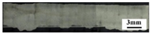 |  |
| 720 | 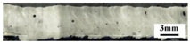 | 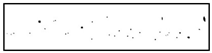 |
| 900 | 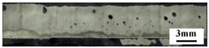 |  |
| 1200 | 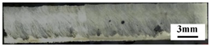 |  |
| 1500 | 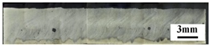 | 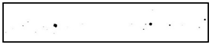 |
| Test | Welding Speed v (mm/min) | Power P (w) | Numbers of Bubbles |
|---|---|---|---|
| 1 | 1200 | 600 | 48 |
| 2 | 1200 | 650 | 25 |
| 3 | 1200 | 700 | 50 |
| 4 | 1200 | 800 | 18 |
| 5 | 1200 | 850 | 12 |
| 6 | 1200 | 900 | 9 |
Disclaimer/Publisher’s Note: The statements, opinions and data contained in all publications are solely those of the individual author(s) and contributor(s) and not of MDPI and/or the editor(s). MDPI and/or the editor(s) disclaim responsibility for any injury to people or property resulting from any ideas, methods, instructions or products referred to in the content. |
© 2025 by the authors. Licensee MDPI, Basel, Switzerland. This article is an open access article distributed under the terms and conditions of the Creative Commons Attribution (CC BY) license (https://creativecommons.org/licenses/by/4.0/).
Share and Cite
Ma, G.; Li, G.; Han, X.; Jiang, C.; Cheng, Z.; Diao, W.; Wang, H. Effect and Mechanism Analysis of Process Parameters and Penetration State on Pore Defects of 1060/2A12 Dissimilar Aluminum Alloy Electron Beam Welding Joints. Materials 2025, 18, 3477. https://doi.org/10.3390/ma18153477
Ma G, Li G, Han X, Jiang C, Cheng Z, Diao W, Wang H. Effect and Mechanism Analysis of Process Parameters and Penetration State on Pore Defects of 1060/2A12 Dissimilar Aluminum Alloy Electron Beam Welding Joints. Materials. 2025; 18(15):3477. https://doi.org/10.3390/ma18153477
Chicago/Turabian StyleMa, Guolong, Gangqing Li, Xiaohui Han, Chenghui Jiang, Zengci Cheng, Wangzhan Diao, and Houqin Wang. 2025. "Effect and Mechanism Analysis of Process Parameters and Penetration State on Pore Defects of 1060/2A12 Dissimilar Aluminum Alloy Electron Beam Welding Joints" Materials 18, no. 15: 3477. https://doi.org/10.3390/ma18153477
APA StyleMa, G., Li, G., Han, X., Jiang, C., Cheng, Z., Diao, W., & Wang, H. (2025). Effect and Mechanism Analysis of Process Parameters and Penetration State on Pore Defects of 1060/2A12 Dissimilar Aluminum Alloy Electron Beam Welding Joints. Materials, 18(15), 3477. https://doi.org/10.3390/ma18153477