
Multiphysics Modeling of Heat Transfer and Melt Pool Thermo-Fluid Dynamics in Laser-Based Powder Bed Fusion of Metals

 , , ,
, , , 
Abstract
1. Introduction
2. Model Description
2.1. Simulation Conditions
2.2. Mathematical Model
- (1)
- The fluid flow is Newtonian, laminar, and incompressible.
- (2)
- The vapor plume, comprising a metallic gas and an inert gas, is an ideal gas that is transparent to the incident laser beam.
- (3)
- The Boussinesq approximation is implemented in the numerical model to address thermal-induced density variations in the melt pool.
- (4)
- The enthalpy-porosity technique is adopted to simulate the metal powder melting and re-solidification process.
3. Results and Discussion
3.1. Melting and Solidification of Metal Powders and Model Validation
3.2. Effects of Laser Power and Porosity Formation Mechanism
3.3. Effects of Layer Thickness and Porosity Formation Mechanism
3.4. Process Parameter Optimization
4. Conclusions
- (1)
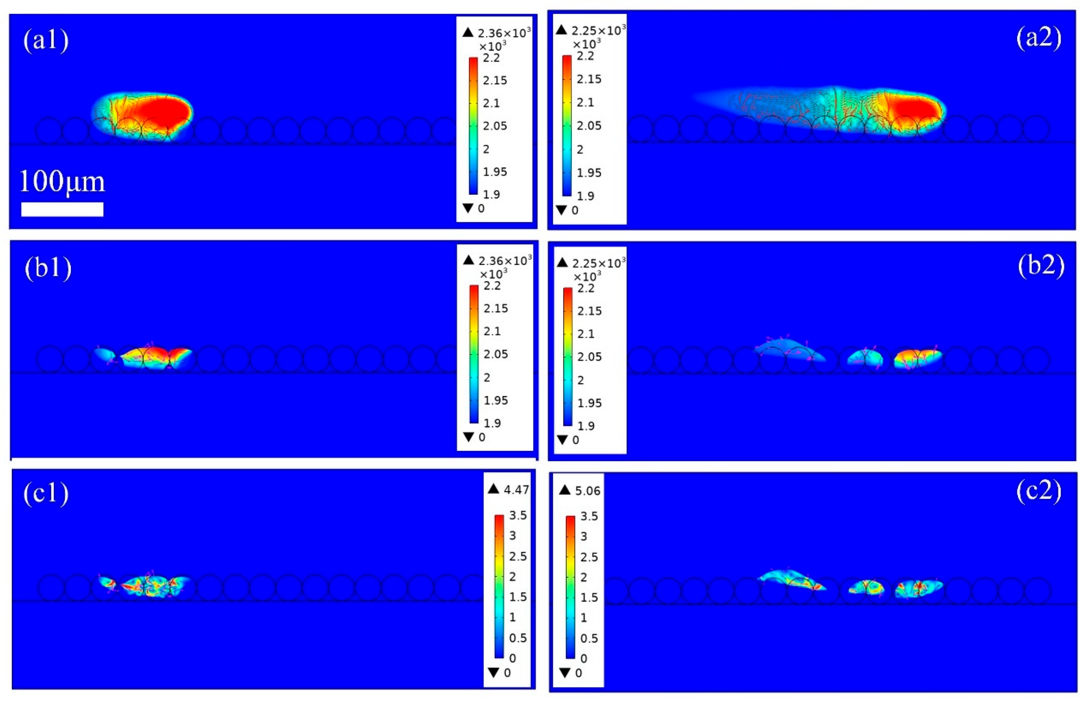
- With the lower volume energy density, the powder bed cannot be completely melted. Incomplete melting results in insufficient liquid spreading and limited liquid penetration, which causes higher porosity in the part due to insufficient liquid filling. Conversely, the higher volume energy density promotes gas dissolution, coalescence, and expulsion from the melt pool, with higher density in the part. Moreover, the porosity is usually exacerbated by rapid cooling rates, especially at the start and the end of the melt track.
- (2)
- The lower line energy density causes the metal powder to melt incompletely, especially with insufficient evaporation. The incomplete melting leads to a large dissipative force, which limits the further flow of the fluid and causes the melt pools to separate from each other, which also limits heat transfer and liquid infiltration, resulting in a lower bonding strength and a larger surface roughness of the finished part. However, the higher line energy density can improve the rate of melting and evaporation, and thus, improved surface quality and higher density are achieved.
Author Contributions
Funding
Institutional Review Board Statement
Informed Consent Statement
Data Availability Statement
Conflicts of Interest
References
- Gu, H.; Väistö, T.; Li, L. Numerical and experimental study on the molten pool dynamics and fusion zone formation in multi-pass narrow gap laser welding. Opt. Laser Technol. 2020, 126, 106081. [Google Scholar] [CrossRef]
- Zhang, G. Research on Design and Performance of High-Performance Porous Structure Based on 3D Printing Technology. J. Mater. Eng. Perform. 2024, 24, 7103–7112. [Google Scholar] [CrossRef]
- Zhang, K.; Chen, Y.; Marussi, S.; Fan, X.; Fitzpatrick, M.; Bhagavath, S.; Majkut, M.; Lukic, B.; Jakata, K.; Rack, A.; et al. Pore evolution mechanisms during directed energy deposition additive manufacturing. Nat. Commun. 2024, 15, 1715. [Google Scholar] [CrossRef]
- Bai, Y.; Wang, D.; Yang, Y.; Wang, H. Effect of heat treatment on the microstructure and mechanical properties of maraging steel by selective laser melting. Mater. Sci. Eng. A 2019, 760, 105–117. [Google Scholar] [CrossRef]
- Wu, Q. In-Situ Quality Intelligent Classification of Additively Manufactured Parts Using a Multi-Sensor Fusion Based Melt Pool Monitoring System. Addit. Manuf. Front. 2024, 3, 200153. [Google Scholar] [CrossRef]
- Jakumeit, J.; Zheng, G.; Laqua, R.; Clark, S.J.; Zielinski, J.; Schleifenbaum, J.H.; Lee, P.D. Modelling the complex evaporated gas flow and its impact on particle spattering during laser powder bed fusion. Addit. Manuf. 2021, 47, 102332. [Google Scholar] [CrossRef]
- Li, Z.; Li, H.; Yin, J.; Li, Y.; Nie, Z.; Li, X.; You, D.; Guan, K.; Duan, W.; Cao, L.; et al. A Review of Spatter in Laser Powder Bed Fusion Additive Manufacturing: In Situ Detection, Generation, Effects, and Countermeasures. Micromachines 2022, 13, 1366. [Google Scholar] [CrossRef] [PubMed]
- Wang, D.; Ye, G.; Dou, W.; Zhang, M.; Yang, Y.; Mai, S.; Liu, Y. Influence of spatter particles contamination on densification behavior and tensile properties of CoCrW manufactured by selective laser melting. Opt. Laser Technol. 2020, 121, 105678. [Google Scholar] [CrossRef]
- Li, E. Numerical studies of melt pool and gas bubble dynamics in laser powder bed fusion process. Addit. Manuf. 2022, 56, 102913. [Google Scholar] [CrossRef]
- Jin, P.; Tang, Q.; Li, K.; Feng, Q.; Ren, Z.; Song, J.; Nie, Y.; Ma, S. The relationship between the macro- and microstructure and the mechanical properties of selective-laser-melted Ti6Al4V samples under low energy inputs: Simulation and experiment. Opt. Laser Technol. 2022, 148, 107713. [Google Scholar] [CrossRef]
- Gunenthiram, V.; Peyre, P.; Schneider, M.; Dal, M.; Coste, F.; Koutiri, I.; Fabbro, R. Experimental analysis of spatter generation and melt-pool behavior during the powder bed laser beam melting process. J. Mater. Process. Technol. 2018, 251, 376–386. [Google Scholar] [CrossRef]
- Wu, C.; Zafar, M.Q.; Zhao, H.; Wang, Y.; Schöler, C.; Heinigk, C.; Nießen, M.; Schulz, W. Multi-physics modeling of side roughness generation mechanisms in powder bed fusion. Addit. Manuf. 2021, 47, 102274. [Google Scholar] [CrossRef]
- Tang, P.; Wang, S.; Duan, H.; Long, M.; Li, Y.; Fan, S.; Chen, D.J.J. The Formation of Humps and Ripples During Selective Laser Melting of 316l Stainless Steel. Addit. Manuf. Valid. Control. 2020, 72, 1128–1137. [Google Scholar] [CrossRef]
- Liu, Z.; Yang, Y.; Han, C.; Zhou, H.; Zhou, H.; Wang, M.; Liu, L.; Wang, H.; Bai, Y.; Wang, D. Effects of gas flow parameters on droplet spatter features and dynamics during large-scale laser powder bed fusion. Mater. Des. 2023, 225, 111534. [Google Scholar] [CrossRef]
- Zhu, K.; Wang, Q.; Lin, X.; Fu, Y. Elective laser melting process state monitoring method based on motion feature of melt pool. Comput. Integr. Manuf. Syst. 2021, 27, 3404–3415. [Google Scholar]
- Hojjatzadeh, S.M.H.; Guo, Q.; Parab, N.D.; Qu, M.; Escano, L.I.; Fezzaa, K.; Everhart, W.; Sun, T.; Chen, L. In-Situ Characterization of Pore Formation Dynamics in Pulsed Wave Laser Powder Bed Fusion. Materials 2021, 14, 2936. [Google Scholar] [CrossRef]
- King, W.E.; Barth, H.D.; Castillo, V.M.; Gallegos, G.F.; Gibbs, J.W.; Hahn, D.E.; Kamath, C.; Rubenchik, A.M. Observation of keyhole-mode laser melting in laser powder-bed fusion additive manufacturing. J. Mater. Process. Technol. 2014, 214, 2915–2925. [Google Scholar] [CrossRef]
- Zhao, C.; Fezzaa, K.; Cunningham, R.W.; Wen, H.; De Carlo, F.; Chen, L.; Rollett, A.D.; Sun, T. Real-time monitoring of laser powder bed fusion process using high-speed X-ray imaging and diffraction. Sci. Rep. 2017, 7, 3602. [Google Scholar] [CrossRef]
- Hooper, P.A. Melt pool temperature and cooling rates in laser powder bed fusion. Addit. Manuf. 2018, 22, 548–559. [Google Scholar] [CrossRef]
- Cla, L.; Marussi, S.; Atwood, R.C.; Towrie, M.; Withers, P.J.; Lee, P.D. In situ X-ray imaging of defect and molten pool dynamics in laser additive manufacturing. Nat. Commun. 2018, 9, 1355. [Google Scholar]
- Hojjatzadeh, S.M.H.; Parab, N.D.; Yan, W.; Guo, Q.; Xiong, L.; Zhao, C.; Qu, M.; Escano, L.I.; Xiao, X.; Fezzaa, K.; et al. Pore elimination mechanisms during 3D printing of metals. Nat. Commun. 2019, 10, 3088. [Google Scholar] [CrossRef] [PubMed]
- Guo, Q.; Zhao, C.; Qu, M.; Xiong, L.; Hojjatzadeh, S.M.H.; Escano, L.I.; Parab, N.D.; Fezzaa, K.; Sun, T.; Chen, L. In-situ full-field mapping of melt flow dynamics in laser metal additive manufacturing. Addit. Manuf. 2020, 31, 100939. [Google Scholar] [CrossRef]
- Cunningham, R.; Zhao, C.; Parab, N.; Kantzos, C.; Pauza, J.; Fezzaa, K.; Sun, T.; Rollett, A.D.J.S. Keyhole threshold and morphology in laser melting revealed by ultrahigh-speed x-ray imaging. Science 2019, 363, 849–852. [Google Scholar] [CrossRef] [PubMed]
- Zhu, Q.; Liu, Z.; Yan, J.J.C.M. Machine learning for metal additive manufacturing: Predicting temperature and melt pool fluid dynamics using physics-informed neural networks. Comput. Mech. 2021, 67, 619–635. [Google Scholar] [CrossRef]
- Wu, C.; Zhao, H.; Li, H.; Lin, F. Track irregularity behaviours in electron beam selective melting. Sci. Technol. Weld. Join. 2022, 28, 27–37. [Google Scholar] [CrossRef]
- Gu, H.; Väistö, T.; Wei, C.; Li, L.; Ren, X.; Qian, L. A coupled ray-tracing based CFD and cellular automaton model for predicting molten pool formation and microstructure evolution in narrow gap laser welding. Int. J. Heat Mass Transf. 2023, 209, 124115. [Google Scholar] [CrossRef]
- Zhang, W.; Roy, G.G.; Elmer, J.W.; DebRoy, T. Modeling of heat transfer and fluid flow during gas tungsten arc spot welding of low carbon steel. J. Appl. Phys. 2003, 93, 3022–3033. [Google Scholar] [CrossRef]
- Körner, C.; Attar, E.; Heinl, P. Mesoscopic simulation of selective beam melting processes. J. Mater. Process. Technol. 2011, 211, 978–987. [Google Scholar] [CrossRef]
- Bayat, M.; Dong, W.; Thorborg, J.; To, A.C.; Hattel, J.H. A review of multi-scale and multi-physics simulations of metal additive manufacturing processes with focus on modeling strategies. Addit. Manuf. 2021, 47, 102278. [Google Scholar] [CrossRef]
- Cao, L.; Yuan, X. Study on the Numerical Simulation of the SLM Molten Pool Dynamic Behavior of a Nickel-Based Superalloy on the Workpiece Scale. Materials 2019, 12, 2272. [Google Scholar]
- Cao, L. Mesoscopic-scale numerical investigation including the influence of scanning strategy on selective laser melting process. Comput. Mater. Sci. 2021, 189, 110263. [Google Scholar] [CrossRef]
- Khairallah, S.A.; Anderson, A.T.; Rubenchik, A.; King, W.E. Laser powder-bed fusion additive manufacturing: Physics of complex melt flow and formation mechanisms of pores, spatter, and denudation zones. Acta Mater. 2016, 108, 36–45. [Google Scholar] [CrossRef]
- Long, Y.; An, X.; Wang, J.; Li, M.; Wu, Q.; Jiang, C.; Liu, J.; Ren, D.; Ji, H.; Li, S.; et al. Surface roughness and pore evolutions in multi-layer laser powder bed fusion of extra-low interstitial Ti-5Al-2.5Sn powder: A numerical study. Addit. Manuf. 2024, 95, 104530. [Google Scholar] [CrossRef]
- Zhang, Y.; Wu, S.; Guo, Z.; Peng, G.; Wang, L.; Yan, W. Defects caused by powder spattering and entrainment in laser powder bed fusion process: High-fidelity modeling of gas, melt pool and powder dynamics. Acta Mater. 2025, 288, 120816. [Google Scholar] [CrossRef]
- Yu, T.; Zhao, J. Quantitative simulation of selective laser melting of metals enabled by new high-fidelity multiphase, multiphysics computational tool. Comput. Methods Appl. Mech. Eng. 2022, 399, 115422. [Google Scholar] [CrossRef]
- Bayat, M.; Thanki, A.; Mohanty, S.; Witvrouw, A.; Yang, S.; Thorborg, J.; Tiedje, N.S.; Hattel, J.H. Keyhole-induced porosities in Laser-based Powder Bed Fusion (L-PBF) of Ti6Al4V: High-fidelity modelling and experimental validation. Addit. Manuf. 2019, 30, 100835. [Google Scholar] [CrossRef]
- Yu-Che, W.; San, C.-H.; Chang, C.-H.; Lin, H.-J.; Marwan, R.; Baba, S.; Hwang, W.-S. Numerical modeling of melt-pool behavior in selective laser melting with random powder distribution and experimental validation. J. Mater. Process. Technol. 2018, 254, 72–78. [Google Scholar] [CrossRef]
- Yan, W.; Qian, Y.; Ge, W.; Lin, S.; Liu, W.K.; Lin, F.; Wagner, G.J. Meso-scale modeling of multiple-layer fabrication process in Selective Electron Beam Melting: Inter-layer/track voids formation. Mater. Des. 2018, 141, 210–219. [Google Scholar] [CrossRef]
- Wei, H.L.; Cao, Y.; Liao, W.H.; Liu, T.T. Mechanisms on inter-track void formation and phase transformation during laser Powder Bed Fusion of Ti-6Al-4V. Addit. Manuf. 2020, 34, 101221. [Google Scholar] [CrossRef]
- Zhang, T.; Li, H.; Zhang, C.; Zhang, A. Effects of Beam Mode on Hole Properties in Laser Processing. Coatings 2024, 14, 594. [Google Scholar] [CrossRef]
- Chouhan, A.; Aggarwal, A.; Kumar, A. Role of melt flow dynamics on track surface morphology in the L-PBF additive manufacturing process. Int. J. Heat Mass Transf. 2021, 178, 121602. [Google Scholar] [CrossRef]


| Parameter (Symbol/Unit) | Value |
|---|---|
| Laser power (P/W) | 120, 135, 175, 200 |
| Laser beam radiμs (r0/μm) | 35 |
| Laser scan speed (v/m/s) | 1.8, 2 |
| Powder thickens (H/μm) | 30, 34, 60 |
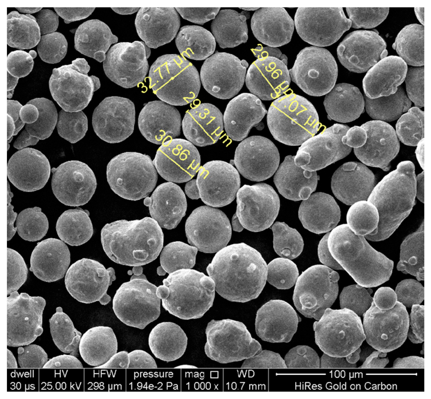
| Particle diameter (D/μm) | 30, 15 |
| Nomenclature | Value | Nomenclature | Value |
|---|---|---|---|
| Liquid Density () | 4000 kg/m3 | Melting Temperature (Tm) | 1923 K |
| Gas Density () | 39.95 × 10⁻³ kg/mol | Boiling Temperature (Tv) | 3315 K |
| Viscosity () | 5 × 10⁻³ Pa s | Boltzmann Constant (kb) | 1.38 × 10⁻²³ J/K |
| Specific Heat () | 610 J/(kg/K) | Level-Set Parameter () | 10 m/s |
| Latent Heat of Fusion (Lm) | 2.86 × 10⁵ J/kg | Level-Set Parameter () | 1.5 × 10⁻⁵ m |
| Latent Heat of Evaporation (Lv) | 2.84 × 10⁷ J/kg | Coefficient of Thermal Expansion (βl) | 8 × 10⁻⁴ K−1 |
| Thermal Conductivity (k) | 30 W/(m/K) | Surface Tension | 1.6–0.00015T N/m |
| Drag Coefficient (K0) | 6 × 10⁴ kg/(m^3*s) | Surface Tension Gradient ) | −0.00015 N/(m/K) |
| Denominator () | 0.001 | Heat Transfer Coefficient (hc) | 20 W/(m2 K4) |
Disclaimer/Publisher’s Note: The statements, opinions and data contained in all publications are solely those of the individual author(s) and contributor(s) and not of MDPI and/or the editor(s). MDPI and/or the editor(s) disclaim responsibility for any injury to people or property resulting from any ideas, methods, instructions or products referred to in the content. |
© 2025 by the authors. Licensee MDPI, Basel, Switzerland. This article is an open access article distributed under the terms and conditions of the Creative Commons Attribution (CC BY) license (https://creativecommons.org/licenses/by/4.0/).
Share and Cite
Zhang, T.; Lin, X.; Qin, Y.; Zhu, D.; Wang, J.; Zhang, C.; Bai, Y. Multiphysics Modeling of Heat Transfer and Melt Pool Thermo-Fluid Dynamics in Laser-Based Powder Bed Fusion of Metals. Materials 2025, 18, 3183. https://doi.org/10.3390/ma18133183
Zhang T, Lin X, Qin Y, Zhu D, Wang J, Zhang C, Bai Y. Multiphysics Modeling of Heat Transfer and Melt Pool Thermo-Fluid Dynamics in Laser-Based Powder Bed Fusion of Metals. Materials. 2025; 18(13):3183. https://doi.org/10.3390/ma18133183
Chicago/Turabian StyleZhang, Tingzhong, Xijian Lin, Yanwen Qin, Dehua Zhu, Jing Wang, Chengguang Zhang, and Yuchao Bai. 2025. "Multiphysics Modeling of Heat Transfer and Melt Pool Thermo-Fluid Dynamics in Laser-Based Powder Bed Fusion of Metals" Materials 18, no. 13: 3183. https://doi.org/10.3390/ma18133183
APA StyleZhang, T., Lin, X., Qin, Y., Zhu, D., Wang, J., Zhang, C., & Bai, Y. (2025). Multiphysics Modeling of Heat Transfer and Melt Pool Thermo-Fluid Dynamics in Laser-Based Powder Bed Fusion of Metals. Materials, 18(13), 3183. https://doi.org/10.3390/ma18133183