
A Review of Damage Tolerance and Mechanical Behavior of Interlayer Hybrid Fiber Composites for Wind Turbine Blades


Abstract
1. Introduction
1.1. Background: Impact Loads on Wind Turbine Blades and Design Approaches
1.2. Fiber Hybridization
1.3. Scope, Novelty, and Structure of the Review Paper
1.4. Study Limitations
2. DTD of Composite Laminates for WTBs
2.1. Key Elements in DTD of Composite Laminates Based on Aircraft Structures
- Critical Load: The DTD framework begins with the identification of the most critical load expected to affect a structure during its service life, specifically focusing on loads that could lead to unacceptable structural damages. This involves evaluating all potential load scenarios and determining which poses the greatest risk to the structure’s integrity.
- Damage Inspection and Relevant Energy Absorption Mechanisms (EAM): This aspect entails inspecting and identifying the EAMs associated with the critical load. It involves a detailed quantification of the size, location, and distribution of damages, which are crucial for understanding the effect of the critical load on the structure.
- Stress Analysis: A comprehensive stress analysis is conducted in the vicinity of the damage. This analysis aims to ascertain the level of criticality of the damage, determining whether it is likely to undergo stable or unstable growth, which is vital for planning appropriate responses.
- Post-Damage Loading: This element is concerned with characterizing the progression of damage in relation to cyclic loads, such as gravity and aerodynamic loads. It examines the relationship between damage growth and the number of cycles, considering different cyclic load directions, for example, tension-compression cyclic load.
- Residual Characteristics: Assessing the post-damage structural capacity is key in this aspect. It involves measuring the quasi-static properties (like compressive strength and modulus) and determining the fatigue life, providing insights into the structure’s performance after sustaining damage.
- Design and Optimization: The final element involves employing various strategies to enhance the damage tolerance of the structure. This could include modifying the stacking sequence or other design parameters to improve the overall resilience of the structure to the identified critical loads.
2.2. Critical Load
2.3. Energy Absorption Mechanisms and Damage Size
2.4. Residual Characteristics
2.4.1. Relationship Between Residual Strength and Damage Size
- Ultimate strength—This is the highest residual strength a pristine composite can exhibit, signifying its capability to bear the maximum load.
- Ultimate load—This is the residual strength corresponding to the ‘design load’ as defined in [86], which the composite should maintain despite these damages being undetected, such as porosity or minor delaminations.
- Limit service load—This is the minimum residual strength that a damaged composite should uphold until repair to guarantee operational safety and structural integrity. This also corresponds to the ‘characteristic load’ in [86].
- Critical size—The point at which the residual strength falls below the limit service load due to damage, necessitating immediate repair.
2.4.2. Key Residual Mechanical Properties in WTBs Affected by Delamination
- Tensile strength: Delamination has a minor effect on the in-plane tensile strength of composites as the fibers close to the delamination zone can retain their load-carrying capacity under tension [71,73,93,94,95,96]. For instance, the tensile strength of the spar cap on the pressure side of a WTB shows only an 11% decrease in the presence of delamination [97]. Therefore, this mechanical property due to delamination in WTBs is not considered in this review paper.
- Flexural strength: Delaminations induced by shear stress at the laminate mid-section can affect the flexural strength of composite laminates by changing shear stress distribution [98]. Also, during the flexural load, delaminations on the compressive side of the laminate, i.e., the suction side of the spar cap, can reduce the flexural strength because of induced local buckling [95,99].
- Compressive strength: Typically, delamination influences the compressive strength of the composite laminates. The reduction in the compressive strength in the presence of delamination is often associated with progressive local buckling [100]. In WTBs, large and deep delaminations are prone to rapid growth, reducing the compressive strength of the blade due to higher elastic energy that drives the delamination growth [101].
- Shear strength: The in-plane shear strength is highly influenced by delamination [102]. In addition, delamination reduces the buckling load under in-plane shear. Studies have shown that long, slender [103], and circular delaminations [104] greatly affect the shear strength. A critical failure mode of large WTBs under shear loads is the cross-sectional shear distortion result from the change in the angle of the edgewise load [105]. This mechanism in WTBs can contribute to delamination growth and premature shear buckling.
- Buckling strength: Delamination greatly affects the buckling strength of composite laminates under compressive loads [71,82]. Delamination results in the formation of sublaminates by separating adjacent layers [76]. Also, delamination size and depth affect the buckling mode. For a WTB, the two critical buckling modes are (I) global–local, induced by a large delamination close to the middle of the laminate [76,106], and (II) local buckling, induced by a large delamination close to the free surface under compressive load [72,107]. The formation of both buckling modes in a WTB has serious consequences on delamination growth (buckling-driven delamination) and the load-carrying capacity of WTBs.
- Fatigue strength: Delamination growth under fatigue loads is very complex, and many aspects of this phenomenon are not well-captured [85]. The literature reports an 18–23% decrease in the failure stress level of composite laminates in case of minor delamination [92,108]. Furthermore, delamination growth depends on the applied load direction, e.g., under tension fatigue loads, delamination can propagate from the near-surface regions of the composite laminate due to the induced intralaminar damage [109]. Under compression fatigue loads, due to buckling, delamination extends normal to the load direction [110]. The literature further reports a notable reduction in stiffness compared to the strength under fatigue loads in the presence of delamination [92]. This highlights the importance of quantifying the residual stiffness in fatigue loads, as the loss of blade stiffness leads to blade collision with the tower.
2.5. Summary of Discussed Key Elements in DTD of Composite Laminates for WTBs

| Key Element ⋄ | Element | Variable | Evaluation |
|---|---|---|---|
| 1 | Critical load | Transverse impact load | Drop-weight impact test |
| 2 | Major energy absorption mechanisms | Matrix cracking Delamination Fiber breakage | NDT, e.g., acoustic emission |
| Damage size | Delamination size | NDT, e.g., C-Scan | |
| 5 | Residual characteristics | Flexural * Compression Shear * Buckling | Coupon testing |
| Fatigue | Coupon testing †,§: 1. Tension-compression (R = −1) 2. Tension-tension (R = 0.1) and compression-compression (R = 10) | ||
| Stiffness | 1. Deformation analysis § 2. Full-scale static test § |
3. Damage Tolerance of Different Hybrid Lay-Up Configurations: A Qualitative Analysis
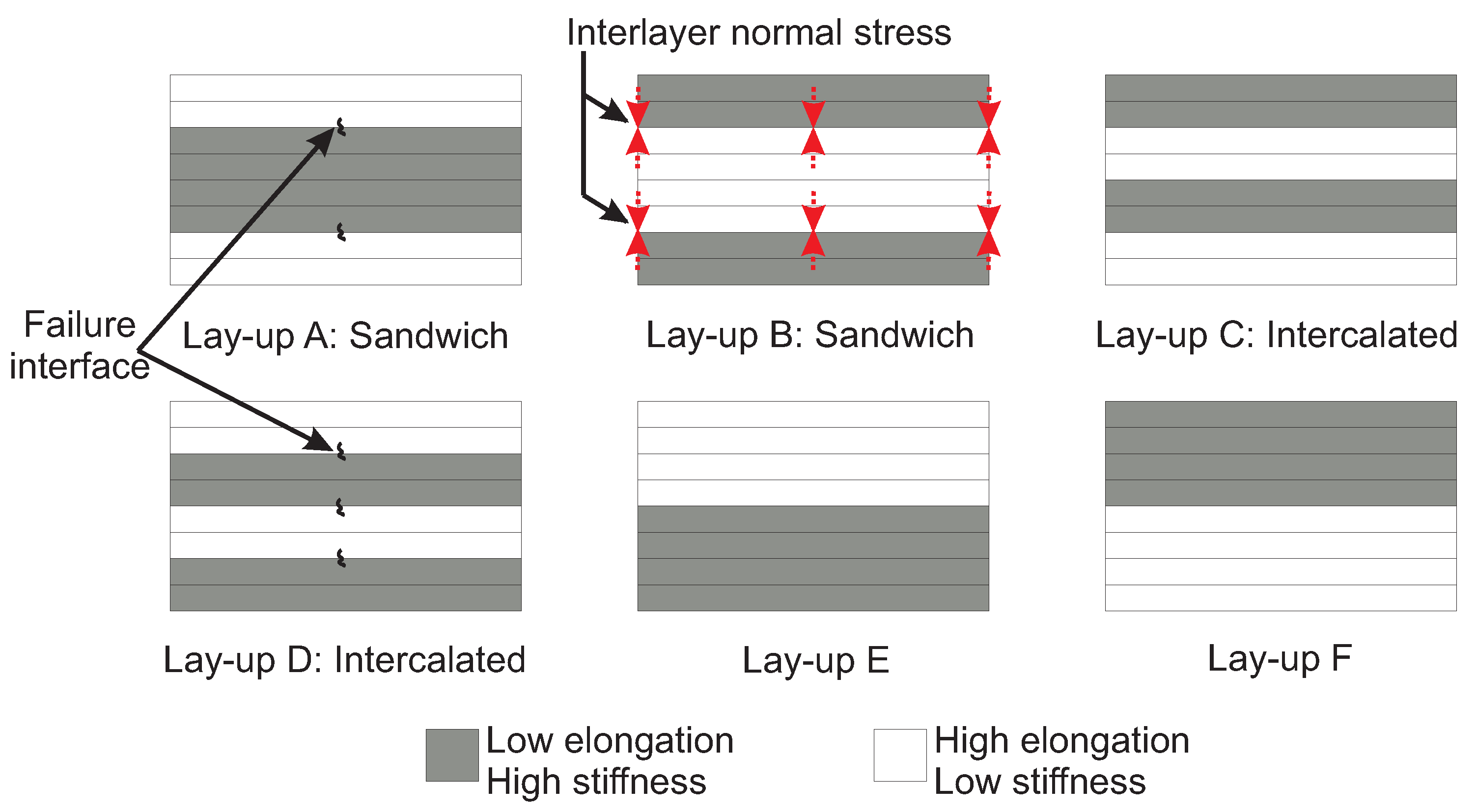
- Different configurations of interlayer hybrid lay-ups: While various interlayer hybrid lay-ups exist in the literature, the hybrid lay-ups can be broadly classified into six lay-up configurations for the purpose of discussion in this review, as illustrated in Figure 7. HE-LS fibers, e.g., glass are shown in white, while LE-HS fibers, e.g., carbon, are shaded gray. This classification is done so that some potential trends can be qualitatively described, and a generic comparison can be made using different papers surveyed as a part of this review paper.
3.1. Effect of Hybrid Lay-Up Configuration on EAM Under LVI
3.2. Effect of Hybrid Lay-Up Configuration on Damage Size Under LVI
3.3. Effect of Hybrid Lay-Up Configuration on Post-Impact Residual Strength
- Flexural residual strength: A comparative study between lay-ups A and D tentatively suggests a smaller percentage loss in the residual flexural strength for lay-up D. It is postulated that the interface between LE-HS and HE-LS fibers on the tension side of lay-up A (see Figure 9 for directions of applied load) is prone to the formation of long delamination after impact, potentially reducing the residual flexural strength. Although lay-ups C and D might be susceptible to post-impact delamination at the LE-HS and HE-LS fiber interfaces, their intercalated configuration could lead to small delaminations [77,126,127]. The literature suggests a lesser reduction in residual flexural strength for lay-up A compared to lay-up B, possibly due to the presence of HE-LS fibers on the compression side, which may resist delamination-driven buckling [120]. According to LVI failure analysis in Section 4, it can be hypothesized that the induced delamination at the interface of dissimilar fibers together with the failure of LE-HS fibers at the laminate’s back face, may lead to poor residual flexural strength in lay-up E. Also, due to the potentially catastrophic failure, lay-ups E and F are expected to demonstrate negligible residual flexural strength compared to other lay-ups, though conclusive evidence needs to be established for both lay-ups E and F.
- Compressive residual strength: The literature suggests a more pronounced reduction in residual compressive strength of lay-up B relative to lay-up A, potentially due to the loss of load-carrying capacity from predominant LE-HS fiber breakage during LVI [120,128]. It can be speculated that in the event of impact-induced delamination at the HE-LS and LE-HS interface, the buckling of LE-HS fibers can be mitigated by HE-LS fibers on the outermost of lay-up A. Hence, it could be expected that lay-up A may perform better in terms of residual compressive strength than lay-up B [35,79,84,129,130]. Despite being potentially susceptible to more numbers of delaminations at the interface of dissimilar fibers in lay-ups C and D, their intercalated configuration can potentially enhance the buckling resistance of LE-HS fibers, suggesting reasonable retention of residual compressive strength [79]. Given the risk of catastrophic failure (see LVI failure analysis in Section 4), lay-ups E and F are expected to exhibit the lowest residual compressive strength among all lay-ups, although this conclusive statement requires further investigation.
4. Failure Analysis of Different Hybrid Lay-Up Configurations: A Qualitative Analysis
- Tensile failure analysis: The literature suggests that the failure of LE-HS fiber can potentially bridge the crack faces of HE-LS fibers (fiber bridging) and slow down the induced delamination under tensile load [55,135,137]. Fiber bridging is an intrinsic phenomenon due to crack propagation, i.e., delamination across the reinforcing fibers in composites [138]. Therefore, lay-up A is expected to effectively delay the failure of the hybrid composite. Lay-up B may not be a favorable choice for the progressive failure under the tensile load due to the placement and seemingly negligible role of LE-HS fibers in fiber bridging. The literature suggests an inferior performance in terms of damage-arresting features for lay-ups C and D compared to lay-up A. Within intercalated lay-ups C and D, the failure of LE-HS fibers may induce more failure interfaces between dissimilar fibers (three in lay-ups C and D compared to two in lay-up A), as illustrated in Figure 7, making them susceptible to catastrophic failure [139]. Additionally, in lay-ups C and D, the failure of LE-HS fiber is suspected to induce regions of high-stress concentration, potentially promoting the premature failure of HE-LS fiber [140,141]. It is presumed that lay-ups E and F may demonstrate a progressive failure relative to lay-ups C and D. The apparent benefit of lay-ups E and F lies in placing fibers of the same type on either the top or bottom half of the hybrid laminate. This could potentially (I) mitigate the premature failure of HE-LS fiber due to the high-stress concentration induced by LE-HS fiber failure and (II) reduce the risk of failure associated with the dissimilar fibers at the interface [139]. Note that the advantage of fiber bridging, observed in lay-up A, may not be realized in lay-ups E and F due to the placement of fibers on either the top or bottom half of the lay-up. Therefore, lay-up A could be expected to demonstrate better capability in delaying the failure and is therefore highly favorable.
- Flexural failure analysis: In flexural load, as illustrated in Figure 9, the composite laminate is subjected to compression (on the top), tension (at the bottom), and shear (between layers) loads [137,142]. It could be argued that the presence of LE-HS fibers on the top region makes lay-up B susceptible to failure under buckling, creating a high-stress region that can potentially propagate through the laminate’s thickness [143]. Therefore, lay-up B is expected to exhibit a catastrophic failure under flexural loads. Given HE-LS fibers on the outermost, which can substantially compress and stretch, lay-up A could potentially demonstrate a progressive failure. This advantage is also shared in lay-ups C and D, where HE-LS fibers are placed on the tension and compression sides, respectively. Nevertheless, distinguishing the failure modes between lay-ups C and D presents challenges [144], although some literature suggests delayed failure for lay-up D [143]. Lay-up E is deemed to show promising delayed failure under flexural load, primarily due to the placement of HE-LS on the compression and LE-HS fiber on the tension side. However, the extent of the progressive failure of lay-up E may be considered moderate. This moderation is due to LE-HS fiber failure on the tension side, which can create a region of stress concentration that may propagate to HE-LS fibers [144,145]. Lay-up F is likely to exhibit a catastrophic failure compared to other lay-ups, mainly because of early buckling failure of LE-HS fibers on the tension side, creating cracks that may easily propagate to HE-LS fibers on the tension side [144,146]. Therefore, lay-up F is deemed unfavorable for the flexural load.
- Compressive failure analysis: The literature suggests that the interlayer normal stress (red dotted arrows in Figure 7) at the interfaces of LE-HS and HE-LS fibers is prone to delamination and subsequent buckling in the hybrid composite. Therefore, it could be inferred that lay-ups that postpone the buckling of LE-HS fibers may exhibit a progressive failure [35]. This observation is further supported in the literature [137,147,148,149]. Hence, lay-up A is presumed to prevent the buckling of LE-HS fibers by placing them between HE-LS fibers, delaying the failure of the hybrid composite. Lay-ups C and D could potentially show comparable compressive failure but with limited performance compared to lay-up A, making them less favorable than lay-up A. This can be hypothesized as not all LE-HS fibers are supported by HE-LS fibers. The failure of lay-ups B, E, and F is anticipated to be catastrophic or with negligible progressive failure, primarily due to the lack of buckling-resistance support from HE-LS fibers, in which the compressive load suddenly transfers to HE-LS fibers after the buckling of LE-HS fibers.
- LVI failure analysis: During LVI, the impacted side of the laminate undergoes high compressive stress while the laminate back face experiences tension and large deformation. Placing LE-HS fibers on the impacted side is likely to result in most of the impact energy being absorbed through fiber breakage and induce high localized stress at the impact zone [111,150]. Conversely, placing HE-LS fibers on the impacted side presumably allows stress to be redistributed to areas that can undergo large deformation with minimum fiber breakage [114,128,151]. Therefore, lay-ups B, C, and F, which position LE-HS fibers on the impacted side, might be less favorable for LVI. Lay-up D is suggested to exhibit improved damage-arresting features compared to lay-up A, as its intercalated configuration potentially introduces a crack-arresting mechanism feature, delaying the transverse shear crack propagation across dissimilar layers under LVI [130]. However, some studies report enhanced impact resistance for lay-up A as (I) the failure of LE-HS fibers can be potentially mitigated by placing them between HE-LS fibers and (II) the risk of failure for LE-HS fibers on the laminate back face, subjected to high tensile stress, can be largely minimized (see Figure 9) [120]. Therefore, we assume the effectiveness of lay-ups A and D in postponing failure under LVI comparative. Lay-up E may be less favorable than lay-up D, as lay-up E may not demonstrate a progressive failure. It can be assumed that in case of the failure of LE-HS fibers in lay-up E, the stress could suddenly transfer to HE-LS fibers on the top half, leading to the catastrophic failure of the hybrid composite [152].
- Shear failure analysis: Literature on the shear assessment of interlayer hybrid composites is limited [153,154], and studies on the interlayer hybrid lay-up assessment under in-plane shear load are scarce [155]. Therefore, a rigorous comparison of the shear failure modes of the hybrid lay-ups based on the available literature is challenging. Furthermore, the current standards are inapplicable to hybrid composites under shear load, further complicating the obtained failure modes and subsequent failure analysis of hybrid composites [156]. A comprehensive discussion can be found in [102]. Therefore, more research is needed to understand the effect of hybrid lay-up on the in-plane shear of interlayer hybrid composites.
- Fatigue failure analysis: Despite the research on the fatigue of interlayer hybrid composites, e.g., [49,157,158], the comparison among hybrid lay-ups is limited to fatigue behavior, e.g., S-N (stress-number of cycles) diagram [159]. Typically, the literature does not compare the failure modes among hybrid lay-ups. Furthermore, the dependency of the fatigue behavior and failure modes on the load direction and hybrid lay-up configuration makes the comparison more complicated. Nevertheless, the literature suggests that the failure of LE-HS fibers can affect the stress distribution in surrounding fibers, facilitating the premature failure of HE-LS fibers under tension-tension cyclic load [160]. Therefore, it can hypothesized that a hybrid lay-up that delays the failure of LE-HS fibers and subsequent failure of HE-LS fibers may lead to a progressive failure under fatigue. However, assessing this statement requires further investigation under different load directions.
5. Mechanical Properties of Hybrid Composites: A Quantitative Analysis
5.1. Methodology
- Various types in a group of fiber are categorized under a name that represents that group of fiber. For example, various glass (E, S, L) and Kevlar (Kevlar-29, Kevlar-49) fibers are grouped as glass and aramid fibers, respectively.
- FVF is calculated assuming zero void.
- The effect of stacking sequence, fabric construction, resin type, and sizing are not considered in the analysis.
- Similar fiber distribution and resin impregnation are assumed for all composites, regardless of their manufacturing method.
- The uncertainties due to fiber and resin manufacturing, production batch, storage, test method, testing machine, lab environment, operator skill, and measurement error are not considered.
- The data include tensile test specimen sizes ranging from 12 × 100 mm2 to 29 × 246 mm2 and flexural test specimen sizes varying from 8 × 95.5 mm2 to 60 × 180 mm2. To facilitate a comparative analysis from a wide range of hybrid composites, variations in test coupon size, although present, are not considered. Error bars, elaborated in the subsequent section, are used to account for the data variability and enhance the interpretation of the result.
5.2. Mechanical Properties of Hybrid and Non-Hybrid Composites
5.3. Alternative Hybrid Composites to Non-Hybrid Glass Composite
6. Conclusions
- The discussed DTD framework reveals that in addition to the compression and buckling residual strengths mentioned in the standard (DNVGL-ST-0376) [86], the flexural and shear residual strengths of composites are required to be evaluated as the residual characteristics.
- A qualitative analysis among different interlayer hybrid lay-ups shows that a sandwich lay-up with HE-LS fibers, e.g., glass on the outermost and LE-HS fibers, e.g., carbon on the innermost regions of an interlayer hybrid composite leads to the best compromise between the impact behavior and underlying failure modes leading to a progressive failure for WTBs.
- The quantitative analysis indicates that the tensile and flexural properties of natural fibers can be effectively enhanced upon hybridization with synthetic fibers. Synthetic/natural (SN) composites exhibit the largest improvement in the tensile and flexural properties when compared to natural (N) composites. Furthermore, the result shows that obtaining a positive hybrid effect in synthetic/synthetic (SS) composites (compared to synthetic (S) composites) is directly connected to increasing fiber volume fraction of SS composites.
- The quantitative analysis also shows that synthetic/natural (SN) and natural/natural (NN) hybrid composites exhibit a negative hybrid effect in the tensile and flexural properties in comparison to non-hybrid S and N composites, respectively. Conversely, a positive hybrid effect for the same properties is observed in SN composites compared to N composites. SS composites show negligible improvement in the tensile and flexural properties compared to S composites. A positive hybrid effect is only observed in flexural strength for SS composites.
- The quantitative analysis between glass and hybrid composites (SN, SS), based on the tensile and flexural properties in the literature, reveals that hybrid glass/carbon, glass/flax, and carbon/flax composite could be potential alternatives to the glass composite for WTBs.
7. Recommendations for Future Work
- Stress analysis in the vicinity of the damage is not covered in this review. A better understanding of the stress distribution in the vicinity of damage(s), the level of criticality, and behavior in different hybrid lay-ups is necessary. Future studies should implement different numerical methods, e.g., finite element methods for the stress analysis and predict the mechanical properties and failure of hybrid composites more cost-effectively, especially when the in-situ testing becomes expensive.
- The literature review shows limited studies on the effect of hybrid lay-up on the in-plane shear, buckling, and fatigue properties and their post-impact residual properties. Future research needs to explore the in-plane shear and buckling assessment of hybrid composites and study the fatigue behavior of various hybrid lay-ups in different load directions. Furthermore, available standards and methods are insufficient to characterize the shear properties of hybrid composites. Future research could involve developing methods to reliably determine the shear properties of hybrid composites.
- Future research could involve a more comprehensive testing campaign on the mechanical properties and damage tolerance to evaluate the application of hybrid glass/carbon, glass/flax, and carbon/flax for WTBs. Research in hybrid glass/flax and carbon/flax composites should further explore the viability of using flax in WTBs under diverse conditions and climates.
- Future research requires bridging coupon-scale experiments and full-scale applications, ensuring the observed synergistic effects are scalable and applicable to WTBs.
- Impregnation ensures resin distribution and fiber wetting, which are critical for achieving the desired mechanical properties of composites. Future studies could address the compatibility of resin systems, the challenges in wetting different fiber types, and effective impregnation strategies to maximize the mechanical properties of hybrid composites.
Author Contributions
Funding
Data Availability Statement
Acknowledgments
Conflicts of Interest
Abbreviations
| BVID | Barely visible impact damage |
| DTD | Damage tolerance design |
| EAM | Energy absorption mechanism |
| FVF | Fiber volume fraction |
| HE | High elongation |
| HS | High stiffness |
| LE | Low elongation |
| LS | Low stiffness |
| LVI | Low-velocity impact |
| N | Natural |
| NDT | Non-destructive test |
| NN | Natural/Natural |
| OWT | Offshore wind turbine |
| S | Synthetic |
| SD | Standard deviation |
| SEM | Standard error of the mean |
| SN | Synthetic/Natural |
| SS | Synthetic/Synthetic |
| WTB | Wind turbine blade |
Appendix A. Definitions
- Catastrophic failure: The state of sudden and complete failure of the structure without prior warning or indication.
- Contact time: Time duration after which there is no contact between the target and the impactor [84].
- Critical size: The maximum residual strength at limit service load.
- Damage size: The portion of the laminate that undergoes different energy absorption mechanisms upon impact load. This review defines the damage size as the area formed by delamination.
- Energy absorption mechanism: Various failure modes or energy dissipation mechanisms in composites during impact load.
- Impact behavior: Includes different aspects of impact response (contact force, time, and displacement), impact resistance (to damage), and impact damage tolerance (post-impact residual properties) [125].
- Impact toughness: The ability of the material to absorb the impact energy during an impact event through deformation, fracture, without plastic deformations [199]. In the context of composites, the impact toughness can be defined as the ability of the composite laminate to absorb the impact energy through various energy absorption mechanisms (e.g., matrix cracking and delamination) under impact load.
- Limit service load: Loads that a wind turbine blade experiences during its lifetime. This load is referred to as characteristic load in [86].
- Progressive failure: The state where the damage develops slowly over a period of time; hence, the damage can be detected during the detection period.
- Reserve margin: The residual strength because of the difference between design load and design strength [11].
- Residual strength: The remaining static strength of the composite laminate or structure at any time during service in the presence of damage [17].
- Structural damage: Types of damage that compromise the blade’s structural integrity and affect its lifetime by reducing its strength and stiffness [9].
- Sublaminate: A portion within a composite laminate bounded by a free surface on one side and a delamination on the other side.
- Ultimate load: Limit service load multiplied by a partial safety factor. This load is referred to as design load in [86].
- Ultimate strength: Load-carrying capacity of the blade in the absence of damage.
Appendix B. Data Overview
| Reference | n | Reference | n | ||||||||
|---|---|---|---|---|---|---|---|---|---|---|---|
| N | NN | S | SN | SS | N | NN | S | SN | SS | ||
| [44] | 3 | [200] | 2 | 1 | 6 | ||||||
| [118] | 1 | 1 | 1 | [181] | 12 | ||||||
| [182] | 1 | 1 | 1 | [165] | 1 | 6 | |||||
| [201] | 3 | 1 | 2 | [202] | 1 | 2 | |||||
| [127] | 1 | 1 | 2 | [188] | 1 | 1 | 3 | ||||
| [187] | 1 | 1 | [184] | 1 | 1 | 2 | |||||
| [203] | 2 | 1 | [185] | 1 | 1 | 2 | |||||
| [204] | 2 | [186,205] | 1 | 1 | 2 | ||||||
| [206] | 2 | 1 | [128,177] | 2 | 1 | 4 | |||||
| [207] | 2 | 1 | [208] | 1 | 1 | 5 | |||||
| [209] | 1 | 2 | [139] | 1 | 5 | ||||||
| [180] | 2 | 3 | [210] | 1 | 1 | 1 | |||||
| [178] | 6 | [211] | 7 | 7 | |||||||
| [212] | 1 | [213] | 1 | 6 | |||||||
| [214] | 3 | [215] | 2 | 2 | |||||||
| [165] | 1 | 1 | [163] | 3 | |||||||
| [80] | 1 | 3 | [146] | 3 | |||||||
| [20] | 6 | [183] | 3 | 6 | |||||||
| [216] | 1 | [217] | 6 | ||||||||
| [218] | 3 | 6 | [219] | 2 | 10 | ||||||
| [220] | 1 | 1 | 4 | [77] | 1 | 1 | 2 | ||||
| [170] | 1 | 2 | 6 | [151] | 1 | 2 | 6 | ||||
| [142] | 4 | 8 | [221] | 6 | 3 | ||||||
| [222] | 6 | [223] | 1 | 1 | 4 | ||||||
| N | NN | S | SN | SS |
|---|---|---|---|---|
| Bamboo | Jute/Basalt | Aramid | Aramid/Basalt | Carbon/Aramid |
| Banana | Jute/Empty fruit bunch | Carbon | Aramid/Kenaf | Glass/Aramid |
| Basalt | Jute/Oil palm | Glass | Carbon/Banana | Glass/Carbon |
| Curaua | Jute/Palmyra | Carbon/Basalt | Glass/Carbon/Aramid | |
| Empty fruit bunch | Jute/Vetiver | Carbon/Flax | ||
| Flax | Sisal/Bamboo | Carbon/Jute | ||
| Hemp | Sisal/Banana | Carbon/Jute/Banana | ||
| Jute | Sisal/Cotton | Glass/Bamboo | ||
| Kenaf | Flax/Hemp/Basalt | Glass/Banana | ||
| Oil Palm | Glass/Banana/Sisal | |||
| Palmyra | Glass/Basalt | |||
| Sisal | Glass/Curaua | |||
| Glass/Empty fruit bunch | ||||
| Glass/Flax | ||||
| Glass/Flax/Basalt | ||||
| Glass/Hemp/Basalt | ||||
| Glass/Jute | ||||
| Glass/Jute/Vetiver | ||||
| Glass/Kenaf | ||||
| Glass/Kenaf/Bamboo | ||||
| Glass/Palmyra | ||||
| Glass/Pineapple | ||||
| Glass/Sisal | ||||
| Glass/Vetiver |
| Composite Laminate | Resin Type | n | Lay-Up | n |
|---|---|---|---|---|
| Hybrid | Thermoset | 178 | Sandwich | 72 |
| Thermoplastic | 13 | Intercalated | 75 | |
| Not given | 42 | |||
| Non-hybrid | Thermoset | 57 | ||
| Thermoplastic | 8 |
| Label | Hybrid Composite | Radial Crack | Matrix Cracking | Fiber Breakage | Fiber Splitting | Delamination | Indentation | Transverse Crack | Cross-Shaped Crack |
|---|---|---|---|---|---|---|---|---|---|
| SS | Glass/Carbon/Aramid | [44] | [44] | [44] | |||||
| SN | Carbon/Flax | [120] | [120] | [120] | [120] | [120] | |||
| SN | Carbon/Flax | [224] | [224] | ||||||
| SN | Glass/Kenaf | [182] | [182] | ||||||
| SN | Carbon/Basalt | [127] | [127] | [127] | |||||
| SN | Glass/Sisal | [187] | |||||||
| NN | Basalt/Flax | [162] | [162] | ||||||
| NN | Jute/Hemp/Flax | [225] | [225] | ||||||
| NN | Oil palm/Jute | [206] | [206] | ||||||
| NN | Jute/Cotton | [224] | |||||||
| SN | Glass/Empty Fruit Bunch | [165] | [165] | ||||||
| SN | Glass/Jute | [81] | [81] | [81] | |||||
| SN | Glass/Jute | [80] | [80] | [80] | [80] | ||||
| SN | Glass/Kenaf | [226] | |||||||
| SN | Carbon/Basalt | [220] | [220] | ||||||
| SN | Glass/Carbon/ Prosopis juliflora bark fiber | [227] | |||||||
| SN | Carbon/Flax | [142] | [142] | [142] | [142] | ||||
| SS | Glass/Carbon | [152] | [152] | [152] | [152] | ||||
| SS | Glass/Carbon | [84] | [84] | [84] | |||||
| SS | Glass/Carbon | [228] | [228] | [228] | [228] | [228] | |||
| SS | Glass/Carbon | [130] | |||||||
| SS | Carbon/Aramid | [215] | [215] | [215] | |||||
| SS | Glass/Carbon | [163] | [163] | [163] | |||||
| SS | Glass/Carbon | [229] | [229] | [229] | |||||
| SN | Carbon/Basalt | [229] | [229] | [229] | |||||
| SN | Glass/Carbon/Basalt | [229] | [229] | [229] | |||||
| SS | Glass/Aramid | [183] | [183] | [183] | |||||
| SS | Carbon/Aramid | [217] | [217] | ||||||
| SS | Glass/Carbon | [217] | [217] | ||||||
| SS | Carbon/Aramid | [219] | [219] | ||||||
| SS | Glass/Carbon | [79] | [79] | [79] | |||||
| SN | Glass/Banana/Sisal | [200] | [200] | ||||||
| SN | Aramid/Basalt | [230] | [230] | [230] | [230] | ||||
| NN | Jute/Basalt | [206] | [206] | ||||||
| SN | Glass/Kenaf | [185] | [185] | ||||||
| SN | Glass/Banana | [205] | [205] | ||||||
| SN | Glass/Jute | [128] | [128] | [128] | |||||
| SN | Glass/Kenaf | [128] | [128] | [128] | |||||
| SN | Carbon/Jute | [231] | [231] | ||||||
| NN | Flax/Basalt | [150] | [150] | [150] | |||||
| SN | Aramid/Basalt | [232] | [232] | [232] |
| Label | Hybrid Composite | Penetration | Interfacial Debonding | Bending Cracks | Fiber Pull-Out | Hybrid- Interface Debonding | Fiber Bending | Permanent Deformation | Compression Buckling |
|---|---|---|---|---|---|---|---|---|---|
| SS | Glass/Carbon/Aramid | ||||||||
| SN | Carbon/Flax | [120] | |||||||
| SN | Carbon/Flax | ||||||||
| SN | Glass/Kenaf | [182] | [182] | ||||||
| SN | Carbon/Basalt | [127] | [127] | [127] | |||||
| SN | Glass/Sisal | [187] | |||||||
| NN | Basalt/Flax | ||||||||
| NN | Jute/Hemp/Flax | [225] | [225] | ||||||
| NN | Oil palm/Jute | [206] | [206] | ||||||
| NN | Jute/Cotton | [224] | [224] | ||||||
| SN | Glass/Empty Fruit Bunch | [165] | |||||||
| SN | Glass/Jute | [81] | |||||||
| SN | Glass/Jute | [80] | [80] | ||||||
| SN | Glass/Kenaf | ||||||||
| SN | Carbon/Basalt | [220] | |||||||
| SN | Glass/Carbon/ Prosopis juliflora bark fiber | [227] | |||||||
| SN | Carbon/Flax | [142] | [142] | [142] | |||||
| SS | Glass/Carbon | [152] | [152] | ||||||
| SS | Glass/Carbon | ||||||||
| SS | Glass/Carbon | [228] | |||||||
| SS | Glass/Carbon | [130] | |||||||
| SS | Carbon/Aramid | [215] | [215] | [215] | |||||
| SS | Glass/Carbon | [163] | [163] | ||||||
| SS | Glass/Carbon | [229] | [229] | ||||||
| SN | Carbon/Basalt | [229] | [229] | ||||||
| SN | Glass/Carbon/Basalt | [229] | [229] | ||||||
| SS | Glass/Aramid | [183] | |||||||
| SS | Carbon/Aramid | [217] | |||||||
| SS | Glass/Carbon | [217] | [217] | ||||||
| SS | Carbon/Aramid | ||||||||
| SS | Glass/Carbon | [79] | |||||||
| SN | Glass/Banana/Sisal | ||||||||
| SN | Aramid/Basalt | [230] | |||||||
| NN | Jute/Basalt | ||||||||
| SN | Glass/Kenaf | [185] | [185] | ||||||
| SN | Glass/Banana | [205] | |||||||
| SN | Glass/Jute | [128] | |||||||
| SN | Glass/Kenaf | ||||||||
| SN | Carbon/Jute | ||||||||
| NN | Flax/Basalt | [150] | |||||||
| SN | Aramid/Basalt | [232] |
References
- U.S. Energy Information Administration (EIA). Offshore Wind Energy Strategies; EIA: Washington, DC, USA, 2022. [Google Scholar]
- Haliade-X Offshore Wind Turbine. 2023. Available online: https://www.ge.com/renewableenergy/wind-energy/offshore-wind/haliade-x-offshore-turbine (accessed on 20 January 2023).
- Siemens Gamesa 14-222 DD. 2023. Available online: https://www.siemensgamesa.com/products-and-services/offshore/wind-turbine-sg-14-222-dd (accessed on 20 January 2023).
- V236-15.0 MW Offshore Wind Turbine. 2023. Available online: https://www.vestas.com/en/energy-solutions/offshore-wind-turbines/V236-15MW (accessed on 20 January 2023).
- Vestas Introduces the V172-7.2 MW, Enhancing Performance in Low to Medium Wind Conditions. 2023. Available online: https://www.vestas.com/en/media/company-news/2022/vestas-introduces-the-v172-7-2-mw–enhancing-performanc-c3539648 (accessed on 20 January 2023).
- Mishnaevsky, L.; Branner, K.; Petersen, H.N.; Beauson, J.; McGugan, M.; Sørensen, B.F. Materials for Wind Turbine Blades: An Overview. Materials 2017, 10, 1285. [Google Scholar] [CrossRef] [PubMed]
- Olabi, A.G.; Wilberforce, T.; Elsaid, K.; Sayed, E.T.; Salameh, T.; Abdelkareem, M.A.; Baroutaji, A. A Review on Failure Modes of Wind Turbine Components. Energies 2021, 14, 5241. [Google Scholar] [CrossRef]
- Verma, A.S.; Jiang, Z.; Vedvik, N.P.; Gao, Z.; Ren, Z. Impact assessment of a wind turbine blade root during an offshore mating process. Eng. Struct. 2019, 180, 205–222. [Google Scholar] [CrossRef]
- Nijssen, R.; Manrique, E. Literature Review of Structural and Nonstructural Wind Turbine Blade Damage; TNO: Petten, The Netherlands, 2020. [Google Scholar]
- Hwang, J.; Platenkamp, D.; Beukema, R. A Literature Survey on Remote Inspection of Offshore Wind Turbine Blades: Automated Inspection and Repair of Turbine Blades (AIRTuB)—WP1; Netherlands Aerospace Centre NLR: Amsterdam, The Netherlands, 2021. [Google Scholar]
- Griffin, D.A. The Challenges of Wind Turbine Blade Durability; DNV: Bærum, Norway, 2023. [Google Scholar]
- Verma, A.S.; Yan, J.; Hu, W.; Jiang, Z.; Shi, W.; Teuwen, J.J. A review of impact loads on composite wind turbine blades: Impact threats and classification. Renew. Sustain. Energy Rev. 2023, 178, 113261. [Google Scholar] [CrossRef]
- Katsaprakakis, D.A.; Papadakis, N.; Ntintakis, I. A Comprehensive Analysis of Wind Turbine Blade Damage. Energies 2021, 14, 5974. [Google Scholar] [CrossRef]
- Hart, K.R.; Chia, P.X.; Sheridan, L.E.; Wetzel, E.D.; Sottos, N.R.; White, S.R. Comparison of Compression-After-Impact and Flexure-After-Impact protocols for 2D and 3D woven fiber-reinforced composites. Compos. Part A Appl. Sci. Manuf. 2017, 101, 471–479. [Google Scholar] [CrossRef]
- McGugan, M.; Pereira, G.; Sorensen, B.F.; Toftegaard, H.; Branner, K. Damage tolerance and structural monitoring for wind turbine blades. Philos. Trans. R. Soc. A Math. Phys. Eng. Sci. 2015, 373, 20140077. [Google Scholar] [CrossRef]
- Lusty, A.F.; Cairns, D.A. Alternative Damage Tolerant Materials for Wind Turbine Blades: An Overview; Sandia National Laboratories: Albuquerque, NM, USA, 2021. [Google Scholar] [CrossRef]
- Sierakowski, R.L.; Newaz, G. Damage Tolerance in Advanced Composites, 1st ed.; CRC Press: Boca Raton, FL, USA, 1998. [Google Scholar]
- Baker, A.A.; Jones, R.; Callinan, R.J. Damage tolerance of graphite/epoxy composites. Compos. Struct. 1985, 4, 15–44. [Google Scholar] [CrossRef]
- Lazzeri, R. A comparison between safe life, damage tolerance and probabilistic approaches to aircraft structure fatigue design. Aerotec. Missili Spaz. 2002, 81. [Google Scholar]
- Mishra, S.; Mohanty, A.K.; Drzal, L.T.; Misra, M.; Parija, S.; Nayak, S.K.; Tripathy, S.S. Studies on mechanical performance of biofibre/glass reinforced polyester hybrid composites. Compos. Sci. Technol. 2003, 63, 1377–1385. [Google Scholar] [CrossRef]
- Shah, D.U.; Schubel, P.J.; Clifford, M.J. Can flax replace E-glass in structural composites? A small wind turbine blade case study. Compos. Part B Eng. 2013, 52, 172–181. [Google Scholar] [CrossRef]
- Kim, J.K. Methods for Improving Impact Damage Resistance of CFRPs. Key Eng. Mater. 1998, 141–143, 149–168. [Google Scholar] [CrossRef]
- Santulli, C. Impact properties of glass/plant fibre hybrid laminates. J. Mater. Sci. 2007, 42, 3699–3707. [Google Scholar] [CrossRef]
- Jawaid, M.; Khalil, H.P.A. Cellulosic/synthetic fibre reinforced polymer hybrid composites: A review. Carbohydr. Polym. 2011, 86, 1–18. [Google Scholar] [CrossRef]
- Sathishkumar, T.P.; Naveen, J.; Satheeshkumar, S. Hybrid fiber reinforced polymer composites—A review. J. Reinf. Plast. Compos. 2014, 33, 454–471. [Google Scholar] [CrossRef]
- Panthapulakkal, S.; Raghunanan, L.; Sain, M.; KC, B.; Tjong, J. 4—Natural fiber and hybrid fiber thermoplastic composites: Advancements in lightweighting applications. In Green Composites, 2nd ed.; Woodhead Publishing: Sawston, UK, 2017; pp. 39–72. [Google Scholar] [CrossRef]
- Fazita, M.R.N.; Khalil, H.P.S.A.; Wai, T.M.; Rosamah, E.; Aprilia, N.A.S. 9—Hybrid bast fiber reinforced thermoset composites. In Hybrid Polymer Composite Materials; Woodhead Publishing: Sawston, UK, 2017; pp. 203–234. [Google Scholar] [CrossRef]
- Asim, S.U.S.; Nasir. Mechanical Properties of Natural Fiber/Synthetic Fiber Reinforced Polymer Hybrid Composites. In Green Biocomposites: Manufacturing and Properties; Springer: Berlin/Heidelberg, Germany, 2017; pp. 355–396. [Google Scholar] [CrossRef]
- Shah, S.Z.; Karuppanan, S.; Megat-Yusoff, P.S.; Sajid, Z. Impact resistance and damage tolerance of fiber reinforced composites: A review. Compos. Struct. 2019, 217, 100–121. [Google Scholar] [CrossRef]
- Mahesh, V.; Joladarashi, S.; Kulkarni, S.M. A comprehensive review on material selection for polymer matrix composites subjected to impact load. Def. Technol. 2021, 17, 257–277. [Google Scholar] [CrossRef]
- Safri, S.N.A.; Sultan, M.T.H.; Jawaid, M.; Jayakrishna, K. Impact behaviour of hybrid composites for structural applications: A review. Compos. Part B Eng. 2018, 133, 112–121. [Google Scholar] [CrossRef]
- Swolfs, Y.; Gorbatikh, L.; Verpoest, I. Fibre hybridisation in polymer composites: A review. Compos. Part A Appl. Sci. Manuf. 2014, 67, 181–200. [Google Scholar] [CrossRef]
- Wu, W. Tensile Failure Behaviors and Theories of Carbon/Glass Hybrid Interlayer and Intralayer Composites. Coatings 2023, 13, 774. [Google Scholar] [CrossRef]
- Suddell, B.C.; Evans, W.J. Plant Fibers as Reinforcement for Green Composites. In Natural Fibers, Biopolymers, and Biocomposites; CRC Press: Boca Raton, FL, USA, 2005; pp. 52–128. [Google Scholar] [CrossRef]
- Wang, Q.; Wu, W.; Li, W. Compression Properties of Interlayer and Intralayer Carbon/Glass Hybrid Composites. Polymers 2018, 10, 343. [Google Scholar] [CrossRef] [PubMed]
- Wu, W.; Wang, Q.; Li, W. Comparison of Tensile and Compressive Properties of Carbon/Glass Interlayer and Intralayer Hybrid Composites. Materials 2018, 11, 1105. [Google Scholar] [CrossRef]
- Swolfs, Y. Perspective for Fibre-Hybrid Composites in Wind Energy Applications. Materials 2017, 10, 1281. [Google Scholar] [CrossRef]
- Wang, A.; Liu, X.; Yue, Q.; Xian, G. Tensile properties hybrid effect of unidirectional flax/carbon fiber hybrid reinforced polymer composites. J. Mater. Res. Technol. 2023, 24, 1373–1389. [Google Scholar] [CrossRef]
- Wisnom, M.R.; Czél, G.; Swolfs, Y.; Jalalvand, M.; Gorbatikh, L.; Verpoest, I. Hybrid effects in thin ply carbon/glass unidirectional laminates: Accurate experimental determination and prediction. Compos. Part A Appl. Sci. Manuf. 2016, 88, 131–139. [Google Scholar] [CrossRef]
- Jalalvand, M.; Czél, G.; Wisnom, M.R. Damage analysis of pseudo-ductile thin-ply UD hybrid composites—A new analytical method. Compos. Part A Appl. Sci. Manuf. 2015, 69, 83–93. [Google Scholar] [CrossRef]
- Czél, G.; Jalalvand, M.; Wisnom, M.R. Design and characterisation of advanced pseudo-ductile unidirectional thin-ply carbon/epoxy–glass/epoxy hybrid composites. Compos. Struct. 2016, 143, 362–370. [Google Scholar] [CrossRef]
- Mousavi-Bafrouyi, S.M.S.; Eslami-Farsani, R.; Geranmayeh, A. Effect of stacking sequence on the mechanical properties of pseudo-ductile thin-ply unidirectional carbon-basalt fibers/epoxy composites. J. Ind. Text. 2020, 51, 2835S–2852S. [Google Scholar] [CrossRef]
- Park, R.; Jang, J. Impact behavior of aramid fiber/glass fiber hybrid composite: Evaluation of four-layer hybrid composites. J. Mater. Sci. 2001, 36, 2359–2367. [Google Scholar] [CrossRef]
- Bhudolia, S.K.; Kam, K.K.; Joshi, S.C. Mechanical and vibration response of insulated hybrid composites. J. Ind. Text. 2017, 47, 1887–1907. [Google Scholar] [CrossRef]
- Wang, A.; Liu, X.; Yue, Q.; Xian, G. Effect of volume ratio and hybrid mode on low-velocity impact properties of unidirectional flax/carbon fiber hybrid reinforced polymer composites. Thin-Walled Struct. 2023, 187, 110764. [Google Scholar] [CrossRef]
- Guo, R.; Xian, G.; Li, C.; Hong, B. Effect of fiber hybrid mode on the tension–tension fatigue performance for the pultruded carbon/glass fiber reinforced polymer composite rod. Eng. Fract. Mech. 2022, 260, 108208. [Google Scholar] [CrossRef]
- Naito, K. Static and fatigue tensile properties of carbon/glass hybrid fiber-reinforced epoxy composites. Sci. Rep. 2022, 12, 6298. [Google Scholar] [CrossRef] [PubMed]
- Rashedi, A.; Sridhar, I.; Tseng, K.J. Multi-objective material selection for wind turbine blade and tower: Ashby’s approach. Mater. Des. 2012, 37, 521–532. [Google Scholar] [CrossRef]
- Bortolotti, P. Carbon Glass Hybrid Materials for Wind Turbine Rotor Blades. Master’ Thesis, Delft University of Technology, Delft, The Netherlands, 2012. [Google Scholar]
- Swolfs, Y.; Verpoest, I.; Gorbatikh, L. Recent advances in fibre-hybrid composites: Materials selection, opportunities and applications. Int. Mater. Rev. 2019, 64, 181–215. [Google Scholar] [CrossRef]
- Spencer, M.; Chen, X. Static and fatigue cracking of thick carbon/glass hybrid composite laminates with complex wrinkle defects. Int. J. Fatigue 2023, 177, 107963. [Google Scholar] [CrossRef]
- Miao, X.Y.; Chen, X.; Rasmussen, S.; McGugan, M. Compression–compression fatigue damage of wrinkled carbon/glass hybrid composite laminates. Compos. Struct. 2024, 346, 118443. [Google Scholar] [CrossRef]
- Hayat, K.; Siddique, S.; Sultan, T.; Ali, H.T.; Aloufi, F.A.; Halawani, R.F. Effect of Spar Design Optimization on the Mass and Cost of a Large-Scale Composite Wind Turbine Blade. Energies 2022, 15, 5612. [Google Scholar] [CrossRef]
- Sharma, S.; Wetzel, K.K. Process Development Issues of Glass—Carbon Hybrid-reinforced Polymer Composite Wind Turbine Blades. J. Compos. Mater. 2009, 44, 437–456. [Google Scholar] [CrossRef]
- Kretsis, G. A review of the tensile, compressive, flexural and shear properties of hybrid fibre-reinforced plastics. Composites 1987, 18, 13–23. [Google Scholar] [CrossRef]
- Pai, Y.; Pai, K.D.; Kini, M.V. A review on low velocity impact study of hybrid polymer composites. Mater. Today Proc. 2021, 46, 9073–9078. [Google Scholar] [CrossRef]
- Swolfs, Y.; McMeeking, R.M.; Verpoest, I.; Gorbatikh, L. The effect of fibre dispersion on initial failure strain and cluster development in unidirectional carbon/glass hybrid composites. Compos. Part A Appl. Sci. Manuf. 2015, 69, 279–287. [Google Scholar] [CrossRef]
- Tavares, R.P.; Melro, A.R.; Bessa, M.A.; Turon, A.; Liu, W.K.; Camanho, P.P. Mechanics of hybrid polymer composites: Analytical and computational study. Comput. Mech. 2016, 57, 405–421. [Google Scholar] [CrossRef]
- Guerrero, J.M.; Mayugo, J.A.; Costa, J.; Turon, A. A 3D Progressive Failure Model for predicting pseudo-ductility in hybrid unidirectional composite materials under fibre tensile loading. Compos. Part A Appl. Sci. Manuf. 2018, 107, 579–591. [Google Scholar] [CrossRef]
- Suriani, M.J.; Rapi, H.Z.; Ilyas, R.A.; Petrů, M.; Sapuan, S.M. Delamination and Manufacturing Defects in Natural Fiber-Reinforced Hybrid Composite: A Review. Polymers 2021, 13, 1323. [Google Scholar] [CrossRef]
- Sałasińska, K.; Cabulis, P.; Kirpluks, M.; Kovalovs, A.; Kozikowski, P.; Barczewski, M.; Celiński, M.; Mizera, K.; Gałecka, M.; Skukis, E.; et al. The Effect of Manufacture Process on Mechanical Properties and Burning Behavior of Epoxy-Based Hybrid Composites. Materials 2022, 15, 301. [Google Scholar] [CrossRef]
- Ekuase, O.A.; Anjum, N.; Eze, V.O.; Okoli, O.I. A Review on the Out-of-Autoclave Process for Composite Manufacturing. J. Compos. Sci. 2022, 6, 172. [Google Scholar] [CrossRef]
- Neto, J.; Queiroz, H.; Aguiar, R.; Lima, R.; Cavalcanti, D.; Banea, M.D. A Review of Recent Advances in Hybrid Natural Fiber Reinforced Polymer Composites. J. Renew. Mater. 2021, 10, 561–589. [Google Scholar] [CrossRef]
- Ahmed, M.M.; Dhakal, H.N.; Zhang, Z.Y.; Barouni, A.; Zahari, R. Enhancement of impact toughness and damage behaviour of natural fibre reinforced composites and their hybrids through novel improvement techniques: A critical review. Compos. Struct. 2021, 259, 113496. [Google Scholar] [CrossRef]
- Ismail, S.O.; Akpan, E.; Dhakal, H.N. Review on natural plant fibres and their hybrid composites for structural applications: Recent trends and future perspectives. Compos. Part C Open Access 2022, 9, 100322. [Google Scholar] [CrossRef]
- Siddiqui, M.A.; Rabbi, M.S.; Dewanjee, S. Low-velocity impact response of natural fiber reinforced composites: A comprehensive review on influential parameters. Compos. Part C Open Access 2023, 12, 100422. [Google Scholar] [CrossRef]
- Moroney, P.D.; Verma, A.S.; Moroney, P.D.; Verma, A.S. Durability and Damage Tolerance Analysis Approaches for Wind Turbine Blade Trailing Edge Life Prediction: A Technical Review. Energies 2023, 16, 7934. [Google Scholar] [CrossRef]
- U.S. Department of Transportation Federal Aviation Administration. Advisory Circular AC20-107B: Composite Aircraft Structure; U.S. Department of Transportation Federal Aviation Administration: Washington, DC, USA, 2010. [Google Scholar]
- O’Brien, T. Towards a Damage Tolerance Philosophy for Composite Materials and Structures. In Composite Materials: Testing and Design (Ninth Volume); ASTM International: West Conshohocken, PA, USA, 1990; pp. 7–33. [Google Scholar] [CrossRef]
- Bouvet, C.; Rivallant, S. Damage tolerance of composite structures under low-velocity impact. In Dynamic Deformation, Damage and Fracture in Composite Materials and Structures; Woodhead Publishing: Sawston, UK, 2023; pp. 3–28. [Google Scholar] [CrossRef]
- Talreja, R.; Phan, N. Assessment of damage tolerance approaches for composite aircraft with focus on barely visible impact damage. Compos. Struct. 2019, 219, 1–7. [Google Scholar] [CrossRef]
- Haselbach, P.U.; Bitsche, R.D.; Branner, K. The effect of delaminations on local buckling in wind turbine blades. Renew. Energy 2016, 85, 295–305. [Google Scholar] [CrossRef]
- Hogg, P.; Bibo, G. Impact and damage tolerance. In Mechanical Testing of Advanced Fibre Composites; Woodhead Publishing: Sawston, UK, 2000; Chapter 10; pp. 211–247. [Google Scholar] [CrossRef]
- Verma, A.S.; Vedvik, N.P.; Gao, Z. A comprehensive numerical investigation of the impact behaviour of an offshore wind turbine blade due to impact loads during installation. Ocean. Eng. 2019, 172, 127–145. [Google Scholar] [CrossRef]
- Verma, A.S.; Vedvik, N.P.; Haselbach, P.U.; Gao, Z.; Jiang, Z. Comparison of numerical modelling techniques for impact investigation on a wind turbine blade. Compos. Struct. 2019, 209, 856–878. [Google Scholar] [CrossRef]
- Abrate, S. Impact on Composite Structures; Cambridge University Press: Cambridge, UK, 1998. [Google Scholar] [CrossRef]
- Sarasini, F.; Tirillò, J.; Valente, M.; Ferrante, L.; Cioffi, S.; Iannace, S.; Sorrentino, L. Hybrid composites based on aramid and basalt woven fabrics: Impact damage modes and residual flexural properties. Mater. Des. 2013, 49, 290–302. [Google Scholar] [CrossRef]
- Abdullah, S.I.B.S. Low Velocity Impact Testing on Laminated Composites. In Impact Studies of Composite Materials; Springer: Singapore, 2021; Chapter 1; pp. 1–17. [Google Scholar] [CrossRef]
- Lyu, Q.; Wang, B.; Zhao, Z.; Guo, Z. Damage and failure analysis of hybrid laminates with different ply-stacking sequences under low-velocity impact and post-impact compression. Thin-Walled Struct. 2022, 180, 109743. [Google Scholar] [CrossRef]
- Ahmed, K.S.; Vijayarangan, S.; Rajput, C. Mechanical Behavior of Isothalic Polyester-based Untreated Woven Jute and Glass Fabric Hybrid Composites. J. Reinf. Plast. Compos. 2006, 25, 1549–1569. [Google Scholar] [CrossRef]
- Ahmed, K.S.; Vijayarangan, S.; Kumar, A. Low Velocity Impact Damage Characterization of Woven Jute—Glass Fabric Reinforced Isothalic Polyester Hybrid Composites. J. Reinf. Plast. Compos. 2007, 26, 959–976. [Google Scholar] [CrossRef]
- Wisnom, M.R. The role of delamination in failure of fibre-reinforced composites. Philos. Trans. R. Soc. A Math. Phys. Eng. Sci. 2012, 370, 1850–1870. [Google Scholar] [CrossRef] [PubMed]
- Newaz, G. Damage Tolerance Analysis for Advanced Composites. In Wiley Encyclopedia of Composites; Wiley: Hoboken, NJ, USA, 2012; pp. 1–9. [Google Scholar] [CrossRef]
- Naik, N.K.; Ramasimha, R.; Arya, H.; Prabhu, S.V.; ShamaRao, N. Impact response and damage tolerance characteristics of glass–carbon/epoxy hybrid composite plates. Compos. Part B Eng. 2001, 32, 565–574. [Google Scholar] [CrossRef]
- Pascoe, J.A. Slow-growth damage tolerance for fatigue after impact in FRP composites: Why current research won’t get us there. Theor. Appl. Fract. Mech. 2021, 116, 103127. [Google Scholar] [CrossRef]
- NVGL-ST-0376; Rotor Blades for Wind Turbines. DNV GL AS: Bærum, Norway, 2015.
- Wang, B.; Zhong, S.; Lee, T.L.; Fancey, K.S.; Mi, J. Non-destructive testing and evaluation of composite materials/structures: A state-of-the-art review. Adv. Mech. Eng. 2020, 12, 1687814020913761. [Google Scholar] [CrossRef]
- Duchene, P.; Chaki, S.; Ayadi, A.; Krawczak, P. A review of non-destructive techniques used for mechanical damage assessment in polymer composites. J. Mater. Sci. 2018, 53, 7915–7938. [Google Scholar] [CrossRef]
- Gupta, R.; Mitchell, D.; Blanche, J.; Harper, S.; Tang, W.; Pancholi, K.; Baines, L.; Bucknall, D.G.; Flynn, D. A Review of Sensing Technologies for Non-Destructive Evaluation of Structural Composite Materials. J. Compos. Sci. 2021, 5, 319. [Google Scholar] [CrossRef]
- Mulaveesala, R.; Tuli, S. Implementation of frequency-modulated thermal wave imaging for non-destructive sub-surface defect detection. Insight Non-Destr. Test. Cond. Monit. 2005, 47, 206–208. [Google Scholar] [CrossRef]
- Saeedifar, M.; Fotouhi, M.; Najafabadi, M.A.; Toudeshky, H.H. Prediction of delamination growth in laminated composites using acoustic emission and Cohesive Zone Modeling techniques. Compos. Struct. 2015, 124, 120–127. [Google Scholar] [CrossRef]
- Gerdes, L.; Richle, S.; Mrzljak, S.; Hülsbusch, D.; Barandun, G.; Walther, F. Computed tomography-based characterization of impact and fatigue after impact behavior of carbon fiber-reinforced polyurethane. Compos. Struct. 2022, 289, 115474. [Google Scholar] [CrossRef]
- Cantwell, W.J.; Morton, J. The impact resistance of composite materials—A review. Composites 1991, 22, 347–362. [Google Scholar] [CrossRef]
- Malhotra, A.; Guild, F.J. Impact damage to composite laminates: Effect of impact location. Appl. Compos. Mater. 2014, 21, 165–177. [Google Scholar] [CrossRef]
- Aslan, Z.; Daricik, F. Effects of multiple delaminations on the compressive, tensile, flexural, and buckling behaviour of E-glass/epoxy composites. Compos. Part B Eng. 2016, 100, 186–196. [Google Scholar] [CrossRef]
- Wang, Q.; Chen, Q.; Chen, Y.; Li, J.; Li, Q. The Effect of Internal Delamination Damage on the Tensile Strength of Aeronautical Composites. Acta Mech. Solida Sin. 2022, 35, 979–986. [Google Scholar] [CrossRef]
- Xin, W.; Li, H.; Lu, X.; Zhou, B. Study on the Effect of Initial Delamination on Tensile Behavior of Offshore Wind Turbine Blade Spar Cap. Energies 2023, 16, 3607. [Google Scholar] [CrossRef]
- Amaro, A.M.; Reis, P.N.; Moura, M.F.D. Delamination Effect on Bending Behaviour in Carbon–Epoxy Composites. Strain 2011, 47, 203–208. [Google Scholar] [CrossRef]
- Liu, Z.; Li, P.; Srikanth, N. Effect of delamination on the flexural response of [+45/-45/0]2s carbon fibre reinforced polymer laminates. Compos. Struct. 2019, 209, 93–102. [Google Scholar] [CrossRef]
- Guédra-Degeorges, D. Recent advances to assess mono- and multi-delaminations behaviour of aerospace composites. Compos. Sci. Technol. 2006, 66, 796–806. [Google Scholar] [CrossRef]
- Branner, K.; Berring, P. Compressive strength of thick composite panels. Citation 2011, 32, 221–228. [Google Scholar]
- Liu, L.; Xu, W. A Study on the In-Plane Shear-after-Impact Properties of CFRP Composite Laminates. Materials 2022, 15, 5029. [Google Scholar] [CrossRef]
- Kyoung, W.M.; Kim, C.G. Delamination Buckling and Growth of Composite Laminated Plates with Transverse Shear Deformation. J. Compos. Mater. 1995, 29, 2047–2068. [Google Scholar] [CrossRef]
- Vashum, M.; Roy, S.; Bose, T. Shear Behaviour of the Delaminated Glass Fibre Reinforced Composite Laminates. Lect. Notes Mech. Eng. 2020, 617–625. [Google Scholar] [CrossRef]
- Roczek-Sieradzan, A.; Nielsen, M.; Branner, K.; Jensen, F.M.; Bitsche, R. Wind turbine blade testing under combined loading. Proc. Risø Int. Symp. Mater. Sci. 2011, 32, 449–456. [Google Scholar]
- Suriani, M.J.; Sapuan, S.M.; Ruzaidi, C.M.; Naveen, J.; Syukriyah, H.; Ziefarina, M. Correlation of manufacturing defects and impact behaviors of kenaf fiber reinforced hybrid fiberglass/Kevlar polyester composite. Polimery 2021, 66, 30–35. [Google Scholar] [CrossRef]
- Haselbach, P.U. Ultimate Strength of Wind Turbine Blades Under Multiaxial Loading. Ph.D. Thesis, Technical University of Denmark, Kongens Lyngby, Denmark, 2015. [Google Scholar]
- Bogenfeld, R.; Schmiedel, P.; Kuruvadi, N.; Wille, T.; Kreikemeier, J. An experimental study of the damage growth in composite laminates under tension-fatigue after impact. Compos. Sci. Technol. 2020, 191, 108082. [Google Scholar] [CrossRef]
- Bolotin, V.V. Delaminations in composite structures: Its origin, buckling, growth and stability. Compos. Part Eng. 1996, 27, 129–145. [Google Scholar] [CrossRef]
- Bogenfeld, R.; Gorsky, C.; Li, G.; Kang, L. An Experimental Study of the Cyclic Compression after Impact Behavior of CFRP Composites. J. Compos. Sci. 2021, 5, 296. [Google Scholar] [CrossRef]
- Gemi, L. Investigation of the effect of stacking sequence on low velocity impact response and damage formation in hybrid composite pipes under internal pressure. A comparative study. Compos. Part B Eng. 2018, 153, 217–232. [Google Scholar] [CrossRef]
- Adams, D.F.; Miller, A.K. An analysis of the impact behavior of hybrid composite materials. Mater. Sci. Eng. 1975, 19, 245–260. [Google Scholar] [CrossRef]
- Lagace, P.A.; Wolf, E. Impact damage resistance of several laminated material systems. AIAA J. 2012, 33, 1106–1113. [Google Scholar] [CrossRef]
- Park, R.; Jang, J. Impact behavior of aramid fiber/glass fiber hybrid composites: The effect of stacking sequence. Polym. Compos. 2001, 22, 80–89. [Google Scholar] [CrossRef]
- Barouni, A.K.; Dhakal, H.N. Damage investigation and assessment due to low-velocity impact on flax/glass hybrid composite plates. Compos. Struct. 2019, 226, 111224. [Google Scholar] [CrossRef]
- Bakhori, S.N.M.; Hassan, M.Z.; Bakhori, N.M.; Jamaludin, K.R.; Ramlie, F.; Daud, M.Y.M.; Aziz, S.A. Physical, Mechanical and Perforation Resistance of Natural-Synthetic Fiber Interply Laminate Hybrid Composites. Polymers 2022, 14, 1322. [Google Scholar] [CrossRef]
- Jawaid, M.; Alothman, O.Y.; Paridah, M.T.; Khalil, H.P. Effect of Oil Palm and Jute Fiber Treatment on Mechanical Performance of Epoxy Hybrid Composites. Int. J. Polym. Anal. Charact. 2014, 19, 62–69. [Google Scholar] [CrossRef]
- Flynn, J.; Amiri, A.; Ulven, C. Hybridized carbon and flax fiber composites for tailored performance. Mater. Des. 2016, 102, 21–29. [Google Scholar] [CrossRef]
- Wang, A.; Wang, X.; Xian, G. The influence of stacking sequence on the low-velocity impact response and damping behavior of carbon and flax fabric reinforced hybrid composites. Polym. Test. 2021, 104, 107384. [Google Scholar] [CrossRef]
- Sarasini, F.; Tirilló, J.; D’Altilia, S.; Valente, T.; Santulli, C.; Touchard, F.; Chocinski-Arnault, L.; Mellier, D.; Lampani, L.; Gaudenzi, P. Damage tolerance of carbon/flax hybrid composites subjected to low velocity impact. Compos. Part B Eng. 2016, 91, 144–153. [Google Scholar] [CrossRef]
- Damghani, M.; Ersoy, N.; Piorkowski, M.; Murphy, A. Experimental evaluation of residual tensile strength of hybrid composite aerospace materials after low velocity impact. Compos. Part B Eng. 2019, 179, 107537. [Google Scholar] [CrossRef]
- Damghani, M.; Saddler, J.; Sammon, E.; Atkinson, G.A.; Matthews, J.; Murphy, A. An experimental investigation of the impact response and Post-impact shear buckling behaviour of hybrid composite laminates. Compos. Struct. 2023, 305, 116506. [Google Scholar] [CrossRef]
- Pinto, T.H.L.; Gul, W.; Torres, L.A.G.; Cimini, C.A.; Ha, S.K. Experimental and Numerical Comparison of Impact Behavior between Thermoplastic and Thermoset Composite for Wind Turbine Blades. Materials 2021, 14, 6377. [Google Scholar] [CrossRef]
- ASTM D7137/D7137M-17; Standard Test Method for Compressive Residual Strength Properties of Damaged Polymer Matrix Composite Plates. American Society for Testing Materials, ASTM International: West Conshohocken, PA, USA, 2023.
- Sutherland, L.S. A review of impact testing on marine composite materials: Part III—Damage tolerance and durability. Compos. Struct. 2018, 188, 512–518. [Google Scholar] [CrossRef]
- Rosa, I.M.D.; Santulli, C.; Sarasini, F.; Valente, M. Post-impact damage characterization of hybrid configurations of jute/glass polyester laminates using acoustic emission and IR thermography. Compos. Sci. Technol. 2009, 69, 1142–1150. [Google Scholar] [CrossRef]
- Sarasini, F.; Tirillò, J.; Ferrante, L.; Valente, M.; Valente, T.; Lampani, L.; Gaudenzi, P.; Cioffi, S.; Iannace, S.; Sorrentino, L. Drop-weight impact behaviour of woven hybrid basalt-carbon/epoxy composites. Compos. Part B Eng. 2014, 59, 204–220. [Google Scholar] [CrossRef]
- Selver, E.; Dalfi, H.; Yousaf, Z. Investigation of the impact and post-impact behaviour of glass and glass/natural fibre hybrid composites made with various stacking sequences: Experimental and theoretical analysis. J. Ind. Text. 2022, 51, 1264–1294. [Google Scholar] [CrossRef]
- Imielińska, K.; Castaings, M.; Wojtyra, R.; Haras, J.; Clezio, E.L.; Hosten, B. Air-coupled ultrasonic C-scan technique in impact response testing of carbon fibre and hybrid: Glass, carbon and Kevlar/epoxy composites. J. Mater. Process. Technol. 2004, 157–158, 513–522. [Google Scholar] [CrossRef]
- Rhead, A.T.; Hua, S.; Butler, R. Damage resistance and damage tolerance of hybrid carbon-glass laminates. Compos. Part A Appl. Sci. Manuf. 2015, 76, 224–232. [Google Scholar] [CrossRef]
- Hayashi, T. On the improvement of mechanical properties of composites by hybrid composition. In Proceedings of the 8th International Reinforced Plastics Conference, Brighton, UK, 10–12 October 1972; pp. 149–152. [Google Scholar]
- Manders, P.W.; Bader, M.G. The strength of hybrid glass/carbon fibre composites—Part 1 Failure strain enhancement and failure mode. J. Mater. Sci. 1981, 16, 2233–2245. [Google Scholar] [CrossRef]
- Zweben, C. Tensile strength of hybrid composites. J. Mater. Sci. 1977, 12, 1325–1337. [Google Scholar] [CrossRef]
- Xing, J.; Hsiao, G.C.; Chou, T.W. A Dynamic Explanation of the Hybrid Effect. J. Compos. Mater. 1981, 15, 443–461. [Google Scholar] [CrossRef]
- Manders, P.W. The Strength of Mixed Fibre Composites. Ph.D. Thesis, University of Surrey, Guildford, UK, 1979. [Google Scholar]
- Tabrizi, I.E.; Kefal, A.; Zanjani, J.S.M.; Akalin, C.; Yildiz, M. Experimental and numerical investigation on fracture behavior of glass/carbon fiber hybrid composites using acoustic emission method and refined zigzag theory. Compos. Struct. 2019, 223, 110971. [Google Scholar] [CrossRef]
- Zhang, J.; Chaisombat, K.; He, S.; Wang, C.H. Hybrid composite laminates reinforced with glass/carbon woven fabrics for lightweight load bearing structures. Mater. Des. 2012, 36, 75–80. [Google Scholar] [CrossRef]
- Russo, A.; Zarrelli, M.; Sellitto, A.; Riccio, A. Fiber Bridging Induced Toughening Effects on the Delamination Behavior of Composite Stiffened Panels under Bending Loading: A Numerical/Experimental Study. Materials 2019, 12, 2407. [Google Scholar] [CrossRef] [PubMed]
- Kureemun, U.; Ravandi, M.; Tran, L.Q.; Teo, W.S.; Tay, T.E.; Lee, H.P. Effects of hybridization and hybrid fibre dispersion on the mechanical properties of woven flax-carbon epoxy at low carbon fibre volume fractions. Compos. Part B Eng. 2018, 134, 28–38. [Google Scholar] [CrossRef]
- Anuar, H.; Ahmad, S.H.; Rasid, R.; Daud, N.S.N. Tensile and Impact Properties of Thermoplastic Natural Rubber Reinforced Short Glass Fiber and Empty Fruit Bunch Hybrid Composites. Polym.-Plast. Technol. Eng. 2007, 45, 1059–1063. [Google Scholar] [CrossRef]
- Wang, A.; Wang, X.; Xian, G. Mechanical, low-velocity impact, and hydrothermal aging properties of flax/carbon hybrid composite plates. Polym. Test. 2020, 90, 106759. [Google Scholar] [CrossRef]
- Venkatasudhahar, M.; Kishorekumar, P.; Raja, N.D. Influence of stacking sequence and fiber treatment on mechanical properties of carbon-jute-banana reinforced epoxy hybrid composites. Int. J. Polym. Anal. Charact. 2020, 25, 238–251. [Google Scholar] [CrossRef]
- Wang, Q.; Wu, W.; Gong, Z.; Li, W. Flexural Progressive Failure of Carbon/Glass Interlayer and Intralayer Hybrid Composites. Materials 2018, 11, 619. [Google Scholar] [CrossRef]
- Subagia, I.D.A.; Kim, Y.; Tijing, L.D.; Kim, C.S.; Shon, H.K. Effect of stacking sequence on the flexural properties of hybrid composites reinforced with carbon and basalt fibers. Compos. Part B Eng. 2014, 58, 251–258. [Google Scholar] [CrossRef]
- Tian, J.; Xu, T.; An, L.; Wang, S.; Tan, Y.; Chen, G. Study on behavior and mechanism of low-velocity impact and post-impact flexural properties of carbon-aramid/epoxy resin laminated composites. Compos. Struct. 2022, 300, 116166. [Google Scholar] [CrossRef]
- Papa, I.; Boccarusso, L.; Langella, A.; Lopresto, V. Carbon/glass hybrid composite laminates in vinylester resin: Bending and low velocity impact tests. Compos. Struct. 2020, 232, 111571. [Google Scholar] [CrossRef]
- Singh, S.B.; Chawla, H.; Ranjitha, B. Hybrid effect of functionally graded hybrid composites of glass–carbon fibers. Mech. Adv. Mater. Struct. 2019, 26, 1195–1208. [Google Scholar] [CrossRef]
- Cheryala, S.B.; Yerramalli, C.S. The role of fiber distribution on the in-situ resin behavior in the hybrid polymer composites. Mech. Mater. 2022, 173, 104446. [Google Scholar] [CrossRef]
- Cheryala, S.B.; Yerramalli, C.S. An experimental study on the role of fiber distribution in hybrid composite mechanical behavior. Sadhana—Acad. Proc. Eng. Sci. 2024, 49, 43. [Google Scholar] [CrossRef]
- Dhakal, H.N.; Méner, E.L.; Feldner, M.; Jiang, C.; Zhang, Z. Falling Weight Impact Damage Characterisation of Flax and Flax Basalt Vinyl Ester Hybrid Composites. Polymers 2020, 12, 806. [Google Scholar] [CrossRef]
- Sezgin, H.; Berkalp, O.B. The effect of hybridization on significant characteristics of jute/glass and jute/carbon-reinforced composites. J. Ind. Text. 2017, 47, 283–296. [Google Scholar] [CrossRef]
- Julias, A.A.; Murali, V. Experimental impact study on unidirectional glass-carbon hybrid composite laminates. Sci. Eng. Compos. Mater. 2016, 23, 721–728. [Google Scholar] [CrossRef]
- Attia, M.A.; El-baky, M.A.; Abdelhaleem, M.M.; Hassan, M.A. Hybrid composite laminates reinforced with flax-basalt-glass woven fabrics for lightweight load bearing structures. J. Ind. Text. 2022, 51, 4622S–4664S. [Google Scholar] [CrossRef]
- Alshahrani, H.; Sebaey, T.A.; Allah, M.M.A.; El-baky, M.A.A. Jute-basalt reinforced epoxy hybrid composites for lightweight structural automotive applications. J. Compos. Mater. 2023, 57, 1315–1330. [Google Scholar] [CrossRef]
- da Costa Dias, T.; da Silva, A.A.X.; Tonatto, M.L.P.; Amico, S.C. Experimental Investigation on the Mechanical and Physical Properties of Glass/Jute Hybrid Laminates. Polymers 2022, 14, 4742. [Google Scholar] [CrossRef]
- He, J.; Chiang, M.Y.; Hunston, D.L.; Han, C.C. Application of the V-Notch Shear Test for Unidirectional Hybrid Composites. J. Compos. Mater. 2002, 36, 2653–2666. [Google Scholar] [CrossRef]
- Shan, Y.; Liao, K. Environmental fatigue behavior and life prediction of unidirectional glass–carbon/epoxy hybrid composites. Int. J. Fatigue 2002, 24, 847–859. [Google Scholar] [CrossRef]
- Goumghar, A.; Assarar, M.; Zouari, W.; Azouaoui, K.; Mahi, A.E.; Ayad, R. Study of the fatigue behaviour of hybrid flax-glass/epoxy composites. Compos. Struct. 2022, 294, 115790. [Google Scholar] [CrossRef]
- Ameur, M.B.; Mahi, A.E.; Rebiere, J.L.; Beyaoui, M.; Abdennadher, M.; Haddar, M. Experimental fatigue behavior of carbon/flax hybrid composites under tensile loading. J. Compos. Mater. 2021, 55, 581–596. [Google Scholar] [CrossRef]
- Wu, Z.; Wang, X.; Iwashita, K.; Sasaki, T.; Hamaguchi, Y. Tensile fatigue behaviour of FRP and hybrid FRP sheets. Compos. Part B Eng. 2010, 41, 396–402. [Google Scholar] [CrossRef]
- Brøndsted, P.; Lilholt, H.; Lystrup, A. Composite Materials for Wind Power Turbine Blades. Annu. Rev. Mater. Res. 2005, 35, 505–538. [Google Scholar] [CrossRef]
- Živković, I.; Fragassa, C.; Pavlović, A.; Brugo, T. Influence of moisture absorption on the impact properties of flax, basalt and hybrid flax/basalt fiber reinforced green composites. Compos. Part B Eng. 2017, 111, 148–164. [Google Scholar] [CrossRef]
- Dahil, L.; Kaya, K.; Erkendirci, Ö.F.; Arslan, K. Tensile strength and impact toughness of carbon/glass fiber hybrid composites with surface crack. Iran. Polym. J. 2022, 31, 275–286. [Google Scholar] [CrossRef]
- John, K.; Naidu, S.V. Sisal Fiber/Glass Fiber Hybrid Composites: The Impact and Compressive Properties. J. Reinf. Plast. Compos. 2004, 23, 1253–1258. [Google Scholar] [CrossRef]
- Khalil, H.P.A.; Kang, C.W.; Khairul, A.; Ridzuan, R.; Adawi, T.O. The Effect of Different Laminations on Mechanical and Physical Properties of Hybrid Composites. J. Reinf. Plast. Compos. 2008, 28, 1123–1137. [Google Scholar] [CrossRef]
- Lee, D.K.; In, J.; Lee, S. Standard deviation and standard error of the mean. Korean J. Anesthesiol. 2015, 68, 220–223. [Google Scholar] [CrossRef]
- Singh, K.; Jain, N.; Bhaskar, J. Vibrational analysis of glass/carbon fiber reinforced hybrid laminate composites. J. Theor. Appl. Mech. 2020, 50, 259–277. [Google Scholar] [CrossRef]
- Sreekala, M.S.; George, J.; Kumaran, M.G.; Thomas, S. The mechanical performance of hybrid phenol-formaldehyde-based composites reinforced with glass and oil palm fibres. Compos. Sci. Technol. 2002, 62, 339–353. [Google Scholar] [CrossRef]
- Bledzki, A.K.; Gassan, J. Composites reinforced with cellulose based fibres. Prog. Polym. Sci. 1999, 24, 221–274. [Google Scholar] [CrossRef]
- Dorigato, A.; Pegoretti, A. Flexural and impact behaviour of carbon/basalt fibers hybrid laminates. J. Compos. Mater. 2014, 48, 1121–1130. [Google Scholar] [CrossRef]
- Al-Maharma, A.Y.; Sendur, P. Review of the main factors controlling the fracture toughness and impact strength properties of natural composites. Mater. Res. Express 2018, 6, 022001. [Google Scholar] [CrossRef]
- Rana, R.S.; Kumre, A.; Rana, S.; Purohit, R. Characterization of Properties of epoxy sisal / Glass Fiber Reinforced hybrid composite. Mater. Today Proc. 2017, 4, 5445–5451. [Google Scholar] [CrossRef]
- Agarwal, B.D.; Broutman, L.J.; Chandrashekhara, K. Analysis and Performance of Fiber Composites, 4th ed.; Wiley: Hoboken, NJ, USA, 2017. [Google Scholar]
- Athijayamani, A.; Thiruchitrambalam, M.; Natarajan, U.; Pazhanivel, B. Effect of moisture absorption on the mechanical properties of randomly oriented natural fibers/polyester hybrid composite. Mater. Sci. Eng. A 2009, 517, 344–353. [Google Scholar] [CrossRef]
- Pickering, K.L.; Efendy, M.G.; Le, T.M. A review of recent developments in natural fibre composites and their mechanical performance. Compos. Part A Appl. Sci. Manuf. 2016, 83, 98–112. [Google Scholar] [CrossRef]
- Govender, S.; Mohan, T.P.; Kanny, K. Natural Fibre-Reinforced Polymer Composites for Wind Turbine Blades: Challenges and Opportunities. In Recent Advances in Composite Materials for Wind Turbine Blades; The World Academic Publishing Co., Ltd.: Xi’an, China, 2013; Chapter 2; pp. 25–39. [Google Scholar]
- Selver, E.; Ucar, N.; Gulmez, T. Effect of stacking sequence on tensile, flexural and thermomechanical properties of hybrid flax/glass and jute/glass thermoset composites. J. Ind. Text. 2018, 48, 494–520. [Google Scholar] [CrossRef]
- Idicula, M.; Sreekumar, P.A.; Joseph, K.; Thomas, S. Natural fiber hybrid composites—A comparison between compression molding and resin transfer molding. Polym. Compos. 2009, 30, 1417–1425. [Google Scholar] [CrossRef]
- Bajpai, P.K.; Singh, I.; Madaan, J. Comparative studies of mechanical and morphological properties of polylactic acid and polypropylene based natural fiber composites. J. Reinf. Plast. Compos. 2012, 31, 1712–1724. [Google Scholar] [CrossRef]
- Jawaid, M.; Khalil, H.P.; Bakar, A.A.; Hassan, A.; Dungani, R. Effect of jute fibre loading on the mechanical and thermal properties of oil palm-epoxy composites. J. Compos. Mater. 2013, 47, 1633–1641. [Google Scholar] [CrossRef]
- Sujon, M.A.S.; Habib, M.A.; Abedin, M.Z. Experimental investigation of the mechanical and water absorption properties on fiber stacking sequence and orientation of jute/carbon epoxy hybrid composites. J. Mater. Res. Technol. 2020, 9, 10970–10981. [Google Scholar] [CrossRef]
- Atiqah, A.; Maleque, M.A.; Jawaid, M.; Iqbal, M. Development of kenaf-glass reinforced unsaturated polyester hybrid composite for structural applications. Compos. Part B Eng. 2014, 56, 68–73. [Google Scholar] [CrossRef]
- Saravanan, D.; Gokilakrishnan, G.; Raajeshkrishna, C.R. Effect of carbon/kevlar reinforcement and hybrid order on mechanical properties of glass/epoxy composites. Adv. Mater. Process. Technol. 2021, 8, 3377–3388. [Google Scholar] [CrossRef]
- Mostafa, N.; Hunain, M.B. Mechanical Performance and Vibration Characteristics of Glass/Jute Fibre-Reinforced Polyester Hybrid Composites. Int. J. Mech. Mechatronics Eng. IJMME-IJENS 2019, 19, 40–51. [Google Scholar]
- Malingam, S.D.; Ng, L.F.; Chan, K.H.; Subramaniam, K.; Selamat, M.Z.; Zakaria, K.A. The static and dynamic mechanical properties of kenaf/glass fibre reinforced hybrid composites. Mater. Res. Express 2018, 5, 095304. [Google Scholar] [CrossRef]
- Zulkafli, N.; Malingam, S.D.; Fadzullah, S.H.S.M.; Mustafa, Z.; Zakaria, K.A.; Subramonian, S. Effect of water absorption on the mechanical properties of cross-ply hybrid pseudo-stem banana/glass fibre reinforced polypropylene composite. Mater. Res. Express 2019, 6, 095326. [Google Scholar] [CrossRef]
- Hashmi, S.A.; Naik, A.; Chand, N.; Sharma, J.; Sharma, P. Development of Environment Friendly Hybrid Layered Sisal–Glass–Epoxy Composites. Compos. Interfaces 2012, 18, 671–683. [Google Scholar] [CrossRef]
- Shanmugam, D.; Thiruchitrambalam, M.; Thirumurugan, R. Continuous unidirectional palmyra palm leaf stalk fiber/glass—Polyester composites: Static and dynamic mechanical properties. J. Reinf. Plast. Compos. 2014, 33, 836–850. [Google Scholar] [CrossRef]
- Ennis, B.L.; Kelley, C.L.; Naughton, B.T.; Norris, R.E.; Das, S.; Lee, D.; Miller, D.A. Optimized Carbon Fiber Composites in Wind Turbine Blade Design; Sandia National Laboratories: Albuquerque, NM, USA, 2019. [Google Scholar]
- Liu, X. Slandarer (2023), Radar Chart. MATLAB Central File Exchange. 2023. Available online: https://www.mathworks.com/matlabcentral/fileexchange/126450-radar-chart?s_tid=prof_contriblnk (accessed on 12 October 2023).
- Shah, D.U. Natural fibre composites: Comprehensive Ashby-type materials selection charts. Mater. Des. 2014, 62, 21–31. [Google Scholar] [CrossRef]
- Lefeuvre, A.; Bourmaud, A.; Morvan, C.; Baley, C. Tensile properties of elementary fibres of flax and glass: Analysis of reproducibility and scattering. Mater. Lett. 2014, 130, 289–291. [Google Scholar] [CrossRef]
- Pil, L.; Bensadoun, F.; Pariset, J.; Verpoest, I. Why are designers fascinated by flax and hemp fibre composites? Compos. Part A Appl. Sci. Manuf. 2016, 83, 193–205. [Google Scholar] [CrossRef]
- Muñoz, E.; García-Manrique, J.A. Water Absorption Behaviour and Its Effect on the Mechanical Properties of Flax Fibre Reinforced Bioepoxy Composites. Int. J. Polym. Sci. 2015, 2015, 390275. [Google Scholar] [CrossRef]
- Moudood, A.; Rahman, A.; Öchsner, A.; Islam, M.; Francucci, G. Flax fiber and its composites: An overview of water and moisture absorption impact on their performance. J. Reinf. Plast. Compos. 2019, 38, 323–339. [Google Scholar] [CrossRef]
- Baley, C.; Gomina, M.; Breard, J.; Bourmaud, A.; Davies, P. Variability of mechanical properties of flax fibres for composite reinforcement. A review. Ind. Crops Prod. 2020, 145, 111984. [Google Scholar] [CrossRef]
- Mengal, A.N.; Karuppanan, S.; Wahab, A.A. Basalt Carbon Hybrid Composite for Wind Turbine Rotor Blades: A Short Review. Adv. Mater. Res. 2014, 970, 67–73. [Google Scholar] [CrossRef]
- García, V.; Vargas, L.; Acuña, A.; Sosa, J.B.; Durazo, E.; Ballesteros, R.; Ocampo, J. Evaluation of Basalt Fibers on Wind Turbine Blades through Finite Element Analysis. Adv. Mater. Sci. Eng. 2019, 2019, 1536925. [Google Scholar] [CrossRef]
- Olabi, A.G.; Lostado, R.; Benyounis, K.Y. Review of Microstructures, Mechanical Properties, and Residual Stresses of Ferritic and Martensitic Stainless-Steel Welded Joints. Compr. Mater. Process. 2014, 6, 181–192. [Google Scholar] [CrossRef]
- Arthanarieswaran, V.P.; Kumaravel, A.; Kathirselvam, M. Evaluation of mechanical properties of banana and sisal fiber reinforced epoxy composites: Influence of glass fiber hybridization. Mater. Des. 2014, 64, 194–202. [Google Scholar] [CrossRef]
- Petrucci, R.; Santulli, C.; Puglia, D.; Nisini, E.; Sarasini, F.; Tirillò, J.; Torre, L.; Minak, G.; Kenny, J.M. Impact and post-impact damage characterisation of hybrid composite laminates based on basalt fibres in combination with flax, hemp and glass fibres manufactured by vacuum infusion. Compos. Part B Eng. 2015, 69, 507–515. [Google Scholar] [CrossRef]
- Braga, R.A.; Magalhaes, P.A. Analysis of the mechanical and thermal properties of jute and glass fiber as reinforcement epoxy hybrid composites. Mater. Sci. Eng. C 2015, 56, 269–273. [Google Scholar] [CrossRef] [PubMed]
- Venkatesh, R.P.; Ramanathan, K.; Raman, V.S. Tensile, flexural, impact and water absorption properties of natural fibre reinforced polyester hybrid composites. Fibres Text. East. Eur. 2016, 24, 90–94. [Google Scholar] [CrossRef]
- Sathishkumar, T.P.; Naveen, J.; Navaneethakrishnan, P.; Satheeshkumar, S.; Rajini, N. Characterization of sisal/cotton fibre woven mat reinforced polymer hybrid composites. J. Ind. Text. 2016, 47, 429–452. [Google Scholar] [CrossRef]
- Zulkafli, N.; Malingam, S.D.; Fadzullah, S.H.S.M.; Razali, N. Quasi and dynamic impact performance of hybrid cross-ply banana/glass fibre reinforced polypropylene composites. Mater. Res. Express 2019, 6, 125344. [Google Scholar] [CrossRef]
- Jawaid, M.; Khalil, H.P.A.; Bakar, A.A. Mechanical performance of oil palm empty fruit bunches/jute fibres reinforced epoxy hybrid composites. Mater. Sci. Eng. A 2010, 527, 7944–7949. [Google Scholar] [CrossRef]
- Shanmugam, D.; Thiruchitrambalam, M. Static and dynamic mechanical properties of alkali treated unidirectional continuous Palmyra Palm Leaf Stalk Fiber/jute fiber reinforced hybrid polyester composites. Mater. Des. 2013, 50, 533–542. [Google Scholar] [CrossRef]
- Yahaya, R.; Sapuan, S.M.; Jawaid, M.; Leman, Z.; Zainudin, E.S. Mechanical performance of woven kenaf-Kevlar hybrid composites. J. Reinf. Plast. Compos. 2014, 33, 2242–2254. [Google Scholar] [CrossRef]
- Fiore, V.; Scalici, T.; Sarasini, F.; Tirilló, J.; Calabrese, L. Salt-fog spray aging of jute-basalt reinforced hybrid structures: Flexural and low velocity impact response. Compos. Part Eng. 2017, 116, 99–112. [Google Scholar] [CrossRef]
- Chapman, M.; Dhakal, H.N. Effects of Hybridisation on the Low Velocity Falling Weight Impact and Flexural Properties of Flax-Carbon/Epoxy Hybrid Composites. Fibers 2019, 7, 95. [Google Scholar] [CrossRef]
- Zhang, Y.; Li, Y.; Ma, H.; Yu, T. Tensile and interfacial properties of unidirectional flax/glass fiber reinforced hybrid composites. Compos. Sci. Technol. 2013, 88, 172–177. [Google Scholar] [CrossRef]
- Idicula, M.; Neelakantan, N.R.; Oommen, Z.; Joseph, K.; Thomas, S. A study of the mechanical properties of randomly oriented short banana and sisal hybrid fiber reinforced polyester composites. J. Appl. Polym. Sci. 2005, 96, 1699–1709. [Google Scholar] [CrossRef]
- Liu, Z.; Wang, H.; Yang, L.; Du, J. Research on mechanical properties and durability of flax/glass fiber bio-hybrid FRP composites laminates. Compos. Struct. 2022, 290, 115566. [Google Scholar] [CrossRef]
- Lee, S.K.; Park, E.Y.; Park, T.S.; An, S.K. Mechanical Properties of PP/Glass Fiber/Kenaf/Bamboo Fiber-reinforced Hybrid Composite. Fibers Polym. 2021, 22, 1460–1465. [Google Scholar] [CrossRef]
- Dorey, G.; Sidey, G.R.; Hutchings, J. Impact properties of carbon fibre/Kevlar 49 fibre hydrid composites. Composites 1978, 9, 25–32. [Google Scholar] [CrossRef]
- Schmidt, T.M.; Goss, T.M.; Amico, S.C.; Lekakou, C. Permeability of Hybrid Reinforcements and Mechanical Properties of their Composites Molded by Resin Transfer Molding. J. Reinf. Plast. Compos. 2008, 28, 2839–2850. [Google Scholar] [CrossRef]
- Erkendirci, Ö.F.; Avcı, A.; Dahil, L.; Kaya, K.; Kılıçtek, S.; Sezgin, A. Experimental Investigation of Tensile and Impact Response of Nano-Alumina-Filled Epoxy Hybrid Composites Reinforced with Carbon-Kevlar and Carbon-Glass Fabrics. Arab. J. Sci. Eng. 2022, 47, 16135–16148. [Google Scholar] [CrossRef]
- Vinayagamoorthy, R.; Rajeswari, N. Mechanical performance studies on Vetiveria zizanioides/jute/glass fiber-reinforced hybrid polymeric composites. J. Reinf. Plast. Compos. 2013, 33, 81–92. [Google Scholar] [CrossRef]
- Marom, G.; Drukker, E.; Weinberg, A.; Banbaji, J. Impact behaviour of carbon/Kevlar hybrid composites. Composites 1986, 17, 150–153. [Google Scholar] [CrossRef]
- Najafi, M.; Khalili, S.M.R.; Eslami-Farsani, R. Hybridization effect of basalt and carbon fibers on impact and flexural properties of phenolic composites. Iran. Polym. J. 2014, 23, 767–773. [Google Scholar] [CrossRef]
- El-Wazery, M.S. Mechanical Characterization of Glass-Basalt-Carbon/Polyester Hybrid Composites. Int. J. Eng. 2018, 31, 1139–1145. [Google Scholar]
- Zhafer, S.F.; Rozyanty, A.R.; Shahnaz, S.B.; Musa, L. Flexural properties and impact strength of kenaf-glass fiber unsaturated polyester hybrid composites. AIP Conf. Proc. 2017, 1835, 020019. [Google Scholar] [CrossRef]
- Angrizani, C.C.; Cioffi, M.O.; Zattera, A.J.; Amico, S.C. Analysis of curaua/glass hybrid interlayer laminates. J. Reinf. Plast. Compos. 2014, 33, 472–478. [Google Scholar] [CrossRef]
- Medeiros, E.S.D.; Agnelli, J.A.; Joseph, K.; Carvalho, L.H.D.; Mattoso, L.H. Mechanical properties of phenolic composites reinforced with jute/cotton hybrid fabrics. Polym. Compos. 2005, 26, 1–11. [Google Scholar] [CrossRef]
- Chaudhary, V.; Bajpai, P.K.; Maheshwari, S. Studies on Mechanical and Morphological Characterization of Developed Jute/Hemp/Flax Reinforced Hybrid Composites for Structural Applications. J. Nat. Fibers 2017, 15, 80–97. [Google Scholar] [CrossRef]
- Davoodi, M.M.; Sapuan, S.M.; Ahmad, D.; Ali, A.; Khalina, A.; Jonoobi, M. Mechanical properties of hybrid kenaf/glass reinforced epoxy composite for passenger car bumper beam. Mater. Des. 2010, 31, 4927–4932. [Google Scholar] [CrossRef]
- Madhu, P.; Sanjay, M.R.; Khan, A.; Otaibi, A.A.; Al-Zahrani, S.A.; Pradeep, S.; Yogesha, B.; Boonyasopon, P.; Siengchin, S. Hybrid Effect of PJFs/E-glass/Carbon Fabric Reinforced Hybrid Epoxy Composites for Structural Applications. J. Nat. Fibers 2020, 19, 3742–3752. [Google Scholar] [CrossRef]
- Saylık, A.; Temiz, Ş. Low-speed impact behavior of fiber-reinforced polymer-based glass, carbon, and glass/carbon hybrid composites. Mater. Test. 2022, 64, 820–831. [Google Scholar] [CrossRef]
- Chen, D.; Luo, Q.; Meng, M.; Sun, G. Low velocity impact behavior of interlayer hybrid composite laminates with carbon/glass/basalt fibres. Compos. Part B Eng. 2019, 176, 107191. [Google Scholar] [CrossRef]
- Bandaru, A.K.; Patel, S.; Ahmad, S.; Bhatnagar, N. An experimental and numerical investigation on the low velocity impact response of thermoplastic hybrid composites. J. Compos. Mater. 2018, 52, 877–889. [Google Scholar] [CrossRef]
- Fazio, D.D.; Cuomo, S.; Boccarusso, L.; Pinto, F.; Durante, M.; Meo, M. Design and characterization of hybrid hemp/carbon laminates with improved impact resistance. Mater. Today Proc. 2021, 34, 194–201. [Google Scholar] [CrossRef]
- Karamooz, M.R.; Rahmani, H.; Khosravi, H. Hybrid Effects of Basalt and Kevlar Fibers on Low-velocity Impact Behavior of Epoxy-based Composites. Fibers Polym. 2020, 21, 2590–2598. [Google Scholar] [CrossRef]
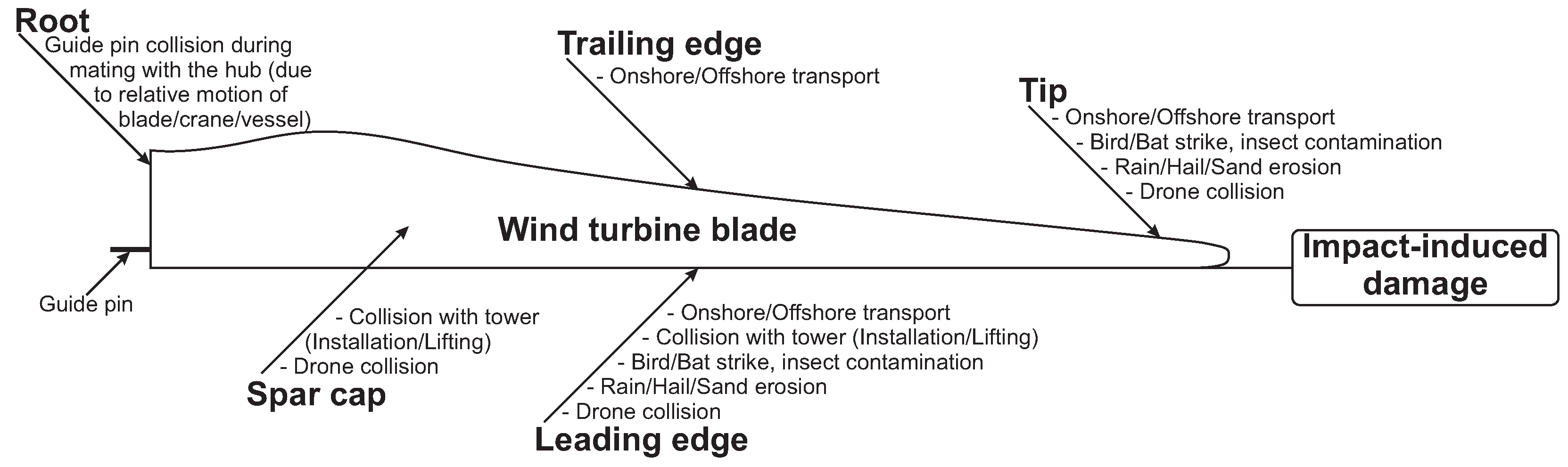
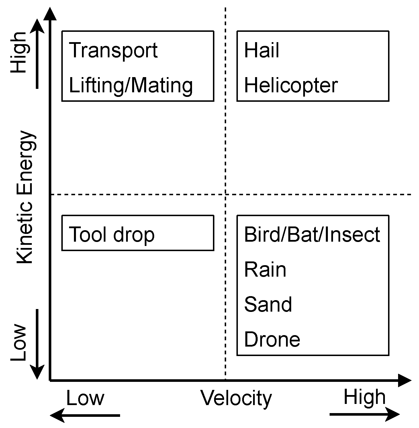

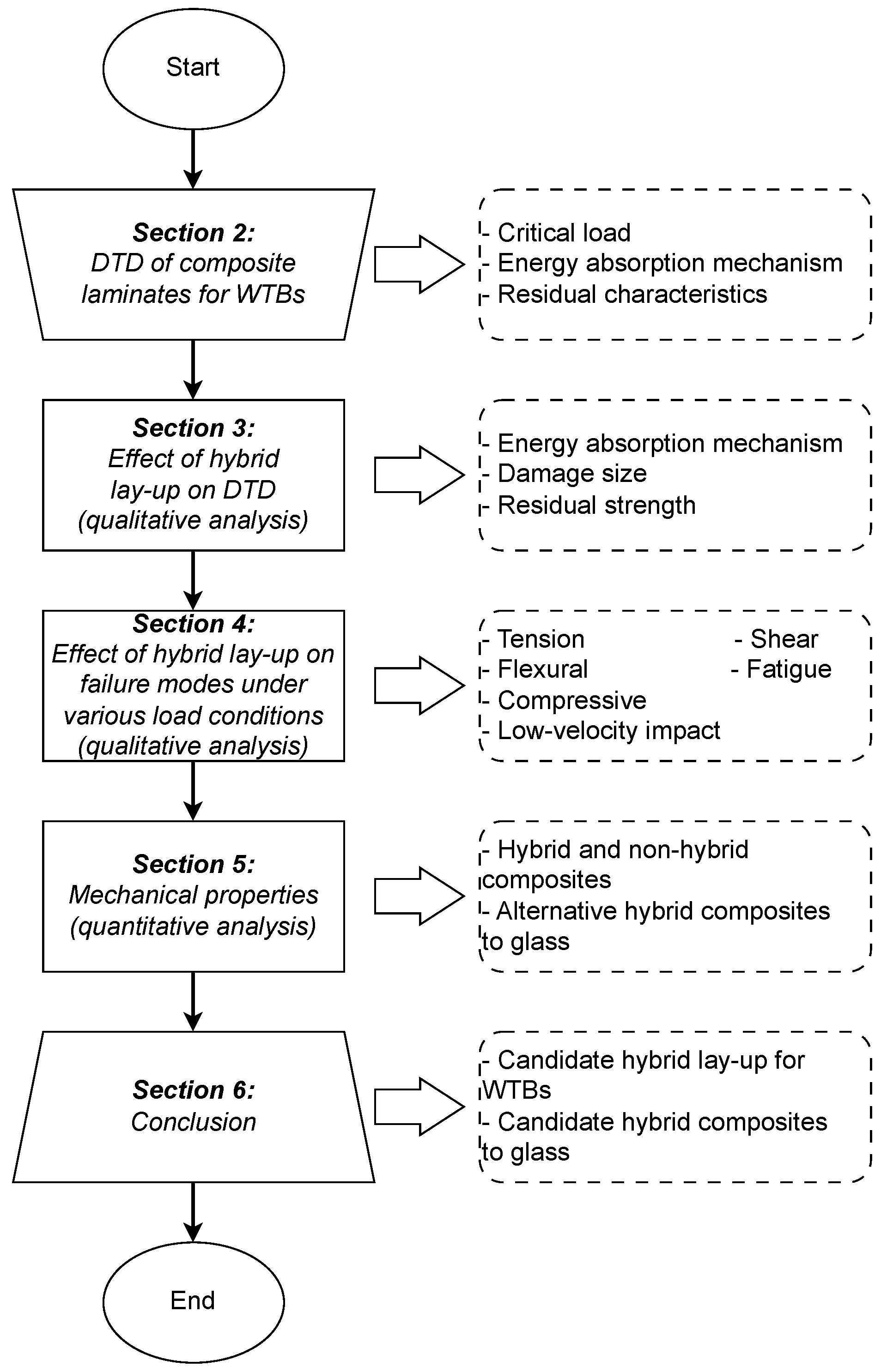

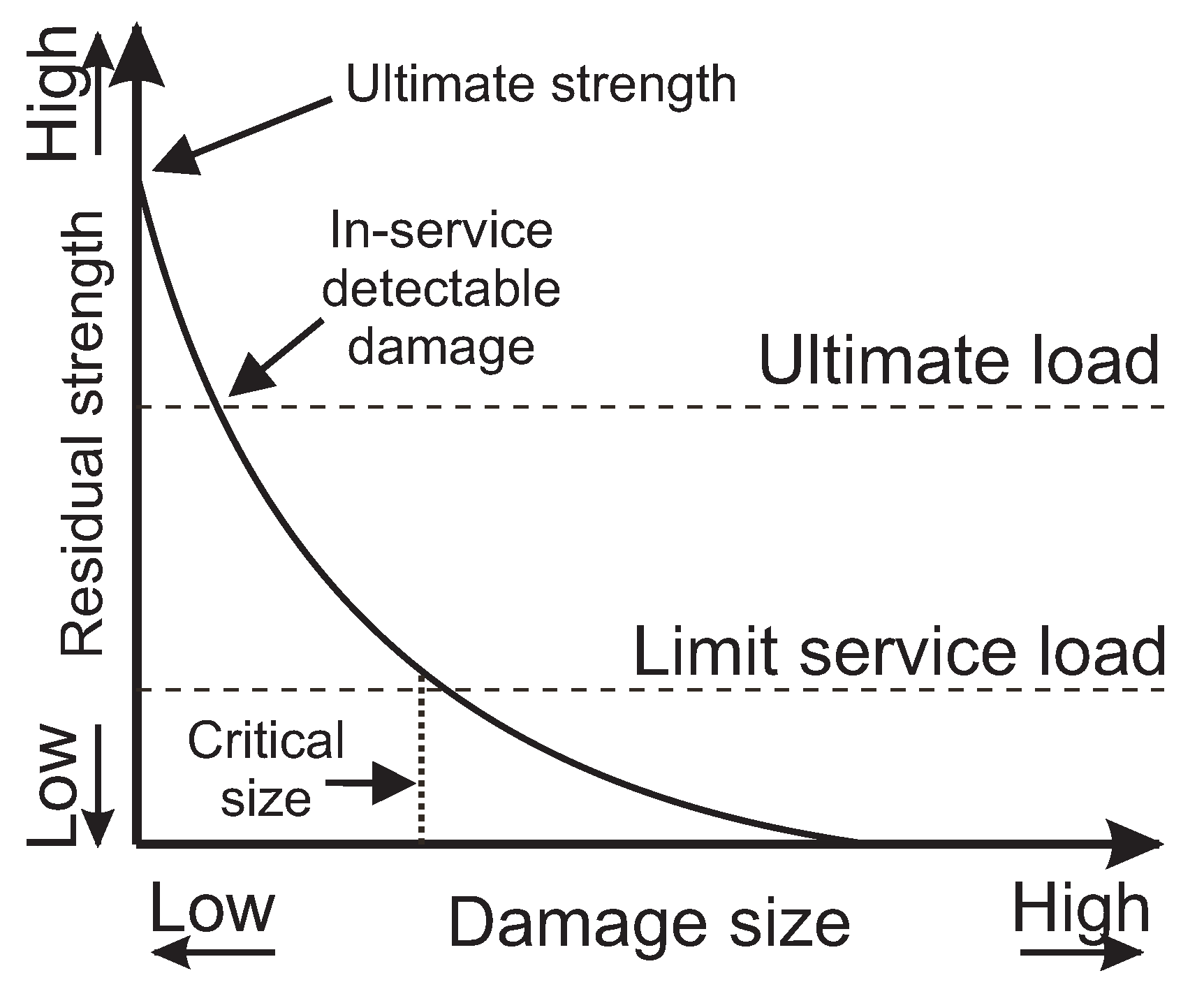
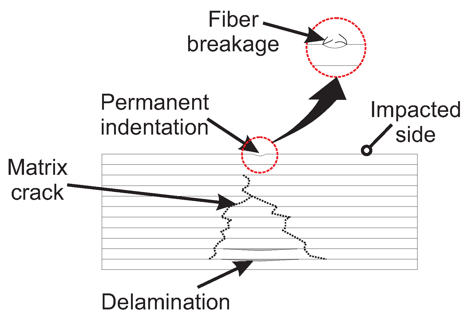
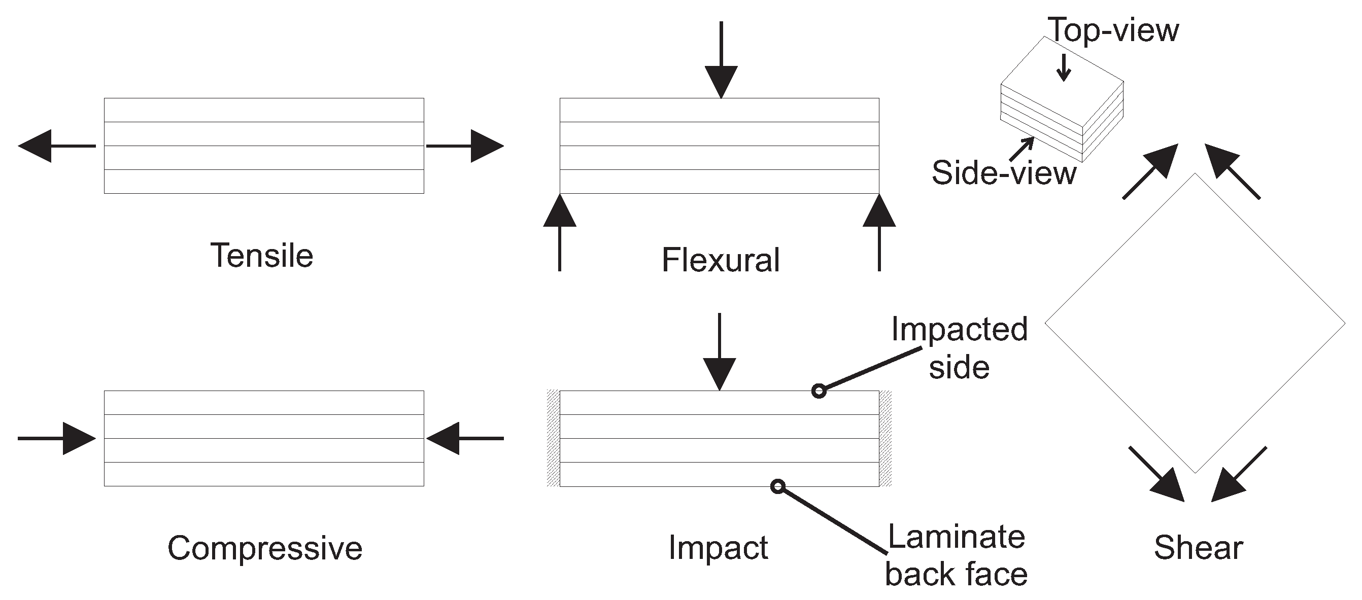

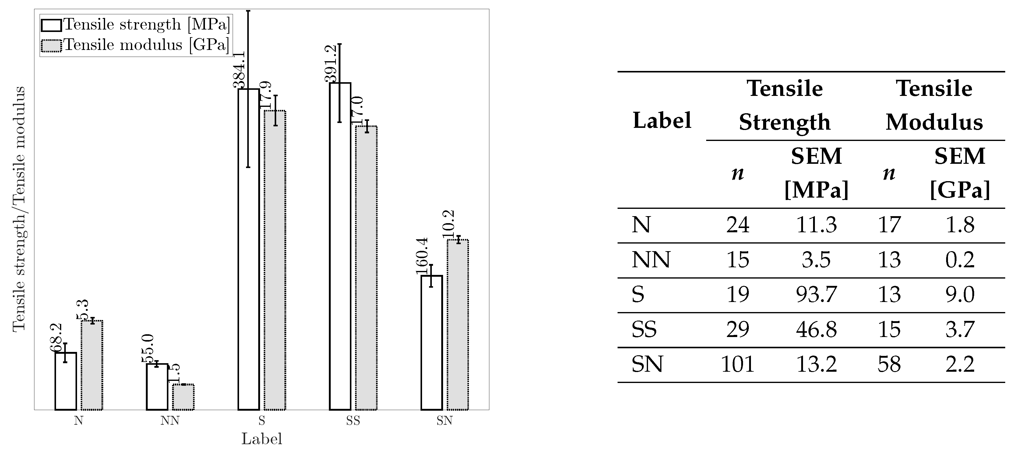


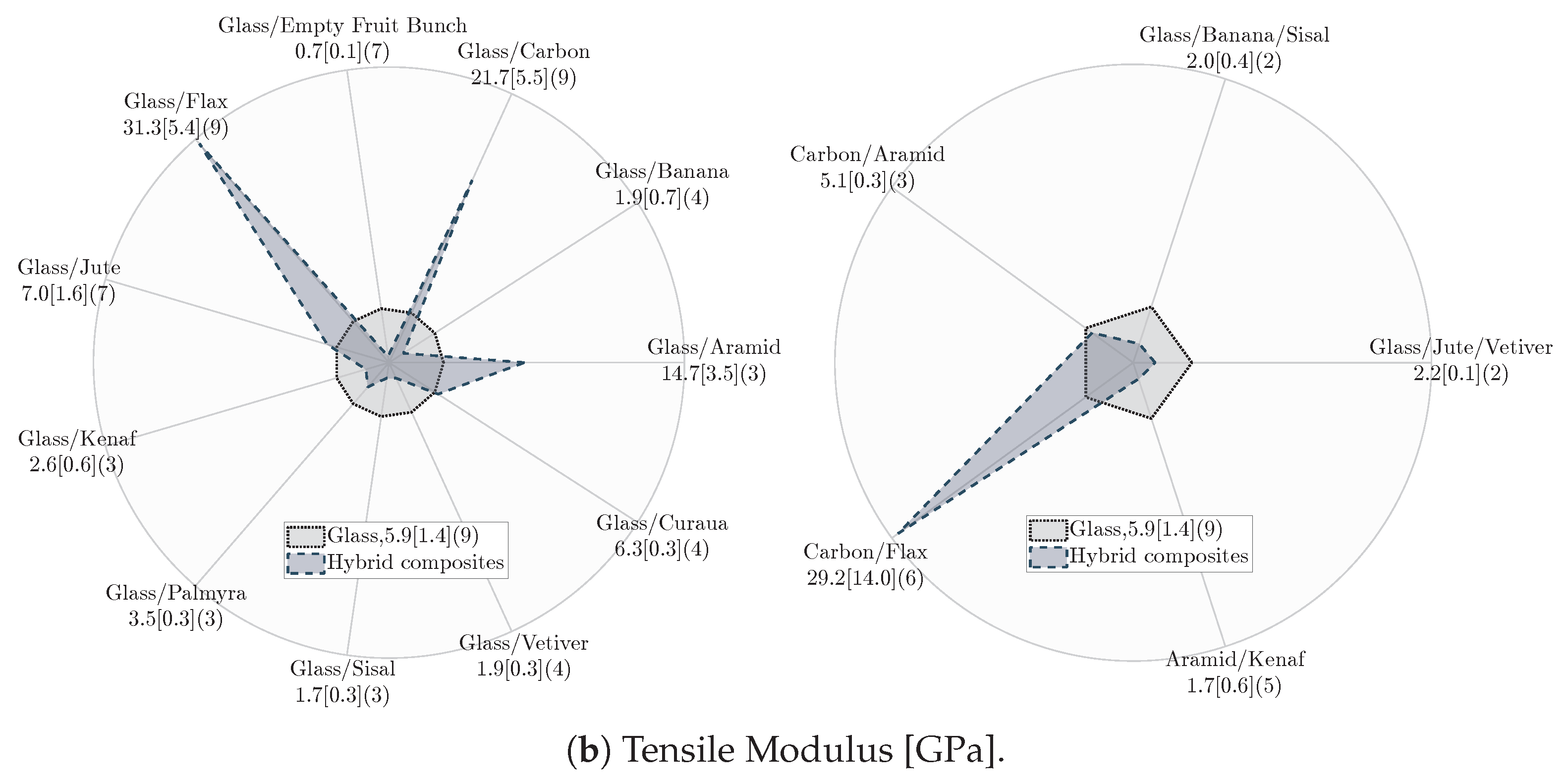
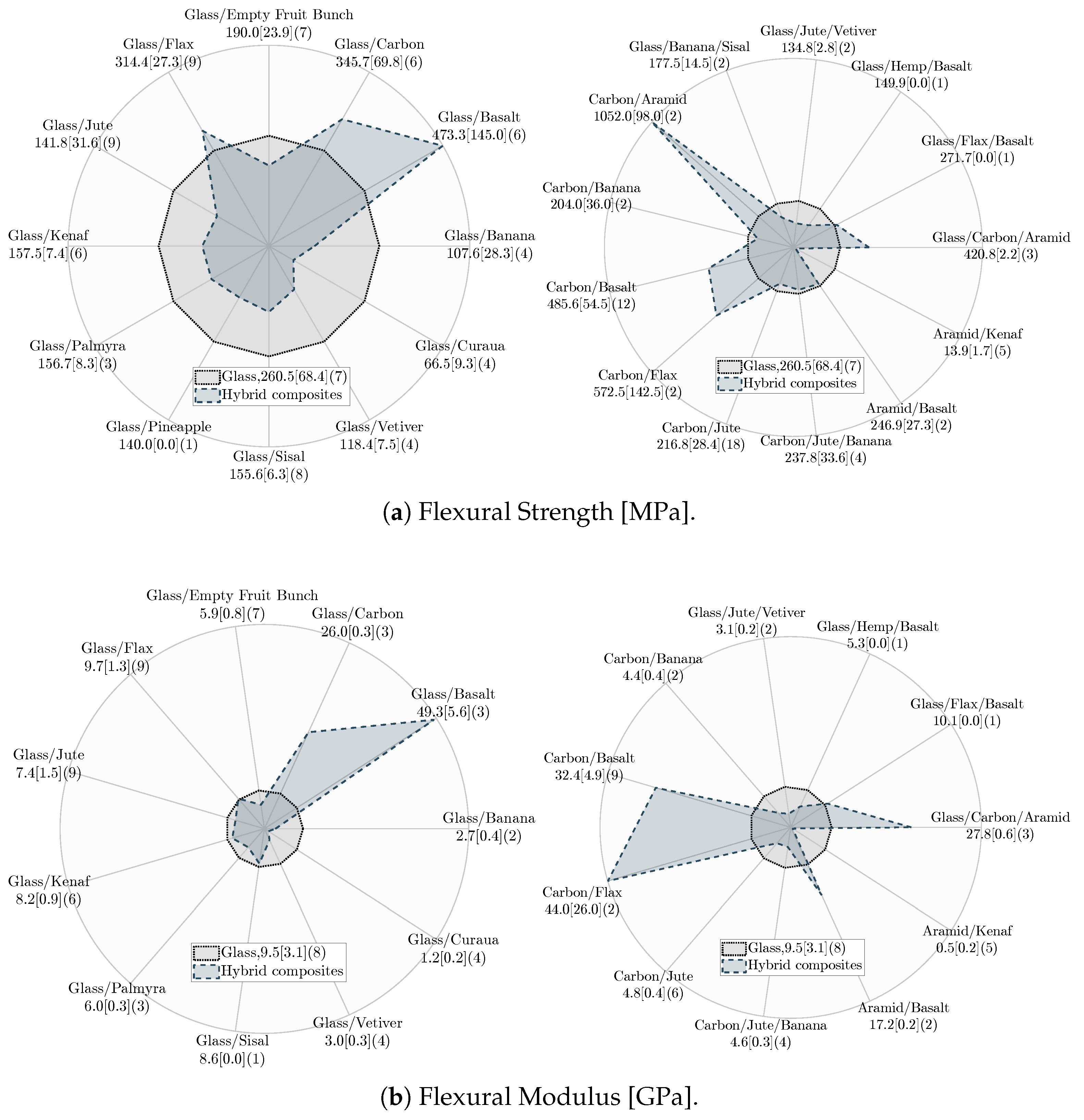
| Fiber | Stiffness * [GPa] | Elongation [%] |
|---|---|---|
| Aramid | 60 | 2.5–3.7 |
| Carbon | 240–425 | 1.4–1.8 |
| E-glass | 73 | 2.5 |
| Flax | 27.6 | 2.7–3.2 |
| Sisal | 9.4–22 | 3–7 |
| Lay-Up | Energy Absorption Mechanism | Damage Size | Residual Flexural Strength | Residual Compressive Strength | Overall Favorability for WTBs |
|---|---|---|---|---|---|
| A | High | Smaller than lay-up B | Medium (susceptible to long delamination on tension side) | Medium (better buckling resistance than lay-up B due to outer HE-LS fiber support) | High |
| B | Low | Larger than lay-up A | Low (prone to delamination-driven buckling on compression side) | Low (lack of buckling resistance mechanism) | Low |
| C | Low | Smaller than lay-up B | High (limited delamination due to intercalated lay-up) | Medium (enhanced buckling resistance) | Medium |
| D | Medium | Smaller than lay-up C | High (Similar concerns as lay-up C) | Medium (Similar concerns as lay-up C) | High |
| E | Medium | N/A | Low (susceptible to delamination at the interface of dissimilar fibers and fiber failure at laminate’s back face) | Low (risk of catastrophic failure †) | Low |
| F | Low | N/A | Low (risk of catastrophic failure *) | Low (risk of catastrophic failure †) | Low |
| Lay-Up | Tension Load | Flexural Load | Compressive Load | LVI | Overall Favorability for WTBs |
|---|---|---|---|---|---|
| A | High (delayed failure by fiber bridging) | High (placement of HE-LS fibers on the outermost) | High (buckling-resistance support for LE-HS fibers) | High (placement of HE-LS fiber on laminate’s back face, mitigate LE-HS fiber breakage) | High (especially if progressive failure and impact resistance are crucial) |
| B | Low (prone to catastrophic failure due to lack of damage-arresting features) | Low (susceptible to buckling on the compression side) | Low (prone to catastrophic failure due to lack of buckling-resistance support for LE-HS fibers) | Low (susceptible to fiber breakage on impacted side) | Low (risk of catastrophic failure) |
| C | Medium (prone to catastrophic failure due to more failure interface than lay-up A and high- stress regions) | Medium (placement of HE-LS fiber on tension side) | Medium (partially buckling- resistance support for LE-HS fibers) | Low (similar concerns as lay-up B) | Low (requires additional design considerations under LVI) |
| D | Medium (similar concerns as lay-up C) | Medium (placement of HE-LS fiber on compression side) | Medium (similar concerns as lay-up C) | High (enhanced damage- arresting features due to intercalated lay-up) | Medium (Limited performance under tensile, flexural, and compressive loads) |
| E | Medium (less prone to premature failure at the interface and induced high-stress regions) | Medium (risk of crack propagation due to LE-HS fiber failure on tension side) | Low (similar concerns as lay-up B) | Medium (sudden stress transfer to HE-LS fibers due to LE-HS fiber failure on tension side) | Low (requires buckling- resistance considerations for compressive load) |
| F | Medium (similar concerns as lay-up E) | Low (risk of catastrophic failure, early buckling of LE-HS fiber) | Low (similar concerns as lay-up B) | Low (similar concerns as lay-up B) | Low (similar concerns as lay-up B) |
| Composite | Baseline for Comparison | Average FVF [%] | Tensile Strength (Difference to Baseline [%]) | Tensile Modulus (Difference to Baseline [%]) | Flexural Strength (Difference to Baseline [%]) | Flexural Modulus (Difference to Baseline [%]) |
|---|---|---|---|---|---|---|
| N | - | 33 | - | - | - | - |
| NN | N | 33 | −19 | −72 | −25 | −53 |
| SN | N | 35 * | +135 | +91 | +72 | +38 |
| S | - | 39 | - | - | - | - |
| SN | S | 35 * | −58 | −43 | −47 | −55 |
| SS | S | 58 | +2 | −5 | +13 | +3 |
| Hybrid Composite | Baseline for Comparison | Tensile Strength | Tensile Modulus | Flexural Strength | Flexural Modulus |
|---|---|---|---|---|---|
| NN | N | − | − | − | − |
| SN | N | + | + | + | + |
| SN | S | − | − | − | − |
| SS | S | ∼ | ∼ | + | ∼ |
| Label | Hybrid Composite | Tensile Strength | Tensile Modulus | Flexural Strength | Flexural Modulus | Total Score |
|---|---|---|---|---|---|---|
| SS | Glass/Carbon | 1 | 1 | 1 | 1 | 4 |
| SN | Carbon/Flax | 1 | 1 | 1 | 1 | 4 |
| SN | Glass/Flax | 1 | 1 | 1 | 1 | 4 |
| SS | Carbon/Aramid | 1 | 0 | 1 | N/A | 2 |
| SN | Carbon/Basalt | 0 | N/A | 1 | 1 | 2 |
| SS | Glass/Aramid | 1 | 1 | N/A | N/A | 2 |
| SN | Glass/Basalt | 0 | N/A | 1 | 1 | 2 |
| SS | Glass/Carbon/Aramid | N/A | N/A | 1 | 1 | 2 |
| SN | Glass/Flax/Basalt | N/A | N/A | 1 | 1 | 2 |
| SN | Aramid/Basalt | N/A | N/A | 0 | 1 | 1 |
| SN | Glass/Curaua | 0 | 1 | 0 | 0 | 1 |
| SN | Carbon/Jute | 1 | N/A | 0 | 0 | 1 |
| SN | Carbon/Jute/Banana | 1 | N/A | 0 | 0 | 1 |
| SN | Glass/Jute | 0 | 1 | 0 | 0 | 1 |
| SN | Aramid/Kenaf | 0 | 0 | 0 | 0 | 0 |
| SN | Carbon/Banana | 0 | N/A | 0 | 0 | 0 |
| SN | Glass/Bamboo | 0 | N/A | N/A | N/A | 0 |
| SN | Glass/Banana | 0 | 0 | 0 | 0 | 0 |
| SN | Glass/Empty Fruit Bunch | 0 | 0 | 0 | 0 | 0 |
| SN | Glass/Kenaf | 0 | 0 | 0 | 0 | 0 |
| SN | Glass/Palmyra | 0 | 0 | 0 | 0 | 0 |
| SN | Glass/Pineapple | 0 | N/A | 0 | N/A | 0 |
| SN | Glass/Sisal | 0 | 0 | 0 | 0 | 0 |
| SN | Glass/Vetiver | 0 | 0 | 0 | 0 | 0 |
| SN | Glass/Kenaf/Bamboo | 0 | N/A | N/A | N/A | 0 |
| SN | Glass/Jute/Vetiver | 0 | 0 | 0 | 0 | 0 |
| SN | Glass/Hemp/Basalt | N/A | N/A | 0 | 0 | 0 |
| SN | Glass/Banana/Sisal | 0 | 0 | 0 | N/A | 0 |
Disclaimer/Publisher’s Note: The statements, opinions and data contained in all publications are solely those of the individual author(s) and contributor(s) and not of MDPI and/or the editor(s). MDPI and/or the editor(s) disclaim responsibility for any injury to people or property resulting from any ideas, methods, instructions or products referred to in the content. |
© 2025 by the authors. Licensee MDPI, Basel, Switzerland. This article is an open access article distributed under the terms and conditions of the Creative Commons Attribution (CC BY) license (https://creativecommons.org/licenses/by/4.0/).
Share and Cite
Baharvand, A.; Teuwen, J.J.E.; Shankar Verma, A. A Review of Damage Tolerance and Mechanical Behavior of Interlayer Hybrid Fiber Composites for Wind Turbine Blades. Materials 2025, 18, 2214. https://doi.org/10.3390/ma18102214
Baharvand A, Teuwen JJE, Shankar Verma A. A Review of Damage Tolerance and Mechanical Behavior of Interlayer Hybrid Fiber Composites for Wind Turbine Blades. Materials. 2025; 18(10):2214. https://doi.org/10.3390/ma18102214
Chicago/Turabian StyleBaharvand, Amir, Julie J. E. Teuwen, and Amrit Shankar Verma. 2025. "A Review of Damage Tolerance and Mechanical Behavior of Interlayer Hybrid Fiber Composites for Wind Turbine Blades" Materials 18, no. 10: 2214. https://doi.org/10.3390/ma18102214
APA StyleBaharvand, A., Teuwen, J. J. E., & Shankar Verma, A. (2025). A Review of Damage Tolerance and Mechanical Behavior of Interlayer Hybrid Fiber Composites for Wind Turbine Blades. Materials, 18(10), 2214. https://doi.org/10.3390/ma18102214