1. Introduction
Additive manufacturing (AM) processes, such as laser-based powder-bed fusion of metals (PBF-LB/M), enable the realization of complex topologies with variable stiffness and internal cavities, which can significantly enhance structural performance [
1,
2]. However, with increasing geometric complexity, manufacturing costs rise due to the need for additional support structures, rework, and longer production times [
3]. Additionally, the limited build space of AM machines constrains the maximum size of a single AM component that is manufacturable, affecting the feasibility of AM for various applications. To overcome these limitations and reduce manufacturing costs, part separation and subsequent joining of AM subcomponents can be an effective strategy [
4,
5]. Moreover, the freedom of design underlying AM processes is often needed only in specific regions of a structure. Thus, it can make sense to enhance the structure with non-AM components (i.e., fiber-reinforced composites) by means of a hybrid structure [
6,
7]. Adhesive bonding is a particularly promising joining technology in this context, as it adds minimal weight and does not restrict the geometry of the joining surfaces or the material of the adherends [
8,
9,
10,
11].
To ensure structural integrity, the adhesive joint design plays a crucial role [
12,
13]. This entails ensuring a sufficiently large adhesive surface area and preferably subjecting the adhesive to shear rather than peel stress (tensile stress perpendicular to the adhesive surface) [
12,
13,
14]. Adhesive joint designs can roughly be categorized into butt joints and lap joints. In butt joints, the substrates are simply joined end-to-end at their front surfaces. Due to the comparably small adhesive surface area and the occurrence of large peel stresses, this design is less common in structural applications [
15]. In lap joints, the joining surfaces of the substrates are overlapping and therefore provide an arbitrarily large adhesive surface area. Disadvantageous is the additional weight due to the material overlap, as well as the eccentric load application in combination with finite adherend stiffness, which causes pronounced adhesive stress increases at the overlap ends [
16]. As the stress increases initiate failure [
17], it is conceivable to increase the bearable load of the joint (bond strength) while maintaining a constant adhesive surface area by homogenizing the adhesive stress distribution and shifting the adhesive stress state towards pure shear through optimizing the geometry of the adherends.
Finite element (FE)-based genetic algorithm (GA) and topology optimization (TOP) approaches have already been applied to enhance bond strength in rectangular [
18,
19] and tubular [
12] single-lap joints (SLJs). These studies employ either a continuum mechanics approach with energy- or stress-based failure criteria or a fracture mechanics approach utilizing cohesive zone modeling (CZM) and a damage-based failure criterion. While previous TOP procedures neglect adhesive plasticity in the corresponding constitutive response, an essential factor in strength assessment [
20,
21], the GA approach accounts for debonding through a traction-separation law and considers adhesive plasticity via a Johnson–Cook plasticity model, making it the most suitable method in terms of strength assessment and failure prediction. However, this approach is computationally expensive and, as a result, fails to leverage the extensive design flexibility offered by additive manufacturing. Although all procedures demonstrate significant potential for increased bond strength, previous studies lack experimental validation.
Therefore, in this study, a computationally efficient solid isotropic material with penalization (SIMP) algorithm [
22] and implicit FE analysis are used to optimize the topology of an additively manufactured laser-based powder-bed-fusion aluminum alloy AlSi10Mg (PBF-LB/M/AlSi10Mg) sleeve, which is part of an axially loaded single-lap tubular joint (SLTJ) adhesively bonded to an inner carbon fiber-reinforced composite (CFRC) tube using a highly ductile two-component (2C) structural adhesive based on epoxy resin (Scotch-Weld DP490, 3M Deutschland, Neuss, Germany). This adhesive was chosen because it is specifically formulated for bonding of metal and composite materials and is widely used in industrial applications due to its facile processability and high strength characteristics. The joint is modeled using a continuum mechanics approach, where adhesive plasticity is accounted for by means of a multilinear elastoplastic material model. To increase the bond strength of the joint, the element density of the PBF-LB/AlSi10Mg sleeve is iteratively adjusted to achieve homogeneous adhesive shear stress. The optimum sleeve topology found is redesigned considering manufacturing constraints of the PBF-LB/M additive manufacturing process. To quantify the resulting adhesive stress state, non-linear FE analysis is conducted at different tensile loads with tubular joints featuring optimum, redesigned, and non-optimized cylindrical reference sleeves. Subsequently, redesigned and cylindrical reference sleeves are manufactured and adhesively bonded to CFRC tubes to experimentally quantify the difference in bond strength by means of static tensile and fatigue testing.
The main objective of this study is to investigate the extent to which the geometric design freedom offered by additive manufacturing can contribute to improving the bond strength of an axially loaded SLTJ between a CRFC tube and PBF-LB/AlSi10Mg sleeve, when the topology of the sleeve is subjected to FE-based SIMP optimization. Distinct features of this investigation include the incorporation of adhesive plasticity into the optimization process, as well as experimental strength validation.
2. Materials and Methods
The axially loaded SLTJ subjected to implicit FE-based TOP comprises an inner adherend, which is a roll-wrapped unidirectional CFRC tube having an outer diameter of
and a wall thickness of
, as well as an outer adherend, which is an additively manufactured PBF-LB/M/AlSi10Mg sleeve having an inner diameter of
. The adherends are joined by an interstitial layer of a two-component epoxy-based (2C-Epoxy) structural adhesive (Scotch-Weld DP490, 3M Deutschland, Neuss, Germany), each having a thickness of
. This approach assumes ideal dimensional accuracy and perfect concentric alignment of the adherends. The outer adherend is divided into the non-design space (NDS) having an outer diameter of
and the design space (DS) having an outer diameter of
. During the optimization process, the element density of the DS is the variable to be altered to meet the objective function of the SIMP optimization (
Figure 1).
The overlap between the inner and outer adherend is , leading to an adhesive surface area of . To minimize computational effort, only a segment of the rotationally symmetric joint was discretized using CHEXA20 second-order solid elements (outer adherend and adhesive), and CQUAD8 second-order shell elements (inner adherend), which were assigned to a cylindrical analysis coordinate system. To enforce rotational symmetry, the azimuthal displacement of elemental nodes at the symmetry faces was constrained to . The adhesive layer is represented by eight elements in the radial direction () and 120 elements in the longitudinal direction (), resulting in element edge lengths of (radially) and (longitudinally). The average element edge length in the DS of the AlSi10Mg sleeve is . The contacts between adjacent components are modelled continuously by merging coincident elemental nodes at the component interfaces, thereby assuming perfect adhesion between the adhesive and the adherends and neglecting the influence of surface roughness. To replicate the boundary conditions of the pursuing tensile tests, rigid clamping is applied by fixing all degrees of freedom at nodes on the top surface of the clamping shoulder (bolt head seating according to the tensile test setup detailed below), and a longitudinal tensile force is introduced at nodes on the top surface of the CFRC tube using a one-dimensional rigid body element (1D-RBE). As part of the TOP process, the longitudinal tensile force was set to . Given the reduced adhesive surface area of of the segment considered, this results in a nominal adhesive shear stress of . The total number of degrees of freedom in the FE model amounts to 564,670.
The material parameters utilized for modeling the structural mechanical behavior of the components are shown in
Table 1.
As the von Mises equivalent stress in the AlSi10Mg sleeve must not exceed the yield strength of
, it is reasonable to define only linear-elastic material parameters. Neglecting the build-direction-induced anisotropy intrinsic to the PBF-LB/M process is permissible, as the material parameters defined in
Table 1 were determined from vertically oriented tensile samples [
23], consistent with the intended build direction of the AlSi10Mg sleeves. The CFRC tube exhibits linear-elastic material behavior up to the tensile strength of
[
24]. Considering a nominal tensile stress in the CFRC tube of
(corresponding to
), the constitutive response of the CFRC tube is fully characterized by specifying linear-elastic material parameters. The CFRC tube laminate is composed of ten stacked unidirectional plies, each having a thickness of
. The fibers extend parallel to the longitudinal (z) direction of the tube. By modeling the laminate on a ply basis, the layer stack and fiber orientation can be represented by single shell elements. This requires specifying the orthotropic material parameters of a single unidirectional ply, along with the orientation and order of the plies. The material parameters provided in
Table 1 refer to a unidirectional ply with high tenacity (HT) fibers and a fiber content of
according to [
24]. Since the 2C-Epoxy adhesive exhibits non-linear stress–strain behavior far below the ultimate strength of
, pure consideration of elasticity is insufficient for structural–mechanical analysis [
20,
21]. To account for the adhesive’s plasticity, a multilinear elastoplastic material model is employed in [
25]. In doing so, the technical stress–strain curve obtained from static tensile tests using adhesive bulk samples according to [
26] is approximated using multiple regression lines, and the deflection points of the locally linearized stress–strain curve serve as input parameters for the material model. By assuming elastic and plastic isotropy, the structural–mechanical behavior of the 2C-Epoxy adhesive is fully characterized by additionally specifying the shear modulus G, which was determined through torsion testing of butt-bonded hollow cylinders [
25].
The optimization function considered by the SIMP algorithm is defined by an optimization target and optimization constraints [
22]. As FE-based analysis of an axially loaded SLTJ using CZM shows that bonding failure, following a bi-linear traction-separation law, correlates with the maximum first principal stress adjacent to the bonding interface [
12], the optimization target is set to minimize the first principal stress
within the adhesive component. Considering a reference value for the first principal stress of
, pure adhesive shear and minimum peel stress are aimed for. Optimization constraints regarding the aluminum sleeve (DS and NDS) include a maximum von Mises equivalent stress of
and a mass reduction of
in the DS. To meet the objective function criteria, the SIMP algorithm iteratively adjusts the element density (
) of each individual element in the DS of the PBF-LB/AlSi10Mg sleeve. The
can vary in the range of
, where
corresponds to no material and
corresponds to solid material. Since the penalization parameter of the SIMP algorithm is set to
, intermediate element densities (
) are penalized, promoting a clear distinction between solid and void regions. The optimization process converges when the relative change in the objective function between two consecutive iterations falls below the threshold of
.
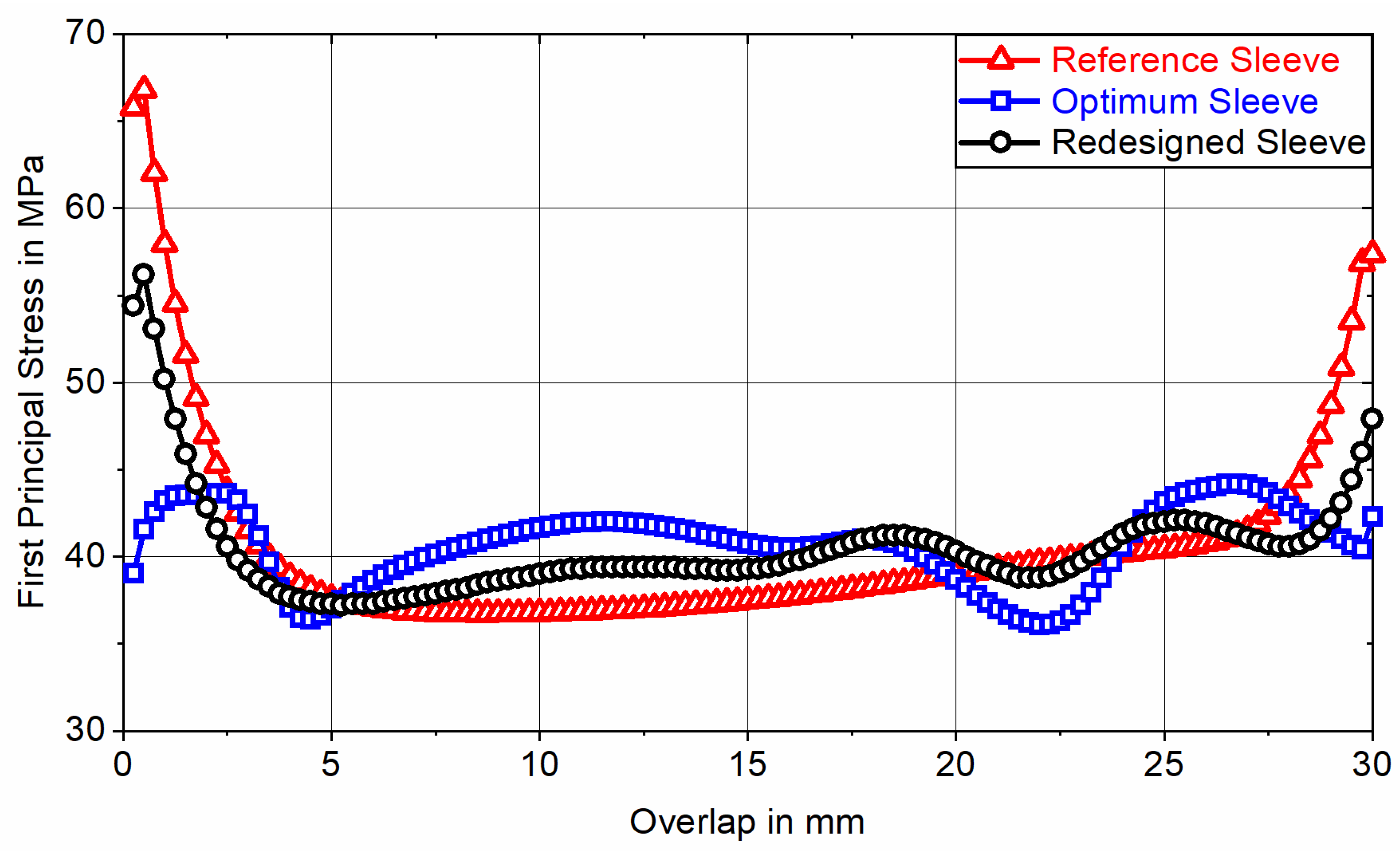
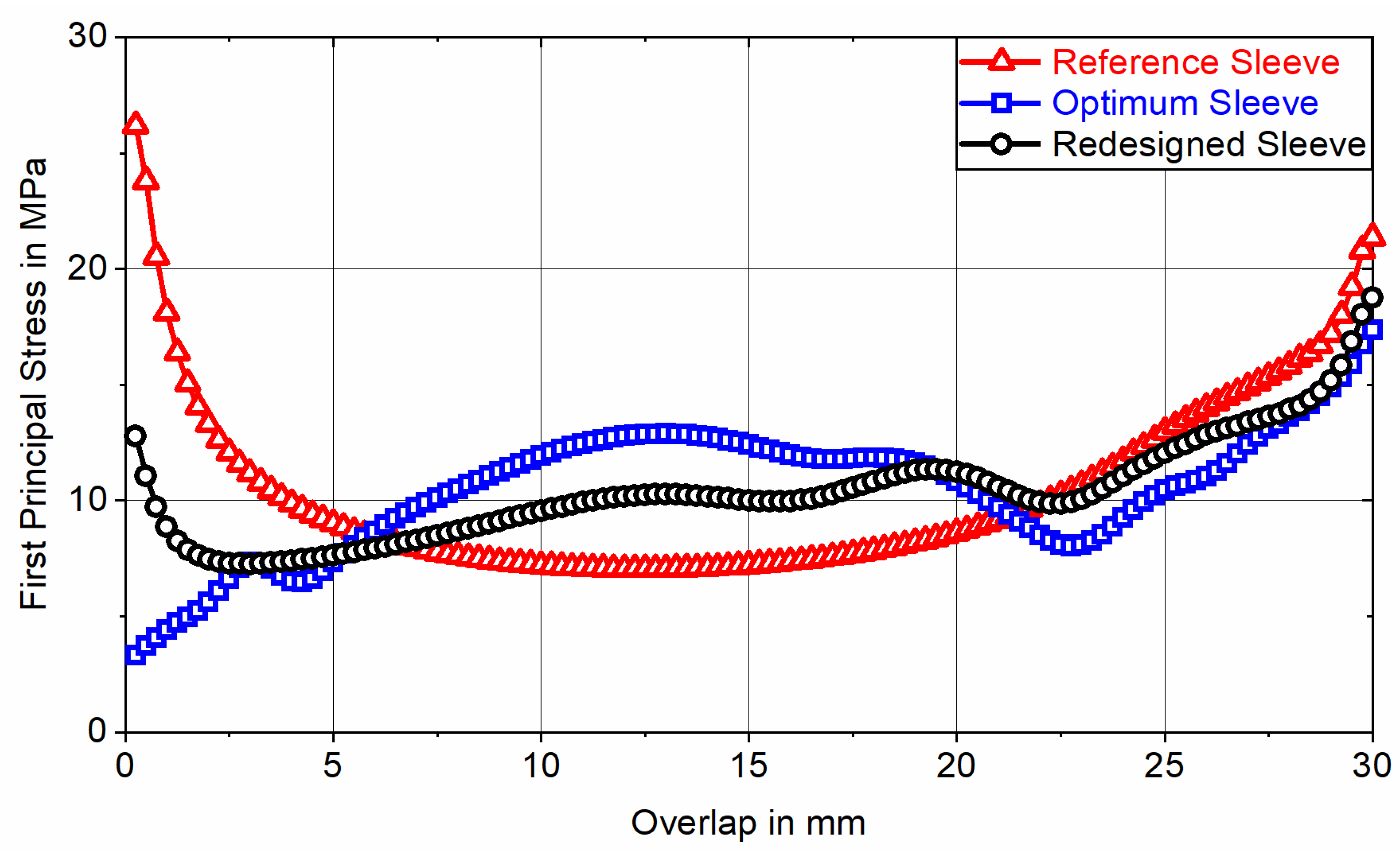
To quantify the resulting adhesive stress state, the optimum sleeve topology is FE-analyzed at tensile loads of
and
, corresponding to nominal adhesive shear stresses of
(nonlinear) and
(linear), and the first principal stress is evaluated for all 120 elements representing the adhesive layer along the overlap (
-direction) at adhesive mid-thickness (in the fifth of eight element rows representing the adhesive layer in the positive
-direction). For classification, this result is contrasted with the course of the first principal stress induced by a redesigned sleeve and a non-optimized cylindrical reference sleeve having an outer diameter of
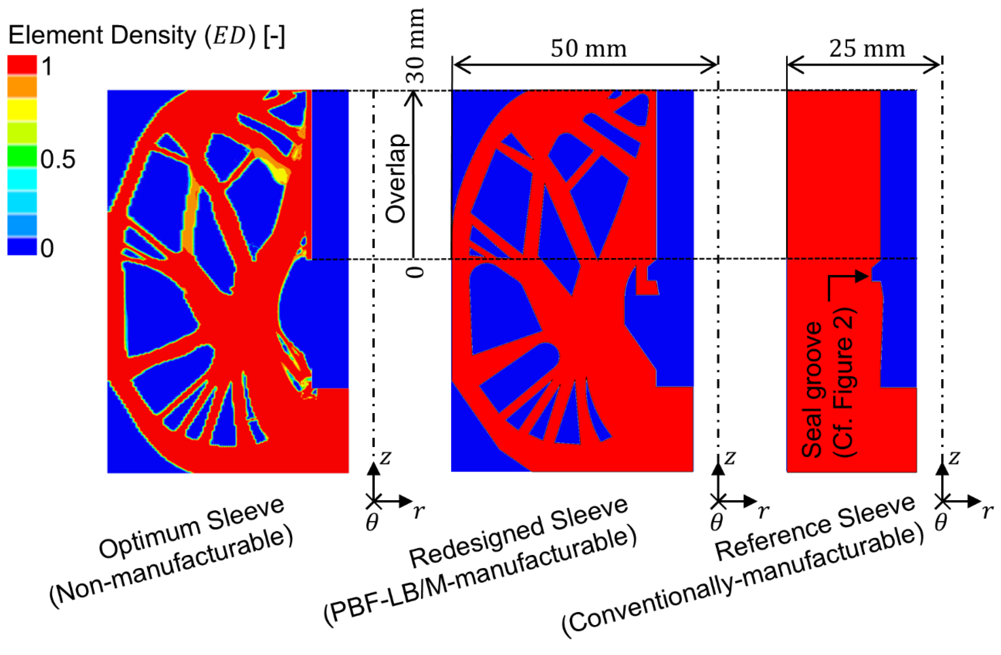
. The redesigned sleeve is based on the optimum topology while considering manufacturing constraints related to the PBF-LB/M process. The redesign was generated based on the contour plot of the optimum ED using computer-aided design (CAD) software (CATIA V5-6R2016, Dassault Systèmes, Vélizy-Villacoublay, France). In doing so, the contours depicted were resketched (
neglected) and abstracted to comply with a minimum overhang angle of
and a minimum wall thickness of
[
2,
27]. Subsequently, the sketch was rotated over an angle of
to form a solid body, which served as a basis for the ensuing FE analysis. Both the FE-based stress analyses and the TOP procedure were conducted using commercially available FE software (HyperWorks 2021.2, Altair Engineering, Troy, MI, USA) with the OptiStruct solver.
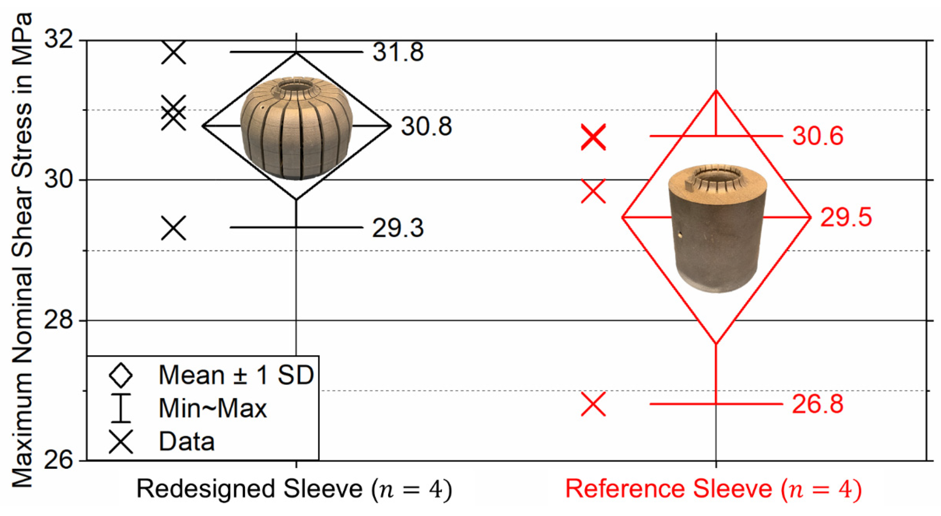
To experimentally quantify the bond strength of the redesigned and reference sleeves, static tensile and fatigue tests were performed using a total of
bonded tensile samples. These include four redesigned and four cylindrical reference sleeves for conducting static tensile tests, as well as eight redesigned sleeves and eight cylindrical reference sleeves for conducting fatigue tests. The sleeves were manufactured using a DMG MORI LASERTEC 30 SLM 2nd Generation (Bielefeld, Germany) PBF-LB/M additive manufacturing machine. The associated manufacturing parameters are depicted in
Table 2.
Commercially available AlSi10Mg powder (EN-AC 43000, as specified in [
28]) with a particle size between
and
was used throughout. To suppress influences on the surface roughness caused by varying component orientation and to ensure consistency with the material parameters provided in
Table 1, the AlSi10Mg sleeves were manufactured vertically oriented (longitudinal axis perpendicular to the build plate). The redesigned sleeve features 20 equidistant radially symmetric slots with a slot opening angle of
to facilitate the removal of residual powder from the internal cavities. The maximum and minimum inner diameters of the
sleeves were determined to be
and
by optical measurement using a 3D laser scanning microscope (Keyence, VK-X 3000). Commercially available roll-wrapped unidirectional CFRC tubes with nominal dimensions of
were used as inner adherends. They offer an HT fiber content of
and a ground outer surface finish. The tubes’ maximum and minimum inner diameters were determined to be
and
using a digital outside micrometer (Absolute Digimatic 2, Mitutoyo, Kawasaki, Japan). A 2C-Epoxy structural adhesive (Scotch-Weld DP490, 3M Deutschland, Neuss, Germany) was used to adhesively bond the inner and outer adherend. By assuming perfect concentric alignment of the adherends, based on the measured inner sleeve and outer tube diameters, the actual adhesive layer thickness ranges from
to
with an arithmetic mean of
.
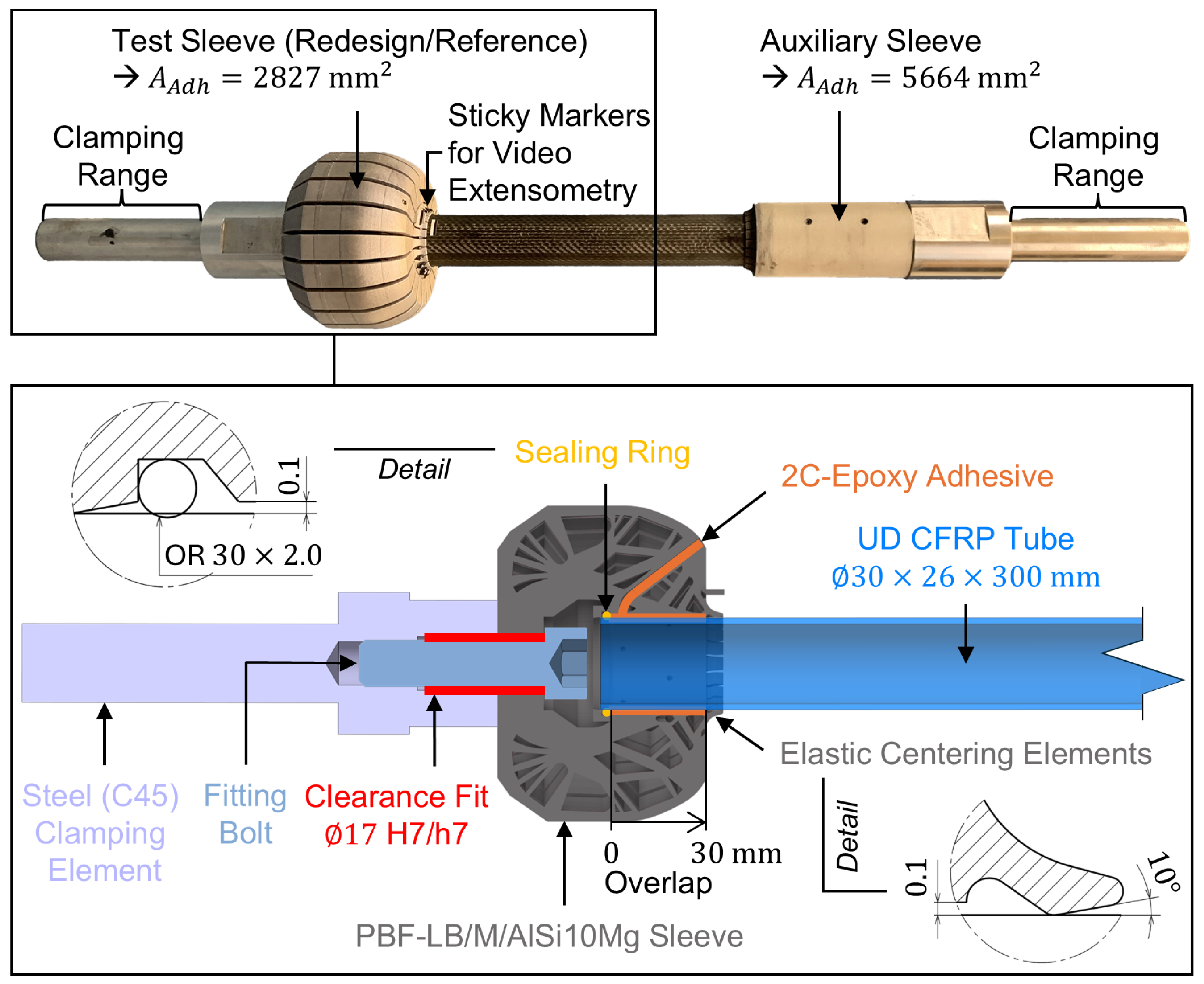
Figure 2 shows a schematic of a test sleeve (bottom) and an exemplary entire tensile test sample (top).
The preceding steps up to the completion of the bonded tensile test sample were as follows: After separating the de-powdered sleeves from the build plate using a band saw, the bottom surface was faced on a lathe. Then, the adhesive surface of the sleeves was grid-blasted with corundum (F200), cleaned in an ultrasonic bath with isopropanol, rinsed, and dried. Subsequently, the sleeves were bolted to steel clamping elements using a special fitting bolt to ensure concentric alignment. Next, a sealing ring (OR ) was inserted into a designated groove within the sleeve, followed by the CFRC tube, which is concentrically aligned with the sleeve by the sealing ring at the bottom and elastic centering elements integrated at the top of the sleeve.
The adhesive surface of the CFRC tube was mechanically treated using abrasive fleece (Scotch-Brite CF-HP 7447, 3M Deutschland, Neuss, Germany), followed by cleaning with isopropanol before being inserted into the sleeve. No bonding agent was used. Then, the adhesive was injected, filling the adhesive fill gap between the adherends according to [
29,
30]. For hardening, the samples were stored in a climatic chamber for two hours at
and then conditioned to the standard climate (
) for at least
h. For clamping the CFRC tube in the test machine, a cylindrical auxiliary sleeve overlapping the tube by
was employed. Given the doubled adhesive surface area relative to the test sleeve, failure of the auxiliary sleeve’s adhesive bond is highly improbable.
The static tensile tests were carried out using a
servo-hydraulic tensile-testing machine (Schenck-Trebel, Carl Schenck, Darmstadt, Germany). The bonded samples were fixed over a clamping range of
using wedge grips. To steadily increase the load on the joint, the testing machine was operated in a displacement controlled manner with a constant test speed of
[
31]. The test results are documented in the form of nominal shear stress versus machine stroke diagrams, from which the maximum measured nominal adhesive shear stress (static bond strength) is determined by relating the maximum force measured to the sleeve’s adhesive surface area,
. A video extensometer (RTSS, LIMESS, Krefeld, Germany) was used to measure the
-strain between two high-contrast sticky markers applied to the lateral surfaces of the CFRC tube and the AlSi10Mg sleeves (see
Figure 2, top). To validate the FE model, the corresponding
-strain was determined by means of nonlinear FE analysis by evaluating the difference in
-displacement between elemental nodes positioned at the same locations as the contrast lines of the sticky markers. Up to a nominal shear stress of
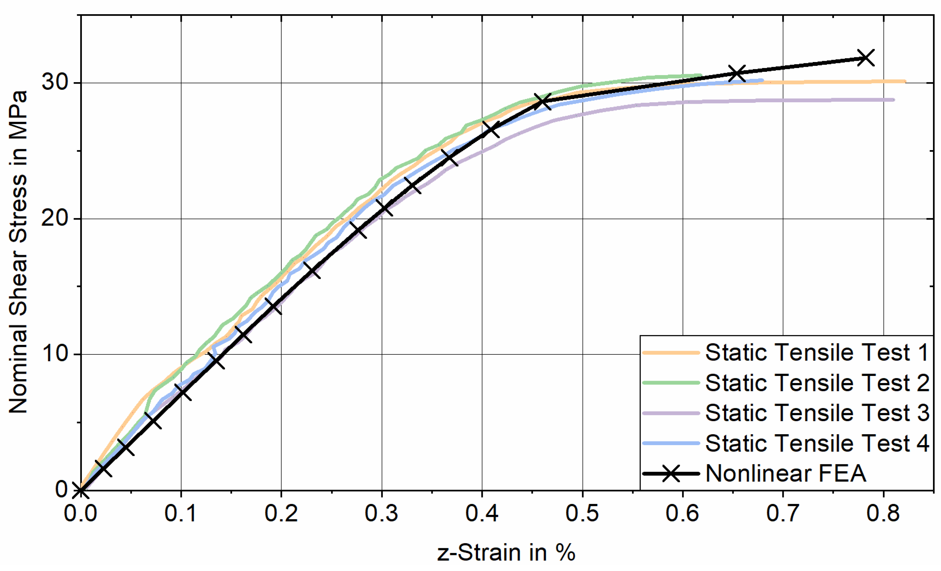
, the stress–strain response obtained from tensile testing aligns well with the results of the nonlinear FE analysis for joints featuring cylindrical reference sleeves, supporting the validity of the FE model (see
Appendix A).
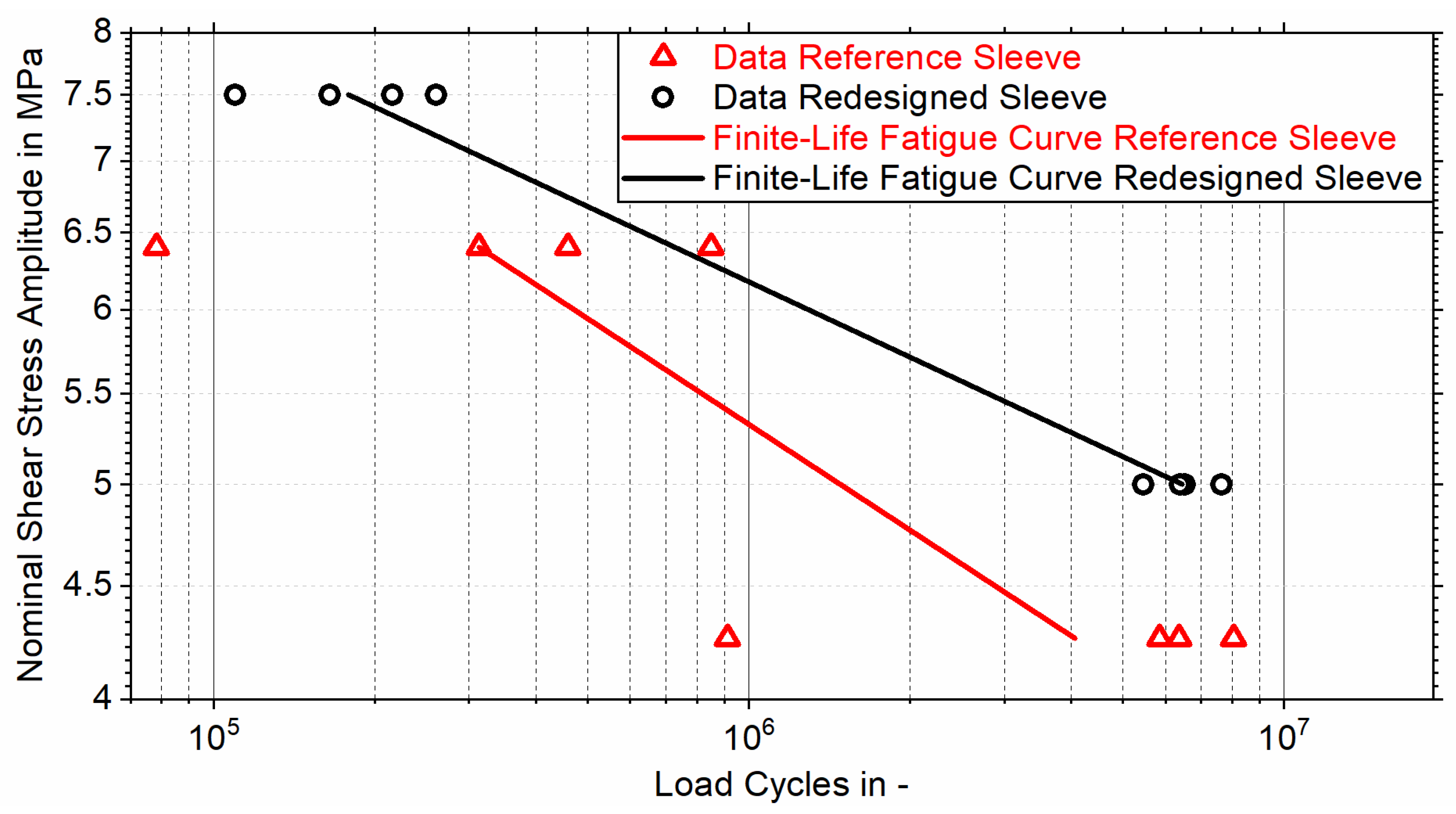
The fatigue strength of the joints was determined through pulsating tensile fatigue tests using a
SincoTec Power Swing (Clausthal-Zellerfeld, Germany) electromechanical resonance testing machine, where eight bonded tensile samples with redesigned test sleeves were subjected to cyclic tensile loading with sinusoidal progression at nominal shear stress amplitudes of
or
, while eight bonded tensile samples with reference test sleeves were subjected to nominal shear stress amplitudes of
and
. All tests were conducted with identical stress ratios of
and test (resonance) frequencies ranging from
to
. Four tensile samples were subjected to each stress amplitude, and the number of load cycles endured was counted until the maximum endurable stress of the test sleeve’s adhesive bond dropped below
of the respective maximum stress
. The load amplitudes were determined during preliminary tests to ensure that the number of endurable load cycles ranges from
to
. Accordingly, the results can be presented in a Wöhler (S-N) diagram, where a finite-life fatigue curve for each sleeve is evaluated at a
failure probability using the horizontal method [
32].


