Abstract
The earth pressure acting on soilbag-reinforced retaining structures subjected to surcharge loads under non-limited states is crucial for designing these structures. In this study, mode tests on soilbag-reinforced retaining walls were conducted to the earth pressure of the wall subjected to surcharge loads. The findings from these tests reveal a non-linear distribution of lateral earth pressure on the wall when subjected to surcharge loads in non-limited states, with an observed escalation in pressure corresponding to increased surcharge loads. Insights from the tests facilitated the development of a predictive method for estimating lateral pressure on soilbag-reinforced retaining walls under similar conditions, and its performance was fully validated by the model tests. Furthermore, the impact of the geometric dimensions and material properties of the soilbags on the earth pressure distribution was examined using the proposed method.
Keywords:
geosynthetics; soilbag; retaining wall; earth pressure; surcharge loads; non-limited state 1. Introduction
Geosynthetic materials, such as geotextiles, geomembranes, and geogrids, are often made from recycled or recyclable materials. Their use in civil engineering projects helps in reducing the dependency on natural resources and minimizes environmental footprints [1,2,3,4,5,6]. Soilbags are a form of application of geosynthetic materials in civil engineering. Traditionally, due to their limited durability, soilbags are primarily employed in constructing temporary embankments during floods and for building temporary structures in post-disaster scenarios [7]. However, following aging tests conducted by Matsuoka and Liu [8], it was asserted that soilbags exhibit enhanced durability when manufactured with anti-aging agents in woven bags. This advancement has led to the gradual adoption of these enhanced soilbags in permanent infrastructure projects, including reinforcing foundations [9], building retaining structures [10], and stabilizing slopes [11].
The soilbag-reinforced retaining structure is an important form in which soilbags are applied in engineering, and several application cases and the good performance of this new type of structure have been reported [12]. To establish well-supported design guidelines for scientifically engineering these structures, Fan et al. [10] explored the distribution of earth pressures behind soilbag-reinforced retaining walls through laboratory experiments and developed a method for analyzing the sliding stability of the wall based on the equilibrium of earth pressure and the interface resistance of soilbags. Wang et al. [13] investigated the effects of soilbag arrangements and tail length on the displacement and earth pressure of the wall. They proposed a method for estimating the wall’s safety using the upper-bound approach. Matsushima et al. [14] showcased many examples of soilbag-constructed retaining wall failure and found that one of the major drawbacks of this type of wall is the relatively low stability caused by slippage along the horizontal interface in between the adjacent soilbags, which results in a catastrophic failure. Addressing this, Liu et al. [15] conducted a series of lateral shear loading tests on a pile of three full-scale soilbags to examine the impact of inclined load on the shear strength of multi-layered soilbags. These studies collectively contribute valuable insights for designing soilbag-reinforced retaining structures.
In a large number of retaining structure projects, additional surcharge loads, such as those from vehicles and buildings, are often present on the surface of the backfill behind the structures. These loads negatively impact the stability of the retaining structure [16,17,18,19,20]. It is therefore essential to determine the earth pressure exerted on soilbag-reinforced retaining walls when subjected to such surcharge loads. However, existing research has primarily focused on soilbag-reinforced retaining walls under limit states [10,13]. In practical engineering situations, this state of limit equilibrium is often not reached, resulting in a non-limited state for the wall [21,22]. This divergence is attributed to factors such as the restricted movement of soilbags and the complex behavior of soil. As a result, there is a need for a more sophisticated approach to accurately estimate the active earth pressure on soilbag-reinforced retaining walls under surcharge loads in a non-limited state, to better mirror the actual conditions faced by these structures.
In this study, physical model tests were performed to investigate the earth pressure exerted on the soilbag-reinforced retaining wall subjected to surcharge loads under the non-limited state. To predict the non-limited lateral earth pressure, an analytical method grounded in the force equilibrium of differential elements was formulated. The validity and effectiveness of this analytical approach were subsequently corroborated by the results derived from these model tests. The effect of the geometric size and material properties of the soilbags on the distribution of the earth pressure is also analyzed using this method. This study contributes to the application of geosynthetic materials in civil and geological engineering. The main contribution of this study to the Materials journal is the development and validation of a new method for accurately predicting lateral earth pressure on soilbag-reinforced retaining walls under surcharge loads. This work enhances understanding of earth pressure distribution and provides a practical tool for the design and safety of these structures, addressing a significant gap in the field of geotechnical engineering.
2. Experimental Investigations
2.1. Model Test
Model tests on a soilbag-reinforced retaining wall were conducted in a rectangular box measuring 1.8 m in length, 0.8 m in width, and 1.25 m in height, as depicted in Figure 1. For observation, a 2 cm thick glass sheet, resistant to deformation, was installed on the box’s front face. The tests involved a soilbag-reinforced retaining wall of 80 cm length, 40 cm width, and 120 cm height, constructed using two staggered sizes of soilbags: one measuring 20 cm × 20 cm × 5 cm and the other 20 cm × 10 cm × 5 cm. These soilbags, fabricated from woven bags weighing 150 g/m2, are detailed in Table 1 regarding their main performance parameters. The bags were filled with river sand from Nanjing, China, which was also used as the backfill soil for the wall, with a density of 1.76 g/cm3. The maximum and minimum dry densities of the sand were 1.66 g/cm3 and 1.89 g/cm3, respectively, with an unevenness coefficient of Cu = 2.0, a curvature coefficient of Cc = 1.28, and an internal friction angle of 35.4°. Behind the wall, a 1 m wide backfill section was established, with a 0.7 m wide loading plate positioned near the wall’s top. This plate, narrower than the box width (0.8 m), facilitated ease of insertion and minimized friction between the plate and the box. The surcharge load applied on the wall was incrementally increased until the wall’s failure was observed.
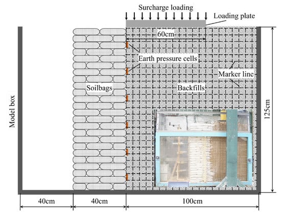
Figure 1.
Schematic diagram of soilbag-reinforced retaining wall.

Table 1.
Main performance parameters of woven bags.
For the evaluation of the model testing wall’s response to surcharge loads, six small earth pressure cells, each measuring 2 cm in diameter and 0.5 cm in height, were strategically embedded in the sand during its placement, as depicted in Figure 1. These cells, capable of measuring pressures in the range of 0–50 kPa with a precision of up to 0.1 kPa, were essential for accurate data collection. To facilitate the observation of backfill movement, a series of black marker lines were applied to the external surface of the glass, complemented by an equal number of white cotton lines aligned internally in identical positions. These internal lines were designed to shift corresponding to the movement of the backfill, whereas the external marker lines were intended to remain fixed. This arrangement allowed for the determination of backfill movement through the comparison of the relative positions of these marker lines, both inside and outside the glass. To systematically monitor these movements, a camera was strategically positioned in front of the model setup, enabling the continuous tracking of line movement at predetermined intervals.
2.2. Test Result
In the conducted model test, the retaining wall experienced failure when the surcharge stress escalated to 8.7 kPa. Figure 2 and Figure 3 depict the deformation of white cotton lines at surcharge stresses of 4 kPa and 8.7 kPa, respectively. It was observed that at a surcharge stress of 4 kPa, the backfill exhibited movement toward the soilbag-reinforced retaining wall, as indicated by the displacement of the white cotton lines relative to the black marking lines. This movement was attributed to the compression deformation of the soilbag under the surcharge stress. Upon reaching a surcharge stress of 8.7 kPa, a distinctive stepped sliding surface emerged within the structure of the soilbag-reinforced retaining wall, signaling its failure, as evidenced in Figure 3. Fan et al. [10] claimed that the ladder-like sliding surface formation is attributed to the interlayer insertion of soilbags. When the wall failed, a sliding surface emerged in the backfill behind the wall, which aligned nearly in a straight line. This sliding surface formed an angle of 60° with the horizontal plane, closely resembling the theoretical angle of 45 degrees plus half the internal friction angle (φ/2), as illustrated in Figure 3b. The upper portion of this stepped sliding surface exhibited horizontal movement. The critical height of the sliding wall (Hcrit) in this scenario was measured at 0.95 m.
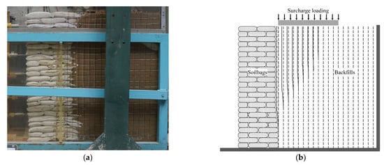
Figure 2.
Deformation of the backfill in the wall subjected to surcharge stress of 4 kPa (a) photo; (b) schematic diagram.
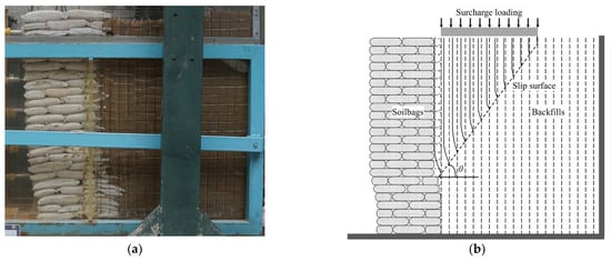
Figure 3.
Deformation of the backfill in the wall subjected to surcharge stress of 8.7 kPa (a) photo; (b) schematic diagram.
This present research focuses on assessing the earth pressure on walls subjected to surcharge loads under non-limited conditions. Therefore, the lateral earth pressure acting on the wall at different stages of surcharge stress, specifically at 2 kPa, 4 kPa, 6 kPa, and 8 kPa, were measured. The results are shown in Figure 4. Notably, during these stages, the retaining wall remains undamaged. The distribution of lateral earth pressure on the wall is characterized as non-linear. As the surcharge stress increases, there is a corresponding increase in the lateral earth pressure exerted on the wall. The static and active earth pressures of the wall at the surcharge stress of 4 kPa were calculated using Coulomb’s earth pressure theory, as illustrated in Figure 4. The earth pressures acting on the wall were found to be within the range of the static and active earth pressures, confirming the non-limited state of the earth pressure.

Figure 4.
Distribution of lateral earth pressures on soilbag-reinforced retaining walls subjected to surcharge loads under non-limited states.
3. Analytical Approaches
The assessment of earth pressure is a crucial component in studies focusing on retaining structures, as it significantly influences both the stability and the cost of retaining walls. Within this realm, the Rankine and Coulomb earth pressure theories are recognized as foundational approaches for estimating earth pressure. However, a limitation shared by these theories is their assumption of soil remaining static, disregarding any wall displacement. Through comprehensive model experiments, the active earth pressure displays a nonlinear pattern when retaining walls experience either translation or rotation, thereby rendering traditional earth pressure theories inadequate [23]. Consequently, numerous academics have developed alternative approaches for calculating earth pressure under varying displacement scenarios of retaining walls. Widely adopted methods include the differential element method [24,25,26] and the finite element numerical method [27,28,29]. The differential element method, specifically, is formulated based on conditions involving a retaining wall with a vertical back, sandy soil fill, and a horizontal surface behind the wall. This method segments the sliding wedge behind the wall into horizontal soil elements, presuming a uniform vertical stress distribution across these elements. Subsequently, the earth pressure calculation solution is derived by considering both the static and moment equilibrium of the soil elements, revealing a nonlinear soil pressure distribution. This method has been effectively applied in calculating active earth pressure for various types of retaining walls, yielding favorable results [30,31,32].
Originally, the differential element method was utilized predominantly for calculating the active earth pressure of retaining walls in a limited state. To extend its application to non-limited states, several scholars have refined this approach. Notably, Tang and Chen [33] contributed by developing theoretical formulations linking wall displacement to the friction angle in non-limited states. Subsequent methodologies introduced by other researchers have largely followed the foundational principles set by Tang and Chen, with variations in computing the effective friction angle under non-limited state scenarios [34].
In the conducted model test, it was observed that the active earth pressure exerted on the soilbag-reinforced retaining wall under non-limited conditions displayed a nonlinear behavior. Furthermore, the conditions under which the wall operated were consistent with the prerequisites for applying the differential element method. As a result, this method was effectively employed to compute the non-linear earth pressures that were recorded in the test.
3.1. Basic Equation for Non-Limited Active Earth Pressure
In the context of analyzing a sliding wedge as an isolated entity, as depicted in Figure 5a, a differential flat element with a thickness of dz is selected from the wedge, positioned at a depth of z beneath the backfill surface. In conditions where surcharge stress is absent (q = 0), the pressure exerted by the backfill due to filling is characterized as static earth pressure. Conversely, when surcharge stress, which does not compromise the integrity of the retaining wall (q = qint), is applied to the backfill, the soil’s immediate response is hindered, leading to a swift increase in lateral earth pressure, as demonstrated in Figure 5b. This escalation in lateral earth pressure consequently prompts compression in the neighboring soilbag, resulting in augmented compression deformation of the soilbag. Concurrently, there is an observable increase in the swelling deformation along with a decrease in the backfill’s lateral earth pressure. Equilibrium is attained once the lateral earth pressure equilibrates with the lateral compressive stress applied to the soilbag. At this juncture, the lateral swelling deformation of the backfill matches the lateral compressive deformation of the soilbag, as shown in Figure 5b. The relationship established upon achieving equilibrium following the application of surcharge stress qint is as follows:
where px−bf and εx−bf are the lateral earth pressure and strain of the backfill, σx−sb and εx−sb are the lateral compressed stress and strain of soilbag, Bbf is the width of the differential flat element, and Bsb is the width of the soilbagreinforced retaining wall.
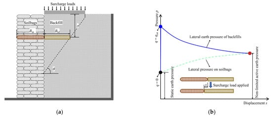
Figure 5.
Analytical model: (a) differential flat element of backfill in sliding wedge; (b) variations of lateral earth pressure caused by backfill and lateral pressure on soilbags.
Building upon the findings of Wang [35], the lateral earth pressure exerted by the backfill can be expressed as:
where Kq and Kγ are the surcharge pressure coefficient and the backfill pressure coefficient, respectively. These coefficients are inherently linked to the strain experienced by the differential flat element.
The lateral compressed stress of soilbags can be expressed as:
where Ex−sb is the elastic modulus of the soilbag, and K0 is the static earth pressure coefficient of the backfill.
By solving simultaneous Equations (1)–(3), the non-limited active earth pressure exerted on soilbag-reinforced retaining walls subjected to surcharge loads can be determined.
3.2. Determination of Kq and Kγ
In limited-state scenarios, retaining walls exhibit complete sliding wedges, where the backfill’s internal friction angle (φcirt) and the friction angle at the backfill-wall interface (δcrit) peak. In contrast, non-limited states yield only partial wedge development, resulting in lower, or intermediate, friction angles (φint for backfill internal friction and δint for backfill-wall friction). These intermediate values, lower than φcirt and δcrit, indicate a less intense stress condition. Fan et al. [36] outline a procedure to calculate φint and δint, suggesting these angles lie between their initial (φ0 and δ0, representing the starting internal and interface friction angles) and critical states. This approach helps in precisely gauging the frictional behavior of retaining walls under varying conditions.
The calculation equations provided by Fan et al. [36] for φint and δint are as follows:
where scrit is the critical lateral displacement necessary to reach the fully active state of the backfill. For walls with layered backfill, δ0 is proposed to be half of φcirt (i.e., δ0 = φcirt/2), and φ0 can be derived from Equation (6) [37]:
Sherif et al. [38] provided an empirical equation for scrit in retaining walls with varying densities of sand through model tests:
By solving Equations (4)–(7), the values of φint and δint can be determined.
From the equilibrium analysis of horizontal and vertical forces, as well as the moment equilibrium about the midpoint on the sliding surface of a differential flat element, a set of equations can be derived:
- 1.
- Equation (8) represents the balance of horizontal forces:
- 2.
- Equation (9) addresses the vertical force equilibrium, given by:
- 3.
- Equation (10) pertains to the moment equilibrium:
In these equations, θ is the sliding angle (θ = 45° + φ/2), qbf is the force on the top of the element, Rbf is the normal reaction of the backfill soil at rest, and dW is the weight of the element (dWbf = γ (Hcrit − z) cot θ dz).
Equations (8) and (10) can be simplified as:
Ignoring the second-order differential terms yields, Equation (9) can be expressed as:
Substituting Equation (12) into Equation (13) yields
Substituting Equation (14) into Equation (12) yields:
where N = 1/(cot δint cot (θ − φint) − 1).
By differentiation, the general solution of Equation (15) is
where C is a constant, which can be determined by the boundary condition (z = 0, qbf = q). C is determined as
Thus, Equation (16) can also be expressed as:
Substituting Equation (18) into Equation (14), px−bf can be obtained:
Solving for Equations (2) and (19) yields:
3.3. Determination of Ex−sb
The lateral compressive stress–strain characteristics of soilbags were investigated using a direct shear test apparatus, details of which are elaborated in the work of Fan et al. [5]. In this setup, two layers of soilbags were positioned on the apparatus’s base. The lower layer was anchored using two plates fixed to the base, ensuring stability during testing. Above the soilbags, a loading plate was placed, accompanied by a right-side plate. This arrangement was designed to apply normal stresses to the soilbags. A critical component of the setup was a displacement sensor attached to the right-side plate. This sensor’s role was to precisely track any lateral displacement that occurred during the testing process. For the application of lateral force, a controlled speed of 1 mm/min was maintained, and a load cell was incorporated to measure the lateral force exerted.
The results of these tests are depicted in Figure 6, which illustrates the lateral compressive stress–strain relationship of the soilbags under varying normal stresses. The data indicate a roughly linear relationship between lateral stress and strain across different levels of normal stress. This linear trend suggests a consistent response of the soilbags to lateral compression. Figure 7 presents the correlation between the lateral compressive modulus (Ex−sb) and the normal stress (σz−sb) of the soilbag. This relationship reveals that the Ex−sb value progressively increases as σz−sb increases, demonstrating a distinct exponential connection between these two parameters. This observed relationship can be quantitatively described by an exponential function, where the lateral stress–strain relationship of the soilbag is modeled as:
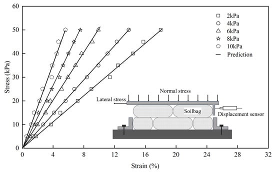
Figure 6.
Lateral stress–strain relationship of soilbags at different normal stresses.
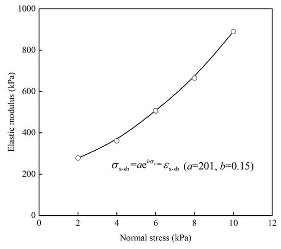
Figure 7.
Relationship between elastic modulus and normal stresses of soilbags.
Further simplification leads to the expression for the lateral compressive modulus (Ex−sb) as:
where a = 201 and b = 0.15.
3.4. Validation
In the described model test, key parameters include the unit weight of the backfill (γ) at 17.6 kN/m3, the internal friction angle (φcrit) at 35.4°, the frictional angle between the back of the soilbag and the backfill (δcrit) at 28.1°, the width of the soilbag-reinforced retaining wall (Bsb) at 0.4 m, and the critical height of the wall (Hcrit) at 0.95 m. Utilizing the previously mentioned equations, the lateral displacement and lateral earth pressures of the backfill along the wall height were calculated under varying surcharge loads of 2 kPa, 4 kPa, 6 kPa, and 8 kPa.
The findings revealed that under a 2 kPa surcharge stress, the calculated lateral displacement along the wall height remained below the critical lateral displacement (scrit). This suggests that, in this scenario, the wall did not reach its limit state, as depicted in Figure 8a. However, as the surcharge load increased to 4 kPa, a notable change was observed. The lateral displacement of the soilbag at the upper part of the wall exceeded scrit, indicating that this portion of the wall had reached the limit state, as shown in Figure 8b. Furthermore, the extent of the wall reaching the limit state increased progressively with the increment of the surcharge loads, as shown in Figure 8c,d. Another key observation from Figure 8a–d is the close agreement between the calculated earth pressure and the experimental data. This alignment validates the accuracy of the calculations and the effectiveness of the equations used in predicting the behavior of the soilbag and the retaining wall under different loading conditions.
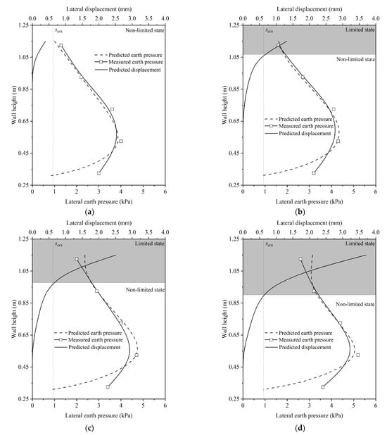
Figure 8.
Distribution of non-limited lateral earth pressures under different surcharge loads of (a) 2 kPa, (b) 4 kPa, (c) 6 kPa, and (d) 8 kPa.
3.5. Influencing Factors Analysis
The effect of soilbag-related parameters, namely the compression modulus of the soilbag (Ex−sb) and the width of the soilbag-reinforced retaining wall (Bsb), on the distributions of lateral displacement and earth pressure along the wall height at a surcharge stress of 4 kPa, was investigated using the proposed method. Equation (23) reveals a positive correlation between the compression modulus of the soilbag and parameters a and b. By varying the values of a and b, the impact of Ex−sb on earth pressure and deformation was explored, as illustrated in Figure 9. An increase in Ex−sb was observed to reduce the lateral displacement caused by the soilbag. This reduction in lateral displacement of the backfill led to an increase in earth pressure. The effect of varying Bsb on earth pressure and deformation is presented in Figure 10. Theoretically, augmenting the wall’s thickness is posited to enhance its stability. However, under a specific surcharge load, the earth pressure is observed to decrease with an increase in wall thickness, while lateral displacement exhibits an increase with wall thickening.
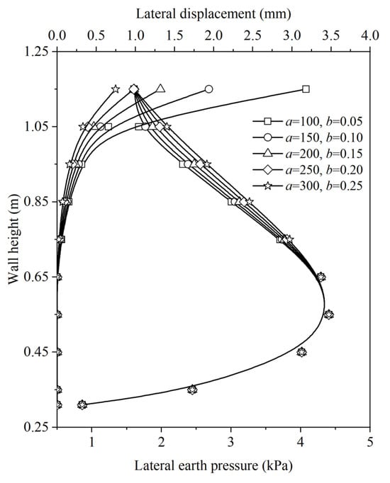
Figure 9.
Effect of Ex−sb on distributions of lateral displacement and earth pressure along the wall height.
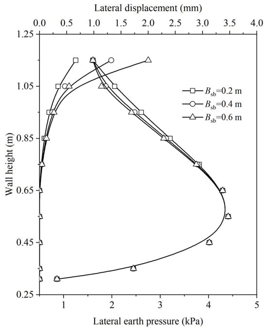
Figure 10.
Effect of Bsb on distributions of lateral displacement and earth pressure along the wall height.
4. Conclusions
Model tests on the soilbag-reinforced retaining wall subjected to surcharge loads under the non-limited state were carried out to analyze the non-limited earth pressures. The findings yielded several key insights:
- The lateral earth pressure distribution on the soilbag-reinforced retaining wall subjected to surcharge loads under the non-limited state is non-linear. As the surcharge loads increased, there was a corresponding increase in the earth pressure.
- It was determined through experimentation that the lateral stress–strain behavior of the soilbags adheres to a linear model. Furthermore, an exponential relationship between the lateral compression modulus of the soilbags and the normal stress was established.
- The analytical solution, developed based on the force equilibrium of differential elements, proved to be highly effective in predicting the non-limited lateral earth pressure on the soilbag-reinforced retaining wall under surcharge loads. The effect of the compression modulus of the soilbag and the width of the soilbag-reinforced retaining wall on the non-limited earth pressure was examined using the analytical solution. It is shown that the earth pressure increases with the increasing compression modulus of the soilbag and the decreasing width of the wall.
Although the calculated earth pressure aligns well with the experimental data, aspects such as arching effects and their influence on earth pressure, which have been acknowledged to affect earth pressure in previous studies, were not investigated in this research. Additionally, the scope of our experimental setup and the scale of the model tests may limit the direct applicability of our findings to real-world scenarios without further validation. It is advised that readers consider these limitations while interpreting the findings.
Author Contributions
Conceptualization, C.B. and K.F.; methodology, R.L. and Z.L.; validation, C.B., Z.W. and K.F.; formal analysis, R.L.; investigation, C.B.; resources, Z.L. and K.F.; data curation, C.B.; writing—original draft preparation, C.B.; writing—review and editing, R.L. and Z.L.; visualization, C.B. and R.L.; supervision, Z.L., Z.W. and K.F.; project administration, Z.L. and Z.W.; funding acquisition, Z.L. and Z.W. All authors have read and agreed to the published version of the manuscript.
Funding
This research was funded by the National Key Research and Development Project (Grant number 2023YFC3206203), the Outstanding Youth and Excellent Youth Science Funds of Henan Province (Grant number 222300420013 and number 232300421065), Beijing Jianghe Water Development Foundation, Young Talents of Water Conservancy Science and Technology Fund support (Grant number YC202306), the Promotion and Transformation Fund of the Yellow River Institute of Hydraulic Research (Grant number HKY-YF-2022-03), and the Central Public-interest Scientific Institution Basic Research Fund (Grant number HKY-JBYW-2021-01).
Institutional Review Board Statement
Not applicable.
Informed Consent Statement
Not applicable.
Data Availability Statement
The data presented in this study may be available on reasonable request from the first or corresponding author.
Conflicts of Interest
The authors declare no conflicts of interest.
References
- Palmeira, E.M.; Araújo, G.L.S.; Santos, E.C.G. Sustainable solutions with geosynthetics and alternative construction materials—A review. Sustainability 2021, 13, 12756. [Google Scholar] [CrossRef]
- Rimoldi, P.; Shamrock, J.; Kawalec, J.; Touze, N. Sustainable use of geosynthetics in dykes. Sustainability 2021, 13, 4445. [Google Scholar] [CrossRef]
- Fan, K.W.; Pei, Q.; Liu, L.; Han, Z.; Zou, W.L. Strength and microstructure of a lignin fiber-reinforced expansive soil in cold regions. Geosyn. Int. 2022, 29, 622–629. [Google Scholar] [CrossRef]
- Prambauer, M.; Wendeler, C.; Weitzenböck, J.; Burgstaller, C. Biodegradable geotextiles–An overview of existing and potential materials. Geotext. Geomembr. 2019, 47, 48–59. [Google Scholar] [CrossRef]
- Chmura, D.; Salachna, A.; Broda, J.; Kobiela-Mendrek, K.; Gawłowski, A.; Rom, M. Multifunctional Geotextiles Produced from Reclaimed Fibres and Their Role in Ecological Engineering. Materials 2022, 15, 7957. [Google Scholar] [CrossRef] [PubMed]
- Fan, K.W.; Zou, W.L.; Zhang, P.; Wang, X.Q.; Shen, Y. Laboratory investigation and theoretical analysis of lateral pressure exerted by expansive soils on retaining walls with expanded polystyrene geofoam block upon water infiltration. Geotext. Geomembr. 2023, in press. [Google Scholar] [CrossRef]
- Kim, M.; Freeman, M.; Fitzpatrick, B.T.; Nevius, D.B.; Plaut, R.H.; Filz, G.M. Use of an apron to stabilize geomembrane tubes for fighting floods. Geotex. Geomembr. 2004, 22, 239–254. [Google Scholar] [CrossRef]
- Matsuoka, H.; Liu, S.H. New earth reinforcement method by soilbags (‘Donow’). Soils Found. 2003, 43, 173–188. [Google Scholar] [CrossRef]
- Doi, T.; Murono, Y.; Zhang, F.; Hirayama, Y. In-situ horizontal cyclic loading tests on composite foundation composed of soilbags and piles. Soils Found. 2023, 63, 101327. [Google Scholar] [CrossRef]
- Fan, K.W.; Liu, S.H.; Cheng, Y.P.; Wang, Y.S. Sliding stability analysis of a retaining wall constructed by soilbags. Géotechnique Lett. 2019, 9, 211–217. [Google Scholar] [CrossRef]
- Lohani, T.N.; Matsushima, K.; Aqil, U.; Mohri, Y.; Tatsuoka, F. Evaluating the strength and deformation characteristics of a soil bag pile from full-scale laboratory tests. Geosyn. Int. 2006, 13, 246–264. [Google Scholar] [CrossRef]
- Liu, S.H.; Fan, K.W.; Xu, S.Y. Field study of a retaining wall constructed with clay-filled soilbags. Geotext. Geomembr. 2019, 47, 87–94. [Google Scholar] [CrossRef]
- Wang, Y.Q.; Liu, K.; Li, X.; Ren, Q.B.; Li, L.L.; Zhang, Z.H.; Li, M.C. Experimental and upper-bound study of the influence of soilbag tail length on the reinforcement effect in soil slopes. Geotext. Geomembr. 2019, 47, 610–617. [Google Scholar] [CrossRef]
- Matsushima, K.; Aqil, U.; Mohri, Y.; Tatsuoka, F.J.G.I. Shear strength and deformation characteristics of geosynthetic soil bags stacked horizontal and inclined. Geosyn. Int. 2008, 15, 119–135. [Google Scholar] [CrossRef]
- Liu, S.; Jia, F.; Shen, C.; Weng, L.P. Strength characteristics of soilbags under inclined loads. Geotext. Geomembr. 2018, 46, 1–10. [Google Scholar] [CrossRef]
- Kim, J.S.; Barker, R.M. Effect of live load surcharge on retaining walls and abutments. J. Geotech. Geoenviron. Eng. 2002, 128, 803–813. [Google Scholar] [CrossRef]
- Yoo, C.; Kim, S.B. Performance of a two-tier geosynthetic reinforced segmental retaining wall under a surcharge load: Full-scale load test and 3D finite element analysis. Geotext. Geomembr. 2008, 26, 460–472. [Google Scholar] [CrossRef]
- Dave, T.; Dasaka, S. Transition of earth pressure on rigid retaining walls subjected to surcharge loading. Int. J. Geotech. Eng. 2012, 6, 427–436. [Google Scholar] [CrossRef]
- Ghanbari, A.; Taheri, M. An analytical method for calculating active earth pressure in reinforced retaining walls subject to a line surcharge. Geotext. Geomembr. 2012, 34, 1–10. [Google Scholar] [CrossRef]
- Srikar, G.; Mittal, S. Seismic analysis of retaining wall subjected to surcharge: A modified pseudodynamic approach. Int. J. Geomech. 2020, 20, 06020022. [Google Scholar] [CrossRef]
- O’Neal, T.S.; Hagerty, D.J. Earth pressures in confined cohesionless backfill against tall rigid walls—A case history. Can. Geotech. J. 2011, 48, 1188–1197. [Google Scholar] [CrossRef]
- ’Zhang, J.; Shamoto, Y.; Tokimatsu, K. Evaluation of earth pressure under any lateral deformation. Soils Found 1998, 38, 15–33. [Google Scholar] [CrossRef]
- Fang, Y.S.; Ishibashi, I.; Lee, C.D. Static earth pressure with various wall movements. J. Geotech. Eng. 1986, 112, 317–333. [Google Scholar] [CrossRef]
- Paik, K.H.; Salgado, R. Estimation of active earth pressure against rigid retaining walls considering arching effects. Géotechnique 2003, 53, 643–653 ttps://doiorg/101680/geot2003537643. [Google Scholar] [CrossRef]
- Khosravi, M.H.; Pipatpongsa, T.; Takemura, J. Experimental analysis of earth pressure against rigid retaining walls under translation mode. Géotechnique 2013, 63, 1020–1028. [Google Scholar] [CrossRef]
- Rao, P.; Chen, Q.; Zhou, Y.; Nimbalkar, S.; Chiaro, G. Determination of active earth pressure on rigid retaining wall considering arching effect in cohesive backfill soil. Int. J. Geomech. 2016, 16, 04015082. [Google Scholar] [CrossRef]
- Tran, V.D.; Meguid, M.A.; Chouinard, L.E. Discrete element and experimental investigations of the earth pressure distribution on cylindrical shafts. Int. J. Geomech. 2014, 14, 80–91. [Google Scholar] [CrossRef]
- Fathipour, H.; Siahmazgi, A.S.; Payan, M.; Chenari, R.J. Evaluation of the lateral earth pressure in unsaturated soils with finite element limit analysis using second-order cone programming. Comput. Geotech. 2020, 125, 103587. [Google Scholar] [CrossRef]
- Tyrer, J.; Paraskevopoulou, C.; Shah, R.; Miller, R.; Kavvadas, M. Tunnelling with Full-Face Shielded Machines: A 3D Numerical Analysis of an Earth Pressure Balance (EPB) Excavation Sequence Using the Finite Element Method (FEM). Geosciences 2023, 13, 244. [Google Scholar] [CrossRef]
- Patel, S.; Deb, K. Study of active earth pressure behind a vertical retaining wall subjected to rotation about the base. Int. J. Geomech. 2020, 20, 04020028. [Google Scholar] [CrossRef]
- Khosravi, M.H.; Pipatpongsa, T.; Takemura, J. Theoretical analysis of earth pressure against rigid retaining walls under translation mode. Soils Found. 2016, 56, 664–675. [Google Scholar] [CrossRef]
- Kim, K.Y.; Lee, D.S.; Cho, J.; Jeong, S.S.; Lee, S. The effect of arching pressure on a vertical circular shaft. Tunn. Undergr. Space Techn. 2013, 37, 10–21. [Google Scholar] [CrossRef]
- Tang, Y.; Chen, J.G. Calculation of Active Earth Pressure in the Non-Limit State Based on Wedge Unit Method. Soil Mech. Found. Eng. 2020, 56, 390–397. [Google Scholar] [CrossRef]
- Wang, L.; Xiao, S.G. Calculation method for displacement-dependent earth pressure on a rigid wall rotating around its base. Int. J. Geomech. 2021, 21, 04021132. [Google Scholar] [CrossRef]
- Wang, Y.Z. Distribution of earth pressure on a retaining wall. Géotechnique 2000, 50, 83–88. [Google Scholar] [CrossRef]
- Fan, K.W.; Yang, G.Q.; Zou, W.L.; Han, Z.; Shen, Y. Lateral Earth Pressure of Granular Backfills on Retaining Walls with EPS Geofoam Inclusions under Limited Surcharge Loading: Experimental Studies and Analytical Approaches. J. Rock Mech. Geotech. Eng. 2023, in press. [Google Scholar] [CrossRef]
- Chang, M.F. Lateral earth pressures behind rotating walls. Can. Geotech. J. 1997, 34, 498–509. [Google Scholar] [CrossRef]
- Sherif, M.A.; Ishibashi, I.; Lee, C.D. Earth pressures against rigid retaining walls. J. Geotech. Eng. Div. 1982, 108, 679–695. [Google Scholar] [CrossRef]
Disclaimer/Publisher’s Note: The statements, opinions and data contained in all publications are solely those of the individual author(s) and contributor(s) and not of MDPI and/or the editor(s). MDPI and/or the editor(s) disclaim responsibility for any injury to people or property resulting from any ideas, methods, instructions or products referred to in the content. |
© 2024 by the authors. Licensee MDPI, Basel, Switzerland. This article is an open access article distributed under the terms and conditions of the Creative Commons Attribution (CC BY) license (https://creativecommons.org/licenses/by/4.0/).