
An Improved Grain Growth Model and Its Application in Gradient Heat Treatment of Aero-Engine Turbine Discs


Abstract
:1. Introduction
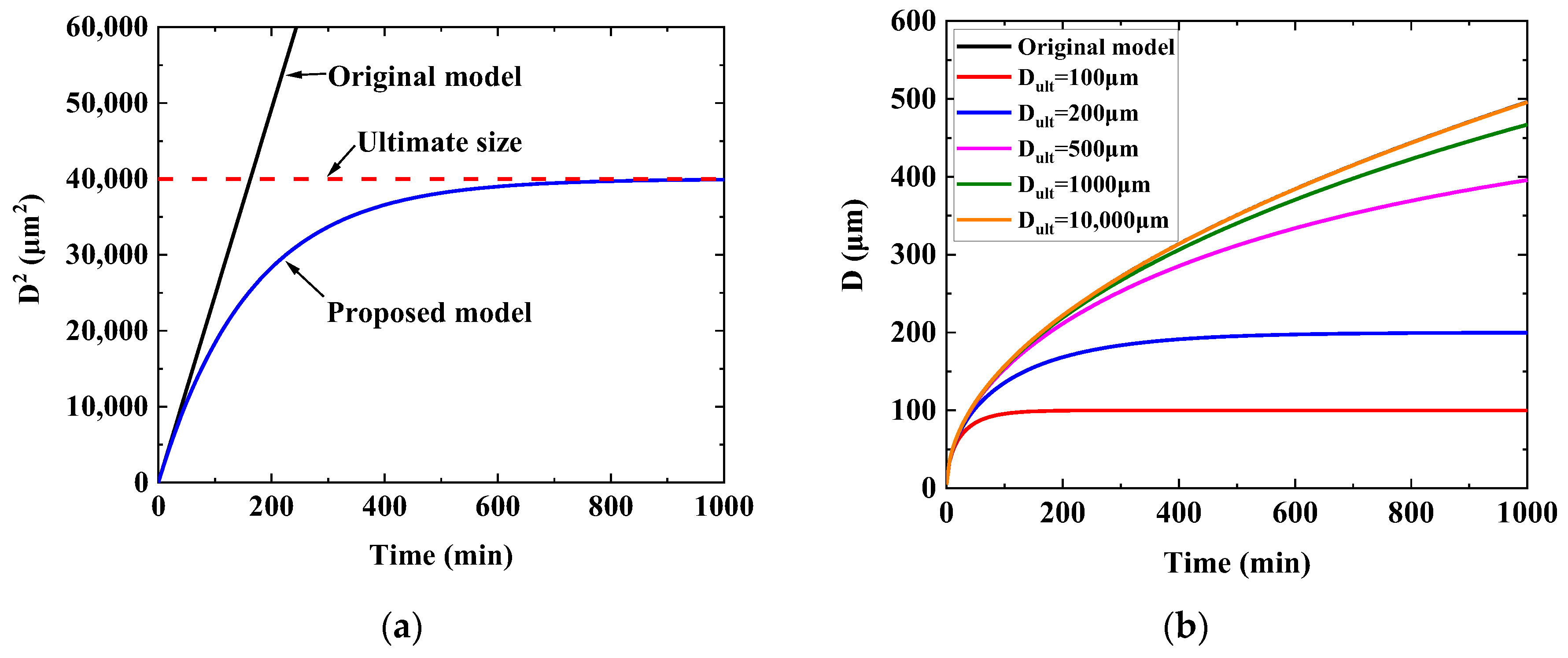
2. Grain Growth Model Development
3. Experimental Materials and Methods
4. Experimental Results and Model Parameter Determination
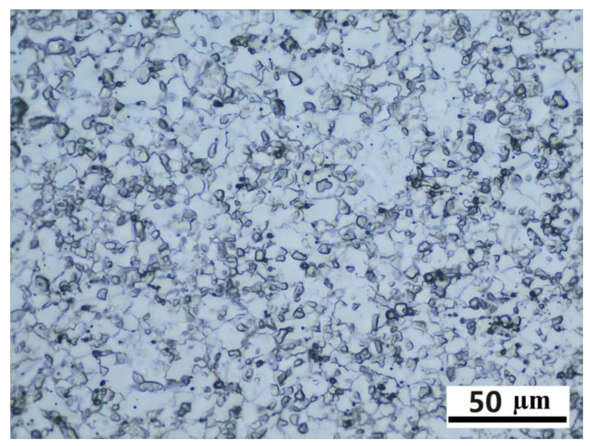
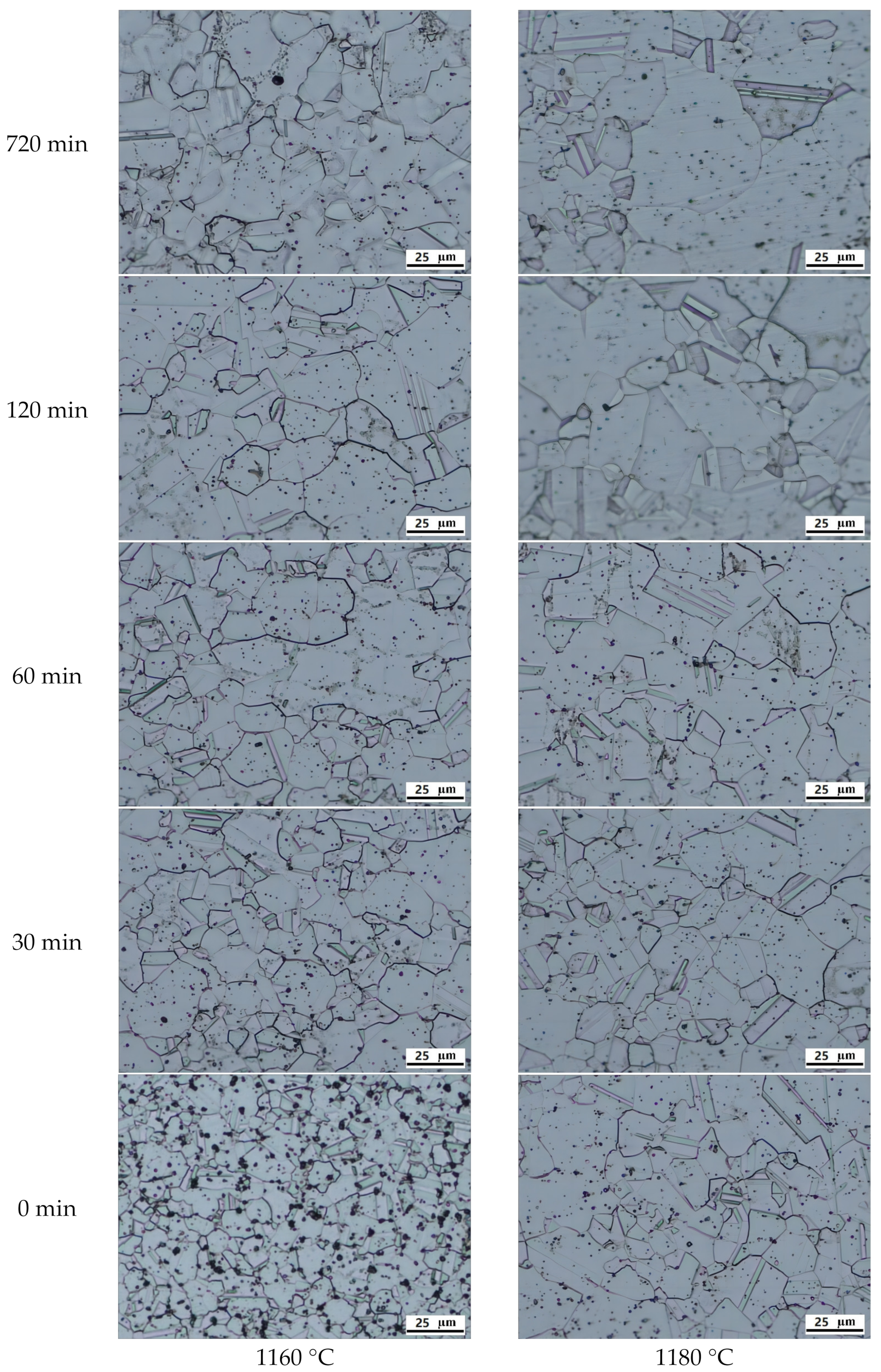
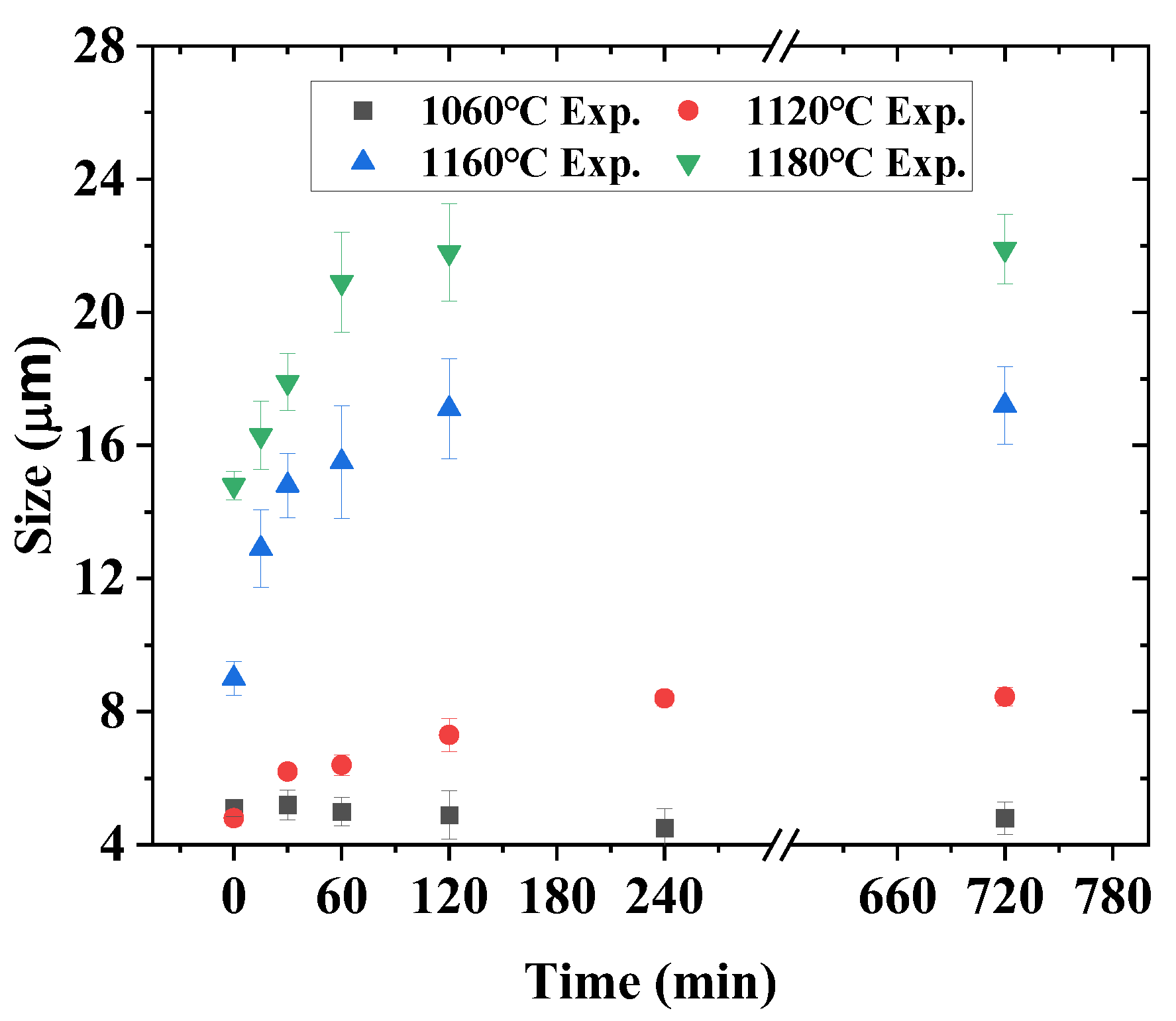
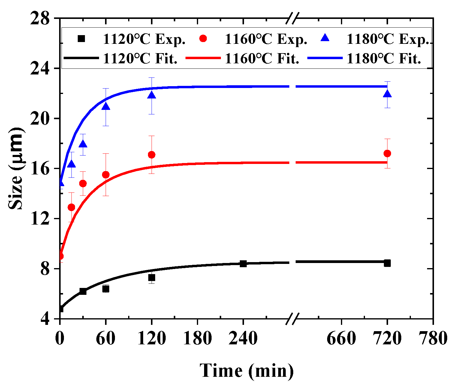
4.1. Experimental Results
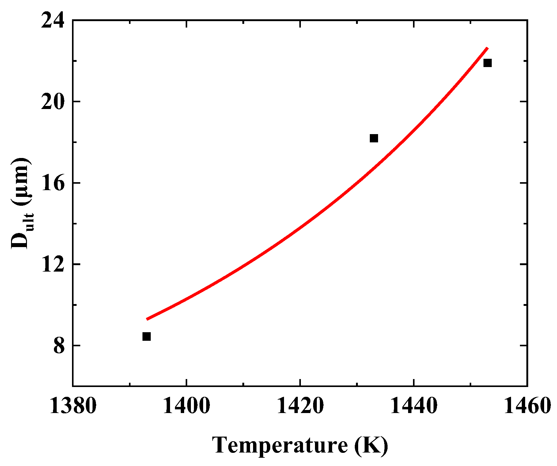
4.2. Parameter Calibration of Grain Growth Model
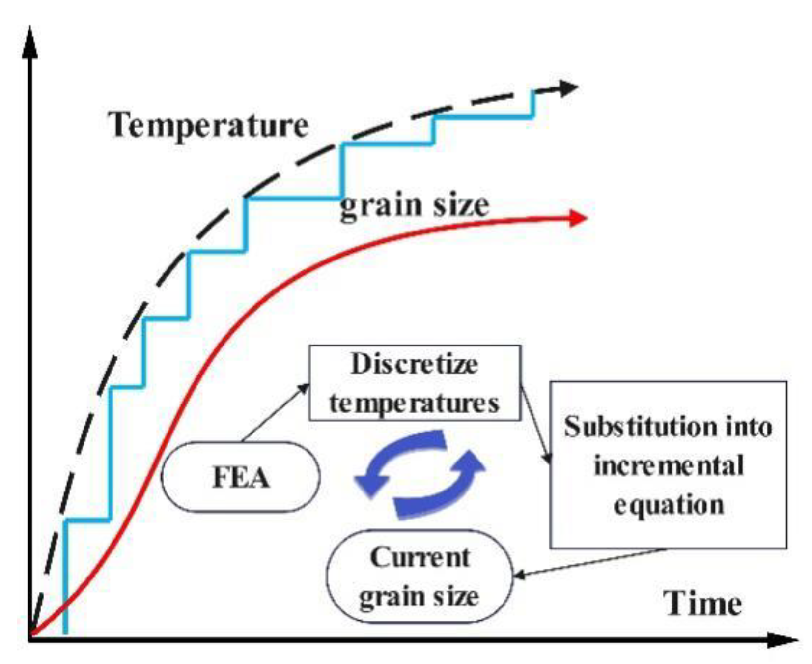
4.3. Grain Size Calculation Scheme
5. Grain Size Prediction of a Dual Microstructure Turbine Disk and Its Validation
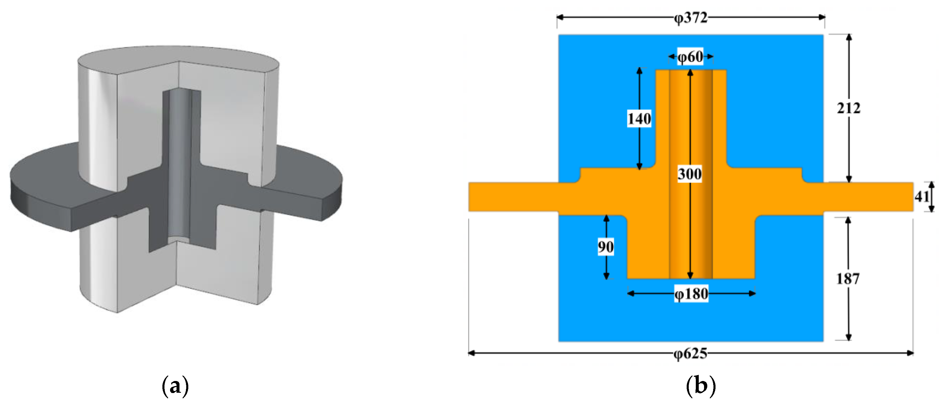
5.1. Gradient Heat Treatment Setup Design
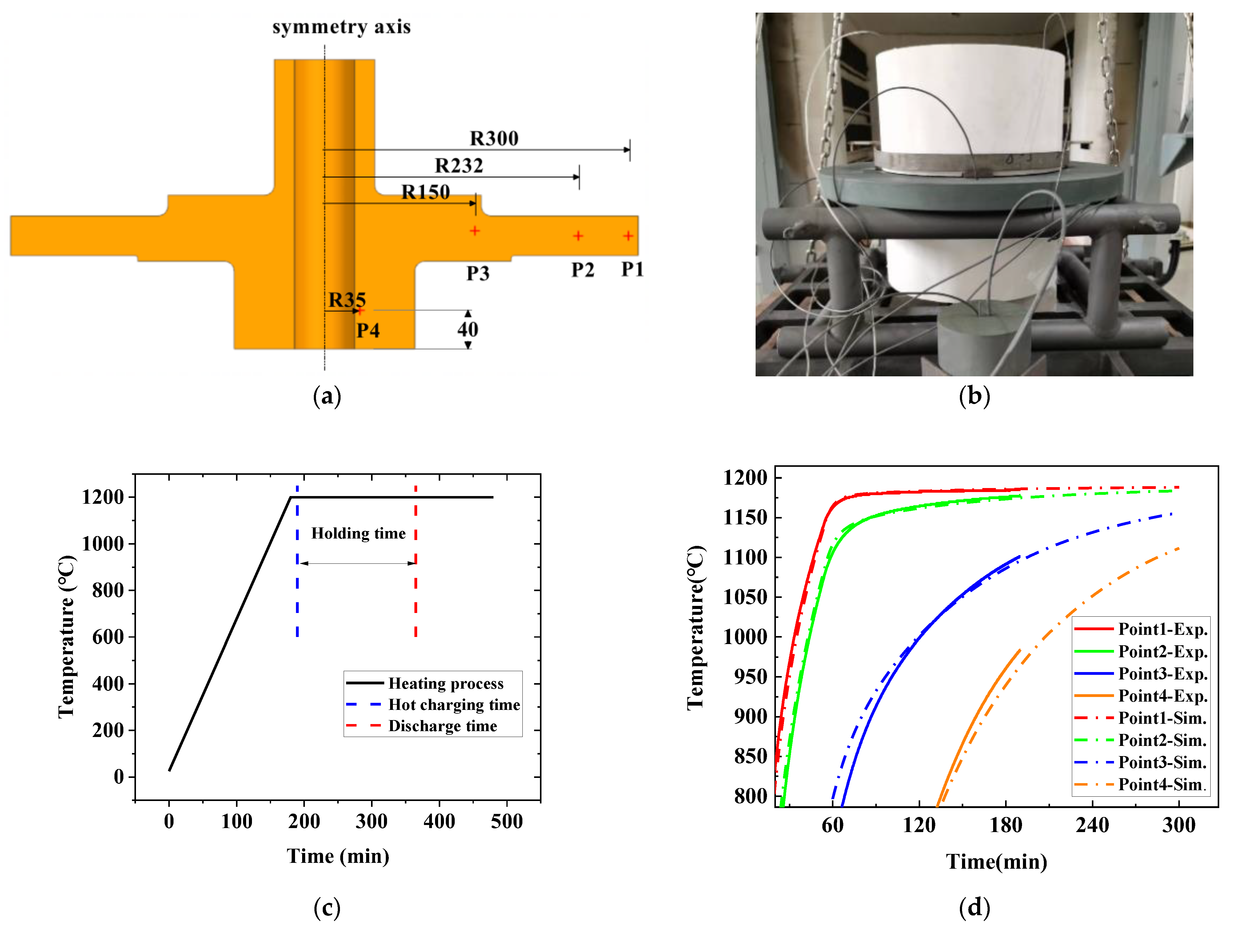
5.2. Heating Process of Gradient Heat Treatment
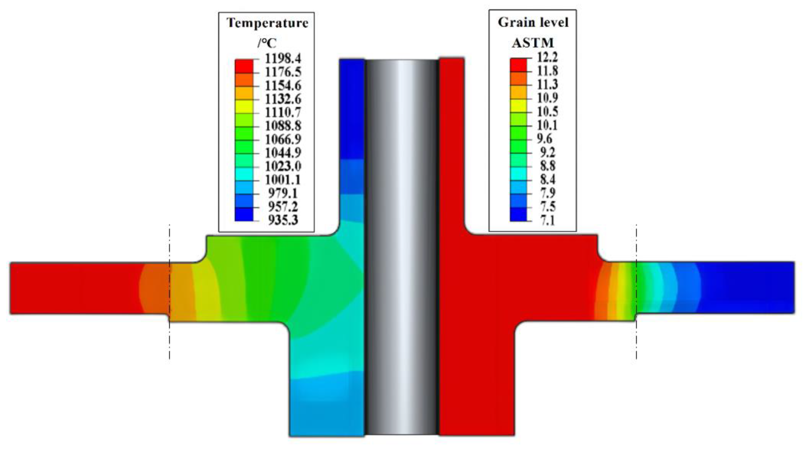
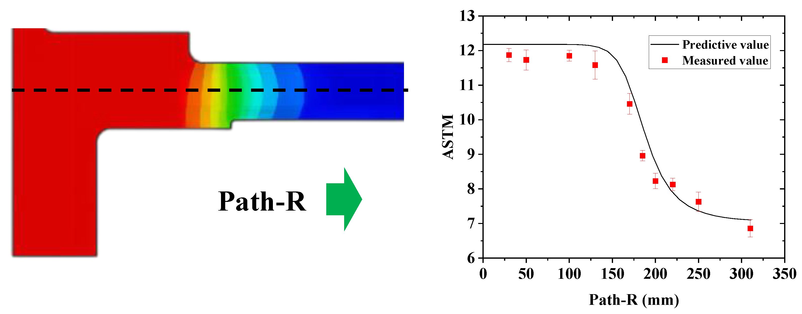
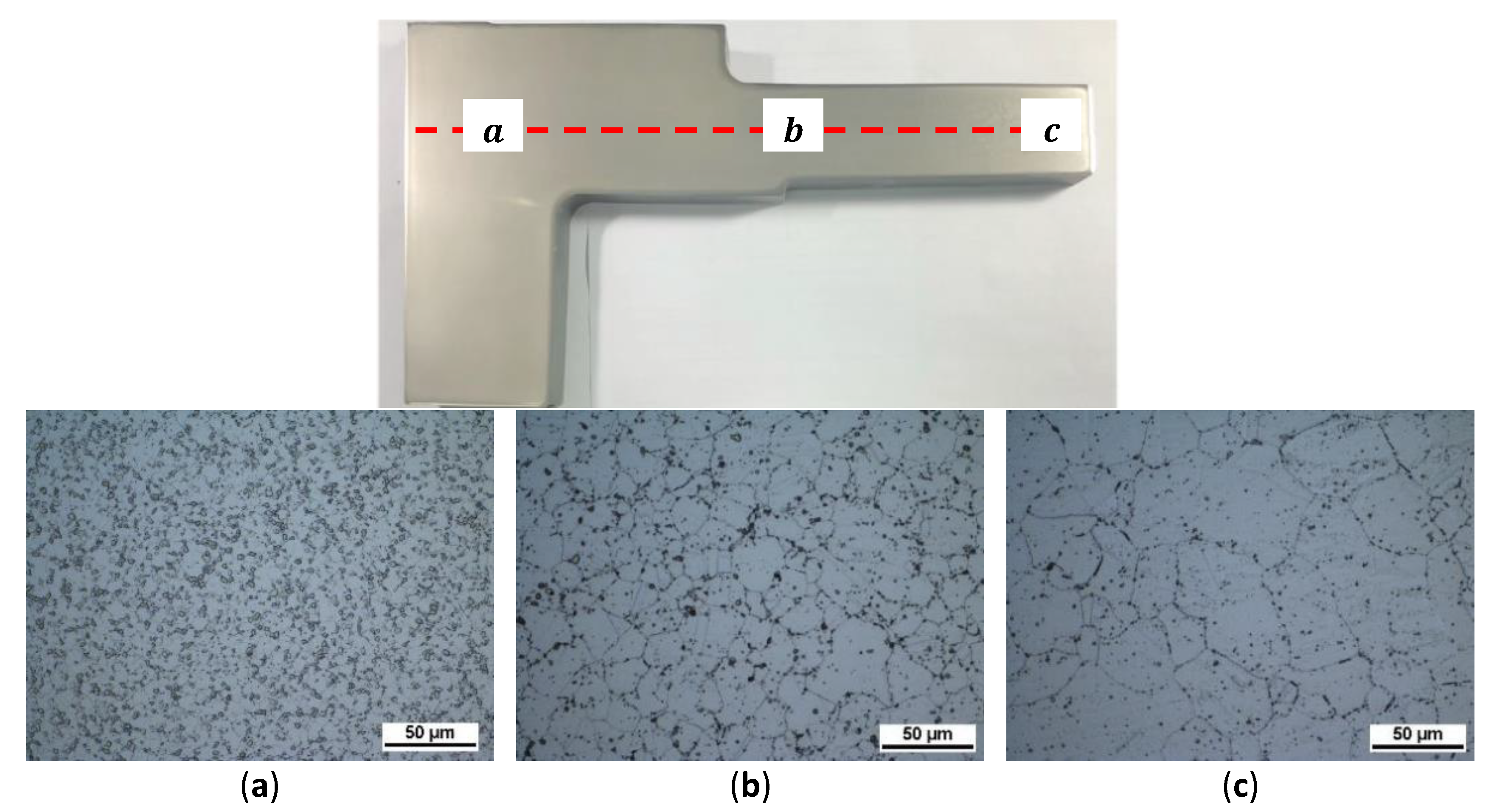
5.3. Prediction Validation
6. Conclusions
- (1)
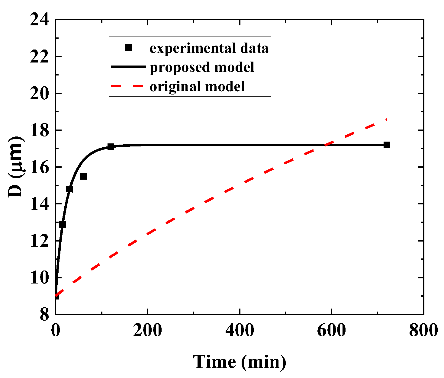
- A new grain growth model has been developed by combining the traditional model and the Zener pinning effect. This model can reflect how the ultimate grain size influences grain growth.
- (2)
- A simplified temperature-dependent ultimate grain size model has been proposed. It can be applied flexibly to materials exhibiting both single and multiple pinning mechanisms.
- (3)
- Isothermal grain growth experiments were conducted to study the grain growth of a nickel-based superalloy and to validate the proposed model.
- (4)
- The proposed grain growth model with a saturated grain size term can better predict grain growth. The model parameters were calibrated by experiments on small samples.
- (5)
- The proposed model was applied to a finite element analysis of the gradient heat treatment of a full-size turbine disc. The predicted grain size distribution matched the results of the metallographic examination very well. It demonstrates that the model can offer valuable guidance for optimizing subsequent processes to meet different requirements. This method can be extended to other alloys.
Author Contributions
Funding
Institutional Review Board Statement
Informed Consent Statement
Data Availability Statement
Acknowledgments
Conflicts of Interest
Abbreviations
| material parameters | |
| the generalized mobility constant | |
| the generalized mobility constant considering ultimate size | |
| material parameters | |
| Zenner pinning force constant | |
| grain size | |
| initial grain size | |
| the ultimate size | |
| the volume fraction | |
| temperature-dependent constant | |
| temperature-dependent constant considering ultimate size | |
| time-dependent exponent | |
| grain growth activation energy | |
| grain growth activation energy considering ultimate size | |
| radius of undissolved and coarsened particles | |
| gas constant | |
| annealing time | |
| annealing temperature | |
| solvus temperature of the pinning phase | |
| the grain boundary energy | |
| AA | argon atomization powder production |
| ASTM | grain size level |
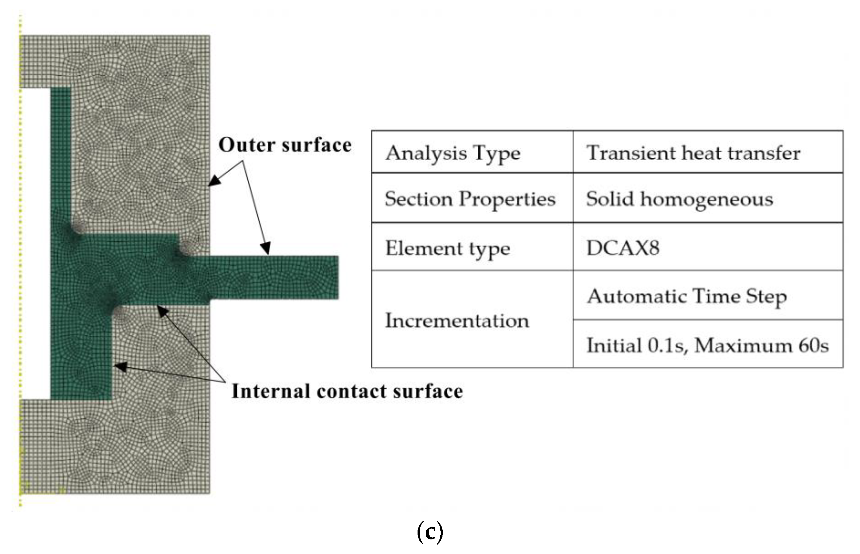
| FEM | finite element method |
| HIP | hot isostatic pressing |
| HEX | hot extrusion |
| IF | isothermal forging |
| VIM | vacuum induction melting |
| UVARM | user-defined state variables |
References
- Miodownik, M.A. A Review of Microstructural Computer Models Used to Simulate Grain Growth and Recrystallisation in Aluminium Alloys. J. Light Met. 2002, 2, 125–135. [Google Scholar] [CrossRef]
- Staublin, P.; Mukherjee, A.; Warren, J.A.; Voorhees, P.W. Phase-Field Model for Anisotropic Grain Growth. Acta Mater. 2022, 237, 118169. [Google Scholar] [CrossRef]
- Beck, P.A.; Kremer, J.C.; Demer, L.J. Grain Growth in High Purity Aluminum. Phys. Rev. 1947, 71, 555. [Google Scholar] [CrossRef]
- Burke, J.E.; Turnbull, D. Recrystallization and Grain Growth. Prog. Met. Phys. 1952, 3, 220–292. [Google Scholar] [CrossRef]
- Sellars, C.M.; Whiteman, J.A. Recrystallization and Grain Growth in Hot Rolling. Met. Sci. 1979, 13, 187–194. [Google Scholar] [CrossRef]
- Du, S.; Li, Y.; Zheng, Y. Kinetics of Austenite Grain Growth During Heating and Its Influence on Hot Deformation of LZ50 Steel. J. Mater. Eng. Perform. 2016, 25, 2661–2669. [Google Scholar] [CrossRef]
- Zhong, Y.; Liu, G.; Liu, S.; Liu, C.; Li, G.; He, Y.; Qian, H.; Li, H.; Jiang, Y. Austenite grain growth behavior of steel 33Mn2V designed for oil-well tubes. Acta Metall. Sin. 2003, 39, 5. (In Chinese) [Google Scholar]
- Tian, G.; Jia, C.; Liu, J.; Hu, B. Experimental and Simulation on the Grain Growth of P/M Nickel-Base Superalloy during the Heat Treatment Process. Mater. Des. 2009, 30, 433–439. [Google Scholar] [CrossRef]
- Andersen, I.; Grong, Ø. Analytical Modelling of Grain Growth in Metals and Alloys in the Presence of Growing and Dissolving Precipitates—I. Norm. Grain Growth. Acta Metall. Mater. 1995, 43, 2673–2688. [Google Scholar] [CrossRef]
- Yongtai, C.; Ming, X.; Youcai, Y.; Jiming, Z.; Manmen, L.; Saibei, W.; Yunfeng, Y. Effects of Zn Content on the Grain Growth Law of Ag-Cu-Zn Alloys. Rare Met. Mater. Eng. 2014, 43, 57–60. [Google Scholar] [CrossRef]
- Hu, H.; Rath, B.B. On the Time Exponent in Isothermal Grain Growth. Metall. Trans. 1970, 1, 3181–3184. [Google Scholar] [CrossRef]
- Lv, H.; Pan, Q.; Huang, Q.; Yu, X.; Lv, J.; Pan, G. Grain CoarseningBehavior of Inconel X-750 Superalloy. Spec. Cast. Nonferrous Alloys 2023, 43, 363–369. (In Chinese) [Google Scholar]
- Gladman, T. The Theory and Inhibition of Abnormal Grain Growth in Steels. JOM 1992, 44, 21–24. [Google Scholar] [CrossRef]
- Yang, G.; Sun, X.; Yong, Q.; Li, Z.; Li, X. Austenite Grain Refinement and Isothermal Growth Behavior in a Low Carbon Vanadium Microalloyed Steel. J. Iron Steel Res. Int. 2014, 21, 757–764. [Google Scholar] [CrossRef]
- Roy, I.; Balikci, E.; Ibekwe, S.; Raman, A. Precipitate Growth Activation Energy Requirements in the Duplex Size Γ′ Distribution in the Superalloy IN738LC. J. Mater. Sci. 2005, 40, 6207–6215. [Google Scholar] [CrossRef]
- Song, K.; Aindow, M. Grain Growth and Particle Pinning in a Model Ni-Based Superalloy. Mater. Sci. Eng. A 2008, 479, 365–372. [Google Scholar] [CrossRef]
- Cheng, J.; Xiong, J.; Liu, Z.; Zhu, L.; Guo, J. Sub-solvus Heat Treatment Study on the γ’ Distribution of Novel Nickel-Based. Rare Met. Mater. Eng. 2023, 52, 700–709. (In Chinese) [Google Scholar]
- Cheng, J.; Zhu, L.; Ma, X.; Xiao, L.; Ji, H.; Guo, J. Super-Solvus Heat Treatment Study of Novel Nickel-Based Superalloy. Rare Met. Mater. Eng. 2022, 51, 1–10. (In Chinese) [Google Scholar]
- Holm, E.; Foiles, S.M. How Grain Growth Stops: A Mechanism for Grain-Growth Stagnation in Pure Materials. Science 2010, 328, 1138–1141. [Google Scholar] [CrossRef]
- GB/T 6394-2017; Determination of Estimating the Average Grain Size of Metal. Standardization Administration of China: Beijing, China, 2017. (In Chinese)
- Hu, B.; Tian, G.; Jia, C.; Liu, G. Development in Double-Properties Turbine Disk of P/M Superalloy. J. Aeronaut. Mater. 2007, 27, 80–84. (In Chinese) [Google Scholar]
- Tao, Y.; Zhang, G.; Liu, J. Study on Design of the Device for Thermal Gradient Heat-Treatment Process of PM Superalloy Disks. J. Iron Steel Res. 2011, 23, 486–489. (In Chinese) [Google Scholar]
- Tian, G.; Jia, C.; Wu, K. Temperature Field Simulation for Dual-property P/M Superalloy Turbine Disk Subjected to Gradient Heat Treatment. China Steel Annu. Conf. 2007. (In Chinese). Available online: https://d.wanfangdata.com.cn/conference/6452369 (accessed on 14 September 2023).
- Miller, J.A.; Athey, R.L. Method of Producing Turbine Disks. 4608094. 26 August 1986. Available online: https://www.freepatentsonline.com/4608094.html (accessed on 14 September 2023).
- Walker, B.H. Process for Fabricating Multi-Alloy Components. 4529452. 16 July 1985. Available online: https://www.freepatentsonline.com/4529452.html (accessed on 14 September 2023).
- Chang, K. Method of Making High Strength Superalloy Components with Graded Properties. 4820358. 11 April 1989. Available online: https://www.freepatentsonline.com/4820358.html (accessed on 14 September 2023).
- Ganesh, S.; Tolbert, R.G. Differentially Heat Treated Article, and Apparatus and Process for the Manufacture Thereof. 5527020. 18 June 1996. Available online: https://www.freepatentsonline.com/5527020.html (accessed on 14 September 2023).
- Mathey, G.F. Method of Making Superalloy Turbine Disks Having Graded Coarse and Fine Grains. 5312497. 17 May 1994. Available online: https://www.freepatentsonline.com/5312497.html (accessed on 14 September 2023).
- Gayda, J.; Gabb, T.P.; Kantzos, P.T. Heat Treatment Devices and Method of Operation Thereof to Produce Dual Microstructure Superalloy Disks. 6660110. 9 December 2003. Available online: https://www.freepatentsonline.com/6660110.html (accessed on 14 September 2023).
- Mourer, D.P.; Williams, J.L. Dual Heat Treat Process Development for Advanced Disk Applications. Proc. Int. Symp. Superalloys 2004, 401–407. [Google Scholar] [CrossRef]
- Gayda, J.; Lemsky, J. Assessment of NASA Dual Microstructure Heat Treatment Method for Multiple Forging Batch Heat Treatment; NASA/CR-2004-212950. 2004. Available online: https://ntrs.nasa.gov/citations/20040040179 (accessed on 28 September 2023).


| Co | Cr | Al | Ti | Ta | W | Mo | Nb | C, Hf, B, Zr | Ni |
|---|---|---|---|---|---|---|---|---|---|
| 19 | 13 | 3.0 | 3.7 | 1.0 | 4.0 | 4.0 | 1.2 | Minor | Bal. |
| Temperature (°C) | Soaking Time (Minutes) | |||||
|---|---|---|---|---|---|---|
| 1060 | 0 | 30 | 60 | 120 | 240 | 720 |
| 1120 | 0 | 30 | 60 | 120 | 240 | 720 |
| 1160 | 0 | 15 | 30 | 60 | 120 | 720 |
| 1180 | 0 | 15 | 30 | 60 | 120 | 720 |
| Steps: | Details: |
|---|---|
| Experimental preparation | 1. Drill temperature measuring holes according to the requirements of measuring points 2. Place the turbine disk and assemble the heat-insulating tooling 3. Fix the thermocouple and connect the temperature recorder |
| Experimental equipment | Trolley furnace |
| Charging mode | Hot charging |
| Heating process | As shown in Figure 14c |
| Location | Prediction /°C | Measurement /°C | Relative Error /% |
|---|---|---|---|
| Point 1 | 1186 | 1185 | 0.1 |
| Point 2 | 1174 | 1178 | −0.3 |
| Point 3 | 1095 | 1101 | −0.5 |
| Point 4 | 964 | 984 | −2.0 |
| Measuring Point | Calculated/ASTM | Measured /ASTM | Relative Error /% |
|---|---|---|---|
| Position a | 12.1 | 11.8 | 2.0 |
| Position b | 9.1 | 9.0 | 1.5 |
| Position c | 7.1 | 6.8 | 5.0 |
Disclaimer/Publisher’s Note: The statements, opinions and data contained in all publications are solely those of the individual author(s) and contributor(s) and not of MDPI and/or the editor(s). MDPI and/or the editor(s) disclaim responsibility for any injury to people or property resulting from any ideas, methods, instructions or products referred to in the content. |
© 2023 by the authors. Licensee MDPI, Basel, Switzerland. This article is an open access article distributed under the terms and conditions of the Creative Commons Attribution (CC BY) license (https://creativecommons.org/licenses/by/4.0/).
Share and Cite
Liu, Z.; Wang, C.; Cheng, J.; Guo, J. An Improved Grain Growth Model and Its Application in Gradient Heat Treatment of Aero-Engine Turbine Discs. Materials 2023, 16, 6584. https://doi.org/10.3390/ma16196584
Liu Z, Wang C, Cheng J, Guo J. An Improved Grain Growth Model and Its Application in Gradient Heat Treatment of Aero-Engine Turbine Discs. Materials. 2023; 16(19):6584. https://doi.org/10.3390/ma16196584
Chicago/Turabian StyleLiu, Zhaofeng, Chao Wang, Junyi Cheng, and Jianzheng Guo. 2023. "An Improved Grain Growth Model and Its Application in Gradient Heat Treatment of Aero-Engine Turbine Discs" Materials 16, no. 19: 6584. https://doi.org/10.3390/ma16196584
APA StyleLiu, Z., Wang, C., Cheng, J., & Guo, J. (2023). An Improved Grain Growth Model and Its Application in Gradient Heat Treatment of Aero-Engine Turbine Discs. Materials, 16(19), 6584. https://doi.org/10.3390/ma16196584