


Investigation of the Bonding Mechanism between Overlapping Textile Layers for FRP Repair Based on Dry Textile Patches


Abstract
:1. Introduction
2. Experimental Materials and Methods
2.1. Experimental Materials
2.1.1. Raw Materials
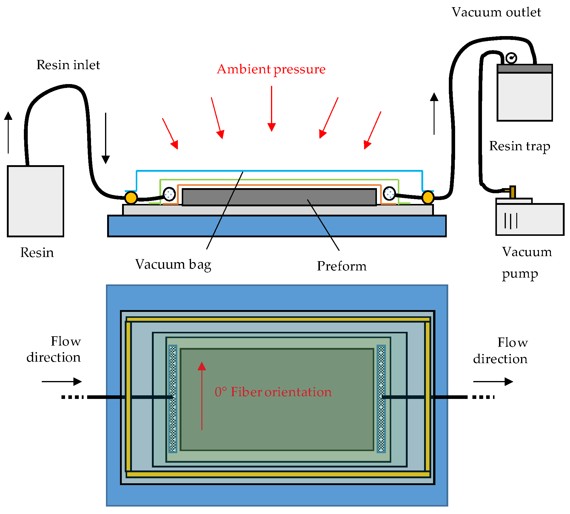
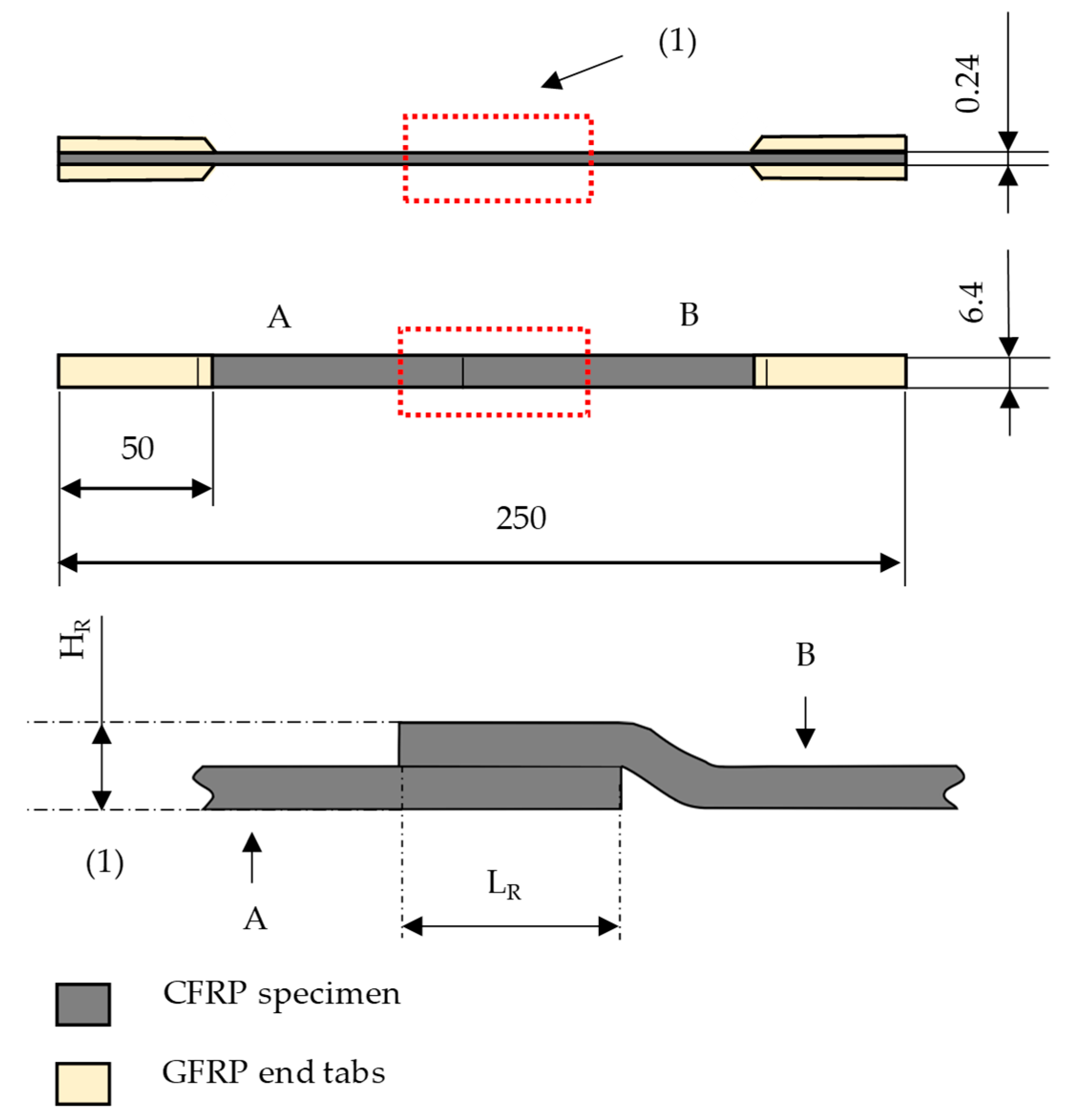
2.1.2. Sample Preparation
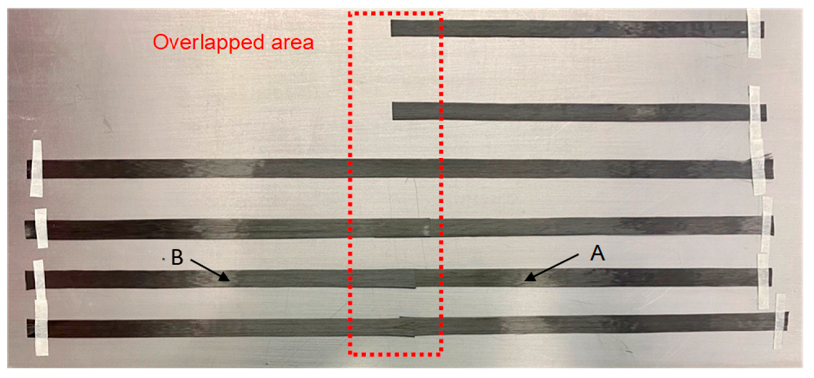
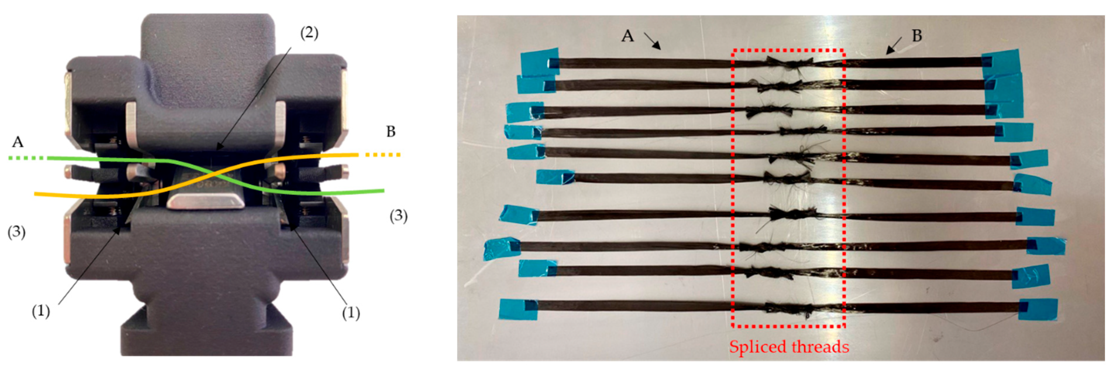
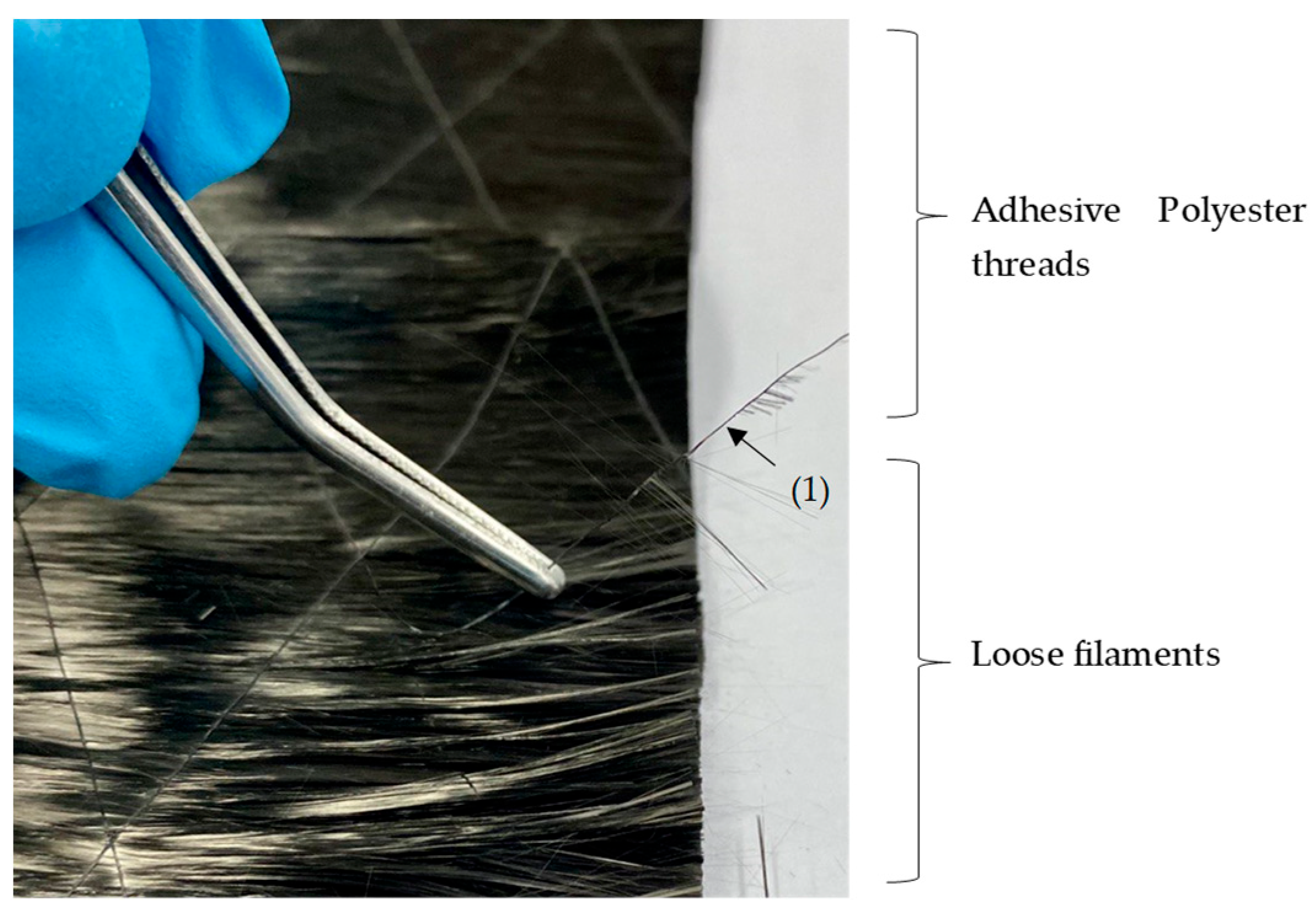
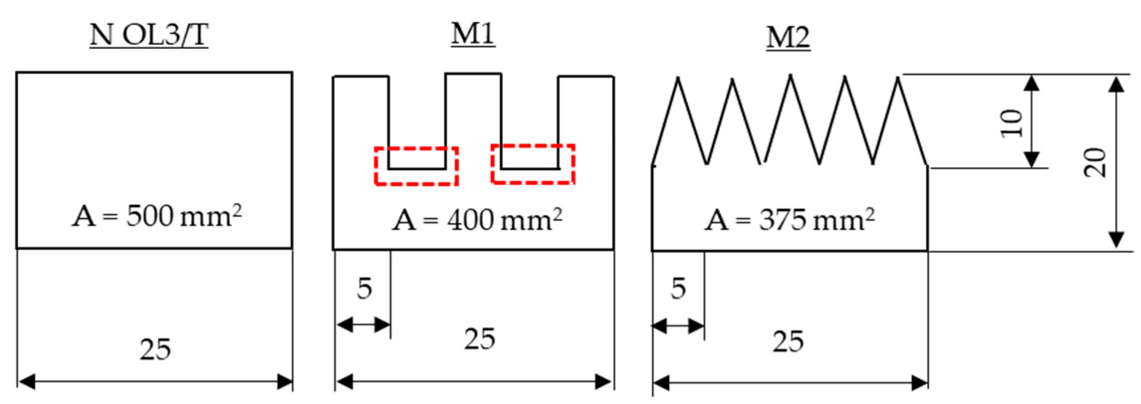
2.1.3. Composite A—Overlapping of Tows
2.1.4. Composite B—Single Layered
2.2. Methods
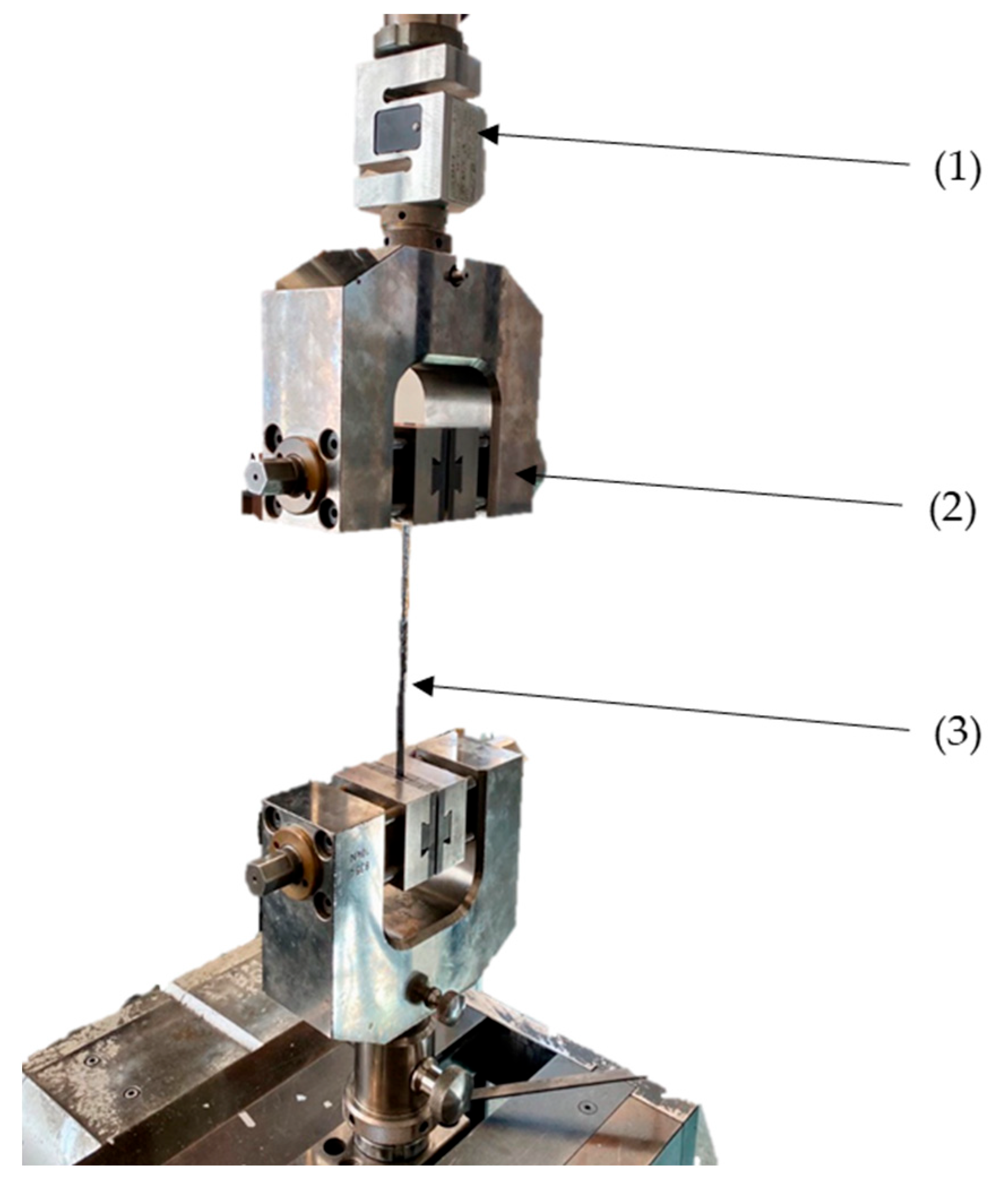
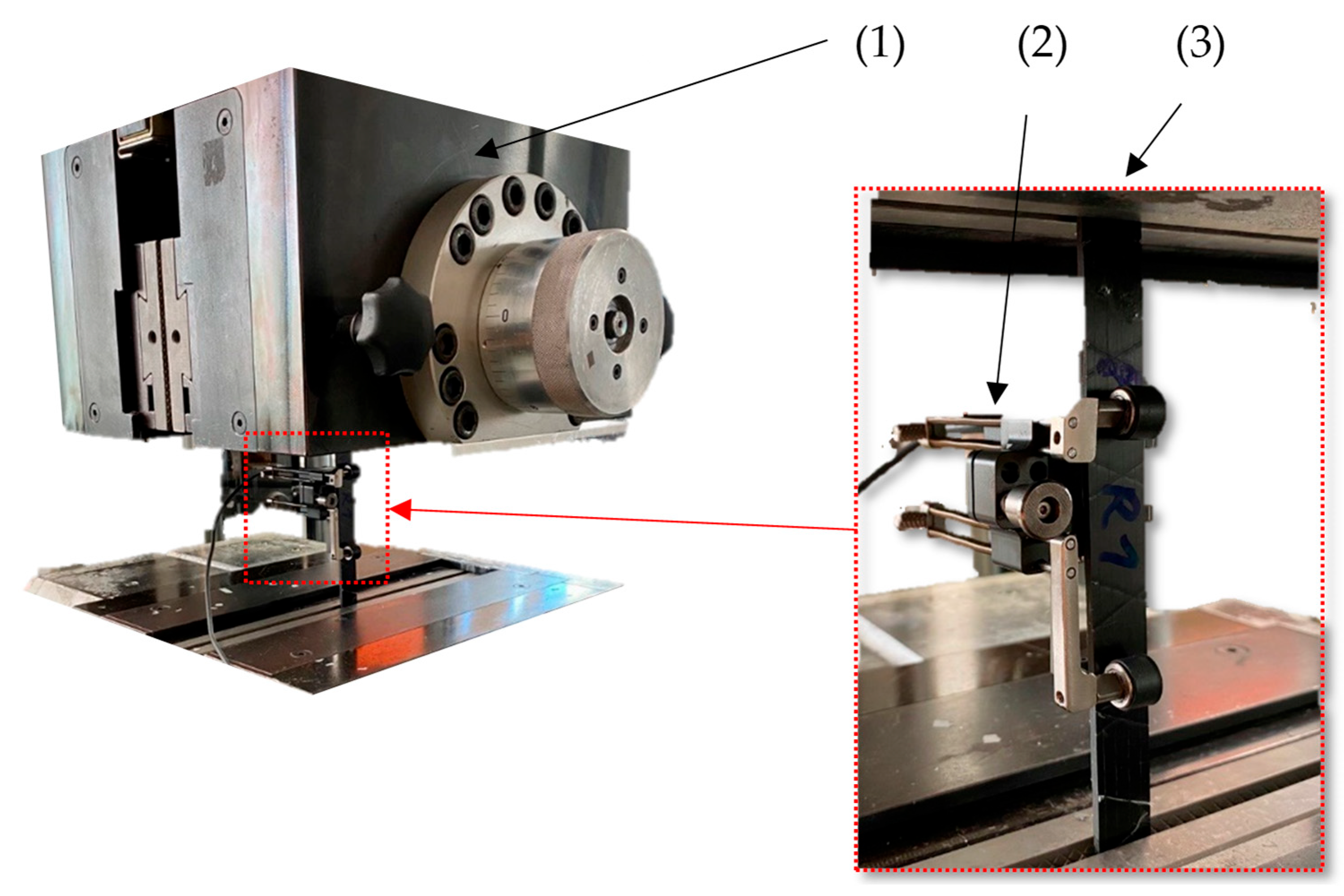
2.2.1. Tensile Testing
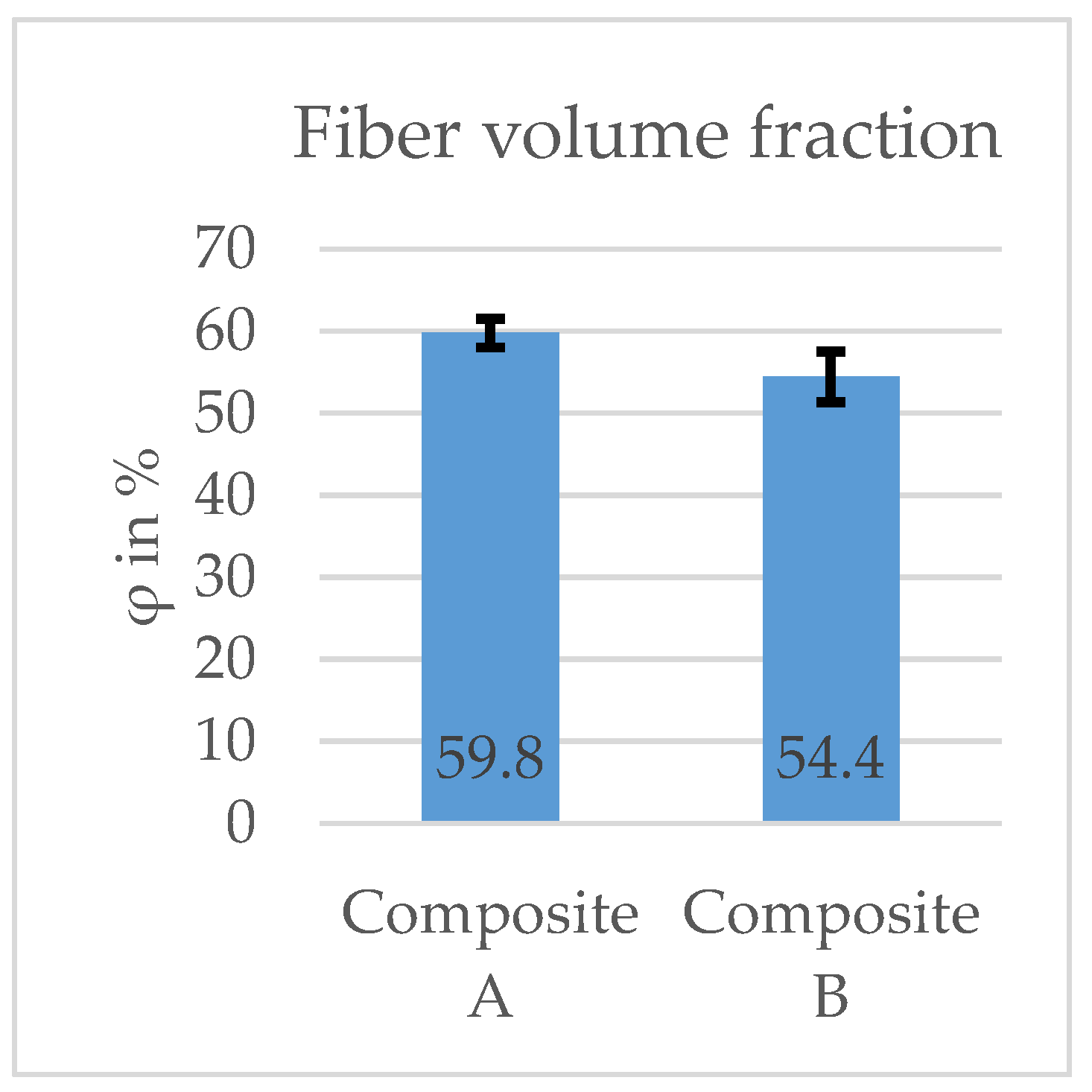
2.2.2. Fiber Volume Fraction
- mc: Mass of the samples before ignition of the matrix (g).
- mr,f: Residual mass of the samples (g)
- ρf: Density of the carbon fibers (g/cm3)
- ρm: Density of the matrix (g/cm3)
- Vf: Volume of the fibers (cm3)
- Vm: Volume of the matrix (cm3)
- φ: Fiber volume fraction of the composite (%).
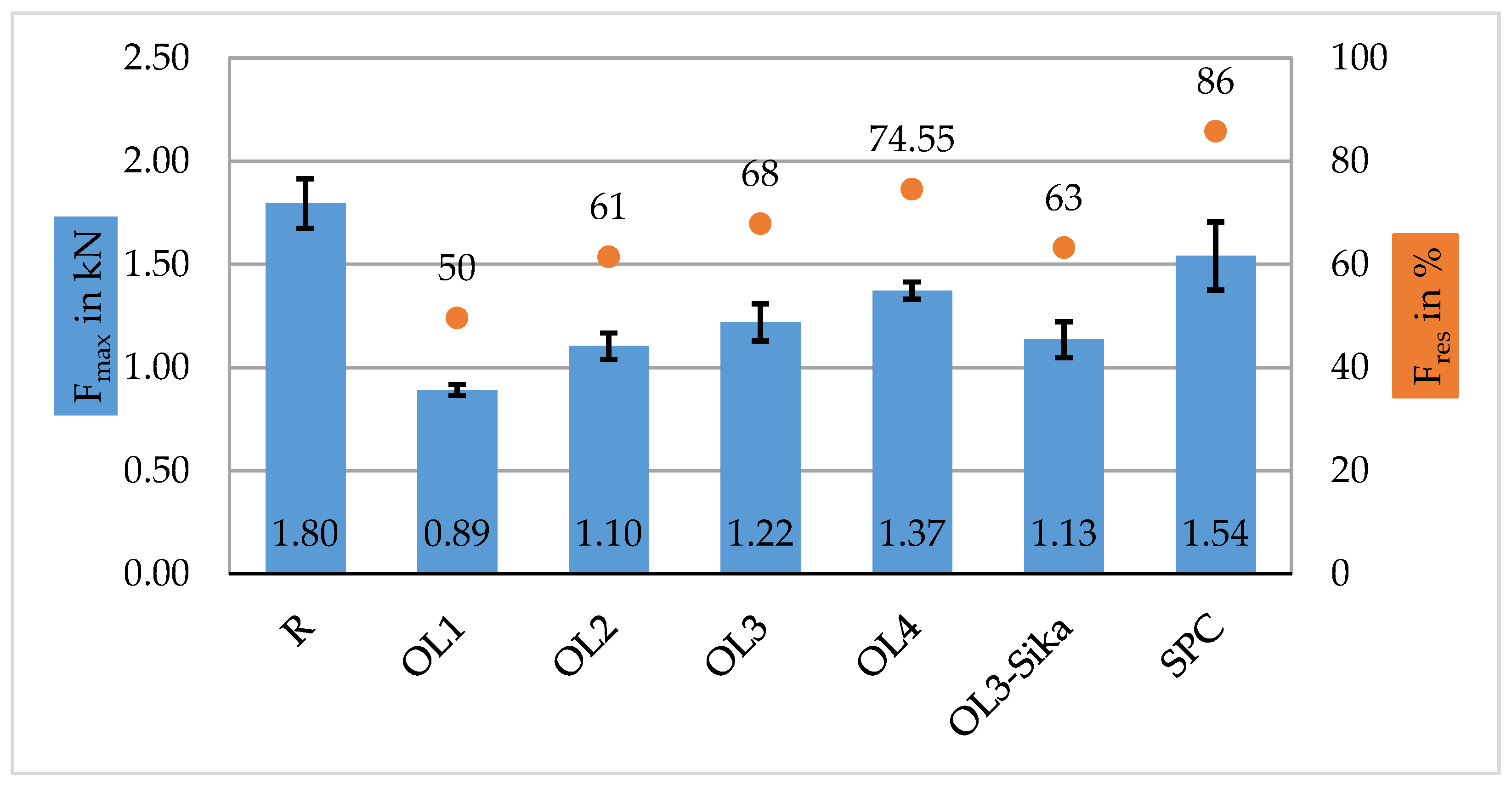
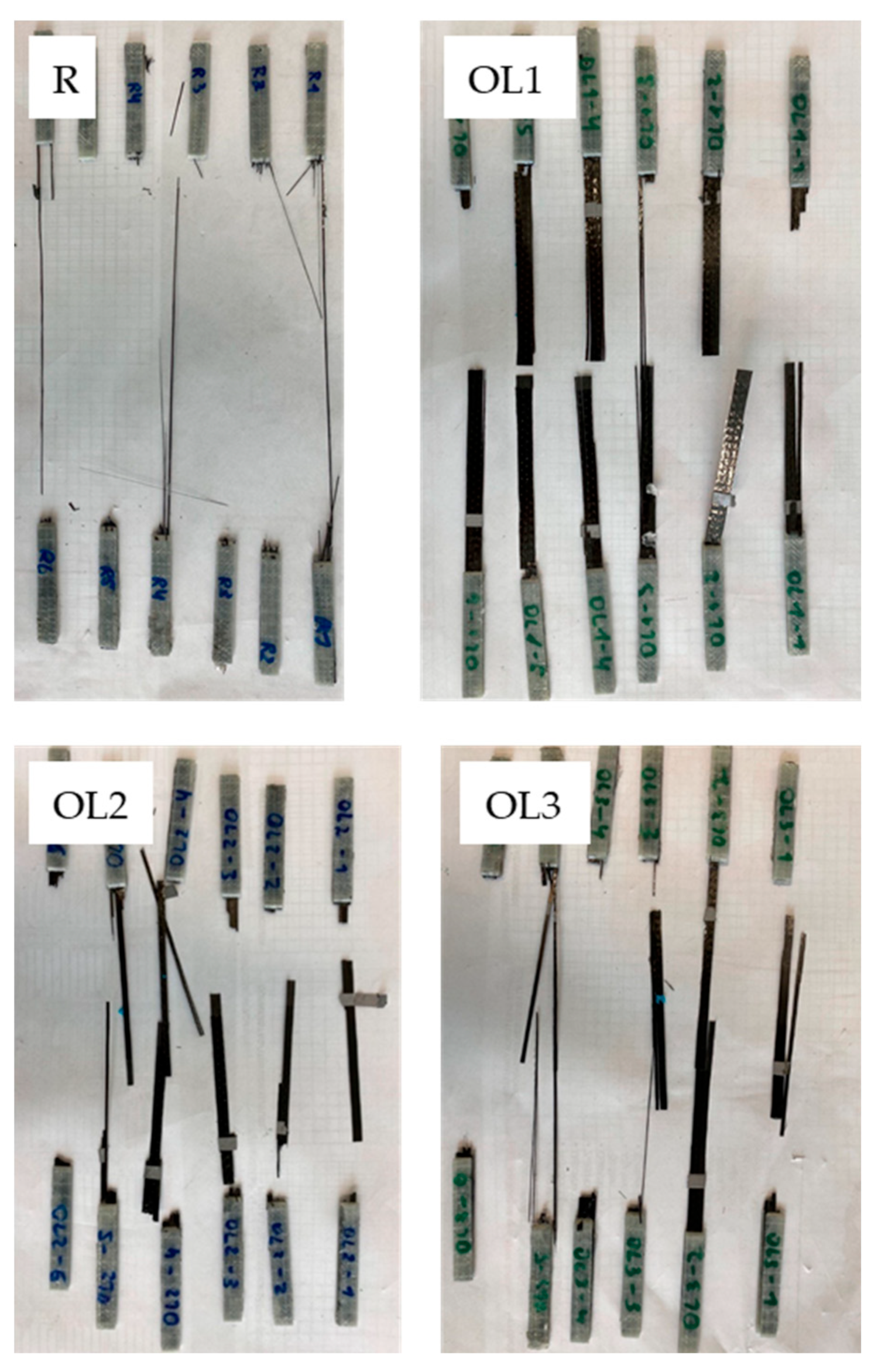
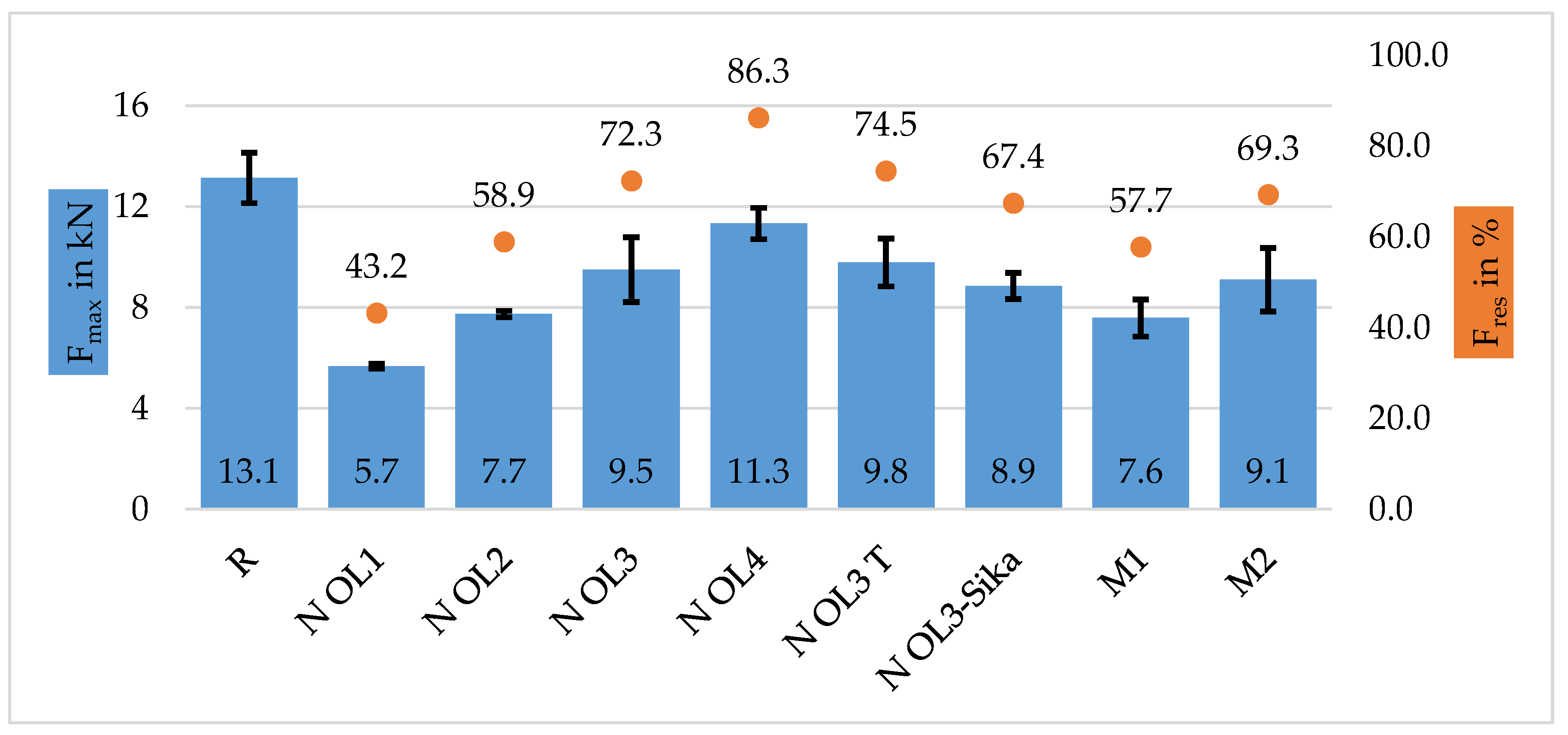
3. Results
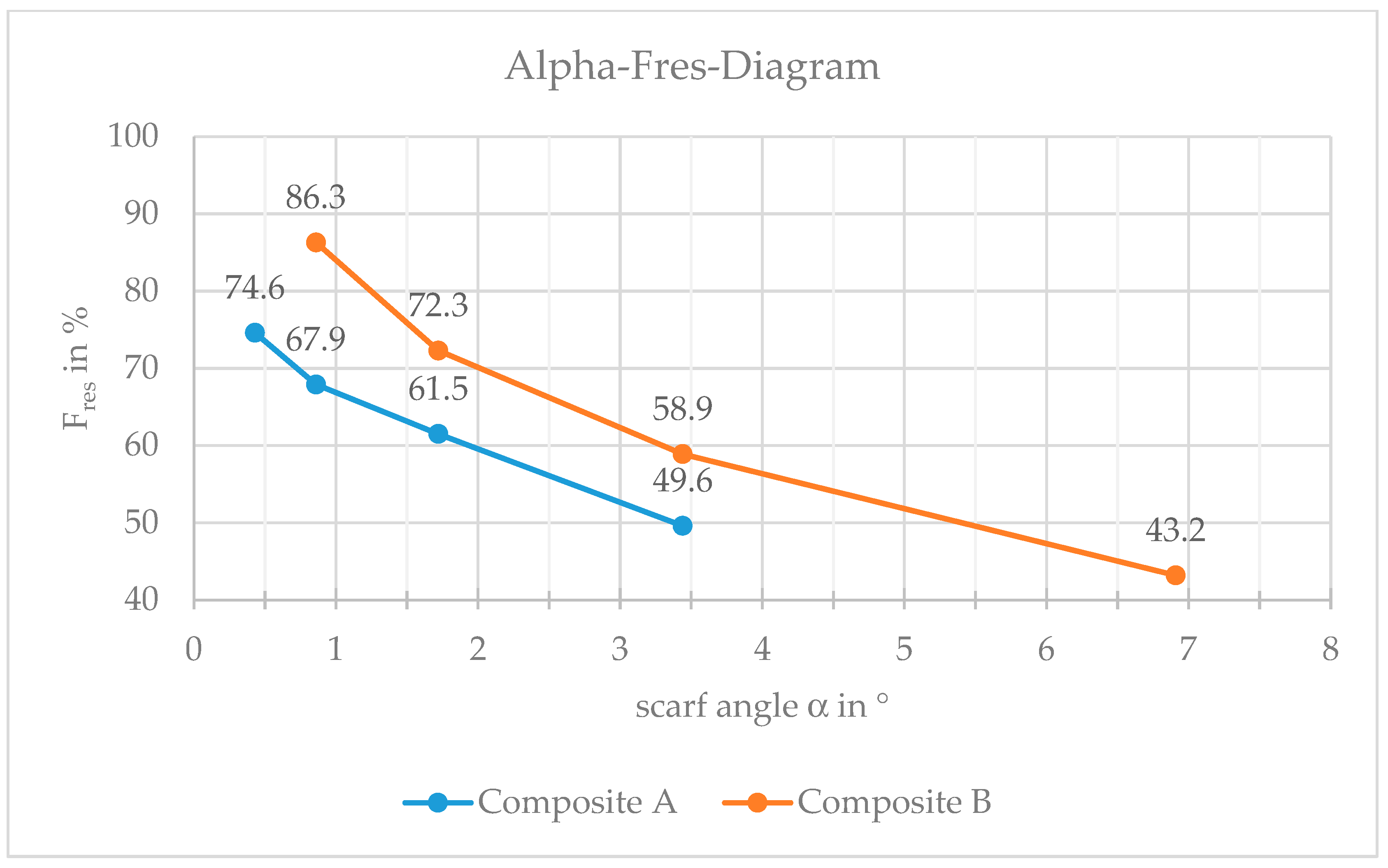
Tensile Testing
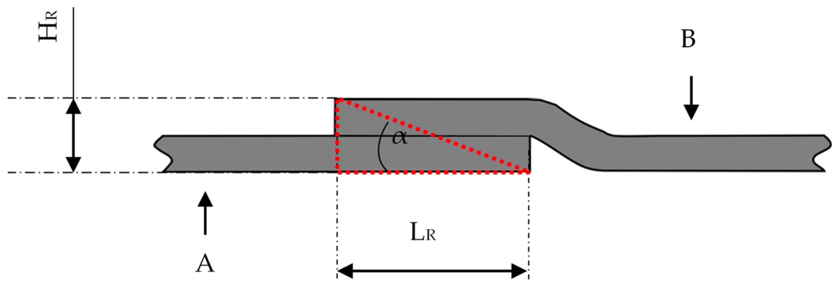
- α: Scarf angle (°).
- HR: Composite height at the repair area (mm).
- LR: Composite length of the repair area (mm).
4. Discussion
4.1. Composite A—Tow
4.2. Composite B—Single-Layered
5. Conclusions
Author Contributions
Funding
Institutional Review Board Statement
Informed Consent Statement
Data Availability Statement
Acknowledgments
Conflicts of Interest
References
- Lefeuvre, A.; Garnier, S.; Jacquemin, L.; Pillain, B.; Sonnemann, G. Anticipating in-use stocks of carbon fiber reinforced polymers and related waste flows generated by the commercial aeronautical sector until 2050. Resour. Conserv. Recycl. 2017, 125, 264–272. [Google Scholar] [CrossRef]
- Lefeuvre, A.; Garnier, S.; Jacquemin, L.; Pillain, B.; Sonnemann, G. Anticipating in-use stocks of carbon fibre reinforced polymers and related waste generated by the wind power sector until 2050. Resour. Conserv. Recycl. 2019, 141, 30–39. [Google Scholar] [CrossRef]
- Jacob, A. Carbon fibre and cars—2013 in review. Reinf. Plast. 2014, 58, 18–19. [Google Scholar] [CrossRef]
- Xiong, W.; Cai, C.S.; Xiao, R.C. 8—The use of carbon fiber-reinforced polymer (CFRP) composites for cable-stayed bridges. In Advanced Composites in Bridge Construction and Repair; Kim, Y.J., Ed.; Elsevier Science: Singapore, 2014; pp. 210–264. ISBN 978-0-85709-694-4. [Google Scholar]
- McConnell, V.P. Past is prologue for composite repair. Reinf. Plast. 2011, 55, 17–21. [Google Scholar] [CrossRef]
- Campilho, R.; de Moura, M.; Pinto, A.; Morais, J.; Domingues, J. Modelling the tensile fracture behaviour of CFRP scarf repairs. Compos. Part B Eng. 2009, 40, 149–157. [Google Scholar] [CrossRef]
- Gründer, M. Neues Reparaturverfahren. 6 February 2019. Available online: https://www.flugrevue.de/flugzeugbau/neues-reparaturverfahren-reparatur-von-cfk-bauteilen-bei-lufthansa-technik/ (accessed on 16 March 2021).
- Schmutzler, H. Repair Robot—Aircraft Composites|Lufthansa Technik. Available online: https://www.lufthansa-technik.com/caire-repair-robot (accessed on 16 March 2021).
- Pantelakis, S.; Tserpes, K. Revolutionizing Aircraft Materials and Processes, 1st ed.; Springer: Cham, Switzerland, 2020; ISBN 9783030353469. [Google Scholar]
- Heslehurst, R.B. Engineered Repairs of Composite Structures, 1st ed.; CRC Press, Taylor & Francis Group: Boca Raton, FL, USA, 2019; ISBN 9780429198656. [Google Scholar]
- Harder, S.; Röper, F.; Gibhardt, D.; Koert, B.; Fiedler, B. Strength of scarf-bonded CFRP repairs containing disc-shaped zones of weak bonding considering hot-wet conditioning. Int. J. Adhes. Adhes. 2020, 102, 102643. [Google Scholar] [CrossRef]
- Kim, H.-J.; Kim, H.-S.; Lee, G.-Y.; Kim, M.-S.; Min, S.-H.; Keller, R.; Ihn, J.-B.; Ahn, S.-H. Three-dimensional carbon fiber composite printer for CFRP repair. Compos. Part B Eng. 2019, 174, 106945. [Google Scholar] [CrossRef]
- Henning, F.; Moeller, E. (Eds.) Handbuch Leichtbau: Methoden, Werkstoffe, Fertigung; 2., überarbeitete und erweiterte Auflage; Carl Hanser Verlag GmbH & Co. KG: München, Germany, 2020; ISBN 978-3-446-45638-9. [Google Scholar]
- Ellerta, F.; Bradshaw, I.; Steinhilper, R. Major factors influencing tensile strength of repaired CFRP-samples. In Proceedings of the 9th CIRP Conference on Intelligent Computation in Manufacturing Engineering—CIRP ICME ‘14, Capri, Italy, 23–25 July 2014; pp. 275–280. [Google Scholar]
- Caminero, M.A.; Pavlopoulou, S.; Lopez-Pedrosa, M.; Nicolaisson, B.G.; Pinna, C.; Soutis, C. Analysis of adhesively bonded repairs in composites: Damage detection and prognosis. Compos. Struct. 2013, 95, 500–517. [Google Scholar] [CrossRef]
- Whittingham, B.; Baker, A.A.; Harman, A.; Bitton, D. Micrographic studies on adhesively bonded scarf repairs to thick composite aircraft structure. Compos. Part A Appl. Sci. Manuf. 2009, 40, 1419–1432. [Google Scholar] [CrossRef]
- Day, R. (Ed.) Proceedings of the Second International Workshop on Advanced Composite Materials and Technologies for Aerospace Applications, Wrexham, UK, 11–13 June 2012; North East Wales Institute: Wrexham, UK, 2012; ISBN 978-0-946881-76-5. [Google Scholar]
- Hoshi, H.; Nakano, K.; Iwahori, Y. (Eds.) Study on Repair of CFRP Laminates for Aircraft Structures. In Proceedings of the 16th International Conference on Composite Materials, Kyoto, Japan, 3–8 July 2007. [Google Scholar]
- Rabe, D.; Böhnke, P.R.C.; Kruppke, I.; Häntzsche, E.; Cherif, C. Novel Repair Procedure for CFRP Components Instead of EOL. Materials 2021, 14, 2711. [Google Scholar] [CrossRef] [PubMed]
- Böhnke, P.R.C.; Kruppke, I.; Hoffmann, D.; Richter, M.; Häntzsche, E.; Gereke, T.; Kruppke, B.; Cherif, C. Matrix Decomposition of Carbon-Fiber-Reinforced Plastics via the Activation of Semiconductors. Materials 2020, 13, 3267. [Google Scholar] [CrossRef] [PubMed]
- Sika. PDB-Biresin-CR83-inkl-DNV-GL-de. Available online: https://industry.sika.com/content/dam/dms/deaddconst01/5/PDB-Biresin-CR83-inkl-DNV-GL-de.pdf (accessed on 8 May 2023).
- Hexion Inc. EPIKOTE Resin MGS RIMR 135 and EPIKURE Curing Agent MGS RIMH 134–RIMH 137: Technicl Data Sheet; Hexion Inc.: Columbus, OH, USA, 2013. [Google Scholar]
- DIN EN ISO 527-4; Bestimmung der Zugeigenschaften. Deutsches Institut für Normung, Beuth Verlag GmbH: Berlin, Germany, 2020.
- Lord, P.R. Handbook of Yarn Production: Technology, Science and Economics; CRC Press: Boca Raton, FL, USA; Woodhead Publishing: Cambridge, UK, 2003; ISBN 0-8493-1781-9. [Google Scholar]


| Fiber Properties | Torayca T700S | Zoltek PX35 |
|---|---|---|
| Tensile strength (MPa) | 4900 | 4137 |
| Tensile modulus (GPa) | 230 | 242 |
| Elongation (%) | 2.1 | 1.5 |
| Density (g/cm3) | 1.80 | 1.81 |
| Mechanical Properties | RIMR135/ RIMH137 | CR83/ CH83-10 (-Sika) |
|---|---|---|
| Tensile strength (MPa) | 60–75 | 86 |
| Tensile modulus (GPa) | 2.7–3.2 | 3.1 |
| Elongation at break (%) | 8–16 | 7.9 |
| Flexural strength (MPa) | 90–120 | 131 |
| Impact strength (KJ/m2) | 70–80 | 83 |
| Compressive strength (MPa) | 80–90 | 109 |
| Density (g/cm3) | 1.18–1.20 | 1.15 |
| Subcategory | Overlap Length in mm | Note |
|---|---|---|
| OL1 | 5 | - |
| OL2 | 10 | - |
| OL3 | 20 | - |
| OL4 | 40 | - |
| OL3-Sika | 20 | Usage of nominal stronger resin system from “Sika” |
| SPC | ~20 | Mechanical connection on textile level by splicing with an air splicer |
| Subcategory | Overlap length LR in mm | Note |
|---|---|---|
| N OL1 | 5 | - |
| N OL2 | 10 | - |
| N OL3 | 20 | - |
| N OL4 | 40 | - |
| N OL3-Sika | 20 | Usage of nominal stronger resin system from “Sika” |
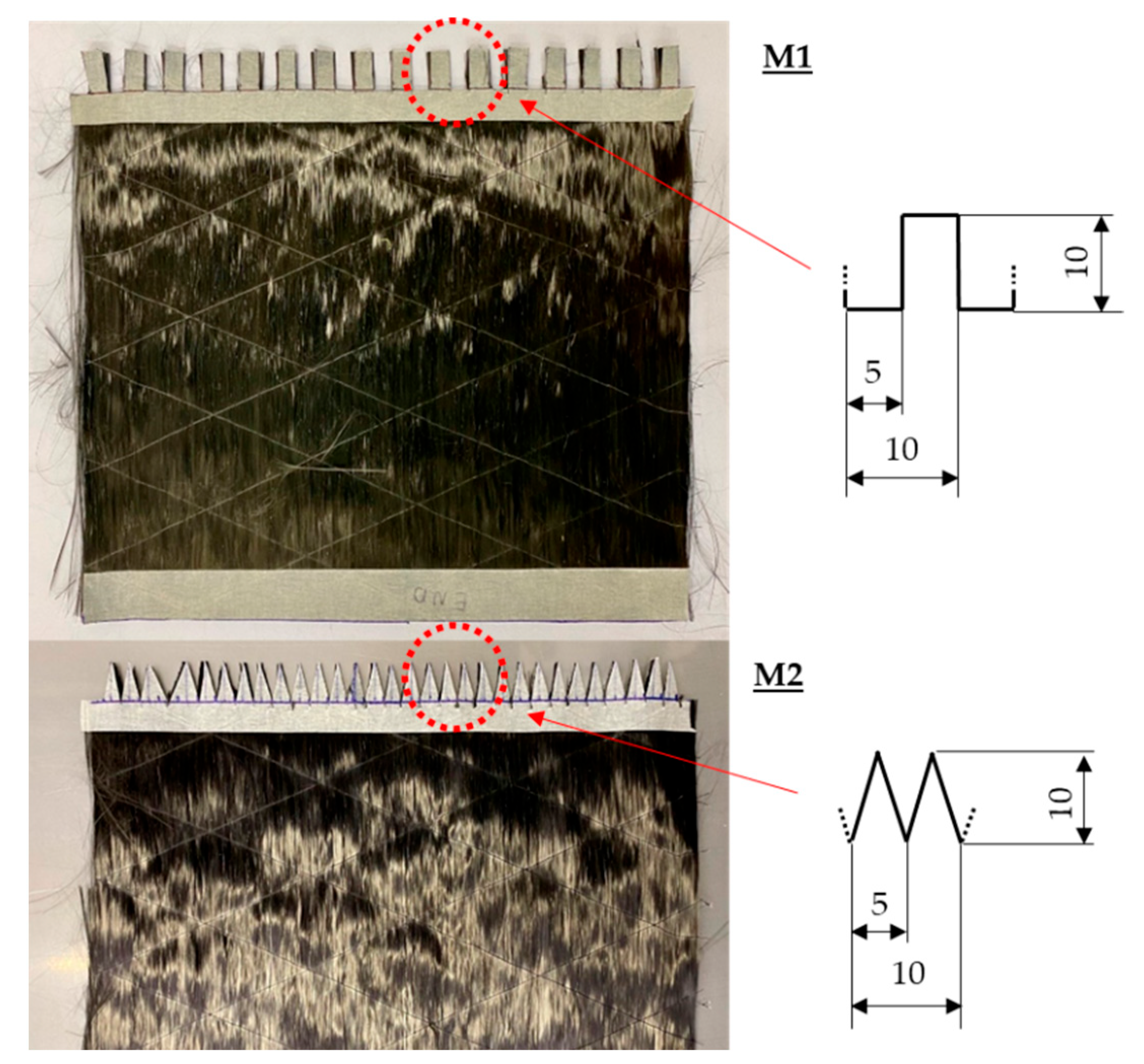
| M1 | ~20 | Modified edge geometry, rectangle pattern |
| M2 | ~20 | Modified edge geometry, triangle pattern |
Disclaimer/Publisher’s Note: The statements, opinions and data contained in all publications are solely those of the individual author(s) and contributor(s) and not of MDPI and/or the editor(s). MDPI and/or the editor(s) disclaim responsibility for any injury to people or property resulting from any ideas, methods, instructions or products referred to in the content. |
© 2023 by the authors. Licensee MDPI, Basel, Switzerland. This article is an open access article distributed under the terms and conditions of the Creative Commons Attribution (CC BY) license (https://creativecommons.org/licenses/by/4.0/).
Share and Cite
Rabe, D.; Arbulu, J.D.O.; Häntzsche, E.; Cherif, C. Investigation of the Bonding Mechanism between Overlapping Textile Layers for FRP Repair Based on Dry Textile Patches. Materials 2023, 16, 4680. https://doi.org/10.3390/ma16134680
Rabe D, Arbulu JDO, Häntzsche E, Cherif C. Investigation of the Bonding Mechanism between Overlapping Textile Layers for FRP Repair Based on Dry Textile Patches. Materials. 2023; 16(13):4680. https://doi.org/10.3390/ma16134680
Chicago/Turabian StyleRabe, David, Juan Daniel Ortega Arbulu, Eric Häntzsche, and Chokri Cherif. 2023. "Investigation of the Bonding Mechanism between Overlapping Textile Layers for FRP Repair Based on Dry Textile Patches" Materials 16, no. 13: 4680. https://doi.org/10.3390/ma16134680
APA StyleRabe, D., Arbulu, J. D. O., Häntzsche, E., & Cherif, C. (2023). Investigation of the Bonding Mechanism between Overlapping Textile Layers for FRP Repair Based on Dry Textile Patches. Materials, 16(13), 4680. https://doi.org/10.3390/ma16134680