
Low-Friction of ta-C Coatings Paired with Brass and Other Materials under Vacuum and Atmospheric Conditions

 , ,
, , 
Abstract
:1. Introduction
2. Materials and Methods
2.1. Sample Preparations
2.2. Tribological Experiments
2.3. Evaluation of Results
3. Results
3.1. Screening of Counterbodies in High Vacuum
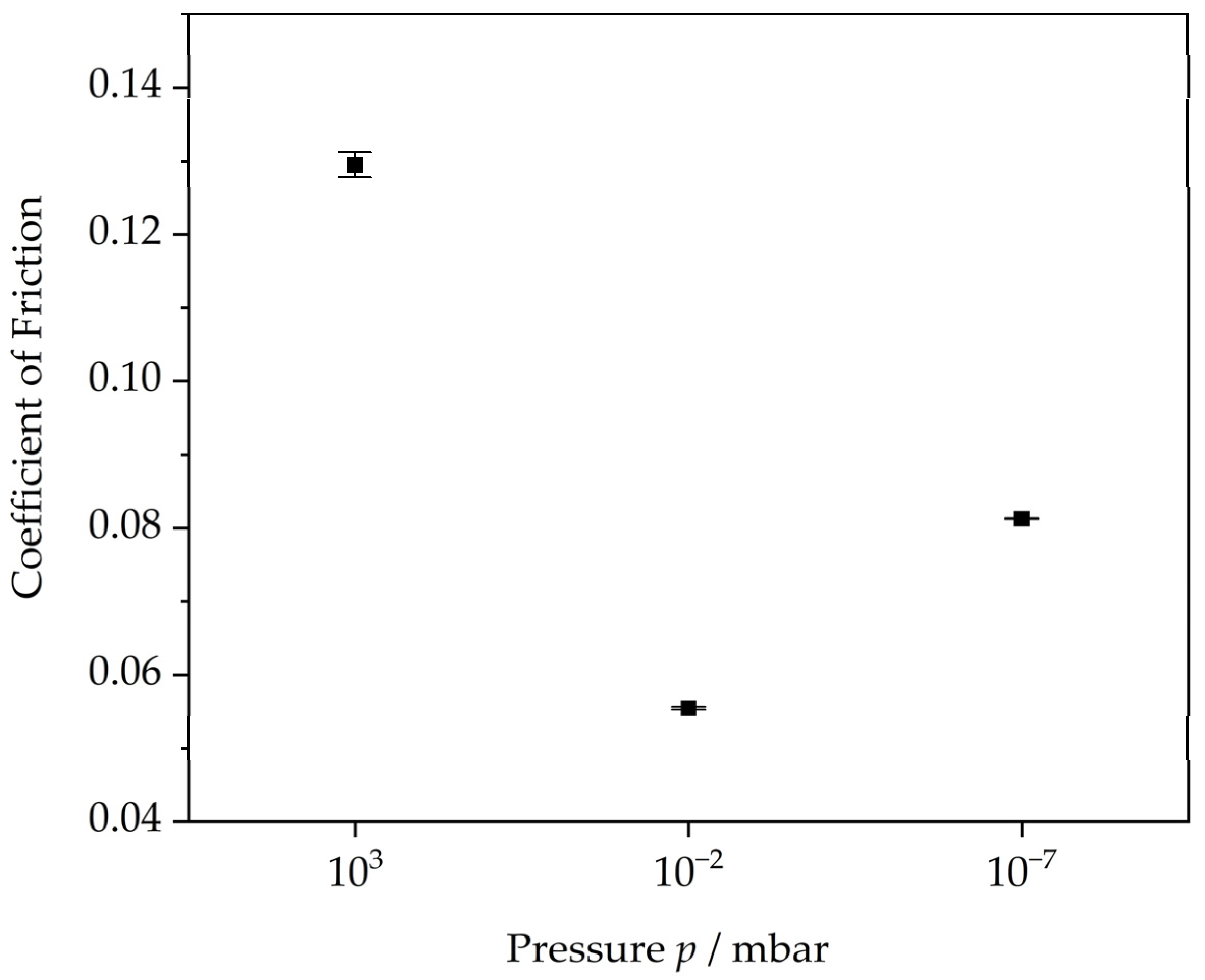
3.2. COF Evolution for the ta-C/Brass System in Vacuum and Atmospheric Conditions
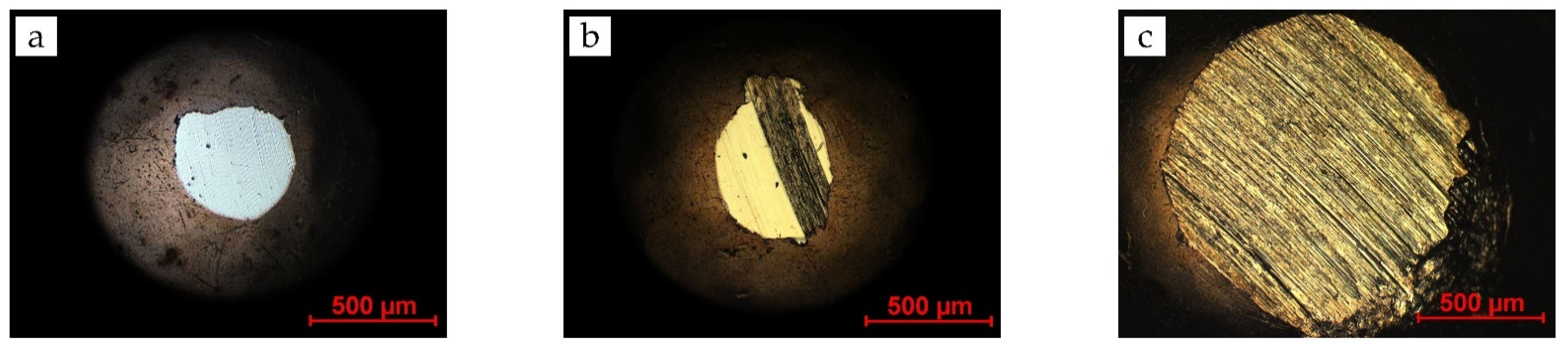
3.2.1. Wear Behavior of the Brass/ta-C Pairing
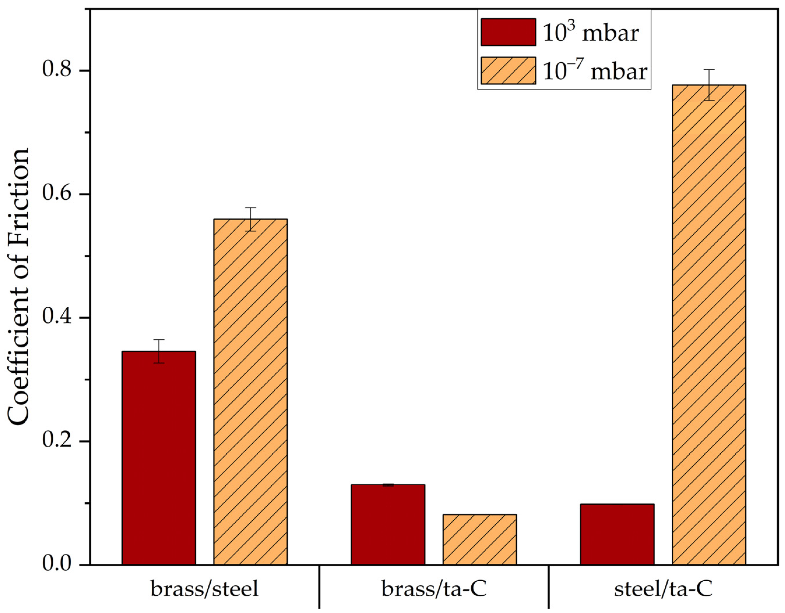
3.2.2. Comparison with Steel
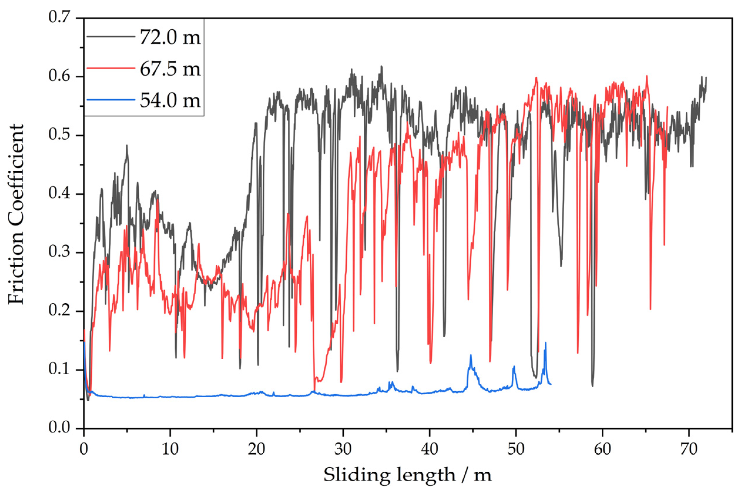
3.2.3. Long-Term Performance Experiments
4. Discussion
5. Conclusions
Author Contributions
Funding
Institutional Review Board Statement
Informed Consent Statement
Data Availability Statement
Conflicts of Interest
References
- International Organization for Standardization. ISO 20523:2017 Carbon Based Films—Classification and Designations; ISO: Geneva, Switzerland, 2017; Available online: https://www.iso.org/standard/68243.html (accessed on 17 February 2022).
- Weihnacht, V.; Brückner, A.; Bräunling, S. ta-C beschichtete Werkzeuge für die Trockenumformung von Aluminiumblechen. Vák. Forsch. Prax. 2008, 20, 6–10. [Google Scholar] [CrossRef]
- Klaffke, D.; Schultrich, B.; Weihnacht, V. Tribological behaviour of ta-C coatings under water lubricated conditions. Ann. Univ. Dunarea De Jos Galati 2005, 8, 24–28. [Google Scholar]
- Andersson, J.; Erck, R.A.; Erdemir, A. Frictional behavior of diamondlike carbon films in vacuum and under varying water vapor pressure. Surf. Coat. Technol. 2003, 163–164, 535–540. [Google Scholar] [CrossRef] [Green Version]
- Jang, Y.-J.; Kim, J.-I.; Lee, W.-Y.; Kim, J. Friction properties of thick tetrahedral amorphous carbon coating with different surface defects under dry contact conditions. Appl. Surf. Sci. 2021, 550, 149332. [Google Scholar] [CrossRef]
- Konicek, A.R.; Grierson, D.S.; Sumant, A.V.; Friedmann, T.A.; Sullivan, J.P.; Gilbert, P.U.P.A.; Sawyer, W.G.; Carpick, R.W. Influence of surface passivation on the friction and wear behavior of ultrananocrystalline diamond and tetrahedral amorphous carbon thin films. Phys. Rev. B 2012, 85, 155448. [Google Scholar] [CrossRef] [Green Version]
- Weihnacht, V.; Makowski, S.; Brückner, A.; Theiler, G.; Gradt, T. Tribologie und Anwendung trocken laufender ta-C-Schichten. Tribol. Schmier. 2012, 59, 41–44. [Google Scholar]
- Li, W.; Fan, X.; Li, H.; Zhu, M.; Wang, L. Probing carbon-based composite coatings toward high vacuum lubrication application. Tribol. Int. 2018, 128, 386–396. [Google Scholar] [CrossRef]
- Erdemir, A. The role of hydrogen in tribological properties of diamond-like carbon films. Surf. Coat. Technol. 2001, 146–147, 292–297. [Google Scholar] [CrossRef]
- Meunier, C.; Alers, P.; Marot, L.; Stauffer, J.; Randall, N.; Mikhailov, S. Friction properties of ta-C and a-C:H coatings under high vacuum. Surf. Coat. Technol. 2005, 200, 1976–1981. [Google Scholar] [CrossRef]
- Waesche, R.; Hartelt, M.; Weihnacht, V. Influence of counterbody material on wear of ta-C coatings under fretting conditions at elevated temperatures. Wear 2009, 267, 2208–2215. [Google Scholar] [CrossRef]
- Jang, Y.-J.; Kim, J.-I.; Lee, W.; Kim, J. Tribological properties of multilayer tetrahedral amorphous carbon coatings deposited by filtered cathodic vacuum arc deposition. Friction 2021, 9, 1292–1302. [Google Scholar] [CrossRef]
- Qi, Y.; Konca, E.; Alpas, A.T. Atmospheric effects on the adhesion and friction between non-hydrogenated diamond-like carbon (DLC) coating and aluminum—A first principles investigation. Surf. Sci. 2006, 600, 2955–2965. [Google Scholar] [CrossRef]
- Konca, E.; Cheng, Y.-T.; Weiner, A.M.; Dasch, J.M.; Alpas, A.T. Effect of test atmosphere on the tribological behaviour of the non-hydrogenated diamond-like carbon coatings against 319 aluminum alloy and tungsten carbide. Surf. Coat. Technol. 2005, 200, 1783–1791. [Google Scholar] [CrossRef]
- Banerji, A.; Bhowmick, S.; Alpas, A.T. High temperature tribological behavior of W containing diamond-like carbon (DLC) coating against titanium alloys. Surf. Coat. Technol. 2014, 241, 93–104. [Google Scholar] [CrossRef]
- Konca, E.; Cheng, Y.-T.; Weiner, A.M.; Dasch, J.M.; Alpas, A.T. Elevated temperature tribological behavior of non-hydrogenated diamond-like carbon coatings against 319 aluminum alloy. Surf. Coat. Technol. 2006, 200, 3996–4005. [Google Scholar] [CrossRef]
- Ni, W.; Cheng, Y.-T.; Weiner, A.M.; Perry, T.A. Tribological behavior of diamond-like-carbon (DLC) coatings against aluminum alloys at elevated temperatures. Surf. Coat. Technol. 2006, 201, 3229–3234. [Google Scholar] [CrossRef]
- Gharam, A.A.; Lukitsch, M.J.; Balogh, M.P.; Irish, N.; Alpas, A.T. High temperature tribological behavior of W-DLC against aluminum. Surf. Coat. Technol. 2011, 206, 1905–1912. [Google Scholar] [CrossRef]
- Konca, E.; Cheng, Y.-T.; Alpas, A.T. Dry sliding behaviour of non-hydrogenated DLC coatings against Al, Cu and Ti in ambient air and argon. Diam. Relat. Mater. 2006, 15, 939–943. [Google Scholar] [CrossRef]
- Konca, E.; Cheng, Y.-T.; Weiner, A.M.; Dasch, J.M.; Alpas, A.T. Vacuum tribological behavior of the non-hydrogenated diamond-like carbon coatings against aluminum: Effect of running-in in ambient air. Wear 2005, 259, 795–799. [Google Scholar] [CrossRef]
- Zhang, R.; Shen, M.; He, Z. The unusual tribological behavior of diamond-like carbon films under high vacuum. Surf Interface Anal 2020, 52, 339–347. [Google Scholar] [CrossRef]
- Kim, J.-I.; Jang, Y.-J.; Kim, J.; Kim, J. Effects of silicon doping on low-friction and high-hardness diamond-like carbon coating via filtered cathodic vacuum arc deposition. Sci. Rep. 2021, 11, 3529. [Google Scholar] [CrossRef]
- Gharam, A.A.; Lukitsch, M.J.; Qi, Y.; Alpas, A.T. Role of oxygen and humidity on the tribo-chemical behaviour of non-hydrogenated diamond-like carbon coatings. Wear 2011, 271, 2157–2163. [Google Scholar] [CrossRef]
- Bhowmick, S.; Banerji, A.; Alpas, A.T. Tribological behavior and machining performance of non-hydrogenated diamond-like carbon coating tested against Ti–6Al–4V: Effect of surface passivation by ethanol. Surf. Coat. Technol. 2014, 260, 290–302. [Google Scholar] [CrossRef]
- Kaulfuss, F.; Weihnacht, V.; Zawischa, M.; Lorenz, L.; Makowski, S.; Hofmann, F.; Leson, A. Effect of Energy and Temperature on Tetrahedral Amorphous Carbon Coatings Deposited by Filtered Laser-Arc. Materials 2021, 14, 2176. [Google Scholar] [CrossRef]
- Lorenz, L.; Chudoba, T.; Makowski, S.; Zawischa, M.; Schaller, F.; Weihnacht, V. Indentation modulus extrapolation and thickness estimation of ta-C coatings from nanoindentation. J. Mater. Sci. 2021, 56, 18740–18748. [Google Scholar] [CrossRef]
- Schneider, D.; Schwarz, T.; Scheibe, H.J.; Panzner, M. Non-destructive evaluation of diamond and diamond-like carbon films by laser induced surface acoustic waves. Thin Solid Film. 1997, 295, 107–116. [Google Scholar] [CrossRef]
- Schultrich, B. Tetrahedrally Bonded Amorphous Carbon Films I: Basics, Structure and Preparation; Springer: Berlin/Heidelberg, Germany, 2018; ISBN 9783662559277. [Google Scholar]
- Czichos, H. Tribologie-Handbuch: Tribometrie, Tribomaterialien, Tribotechnik, 3., Überarbeitete und Erweiterte Auflage; Vieweg + Teubner: Wiesbaden, Germany, 2010; ISBN 9783834896605. [Google Scholar]
- Nuruzzaman, D.M.; Chowdhury, M.A. Friction Coefficient and Wear Rate of Different Materials Sliding Against Stainless Steel. Int. J. Surf. Eng. Interdiscip. Mater. Sci. 2013, 1, 33–45. [Google Scholar] [CrossRef] [Green Version]
- Ferrari, A.C.; Robertson, J. Raman spectroscopy of amorphous, nanostructured, diamond-like carbon, and nanodiamond. Philos. Trans. A Math. Phys. Eng. Sci. 2004, 362, 2477–2512. [Google Scholar] [CrossRef] [PubMed]


| Counterbody Material | Vendor | Diameter and Grade | Roughness Ra/µm |
|---|---|---|---|
| Brass—CuZn35 | TIS Wälzkörpertechnologie Gauting, Germany | 10 mm, G200 | Ra < 0.203 µm |
| Silicon carbide SiC | SITUS Technicals Wuppertal, Germany | 10 mm, G25 | Ra < 0.051 µm |
| Aluminum oxide Al2O3 | Sd Hartstofftechnik Jestetten, Germany | 10 mm, G10 | Ra < 0.025 µm |
| Steel—1.3505 | TIS Wälzkörpertechnologie Gauting, Germany | 10 mm, G5 | Ra < 0.02 µm |
| Steel coated with ta-C | Fraunhofer IWS Dresden, Germany | 10 mm, not specified | Ra ≈ 0.1 µm |
| Copper | Shandong Yuncheng County Mingliang Steel Ball Factory, Heze, China | 10 mm, not specified | not specified |
| Bronze—CuSn6 | Ballcenter Handelsgesellschaft mbH & Co. KG, Neuhof, Germany | 9.525 mm, G200 | Ra < 0.203 µm |
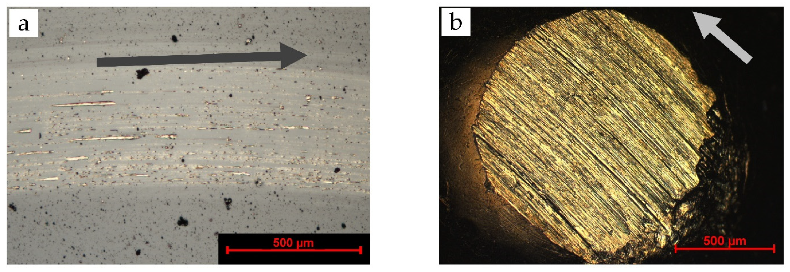
| Pressure | Disc Wear Track | Disc Raman Spectra | Counterbody Wear Scar | Counterbody Raman Spectra |
|---|---|---|---|---|
| 103 mbar | 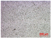 | 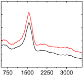 |  | 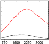 |
| 10−2 mbar |  |  | 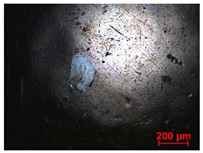 | 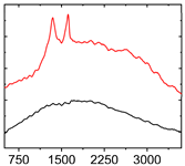 |
| 10−7 mbar | 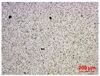 | No wear track visible |  | 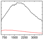 |
| Equivalent Distance | Friction Coefficient Average of Last 5 m | Specific Wear Rate/mm³/Nm | |
|---|---|---|---|
| Disc | Counterbody | ||
| 12.0 m | 0.08 ± 1.4 × 10⁻⁴ | 1 × 10⁻⁶ | 8.0 × 10⁻⁶ |
| 54.0 m | 0.08 ± 0.02 | 3 × 10⁻⁷ | 4.5 × 10⁻⁶ |
| 67.5 m | 0.52 ± 0.07 | 1.2 × 10⁻⁶ ± 6.9 × 10⁻⁷ | 6.9 × 10⁻⁵ |
| 72.0 m | 0.52 ± 0.03 | 2.9 × 10⁻⁶ ± 1.2 × 10⁻⁶ | 4.6 × 10⁻⁵ |
Publisher’s Note: MDPI stays neutral with regard to jurisdictional claims in published maps and institutional affiliations. |
© 2022 by the authors. Licensee MDPI, Basel, Switzerland. This article is an open access article distributed under the terms and conditions of the Creative Commons Attribution (CC BY) license (https://creativecommons.org/licenses/by/4.0/).
Share and Cite
Härtwig, F.; Lorenz, L.; Makowski, S.; Krause, M.; Habenicht, C.; Lasagni, A.F. Low-Friction of ta-C Coatings Paired with Brass and Other Materials under Vacuum and Atmospheric Conditions. Materials 2022, 15, 2534. https://doi.org/10.3390/ma15072534
Härtwig F, Lorenz L, Makowski S, Krause M, Habenicht C, Lasagni AF. Low-Friction of ta-C Coatings Paired with Brass and Other Materials under Vacuum and Atmospheric Conditions. Materials. 2022; 15(7):2534. https://doi.org/10.3390/ma15072534
Chicago/Turabian StyleHärtwig, Fabian, Lars Lorenz, Stefan Makowski, Matthias Krause, Carsten Habenicht, and Andrés Fabián Lasagni. 2022. "Low-Friction of ta-C Coatings Paired with Brass and Other Materials under Vacuum and Atmospheric Conditions" Materials 15, no. 7: 2534. https://doi.org/10.3390/ma15072534
APA StyleHärtwig, F., Lorenz, L., Makowski, S., Krause, M., Habenicht, C., & Lasagni, A. F. (2022). Low-Friction of ta-C Coatings Paired with Brass and Other Materials under Vacuum and Atmospheric Conditions. Materials, 15(7), 2534. https://doi.org/10.3390/ma15072534