Abstract
A combination of crash cushion and end-terminal, hybrid energy absorbing devices have been in use worldwide for a few years already. They include SafeEnd, a system Poland has recently introduced. Some road authorities have raised concerns as regards the operating conditions of the devices and how they work together with safety barriers. The objective of this research is to clarify the concerns and answer the following questions: (1) Can SafeEnd devices be used as hybrid devices and combine the roles of end-terminal and crash cushion placed before an obstacle? (2) What should be the rules for installing crash cushions at diverging roads and at the start of an off-ramp? The article presents characteristics of SafeEnd devices, defines the doubts raised by road safety auditors, discusses the results of field and numerical tests of the devices and explains the design principles for interchange ramps where crash cushions are required. The study results have helped to answer the research questions: SafeEnd devices fulfil the role of end-terminal and crash cushion, it is possible to make them more visible and principles have been defined for how the devices should be used at road interchanges. Further research should help to define general principles of deploying road restraint systems such as crashworthy terminals, crash cushions or hybrid devices.
1. Introduction
Roadsides are critical to road safety management. Roadside hazards represent one of the main causes of fatal accidents [1,2,3]. One of the ways to manage road safety is to use energy absorbers that prevent vehicles from running off the road [4,5].
Energy absorbers that act as crash cushions and end-terminals have been in use for a few years worldwide. The devices are designed to shield road barrier terminals and protect objects in the clear zone. Recently introduced in Poland, the energy absorber SafeEnd (SE) is an example of such devices. Some road authorities, however, have been raising concerns over their use as an energy absorber. Road authorities mainly object to the fact that:
- The SE system is not certified as a crash cushion,
- The SE is connected to barriers at interchange ramps in a way that increases the deflection of safety barriers from road edge; the result is that the barrier may be hit at more than 20 degrees which may increase the risk of barrier penetration and hitting an obstacle.
The article presents the results of research and SE operation analyses. It also looks at the possibilities and principles of using the devices as hybrid energy absorbers. Answers have been formulated to the research question: ‘Can SE devices be used as hybrid devices fulfilling the role of both an end-terminal, barrier terminal and crash cushion placed before an obstacle?’.
The work presented in the article covers an energy absorber which is a hybrid combination of the functions of a crashworthy terminal and crash cushion [6,7]. Crashworthy terminals are road safety devices, also known as energy absorbers, which are designed to reduce the severity of impact of a vehicle crashing into the start or end section of a road safety barrier [8,9]. They are characteristically permanently attached to the safety barrier. Crash cushions are devices designed to reduce the severity of impact of a car hitting a stationary obstacle (e.g., a bridge support) or entering an area at risk. There are two types of crash cushions: redirective and non-redirective [10,11]. A non-redirective cushion is designed to slow and contain an impacting vehicle. Its role is to take over the force whose direction is consistent with or similar to its design axis. It is used in locations where it is highly likely that a vehicle will impact the cushion head-on rather than from a high angle or from the side (e.g., toll booths on motorways). A redirective cushion during a side impact acts similarly to a safety barrier—it reduces the speed and kinetic energy of an impacting vehicle, changes its direction and puts it back in the expected direction (e.g., at the start of off-ramps).
When road restraint systems such as safety barriers with end-terminals or crash cushions are analysed for their applicability, the number one principle is to design roadsides that do not require such devices [12,13,14,15]. Hence the terms ‘safety zone’ or ‘clear zone’ which implies zones clear of obstacles that may lead to serious injury or fatality accidents [16,17,18,19]. This approach fits in with the idea of ‘forgiving roads’ [2,3,20].
The first research on crashworthy terminals and crash cushions dates back to the 1970s. J.G. Viner in his work highlighted the advantages of protecting the start sections of safety barriers and obstacles [21,22,23]. Bender and Zuker presented ways to protect barrier terminals and obstacles using interconnected water-filled cylinders [24]. In subsequent years, improvements were made to the technical parameters of end-terminals and crash cushions. Moreover, crash test standards were introduced for these devices [25,26]. Works carried out in the 1980s looked at the consequences of small vehicles impacting barrier terminals and pointed out that vehicle occupants suffered severe consequences [27]. In the 1980s, crashworthy terminals and crash cushions became widely used especially in the USA with research concentrating on their design and the consequences for car occupants [28,29]. In 1981 NCHRP 230 was developed, a report on procedures for testing road restraint systems [30]. Results of research were presented on the effects of safer barrier terminals on road user safety [31]. Zeeger pointed out that the individual elements of road infrastructure, including crash cushions, should be assessed for the hazard they pose which is a function of the likelihood that the particular element will be linked to an accident and its consequences [32]. Assessments of the hazards involved in barrier terminal impacts suggested that solutions are needed to mitigate the consequences of such an accident [33]. Solutions were sought to both improving safety and keeping maintenance costs low. As an example, analysis results were presented of the operation of a crashworthy terminal at the end of a concrete barrier [34] and a crash cushion with rubber elements [35]. Devices which until then were mostly used in the USA were picked up by other countries, e.g., in the UK which in 1987 installed the country’s first crash cushions on the Birmingham ringroad at so-called black spots (high accident risk spots) [36]. The results of research by Green et al. prove that safety barriers and crash cushions are also obstacles and should only be installed where accident consequences could be more severe in their absence [37]. Other research shows that as a priority action all hazardous obstacles should be removed from the roadside, and where impossible, barriers and crash cushions should be used [38]. In 1988, Ross presented ways to use field test results and numerical tests based on those tests to assess the technical parameters of barriers, their terminals and crash cushions [39]. In the late 1980s, the European standard EN 1317 is developed on road restraint systems which was subsequently improved [40,41,42]. In 1990 Proctor and Belcher suggest that the United Kingdom is still not fully convinced that crash cushions make sense and provided data which demonstrated that road safety could be significantly improved owing to the devices [43]. The 1990s, an increase in crash cushion application was seen in the Netherlands among others [44]. The period also marks the development of computer-based expert systems that support designers in their choice of restraint systems, including barrier terminals and crash cushions [45]. The work of Ries et al. presents the results of analyses of vehicle impact speeds into concrete barrier terminals and the consequences of such impacts [46]. In 1993, NCHRP 350 report was developed that normalised test procedures for road restraint systems [47]. Work is ongoing on new designs of crashworthy terminals such as the crashworthy terminal for box-beam and W-beam guardrails [48,49,50]. In his research, Elvik looks at how crash cushions and crashworthy terminals reduce accident severity [51]. Numerical tests of crashworthy terminals and crash cushions are developed [52,53]. Systems are built for terminal and crash accident data management [54,55]. In the new millennium, improvements are made to road-restraint systems making them more technologically advanced. In the USA, new guidelines are developed for road restraint systems called MASH [56] and followed when conducting crash tests of crash cushions [57,58]. The scope of numerical tests is extended. The tests are used as tools for verifying new solutions [4,59,60,61]. Authors work on improving numerical models ensuring that they best represent real test results. As an example in [62,63], the authors focussed on analysing cable barriers, works [64,65,66] covered steel guardrail barriers and [67,68,69] studied concrete safety barriers. In addition, innovative devices are tested that are partly built of plastics [70,71]. As well as barriers, numerical analyses are also used to study other road-safety devices, including terminals and crash cushions [72,73,74,75,76,77]. New technologies and research tools help to verify the effectiveness of the available devices [78,79,80,81,82] and confirm the effectiveness of road restraint systems [83]. Bligh and Mak point out that crash terminals should be tested for impacts into the most critical points [84]. Work zones are now protected using trailer-attenuating cushions [85,86,87]. Roper et al. states that the devices used in Australia, including terminal ends, should be replaced with safer solutions [88]. Crash terminals are improved [89,90,91], as well as cable barriers [92,93], concrete barriers [94], and crash cushions [95,96]. More economically efficient crash cushions are sought for use on roads with varying traffic volumes and traffic composition [97,98,99,100]. Effectiveness is also tested for device life cycle [101]. Crash cushions are becoming more and more prevalent [102]. Barrios et al. identifies the hazards to motorcyclists caused by safety barriers including barrier terminals and crash cushions [103]. Roque and Cardoso presented analysis results for impact severity levels on roads across Europe, including terminals and crash cushions and indicated that safer solutions are required [104]. There was a similar study in the USA by Johnson and Gabler [105]. Analyses of the effects of barriers and crash cushions on the level of road safety should also include the fact that the devices may affect sight distance [106]. Crash cushions at entrances to road tunnels were studied by Kunc et al. [107]. Other research points out that crash cushions are required to protect fixed roadside objects [108]. The work by Carrigan and Ray presents analyses of the frequency of specific types of crashworthy terminal impacts and compares real data with crash test data [109]. Ray and Carrigan applied meta-analysis to compare the consequences of crashworthy terminal collisions [110]. Other studies have assessed the effects of the distance between the terminal and traffic lane [111] and how different barrier terminals affect the safety of vehicle occupants [112]. Research by Meng et al. using numerical tests shows that damaged crashworthy terminals have an effect on accident consequences [113].
2. Materials and Methods
2.1. General Characteristics of Crash Cushions and Terminals
Energy absorbing devices are a group of road safety devices designed to absorb the energy of an impacting vehicle and, as a result, to reduce accident consequences which would occur if vehicles hit obstacles directly with no such protection. The main purpose of the devices is to change a potentially serious accident (involving fatalities or serious injuries) into a collision or a slight injury accident. Energy absorbers can be divided into:
Because the study conducted in this article covers a device which is certified for the European market, the standard EN 1317 [42] will be the document of reference.
The term crash cushion includes all devices that have successfully passed crash tests in accordance with the standard EN-1317-3 irrespective of the type of the material used and type of energy absorption. There are two types of crash cushions: redirective and non-redirective. A non-redirective cushion is designed to slow and contain an impacting vehicle. Its function is to take over the force whose direction is consistent or similar to its construction axis. It is installed in places where head-on vehicle collisions are highly likely as opposed to big angle or side collisions (such as in the case of motorway toll booths). In the case of impacts along the side a redirective cushion works similarly to a safety barrier. Its role is to reduce speed and kinetic energy of an impacting vehicle, change its direction and move it back to the expected direction of travel (cushions placed at the ‘nose’ of an interchange end-terminal).
Crash and energy-absorbing terminals are road safety devices whose function is to reduce the severity of impact when cars crash into the start or end section of a road safety barrier. They are one of the possible solutions for terminating barriers. There are many types of end-terminals to cater to the needs of different locations. The most common end-terminals include:
- Embedded in the counterscarp—do not absorb the kinetic energy of an impacting vehicle, deflected from barrier axis,
- Anchored in the ground—do not absorb the kinetic energy of an impacting vehicle,
- Absorb the kinetic energy of an impacting vehicle.
Some barrier terminals are unacceptable due to the hazard they pose to car occupants when the car hits the start or end of a barrier; in this case the barrier ends at guardrail level. Moreover, some of the ends that are turned down into the soil behave as launching ramps for impacting vehicles.
Crash terminals can be redirective or non-redirective, single-sided or double-sided and one way or two ways. While the principle of operation is similar as for crash cushions, the main difference is that the terminal must be connected to the safety barrier and the cushion can be independent and work without the barrier.
Hybrid energy absorbers are a type of road safety devices designed to reduce the severity of a crash when cars hit the start or end of a safety barrier and to provide certain functional features of crash cushions. Crash tests are required to confirm the performance expected of both a crash cushion and terminal.
To answer the research question (Do SafeEnd devices meet the requirements of a hybrid device?), SE device characteristics are presented as well as a list of crash tests, their results and the methodology and results of numerical tests.
2.2. SafeEnd Characteristics
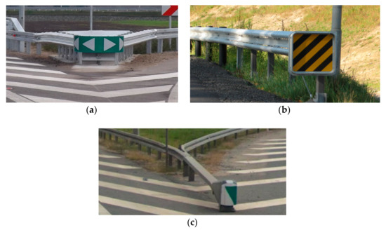
SE devices are made of steel elements and are corrosion-protected in a hot-dip galvanising process in accordance with the standard PN EN ISO 1461 [114]. The end part of the SE consists of: ‘backbone’ beam with a rectangular section with its front part placed almost at ground level and rising towards the ending; anchoring and support structure for the device; and a closed movable steel crash box (bumper) with a deformable frontal section (Figure 2 and Figure 3) whose role is to absorb the energy of a frontally impacting vehicle. The bumper is connected to the beam with a brake tensioning belt which goes through a set of brake cylinders in the lowest part of the beam.
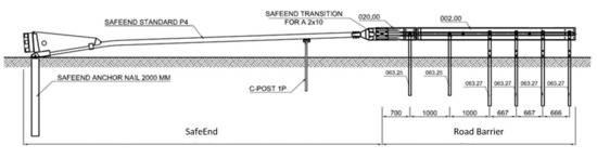
Figure 2.
SE geometric diagram and dimensions [mm].
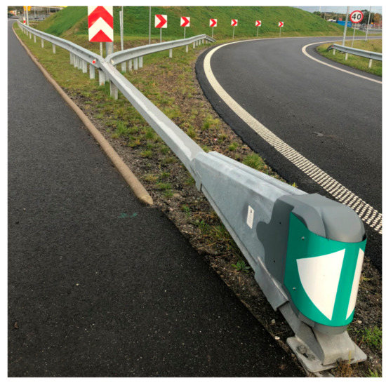
Figure 3.
Example of SE application.
SE devices are installed at the end of steel, concrete and cable barriers acting as crashworthy terminals or energy absorbing cushions U-15a. They are equipped with an amortising element (bumper) which absorbs the energy of the impact. When hit by a vehicle, the bumper deforms and is guided along the upper rail which runs in the direction of travel. Attached to the bumper is a brake tensioning belt. Upon impact the belt is pulled above the rolls together with the box and the entire absorption system is activated and gradually slows down as the vehicle motion resistance grows. As a result, the energy generated in the collision is absorbed and the vehicle is contained on a line defined by the length of the beam within the boundary level of overloads.
While SE devices may provide anchorage for safety barriers (fixed and temporary), when they take over the energy of an impacting vehicle (except side crashes into the transition) they act as a fully self-supporting structure and do not pass the forces onto the barrier. Depending on how safety barriers are installed, they may be used as double-sided, right-hand or left-hand barriers and redirective.
The SafeEnd is the start and end of safety barrier systems designed to absorb the kinetic energy generated by an impacting vehicle. Unlike barrier terminals that terminate in the ground, the SE keeps vehicles safer from being catapulted and rolling over. The SE can be used on single and dual carriageways, both on hard shoulders and central reservations where vehicles may hit the front of the barrier or where vehicles are known to collide frequently with barrier start sections. These devices cannot be used in locations where reverse-direction traffic may exist unless fully tested and evaluated in such a manner.
2.3. Research Methods
Road restraint system research is a complex process and one which requires diverse methods. These include statistical and mechanistic methods [115].
2.3.1. Statistical Methods
Statistical methods use available detailed data about dangerous road incidents to extract real cases of vehicles hitting safety barriers. Data are collected about the location of the incident, barrier design conditions, road traffic and other circumstances of the incidents. Next, using the data, mathematical models are built which define the relation between barrier functional parameters and the frequency and scale of vehicle crashes into barriers and of other significant factors [14,116,117].
Using the results of tests conducted under the LifeRoSE project [118], a detailed inventory was made of crash cushions and barrier end-terminals on selected sections of national roads. Table 1 presents the inventory.

Table 1.
Cushions and barrier end-terminals on sections of national roads.
Two indicators were used to compare the number of devices on sections of the different road classes: crash cushion density WOE and barrier terminal density WZB. This is the number of the devices per 100 km of a specific road class. Analysis of the results shows that per 100 km of road:
- On the network of national roads there are on average about 6 crash cushions and more than 90 barrier terminals,
- On the network of motorways there is on average about 1 crash cushion and more than 106 barrier terminals,
- On the network of express roads there are more than 10 crash cushions and more than 73 barrier terminals.
2.3.2. Mechanistic Methods
Field Tests
The standard EN 1317-3 [119] defines 6 crash tests for crash cushions of the highest performance class (Figure 4):
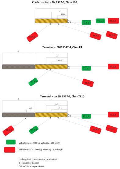
Figure 4.
Crash tests for crash cushions and terminals according to standards EN 1317-3, ENV 1317-4, pr EN 1317-7.
- Vehicle mass 900 kg, impact velocity 100 km/h: frontal impact at 0° (Test TC 1.1.100), frontal impact at 0° and ¼ vehicle offset (Test TC 2.1.100),
- Vehicle mass 1500 kg, impact velocity 110 km/h: frontal impact at 0° (Test TC 1.3.110), frontal impact at 15° (Test TC 3.3.110), side impact at 15° (Test TC 4.3.110), side impact at 165° (Test TC 5.3.110).
Two documents describe the rules for testing terminals. The first is ENV 1317-4 [120], that defines 4 crash tests for terminals of the highest performance class (Figure 4):
- Vehicle mass 900 kg, impact velocity 100 km/h: frontal impact at 0° and ¼ vehicle offset (test TT 2.1.100), side impact at 165° (test TT 5.1.110);
- Vehicle mass 1500 kg, impact velocity 110 km/h: frontal impact at 0° (Test TT 1.3.110), side impact at 15° (Test TT 4.3.110).
The second document is pr EN 1317-7 [121] (to replace ENV 1317-4), that defines 6 crash tests for terminals of the highest performance class (Figure 4):
- Vehicle mass 900 kg, impact velocity 100 km/h: frontal impact at 0° and ¼ vehicle offset (Test TT 2.1.100), side impact at 165° (Test TT 5.1.110),
- Vehicle mass 1500 kg, impact velocity 110 km/h: frontal impact at 0° (Test TT 1.3.110), frontal impact at 15° (Test TT 3.3.110), side impact at 15° (Test TT 4.3.110), side impact at 165° in combination with road safety barrier (Test TT 6.3.110).
Crash tests conducted in compliance with the standard prEN-1317 part 7, which is the more recent, more advanced and more rigorous test method for crashworthy terminals and transitions, confirm that the device operates properly and meets the criteria of the more accurate and more rigorous test procedure. The assessment method complies with prEN 1317-7 and ensures that the crash cushion was tested for all approaches by a test vehicle as required under EN 1317 part 3, i.e., 5 crash tests:
- Frontal approach, central impact at 0°,
- Frontal approach, impact at ¼ vehicle offset,
- Frontal approach, central impact at 15°,
- Side approach and impact at 15°,
- Side approach and impact at 165°,
nd in addition (not included in part 3 of EN 1317) a sixth crash test, i.e., a side impact at 165° into the transition between the crash cushion and road safety barrier.
The SE device was tested for 8 of 8 vehicle approaches to the crash cushion as defined in EN 1317 for the highest performance classes of crash cushions (Table 2). Traditional energy absorbers (crash cushions, crashworthy terminals) are mostly tested in 4 or 6 vehicle approaches to the device.
Table 2.
SE Crash tests.
The results of SE field tests are given in Section 3.2.
Numerical Tests
Test methodology. Numerical simulations are applied in many fields of engineering. They are tools which help to reduce the design costs because they keep prototyping to a necessary minimum. The design process happens in a virtual space which allows iterative improvements. To ensure the accuracy of a numerical model, a validation process must be conducted. This involves, among others, an objective comparison between real and virtual test results.
The finite element analyses (FEAs) were conducted using the LS-DYNA system (Livermore Software Technology Corporation) [122]. Today it is the most widely used software for numerical crash tests. To integrate the equations of motion, the LS-DYNA uses special form of explicit central difference method called the summed form. This algorithm works well especially for analysing strongly non-linear and rapidly changing phenomena that can comprise extended geometries and variable points of contact. Numerical simulations provide reliable tests of different configurations of vehicles impacting road safety devices and at the same time give good insight into the mechanics of the phenomena involved in the impact.
For the purposes of this work, the energy absorbing device SafeEnd was tested using selected numerical tests. The following activities were carried out:
- A numerical model of the SafeEnd energy absorbing device was developed,
- The results from a numerical simulation were validated against the results of an actual crash test,
- A parametric analysis was carried out of different impacts with the following variables: speed of impact, angle of impact, place of impact, configuration of the crash cushion-safety barrier relation.
Computational model. The crash test’s numerical model consists of the following elements: SafeEnd device, safety barrier, passenger car, soil and area over which the car moves. The model was designed to analyse vehicular impact into the side of the crash cushion, into the transition between the crash cushion and safety barrier and into a spot along the safety barrier.
The main parts of SafeEnd’s and the safety barrier’s computational model include the following: anchors, rectangular tube, steel box, C-post supporting the beam, transition between SafeEnd and safety barrier, posts and safety barrier profiles. The parts were modelled using shell finite elements (FEs). The average length of the side of a FE is app. 15 mm. The steel parts of road safety devices were assigned an elasto-visco-plastic material model with the strain-rate effects in accordance with the Cowper-Symonds model. That model also accounts for the effects of a damage prior to an element erosion. To discretise bolts, solid FEs were used with assigned damage criteria due to maximum forces and plastic strains. The device’s computational model was supplemented with a soil model in the form of a cylinder under each post. The soil was discretised with solid FEs. This is a common approach and relevant examples can be found in the literature, e.g., [66,123]. The car’s travel area is rigid and was modelled using shell FEs. The rectangular tube that terminates in the ground was constrained by fixing all degrees of freedom. This reflects the actual mounting of the device using a stiff tube anchor which transfers a large part of the impact energy and helps to disperse it in the ground. The discretisation of the SafeEnd device includes 141,192 nodes comprising 135,486 finite elements, of which 99,958 are shells and 35,528 are solids. Figure 5 shows the computational model setup.
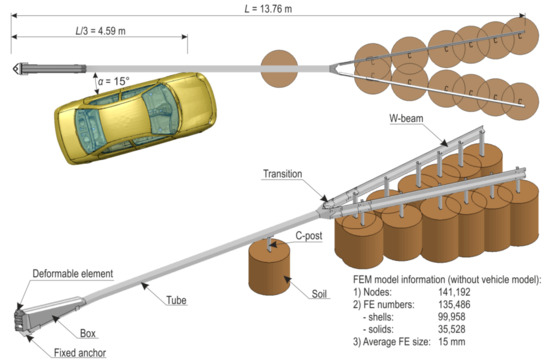
Figure 5.
Computational model of the SafeEnd—safety barrier—vehicle system.
Numerical simulations were conducted using the numerical model of a Dodge Neon vehicle whose weight is 1500 kg. The model is commonly used in numerical analyses (see e.g., [66]) and is generally available from on-line resources (open source). To improve its numerical stability, the vehicle was modified. The vehicle’s discretisation consists of 284,837 nodes and 271,614 finite elements, including 268,687 shells and 2853 solids.
The computations take account of the mass of the model parts and mass damping of the system. This helps to reduce non-physical vibrations of high frequencies which are characteristic of computations utilizing explicit central difference method. To simulate contact between the vehicle- road safety device-soil-road system, advanced algorithms are used which symmetrise contact using the penalty-based method.
Model validation. A simulation of a crash test of a SafeEnd energy absorbing device was conducted. The impact conditions are consistent with the test TC 4.3.110 in accordance with the standard PN-EN 1317-3:2010. They are as follows: velocity of impact 110 km/h, angle of impact 15°, place of impact at 1/3 of system length, i.e., 4.59 m from the beginning of the device (see Figure 5). Simulation results were compared with real crash test results.
In the numerical test after the vehicle had hit the crash cushion, it was contained and effectively redirected. Following the impact, the rectangular tube came off its support C-post and this post was bent down to the ground. Next, the vehicle hit the first two posts after the transition, bent and twisted them. The w-beam was deformed. Figure 6 and Figure 7 present a comparison between the numerical simulation and the real crash test. Figure 8 shows the deformation of the safety device obtained from the numerical simulation. In the Figure 6, Figure 7 and Figure 8 the soil in the form of the cylinders is visible. In the simulation the acceleration severity index ASI, which is a dimensionless index for defining the effect of the impact on car occupants, is 1.0 (0.96) (ASI = 1.0 in the real test). The theoretical head impact velocity THIV is 23 km/h (and THIV = 20 km/h in the real test). The vehicle comes into contact with the device along a section of 7.3 m (7.6 m in the real test).
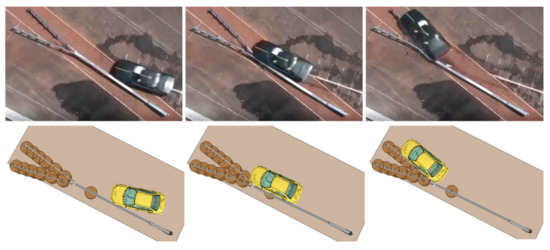
Figure 6.
Comparison of the real test (top) with the numerical simulation (bottom), top down view.
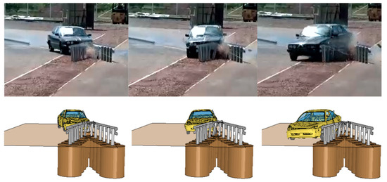
Figure 7.
Comparison of the real test (top) with the numerical simulation (bottom), front view.
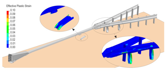
Figure 8.
Deformation of the system.
Setup of parametric analysis. After validating the numerical model, a parametric analysis was performed. For the parametric analyses, the model was adjusted, i.e., the safety barrier section was extended. In the model the barrier is installed on a horizontal curve. The discretisation of the numerical model for parametric analyses which consists of SafeEnd devices, the w-beam barrier, vehicle and the vehicle’s travel surface, consists of 589,568 nodes and 563,528 Fes. The simulations carried out were divided in two groups: impact into the SE device in the place as in the field test (Impact point 1), and impact into the road safety barrier on the horizontal curve of the road, in the place which results from the intersection of the barrier with a line parallel to the SE and distant from the SE device by 2.0 m (Impact point 2). The setup is presented in Figure 9. Within those two groups, different speeds and angles of the approach were tested. Additionally, the different radii of the arcs of the barrier connected to the system were also considered. The simulation results are presented in detail in Section 3.3 and discussed in Section 4.
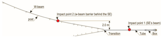
Figure 9.
Setup of parametric analysis.
3. Results
3.1. Statistical Analyses
The LifeRoSE database for 2017 includes nearly 220 incidents involving damage to barrier terminals and crash cushions. The highest number was recorded for barrier terminals ending in the ground (44.0% of all incidents) and crash cushions (39.4% of all incidents). Incidents involving other barrier terminals were the lowest at 6 incidents representing 2.8% of all incidents (Figure 10).
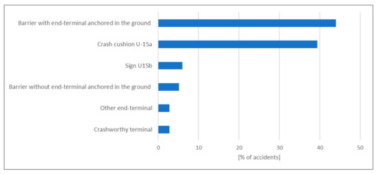
Figure 10.
Share of incidents involving safety barrier terminals [68].
There were 85 incidents involving energy absorbing devices, of which 79 were classified as collisions (93%) and 6 as road crashes (7%). More than 80% of crash cushion incidents involved frontal vehicular impacts.
Out of all LifeRoSE incidents, 6 involved hitting an SE (all of them were collisions). All cases of damaged SE devices were caused by frontal impacts of vehicles. In each of the recorded cases, SEs responded properly meaning that they reduced the consequences of vehicles crashing into an unsecured roadside object or obstacle.
The LifeRoSE project used a database of incidents involving road restraint systems which was made available by the General Directorate for National Roads and Motorways (the GDDKiA). Figure 11 presents examples of the consequences of vehicle collisions with SE devices.
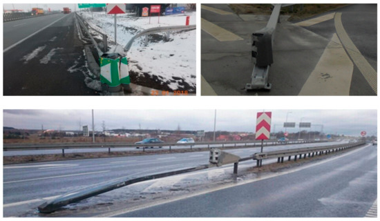
Figure 11.
Condition of SE devices after vehicle collisions (source: GDDKiA).
3.2. Field Tests
The SafeEnd device was tested to the standard prEN 1317 part 4 and the results demonstrate its proper performance as a crash cushion.
When the device was first tested in 2015 in Sweden (by the VTI research institute) to the standard prEN 1317- part 4 and 7, in all cases the results were positive, including the ASI parameter with the acceleration severity index at level B. The impact it refers to gives the worst ASI result, i.e., a side impact at 165° with a 900 kg vehicle (TT5.1.100) (Figure 12a). The test is carried out solely in a test procedure defined for safety barrier transitions and crash terminals. Tests of crash cushions include an analogous test, but with a 1500 kg vehicle (TC5.3.100). For all other tests the severity impact was in class A.
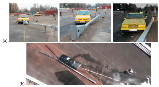
Figure 12.
Field tests (a) Sweden, (b) Poland.
The device was subsequently tested in 2020 in Poland (Research Institute of Roads and Bridges) to the harmonised most recent version of the standard EN 1317-3:2010 (Figure 12b). A set of tests was performed for the highest speed class of 110 km/h as set out in the standard. In all cases the results were positive including the ASI, i.e., impact severity at level A. This demonstrated that the SafeEnd energy absorbing device met all requirements defined in the standard PN-EN 1317-3 for the highest class of the reference speed.
The tests have helped to solve the research problem and demonstrated that SE devices can be used as hybrid energy absorbers which meet the role of both a safety barrier terminal and a crash cushion placed before a barrier.
Table 3 and Figure 13 show a cumulative list of the crash test results for a 900 kg vehicle and a 1500 kg vehicle.
Table 3.
Resulting test parameters for an SE device.
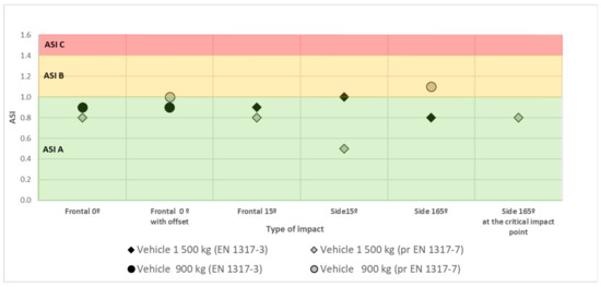
Figure 13.
Results of ASI tests from SE field crash tests.
3.3. Numerical Tests
To confirm the results of field tests, numerical tests were analysed. The results of numerical crash tests for the SE device were positive for ASI and THIV (Figure 14 and Figure 15):
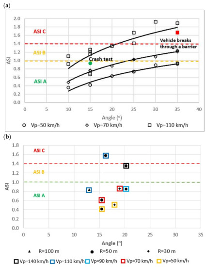
Figure 14.
ASI rates achieved in numerical simulations of a vehicle impacting: (a) the SE’s beam, (b) a safety barrier behind an SE.
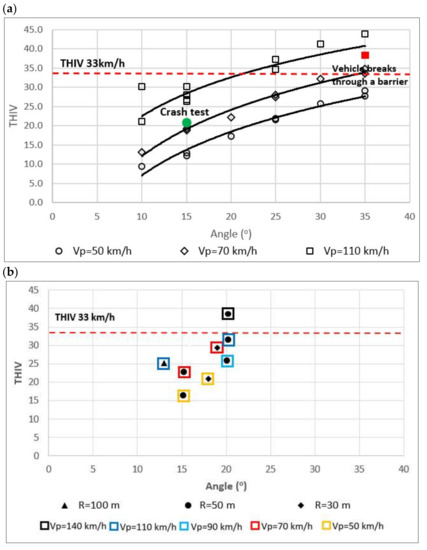
Figure 15.
THIV rates achieved in numerical simulations of a vehicle impacting: (a) the SE’s beam, (b) a safety barrier behind an SE.
- Vehicle impacting (vehicle mass 1500 kg) an SE device at different angles KAT (10°–35°) and at different impact speeds Vp (50 km/h, 70 km/h, 110 km/h),
- Vehicle impacting a section of the barrier after the transition to the SE device at KAT = 10° and impact speed Vp (50 km/h, 70 km/h, 110 km/h),
- Vehicle impacting laterally the barrier after the SE device at different angles KAT (10°–35°) and at different impact speeds Vp (50 km/h, 70 km/h, 110 km/h) and on ramps with a curve radius R (30 m; 50 m; 100 m).
4. Discussion
The answer to the research question ‘Can SE devices be used as hybrid devices fulfilling the role of both an end-terminal, barrier terminal and crash cushion placed before an obstacle?’ is affirmative. The arguments behind this claim are presented below.
The SafeEnd energy absorber successfully passed field crash tests that are required of crashworthy terminals (according to prEN 1317-4 and 7). The SafeEnd energy absorber successfully passed field crash tests that are required of crash cushions (according to PN-EN 1317-3).
In addition, the results of SafeEnd U-15a numerical crash tests were also positive.
In the case of a side impact into the SafeEnd’s beam, the simulation tests involved a vehicular impact (1500 kg vehicle mass) into the device at different angles KAT (10°–35°) and for different impact velocities Vp (50 km/h, 70 km/h, 110 km/h). The simulations established that:
- SE guardrail is not penetrated for velocity Vp = 110 km/h and angle not greater than 30°, and in the case of impact velocity below 110 km/h and angle up to 35° (Figure 15),
- The acceptable level of impact severity is (measured with ASI) for 110 km/h velocity and angle not greater than 25°, and in the case of impact velocity below 110 km/h at angle up to 35°,
- The acceptable level of driver’s head impact velocity THIV for 110 km/h and angle not greater than 25°, and in the case of impacts into the device at velocity below 110 km/h and angle up to 35°.
In the case of vehicle impact into the section of the barrier after the SafeEnd transition, the objective of the simulations was to test vehicle impact into the barrier at angle KAT = 10° and vehicle impact velocity Vp (50 km/h, 70 km/h, 110 km/h). Analysis of the simulations shows that the values of kinetic energy of the vehicle impact into the device and into the transition and impact severity indices are no different, i.e., the stiffness and performance of the transition are similar to that of the SafeEnd guardrail.
In the case side vehicle impacts into the barrier after the SafeEnd device, the objective of the simulations was to test vehicular impact into the barrier at different angles KAT (10°–35°) and for different impact velocities Vp (50 km/h, 70 km/h, 110 km/h) and at ramps with a curve radius R (30 m; 50 m; 100 m). The simulations were conducted for the following cases (Figure 16):
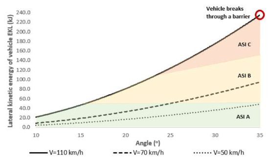
Figure 16.
Synthetic results of the effects of side impact angle KAT and velocity of vehicle impact Vp into the SafeEnd U-15a guardrail on lateral kinetic energy of vehicle EKL and impact severity rate ASI.
- Velocity of errant vehicle Vp = 110 km/h, on a ramp with a radius R = 100 m,
- Velocity of errant vehicle Vp = 70 km/h, on a ramp with a radius R = 50 m,
- Velocity of errant vehicle Vp = 50 km/h, on a ramp with a radius R = 30 m.
Analyses of the simulation tests and tests that the authors conducted under the RoSE research project (RID-3A) [2] established that:
- The safety barrier guardrail is penetrated by a vehicle for energy higher than 200 kJ, such lateral kinetic energy was not achieved in the simulation tests (Figure 17),
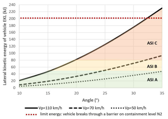 Figure 17. Relations between lateral kinetic energy EKL of a vehicle impacting a barrier placed after a SafeEnd device and vehicle velocity Vp (and related to ramp radius R) and impact angle KAT based on the simulation tests.
 - The acceptable impact severity level (measured with ASI) for 110 km/h and angle not greater than 15°, and in the case of impact velocity lower than 110 km/h at 35°.
Considering the test results, the SafeEnd energy absorber should be classified as an energy-absorbing device. Tested to the standard prEN 1317 part 7, the SE device was tested more rigorously than in the case of EN 1317 part 3 or 4. Because the device combines the technical performance and safety level of traditional crash cushions and crashworthy terminals, it is clearly an innovation. Its innovation lies in its ability to perform under specific conditions (e.g., on ramps) as a hybrid device, i.e., a crash cushion or crashworthy terminal and offers the advantages of both.
5. Conclusions
Numerous concerns were raised by General Directorate for National Roads and Motorways staff and auditors regarding SafeEnd crashworthy terminals and crash cushions placed at diverging lanes and ramps of express roads. Most of the objections had to do with SafeEnd used as a hybrid device combing the role of a crashworthy terminal and crash cushion placed before an obstacle and how it is connected with the barrier.
To clarify the doubts, the results of crash tests and simulation tests were evaluated, and the following conclusions were formulated:
- (1)
- The results of the field tests (crash tests) and numerical tests (simulation tests) and analyses of the results confirm that the SafeEnd U-15a energy absorbing device as an innovative hybrid device can be used as both a crashworthy terminal to protect barrier ends and a crash cushion to protect roadside obstacles under specific conditions.
- (2)
- The lateral kinetic energy of a barrier impacting vehicle and the impact severity level depend on the location of the SafeEnd energy absorbing device relevant to the road edge, emergency lane and at interchange ramps and on the speed of the vehicle and ramp radius (angle of vehicular impact into barrier).
Subsequent research should aim to define the location of crash cushions and hybrid devices on e.g., interchanges from the perspective of road safety.
Author Contributions
Conceptualisation M.B., K.J., G.B. and L.J.; methodology, M.B., K.J., L.J., D.B. and L.P.; validation, D.B. and L.P.; formal analysis L.J.; resources, G.B. and L.J.; data curation L.J.; writing—original draft preparation M.B., K.J. and L.J.; writing—review and editing M.B., K.J., L.J., D.B. and L.P.; project administration K.J., M.B. and G.B. All authors have read and agreed to the published version of the manuscript.
Funding
This research was funded by Saferoad RRS Polska, Wacława Balcerskiego 2 Street, 80-299 Gdańsk, Poland.
Institutional Review Board Statement
Not applicable.
Informed Consent Statement
Not applicable.
Data Availability Statement
Not applicable.
Conflicts of Interest
The authors declare no conflict of interest. The funders had no role in the collection, analyses, interpretation of data or in the decision to publish the results.
References
- Jamroz, K.; Budzyński, M.; Romanowska, A.; Żukowska, J.; Oskarbski, J.; Kustra, W. Experiences and Challenges in Fatality Reduction on Polish Roads. Sustainability 2019, 11, 959. [Google Scholar] [CrossRef] [Green Version]
- Roque, C.; Moura, F.; Cardoso, J.L. Detecting unforgiving roadside contributors through the severity analysis of ran-off-road crashes. Accid. Anal. Prev. 2015, 80, 262–273. [Google Scholar] [CrossRef] [PubMed]
- La Torre, F.; Saleh, P.; Cesolini, E.; Goyat, Y. Improving Roadside Design to Forgive Human Errors. Procedia Soc. Behav. Sci. 2012, 53, 235–244. [Google Scholar] [CrossRef] [Green Version]
- Budzynski, M.; Jamroz, K.; Wilde, K.; Witkowski, W.; Jelinski, L.; Bruski, D. The role of numerical tests in assessing road restraint system functionality. Eur. Transp. Res. Rev. 2020, 12, 30. [Google Scholar] [CrossRef]
- Cafiso, S.; D’Agostino, C.; Persaud, B. Investigating the influence on safety of retrofitting Italian motorways with barriers meeting a new EU standard. Traffic Inj. Prev. 2016, 18, 324–329. [Google Scholar] [CrossRef]
- American Association of State Highway and Transportation Officials (AASHTO). Roadside Design; American Association of State Highway: Washington, DC, USA, 2011. [Google Scholar]
- O’Callaghan, N.; Aulmann, P.; Chia, S. Austroads Guide to Road Design Part 6B: Roadside Environment; Austroads: Sydney, NSW, Australia, 2015. [Google Scholar]
- Mak, K.K.; Bligh, R.P.; Ross, H.E., Jr.; Sicking, D.L. Slotted rail guardrail terminal. Transp. Res. Rec. 1995, 1500, 43–51. [Google Scholar]
- Sicking, D.L.; Reid, J.D.; Rohde, J.R. Development of a Sequential Kinking Terminal for W-Beam Guardrails. Transp. Res. Rec. J. Transp. Res. Board 1998, 1647, 89–96. [Google Scholar] [CrossRef]
- Thomson, R.; Fagerlind, H.; Martinez, A.V.; Amenguel, A. Roadside Infrastructure for Safer European Roads: D06 European Best Practice for Roadside Design: Guidelines for Roadside Infrastructure on New and Existing Roads; Project RISER, European Community; Chalmers University of Technology: Göteborg, Sweden, 2006. [Google Scholar]
- Jurewicz, C.; Steinmetz, L.; Phillips, C.; Cairney, P.; Veith, G.; McLean, J. Improving Roadside Safety Summary Report; Austroads: Sydney, NSW, Australia, 2014. [Google Scholar]
- Budzyński, M.; Jamroz, K.; Jeliński, Ł.; Gobis, A. The Effects of Roadside Hazards on Road Accident Severity. J. Konbin 2019, 49, 319–339. [Google Scholar] [CrossRef] [Green Version]
- Central Asia Regional Economic Cooperation (CAREC). CAREC Road Safety Engineering Manual 1–Road Safety Audit; Asian Development Bank: Mandaluyong, Philippine, 2018. [Google Scholar]
- Fitzpatrick, C.D.; Harrington, C.P.; Knodler, M.A., Jr.; Romoser, M.R.E. The influence of clear zone size and roadside vegetation on driver behavior. J. Saf. Res. 2014, 49, 97.e1–104. [Google Scholar] [CrossRef]
- Gülich, H.A. Terminals of guardrails and walls on roadsides—Necessary limitation of protection. Bautechnik 1999, 76, 135–145. [Google Scholar] [CrossRef]
- Jamieson, N.J.; Waibl, G.; Davies, R. Use of Roadside Barriers Versus Clear Zones; NZ Transport Agency Research: Wellington, New Zealand, 2011. [Google Scholar]
- Budzynski, M.; Jamroz, K.; Antoniuk, M. Effect of the Road Environment on Road Safety in Poland. IOP Conf. Ser. Mater. Sci. Eng. 2017, 245, 042065. [Google Scholar] [CrossRef]
- Jurewicz, C.; Steinmetz, L. Crash performance of safety barriers on high-speed roads. J. Australas. Coll. Road Saf. 2012, 23, 37–44. [Google Scholar]
- Budzynski, M.; Jamroz, K.; Jelinski, L.; Antoniuk, M. Why are trees still such a major hazard to drivers in Poland? Transp. Res. Procedia 2016, 14, 4150–4159. [Google Scholar] [CrossRef] [Green Version]
- CEDR. Forgiving Roadsides Design Guide; Conference of European Directors of Roads: Paris, France, 2012. [Google Scholar]
- Viner, J.G. Experience to date with impact attenuators. Pub. Roads 1971, 36, 209–218. [Google Scholar]
- Viner, J.G. Recent Developments in Roadside Crash Cushions. Transp. Eng. J. ASCE 1972, 98, 71–87. [Google Scholar] [CrossRef]
- Viner, J.G.; Tamanini, F. Effective highway barriers. Accid. Anal. Prev. 1973, 5, 203–214. [Google Scholar] [CrossRef]
- Bender, L.E.; Zucker, S.H. Water-cushioned ‘gore areas’ reduce deadly vehicle impacts. Am. City 1973, 88, 5. [Google Scholar]
- Bronstad, M.E.; Michie, J.D. Recommended procedures for vehicle crash testing of highway appurtenances. Highw. Res. Board. Natl. Coop. Highw. Res. Progr. Rep. 1974, 153, 1–30. [Google Scholar]
- Michie, J.D. Recommended procedures for the safety performance evaluation of highway appurtenances. Natl. Coop. Highw. Res. Progr. Rep. 1981, 230, 1–48. [Google Scholar]
- Carney, J.F. Minisized Automobiles and Roadside Appurtenances. J. Transp. Eng. 1983, 109, 815–823. [Google Scholar] [CrossRef]
- Marquis, E.L.; Peterson, R.T. Box-beam guardrail terminal section. Transp. Res. Rec. 1983, 942, 37–42. [Google Scholar]
- Bronstad, M.E. Guardrail ends. In Proceedings of the 27th Annual Conference, San Antonio, TX, USA, 3–6 October 1983; pp. 389–407. [Google Scholar]
- Michie, J.D. Raport NCHRP 23O—Recommended Procedures for the Safety Performance Evaluation of Highway Appurtenances; Transportation Research Board, National Research Council: Washington, DC, USA, 1981. [Google Scholar]
- Houh, M.Y.; Epstein, K.M.; Lee, J. Crash cushion improvement priority and performance evaluation. Transp. Res. Rec. 1986, 1065, 87–97. [Google Scholar]
- Zegeer, C.V. Methods for Identifying Hazardous Highway Elements; Transportation Research Board, National Research Council: Washington, DC, USA, 1986. [Google Scholar]
- Denman, O.S.; Krage, W.G. Transitioning end terminal: A trend for the future. Am. Soc. Civ. Eng. 1986, 253–262. [Google Scholar]
- Sicking, D.L.; Ross, H.E., Jr. Low maintenance end treatment for concrete barriers. Public Work 1987, 118, 80–81, 122. [Google Scholar]
- Sicking, D.L.; Roschke, P.N.; Ross, H.E. Low Maintenance Rubber Crash Cushion. J. Transp. Eng. 1990, 116, 359–376. [Google Scholar] [CrossRef]
- Himus, A. UK’s first crash cushions signals new approach to single vehicle accidents. Highw. Croydon 1987, 55. [Google Scholar]
- Green, R.N.; German, A.; Gorski, Z.M.; Nowak, E.S.; Tryphonopoulos, J.P.; Mason, D.F. Unsatisfactory Roadside Barrier System Performance in Real-World Collisions: Lessons to be Learned No. 870077; SAE Technical Paper; SAE International: Warrendale, PA, USA, 1987. [Google Scholar] [CrossRef]
- Lawson, S.D. Some approaches to roadside crash protection in the U.S. and their potential for application in the U.K. Traffic Eng. Control 1988, 29, 202–209. [Google Scholar]
- Ross, H.E., Jr. Roadside safety design for the micro-mini vehicle. In Engineering 21st Century Highways; Johns Hopkins University Press: Baltimore, MA, USA, 1988; pp. 156–166. [Google Scholar]
- EN 1317; European Road Restraint Systems. European Committee for Standardization: Brussels, Belgium, 1989.
- EN 1317; European Road Restraint Systems. European Committee for Standardization: Brussels, Belgium, 2001.
- EN 1317; European Road Restraint Systems. European Committee for Standardization: Brussels, Belgium, 2010.
- Proctor, S.; Belcher, M. Development of roadside crash cushions in the U.K. Traffic Eng. Control 1990, 8, 460–465. [Google Scholar]
- Kusters, M.M.; Van der Drift, M.J.M. RIMOB impact attentuator. Findings after eight years of practical experience. Traffic Eng. Control. 1991, 7, 352–355. [Google Scholar]
- Roschke, P.N. Advisory System for Design of Highway Safety Structures. J. Transp. Eng. 1991, 117, 418–434. [Google Scholar] [CrossRef]
- Ries, D.M.; Kirk, J.A.; Plant, D.P. An Analytical Method to Determine Vehicle Impact Speeds into Energy Absorbing Barrier End Treatments; SAE Technical Paper; SAE International: Warrendale, PA, USA, 1993. [Google Scholar] [CrossRef]
- Ross, H.E.; Sicking, D.L.; Zimmer, R.A.; Michie, J.D. NCHRP Report 350—Recommended Procedures for the Safety Performance Evaluation of Highway Features; TRB, National Research Council: Washington, DC, USA, 1993. [Google Scholar]
- Sicking, D.L.; Mak, K.K.; Wilson, W.B. Box-beam guardrail terminal. Transp. Res. Rec. 1994, 1468, 60–67. [Google Scholar]
- Pfeifer, B.G.; Sicking, D.L. Development of metal-cutting guardrail terminal. Transp. Res. Rec. 1996, 1528, 1–10. [Google Scholar] [CrossRef]
- Denman, O.S.; Welch, J.B. Development of a Flared End Terminal That Meets Criteria of NCHRP Report 350: The Regent System. Transp. Res. Rec. J. Transp. Res. Board 1999, 1690, 17–30. [Google Scholar] [CrossRef]
- Elvik, R. The safety value of guardrails and crash cushions: A meta-analysis of evidence from evaluation studies. Accid. Anal. Prev. 1995, 27, 523–549. [Google Scholar] [CrossRef]
- Ray, M.H.; Patzner, G.S. Finite-Element Model of Modified Eccentric Loader Terminal (MELT). Transp. Res. Rec. J. Transp. Res. Board 1997, 1599, 11–21. [Google Scholar] [CrossRef]
- Miller, P.; Carney, J.F., III. Computer simulations of roadside crash cushion impacts. J. Transp. Eng. 1997, 123, 370–376. [Google Scholar] [CrossRef]
- Spainhour, L.K.; Mtenga, P.V.; Sobanjo, J. Multicriteria DSS with Historical Database for Attenuator Selection. J. Comput. Civ. Eng. 1999, 13, 187–197. [Google Scholar] [CrossRef]
- Stefan, C.; Beleznai, C.; Erdelean, I.; Hahn, M. Image-based identification and GIS-integration of vehicle restraint systems and evaluation of safety effects. Int. J. Saf. Secur. Eng. 2019, 9, 344–355. [Google Scholar] [CrossRef] [Green Version]
- Dreznes, M. MASH Compared to NCHRP 350. In Roadside Safety Design and Devices: International Workshop, Milan, Italy, 17 July 2012; Transportation Research Board: Washington, DC, USA, 2012. [Google Scholar]
- Ko, M.-G.; Jang, D.-Y.; Joo, J.-W.; Kim, K.-D.; Kim, D.-S. Estimating the crash responses of a vehicle from the other size vehicle tested. Int. J. Crashworthiness 2014, 20, 165–176. [Google Scholar] [CrossRef]
- Abuodeh, A.; Bligh, R.P.; Lindsey, C.; Odell, W. Enhanced MASH TL-3 Short-Radius System: Promising Design to Accommodate Flat Terrain and Ditches. Transp. Res. Rec. J. Transp. Res. Board 2018, 2672, 155–165. [Google Scholar] [CrossRef]
- Bruski, D. Determination of the Bending Properties of Wire Rope Used in Cable Barrier Systems. Materials 2020, 13, 3842. [Google Scholar] [CrossRef] [PubMed]
- Lee, J.; Jeong, Y.; Kim, K.; Lee, I.; Kim, W. Experimental and Numerical Investigation of Deformable Concrete Median Barrier. Materials 2019, 12, 3176. [Google Scholar] [CrossRef] [Green Version]
- Vesenjak, M.; Borovinšek, M.; Ren, Z. Computational simulations of road safety barriers using LS-DYNA. In Proceedings of the German LS-DYNA Forum, Frankenthal, Germany, 11 October 2007; Volume 6, pp. 377–383. [Google Scholar]
- Wang, Q.; Fang, H.; Li, N.; Weggel, D.C.; Wen, G. An efficient FE model of slender members for crash analysis of cable barriers. Eng. Struct. 2013, 52, 240–256. [Google Scholar] [CrossRef]
- Wilde, K.; Bruski, D.; Budzyński, M.; Burzyński, S.; Chróścielewski, J.; Jamroz, K.; Pachocki, Ł.; Witkowski, W. Numerical Analysis of TB32 Crash Tests for 4-cable Guardrail Barrier System Installed on the Horizontal Convex Curves of Road. Int. J. Nonlinear Sci. Numer. Simul. 2019, 21, 65–81. [Google Scholar] [CrossRef]
- Gutowski, M.; Palta, E.; Fang, H. Crash analysis and evaluation of vehicular impacts on W-beam guardrails placed on sloped medians using finite element simulations. Adv. Eng. Softw. 2017, 112, 88–100. [Google Scholar] [CrossRef]
- Burzyński, J.; Chróscielewski, S.; Pachocki, L. Finite element method simulations of various cases of crash tests with N2/W4/A steel road barrier. In Proceedings of the 13th International Conference Modern Electrified Transport—MET’2017, Warsaw, Poland, 5–7 October 2017; Volume 231, pp. 1–9. [Google Scholar]
- Klasztorny, M.; Zielonka, K.; Nycz, D.B.; Posuniak, P.; Romanowski, R.K. Experimental validation of simulated TB32 crash tests for SP-05/2 barrier on horizontal concave arc without and with composite overlay. Arch. Civ. Mech. Eng. 2018, 18, 339–355. [Google Scholar] [CrossRef]
- Pachocki, L.; Wilde, K. Numerical simulation of the influence of the selected factors on the performance of a concrete road barrier H2/W5/B. In Proceedings of the MATEC Web of Conferences, GAMBIT 2018 Conference, Gdansk, Poland, 12–13 April 2018; Volume 231, p. 01014. [Google Scholar]
- Pachocki, Ł.; Bruski, D. Modeling, simulation, and validation of a TB41 crash test of the H2/W5/B concrete vehicle restraint system. Arch. Civ. Mech. Eng. 2020, 20, 3. [Google Scholar] [CrossRef]
- Wilde, K.; Jamroz, K.; Bruski, D.; Budzynski, M.; Burzyński, S.; Chróścielewski, J.; Witkowski, W. Curb-to-Barrier Face Distance Variation an a TB51 Bridge Barrier Crash Test Simulation. Arch. Civ. Eng. 2017, 63, 187–199. [Google Scholar] [CrossRef]
- Borkowski, W.; Hryciów, Z.; Rybak, P.; Wysocki, J.; Wiśniewski, A. Studies on the effectiveness of the innovative road safety system. J. KONES Powertrain Transp. 2014, 21, 27–32. [Google Scholar] [CrossRef] [Green Version]
- Kim, K.-W.; Shin, B.-Y. A study on the characteristics of rolling barriers. KSCE J. Civ. Eng. 2004, 8, 135–139. [Google Scholar] [CrossRef]
- Meng, Y.; Untaroiu, C. Numerical investigation of occupant injury risks in car-to-end terminal crashes using dummy-based injury criteria and vehicle-based crash severity metrics. Accid. Anal. Prev. 2020, 145, 105700. [Google Scholar] [CrossRef] [PubMed]
- Vangi, D. Simplified method for evaluating energy loss in vehicle collisions. Accid. Anal. Prev. 2009, 41, 633–641. [Google Scholar] [CrossRef] [PubMed]
- Park, K.-S.; Noh, M.-H.; Lee, J. Impact performance evaluation of MASH TL4 bridge barrier. Int. J. Crashworthiness 2013, 19, 624–638. [Google Scholar] [CrossRef]
- Büyük, M.; Atahan, A.O.; Kurucuoğlu, K. Impact Performance Evaluation of a Crash Cushion Design Using Finite Element Simulation and Full-Scale Crash Testing. Safety 2018, 4, 48. [Google Scholar] [CrossRef] [Green Version]
- Noh, S.-Y.; Park, D.; Yook, S.-J. Numerical investigation of bus stop structures in Seoul for the reduction of fine dust entry. J. Mech. Sci. Technol. 2021, 35, 371–379. [Google Scholar] [CrossRef]
- Meng, Y.; Hu, W.; Untaroiu, C. Finite Element Modeling of an Energy-Absorbing Guardrail End Terminal. SAE Int. J. Commer. Veh. 2020, 12, 271–280. [Google Scholar] [CrossRef]
- Wekezer, J.; Wuttrich, R.; Ramaley, M. Performance Problems and Structural Retrofit Analysis of Existing BCTs. J. Perform. Constr. Facil. 2000, 14, 118–125. [Google Scholar] [CrossRef]
- Wekeze, J.; Wuttrich, R.; Ramaley, M. A study on a retrofit of the breakaway cable terminal. Int. J. Crashworthiness 2000, 5, 405–416. [Google Scholar] [CrossRef]
- Ray, M. Safety Effectiveness of Upgrading Guardrail Terminals to NCHRP Report 350 Standards. Transp. Res. Rec. J. Transp. Res. Board 2000, 1720, 52–58. [Google Scholar] [CrossRef]
- Mongiardini, M.; Faller, R.; Reid, J.; Sicking, D. Dynamic Evaluation and Implementation Guidelines for a Nonproprietary W-Beam Guardrail Trailing-End Terminal. Transp. Res. Rec. 2013, 2377, 61–73. [Google Scholar] [CrossRef]
- Johnson, N.S.; Gabler, H.C. Injury Outcome in Crashes with Guardrail End Terminals. Traffic Inj. Prev. 2015, 16 (Suppl. 2), S103–S108. [Google Scholar] [CrossRef] [PubMed]
- Albuquerque, F.D.B.D.; Awadalla, D.M. Roadside Fixed-Object Collisions, Barrier Performance, and Fatal Injuries in Single-Vehicle, Run-Off-Road Crashes. Safety 2020, 6, 27. [Google Scholar] [CrossRef]
- Bligh, R.P.; Mak, K.K. Critical Impact Points for Transitions and Terminals. Transp. Res. Rec. J. Transp. Res. Board 2002, 1797, 105–112. [Google Scholar] [CrossRef]
- Bryden, J.E. Work zone crashes involving traffic control devices, safety features, and work vehicles and equipment. Transp. Res. Rec. 2015, 2007, 64–70. [Google Scholar] [CrossRef] [Green Version]
- Rohde, J.R.; Reid, J.D.; Sicking, D.L.; Mak, K.K. Trailer truck-mounted attenuator. Int. J. Crashworthiness 2008, 13, 77–87. [Google Scholar] [CrossRef]
- Ullman, G.L.; Iragavarapu, V. Analysis of Expected Crash Reduction Benefits and Costs of Truck-Mounted Attenuator Use in Work Zones. Transp. Res. Rec. J. Transp. Res. Board 2014, 2458, 74–77. [Google Scholar] [CrossRef]
- Roper, F.; Green, P.; Tziotis, M.; Veith, G. Revision of austroads safety barriers guidelines. In Proceedings of the 21st ARRB and 11th REAAA conference, Cairns, FNQ, Australia, 18–23 May 2003; Australian Road Research Board: Melbourne VIC, Australia, 2003; Volume 21, pp. 2107–2119. [Google Scholar]
- Wu, W.; Thomson, R. Effects of front wheels and steering-suspension systems during vehicle oblique collisions with a flared guardrail terminal. Int. J. Crashworthiness 2005, 10, 495–503. [Google Scholar] [CrossRef]
- Bielenberg, R.W.; Sicking, D.L.; Rohde, J.R.; Reid, J.D. Sequential kinking and flared energy-absorbing end terminals for midwest guardrail system. Transp. Res. Rec. 2005, 1904, 46–53. [Google Scholar] [CrossRef]
- Coon, B.A.; Reid, J.D. Reconstruction techniques for energy-absorbing guardrail end terminals. Accid. Anal. Prev. 2006, 38, 1–13. [Google Scholar] [CrossRef]
- Reid, J.D.; Hiser, N.R.; Paulsen, T.J. Simulation and bogie testing of a new cable barrier terminal. In Transportation: Making Tracks for Tomorrow’s Transportation; American Society of Mechanical Engineers (ASME): New York, NY, USA, 2003; pp. 15–26. [Google Scholar]
- Alberson, D.C.; Bligh, R.P.; Buth, C.E.; Bullard, D.L. Cable and Wire Rope Barrier Design Considerations: Review. Transp. Res. Rec. J. Transp. Res. Board 2003, 1851, 95–104. [Google Scholar] [CrossRef]
- Atahan, A.; Yücel, A. Crumb rubber in concrete: Static and dynamic evaluation. Constr. Build. Mater. 2012, 36, 617–622. [Google Scholar] [CrossRef]
- Nicholas, A. Crash cushion will save bikers’ lives. Highways 2009, 78, 20. [Google Scholar]
- Dorokhin, S.; Ivannikov, V.; Yakovlev, K.; Shvyriov, A.; Shemyakin, A.; Borychev, S.; Terentyev, A. Reducing the severity of a traffic accident. E3S Web Conf. 2020, 164, 03012. [Google Scholar] [CrossRef]
- Tom, J.G.; Weiss, C.A.; Malone, P.G.; Virostek, A.; Weiss, J.C.A. Durable Roadside Protective Structures for Low-Volume Roads. Transp. Res. Rec. J. Transp. Res. Board 2003, 1819, 221–224. [Google Scholar] [CrossRef]
- Hossain, M.; Nabors, D.T. Testing and Evaluation of Used Automobile Tires and Recycled Tire-Derived Materials for Low-Cost Crash Cushions. J. Mater. Civ. Eng. 2005, 17, 36–44. [Google Scholar] [CrossRef]
- Schrum, K.D.; De Albuquerque, F.D.B.; Sicking, D.L.; Lechtenberg, K.A.; Faller, R.K.; Reid, J.D. Cost-Benefit Analysis of Crash Cushion Systems. J. Transp. Saf. Secur. 2014, 7, 1–19. [Google Scholar] [CrossRef] [Green Version]
- Rezapour, M.; Ksaibati, K. Two-Component Bayesian Hierarchical Models for Cost-Benefit Analysis of Traffic Barrier Crash Count. Algorithms 2020, 13, 179. [Google Scholar] [CrossRef]
- Savolainen, P.T. Crash Cushion Selection Criteria: Center for Transportation Research and Education; Iowa State University: Ames, IA, USA, 2017. [Google Scholar]
- Gitelman, V.; Hakkert, A.S. New guidelines for the approval of barriers and crash cushions. Traffic Eng. Control 2006, 47, 412–416. [Google Scholar]
- Vicente, J.M.B.; Aparicio, A.; Fonts, P. The development of motorcyclist friendly road-restraint systems through accident investigation, regulation analysis and manufacturers’ system evaluation assistance. In Proceedings of the 32nd FISITA World Automotive Congress, Munich, Germany, 14–19 September 2008; Volume 2, pp. 362–374. [Google Scholar]
- Roque, C.; Cardoso, J.L. Observations on the relationship between European standards for safety barrier impact severity and the degree of injury sustained. IATSS Res. 2013, 37, 21–29. [Google Scholar] [CrossRef] [Green Version]
- Johnson, N.S.; Gabler, H. Injury Risk Posed by Side Impact of Nontracking Vehicles into Guardrails. Transp. Res. Rec. J. Transp. Res. Board 2013, 2377, 21–28. [Google Scholar] [CrossRef]
- Liu, C. Exact Sight Distance Determination on Compound Vertical and Horizontal Curves in the Presence of Road Barriers. Int. J. Transp. Sci. Technol. 2013, 2, 159–166. [Google Scholar] [CrossRef] [Green Version]
- Kunc, R.; Omerović, S.; Ambrož, M.; Prebil, I. Comparative study of European tunnel emergency-stop-area-wall protection measure. Accid. Anal. Prev. 2014, 63, 9–21. [Google Scholar] [CrossRef] [PubMed]
- Uddin, M.S.; Quintel, J. Design and analysis of energy absorbing crash buffers for fixed objects in high speed roadways. In Proceedings of the 8th Australasian Congress on Applied Mechanics, ACAM 2014, as Part of Engineers Australia Convention, Melbourne, Australia, 25–26 November 2014; pp. 796–803. [Google Scholar]
- Carrigan, C.E.; Ray, M.H. Assessing the field performance of W-beam terminals in Washington. In Proceedings of the International Conference on Transportation and Development 2018: Connected and Autonomous Vehicles and Transportation Safety, Pittsburgh, PN, USA, 15–18 July 2018; Selected Papers from the International Conference on Transportation and Development. pp. 152–160. [Google Scholar]
- Ray, M.; Carrigan, C.E. Meta-Analysis of the Risk of Fatal and Incapacitating Injury in Tangent W-Beam Guardrail Terminal Collisions; American Society of Civil Engineers: Reston, VA, USA, 2018. [Google Scholar] [CrossRef]
- Molan, A.M.; Rezapour, M.; Ksaibati, K. Modeling traffic barriers crash severity by considering the effect of traffic barrier dimensions. J. Mod. Transp. 2019, 27, 141–151. [Google Scholar] [CrossRef] [Green Version]
- Molan, A.M.; Ksaibati, K. Factors impacting injury severity of crashes involving traffic barrier end treatments. Int. J. Crashworthiness 2020, 26, 202–210. [Google Scholar] [CrossRef]
- Meng, Y.; Hu, W.; Untaroiu, C. An examination of the performance of damaged energy-absorbing end terminals. Accid. Anal. Prev. 2020, 147, 105789. [Google Scholar] [CrossRef] [PubMed]
- ISO 1461:2009; Hot Dip Galvanized Coatings on Fabricated Iron and Steel Articles—Specifications and Test Methods. International Organization for Standardization: Geneva, Switzerland, 2009.
- Burbridge, A.; Troutbeck, R. Decompartmentalising road safety barrier stiffness in the context of vehicle occupant risk. J. Australas. Coll. Road Saf. 2017, 28, 11–19. [Google Scholar]
- Zou, Y.; Tarko, A.P. Barrier-relevant crash modification factors and average costs of crashes on arterial roads in Indiana. Accid. Anal. Prev. 2018, 111, 71–85. [Google Scholar] [CrossRef]
- Ambros, J.; Havránek, P.; Valentová, V.; Křivánková, Z.; Striegler, R. Identification of Hazardous Locations in Regional Road Network—Comparison of Reactive and Proactive Approaches. Transp. Res. Procedia 2016, 14, 4209–4217. [Google Scholar] [CrossRef] [Green Version]
- Jelinski, L.; Jamroz, K.; Gobis, A.; Birr, K. LifeRoSE Project, Report Z4 -KM8-RC.1: Research on the Impact of the Type of Road Safety Measures, Their Changes, Durability and Functionality as Well as Operating Conditions on Road Safety; Gdansk University of Technology: Gdansk, Poland, 2018. [Google Scholar]
- EN 1317-3:2010; Road Restraint Systems—Part 3: Performance Classes, Impact Test Acceptance Criteria and Test Methods for Crash Cushions. European Committee for Standardization: Brussels, Belgium, 2010.
- ENV 1317-4:2002; Road Restraint Systems—Part 4: Performance Classes, Impact Test Acceptance Criteria and Test Methods for Terminals and Transitions of Safety Barriers. European Committee for Standardization: Brussels, Belgium, 2002.
- prEN 1317-7; Road Restraint Systems—Part 7: Performance Classes, Impact Test Acceptance Criteria and Test Methods for Terminals of Safety Barriers. European Committee for Standardization: Brussels, Belgium, 2012.
- Hallquist, J.O. LS-DYNATheory Manual; Livermore Software Technology Corporation: Livermore, CA, USA, 2006. [Google Scholar]
- Bruski, D.; Burzyński, S.; Chróścielewski, J.; Jamroz, K.; Pachocki, Ł.; Witkowski, W.; Wilde, K. Experimental and numerical analysis of the modified TB32 crash tests of the cable barrier system. Eng. Fail. Anal. 2019, 104, 227–246. [Google Scholar] [CrossRef]
Publisher’s Note: MDPI stays neutral with regard to jurisdictional claims in published maps and institutional affiliations. |
© 2022 by the authors. Licensee MDPI, Basel, Switzerland. This article is an open access article distributed under the terms and conditions of the Creative Commons Attribution (CC BY) license (https://creativecommons.org/licenses/by/4.0/).