
Notch Effects on the Stress Intensity Factor and on the Fatigue Crack Path for Eccentric Circular Internal Cracks in Elliptically Notched Round Bars under Tensile Loading


Abstract
1. Introduction
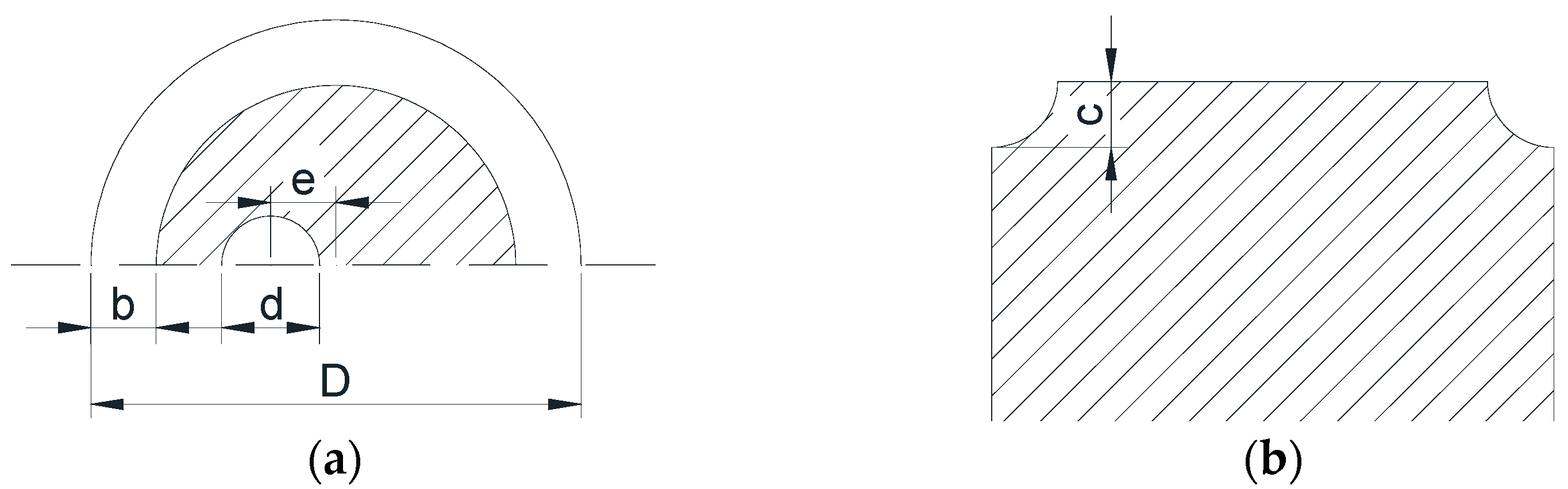
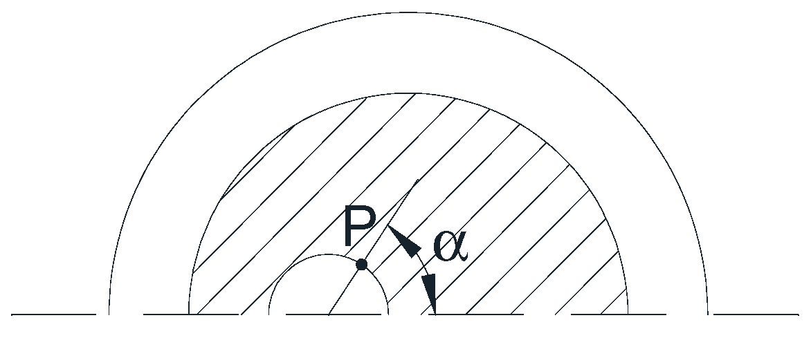
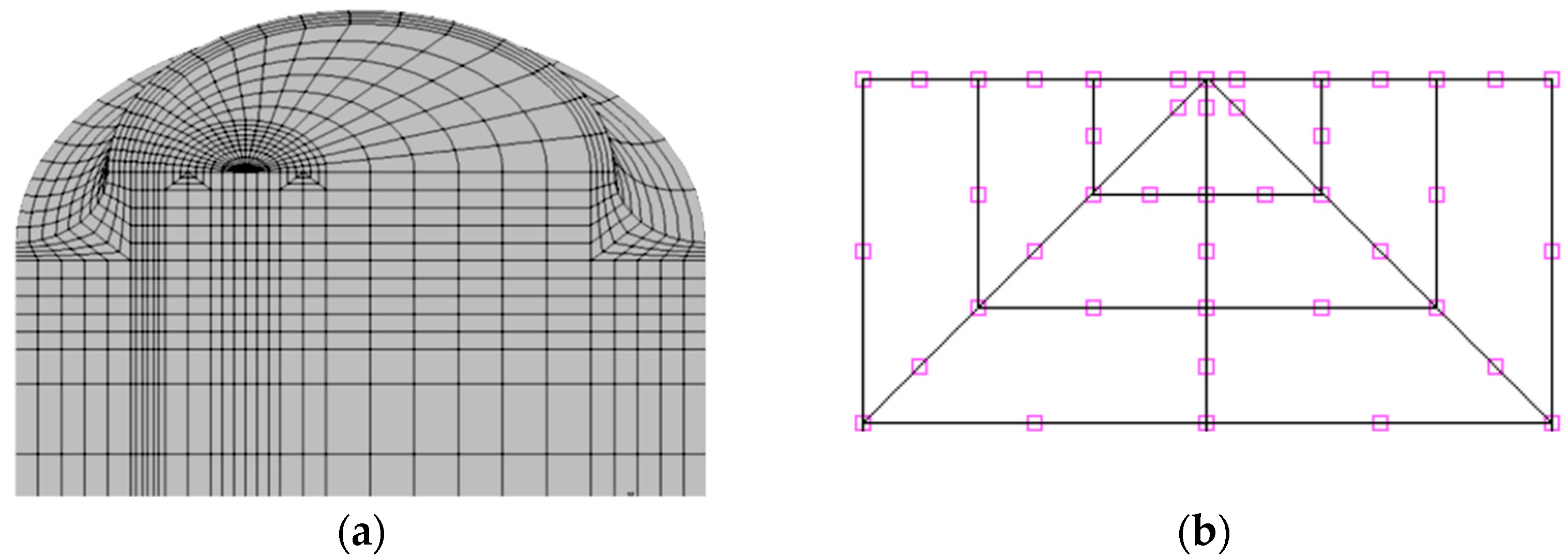
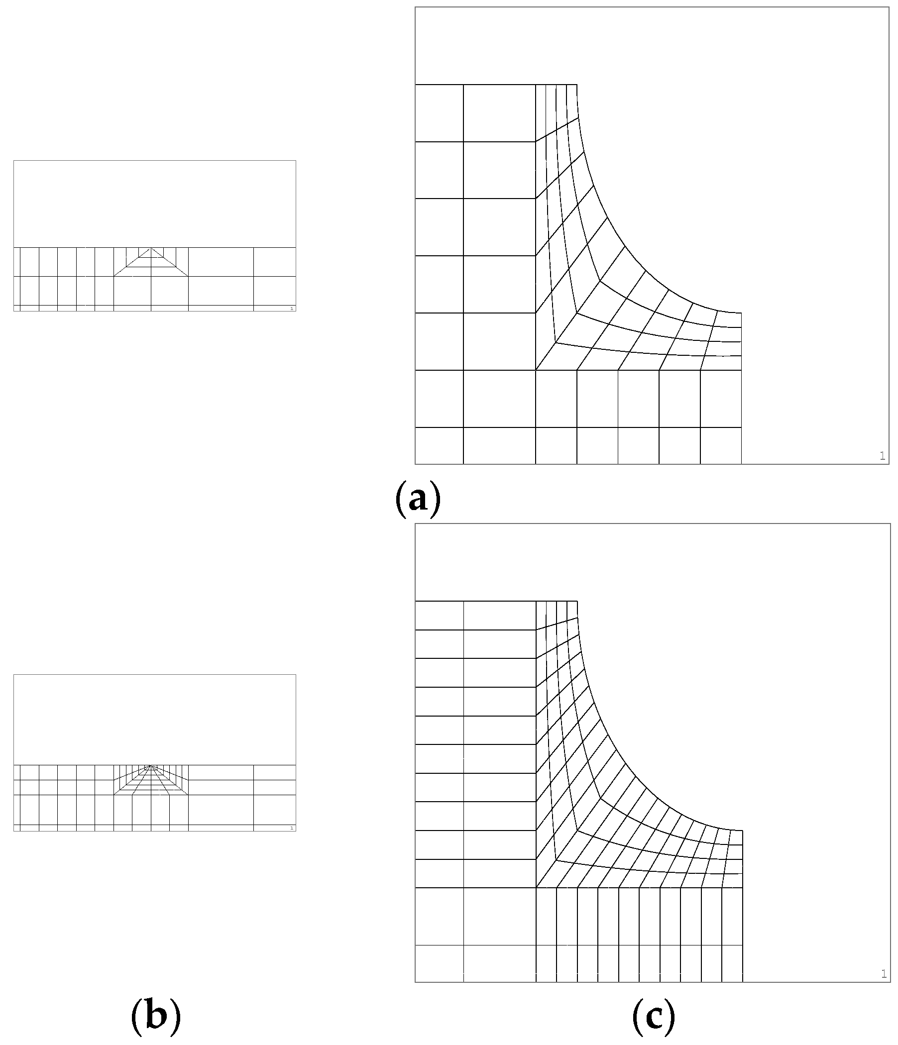
2. Numerical Procedure
3. Numerical Results and Discussion
3.1. Stress Intensity Factors for the Symmetrical Case
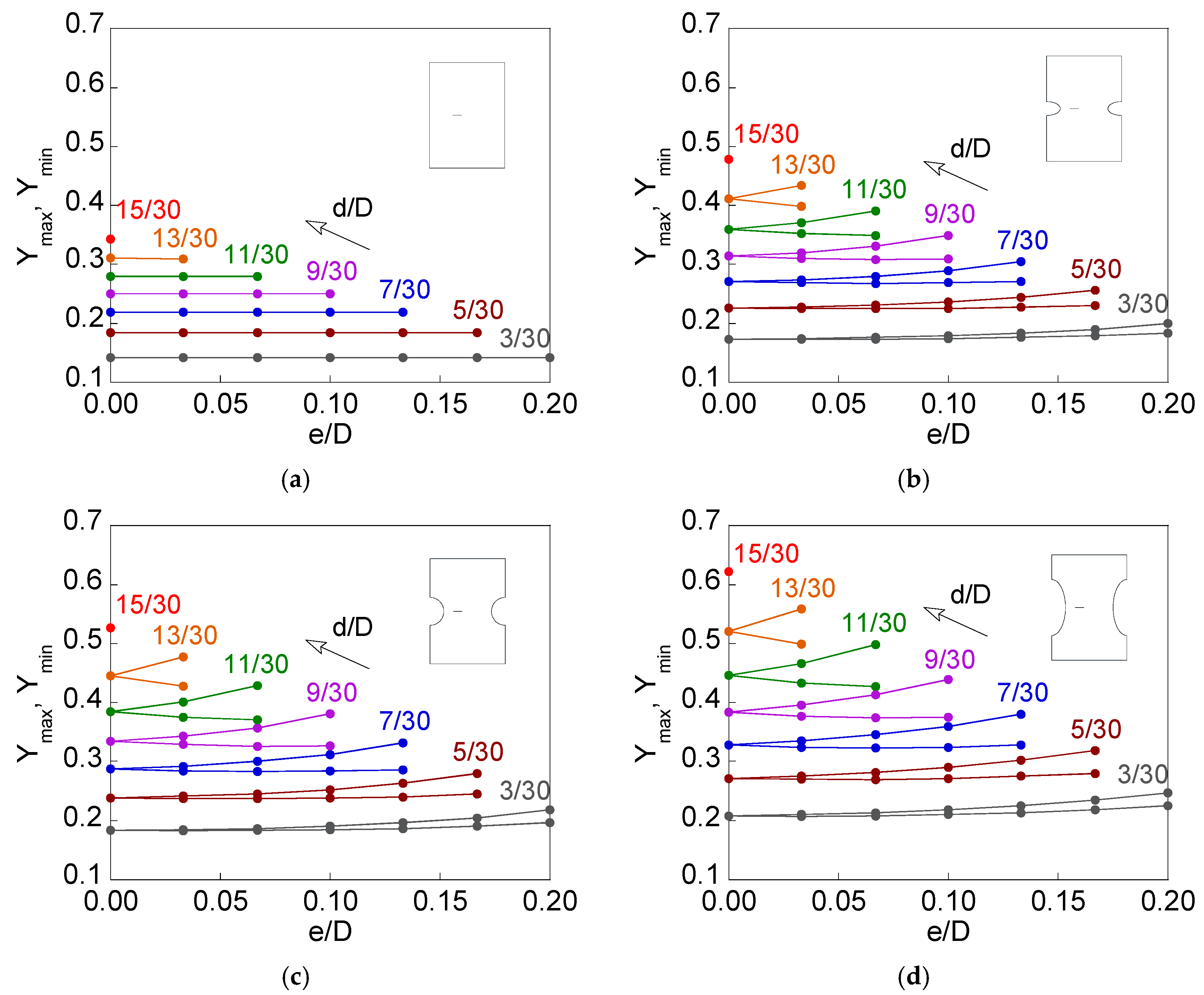
3.2. Stress Intensity Factors for Eccentric Circular Inner Cracks
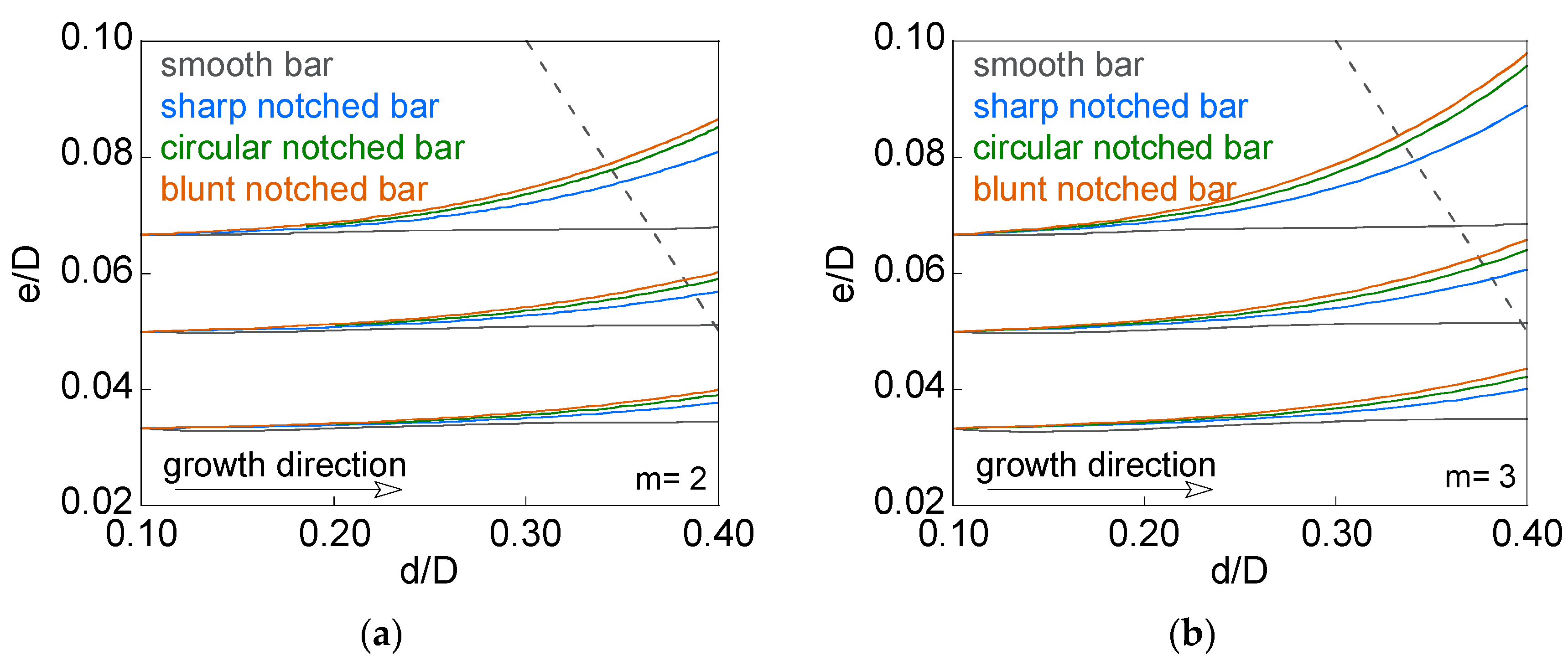
3.3. Eccentric Circular Inner Crack Propagation
4. Conclusions
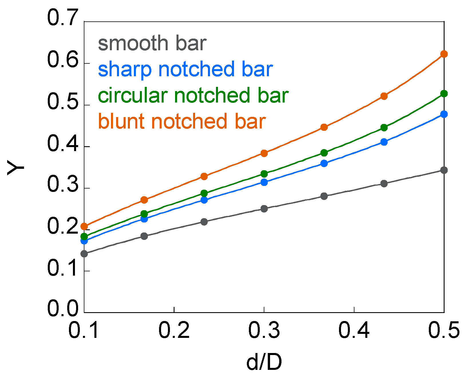
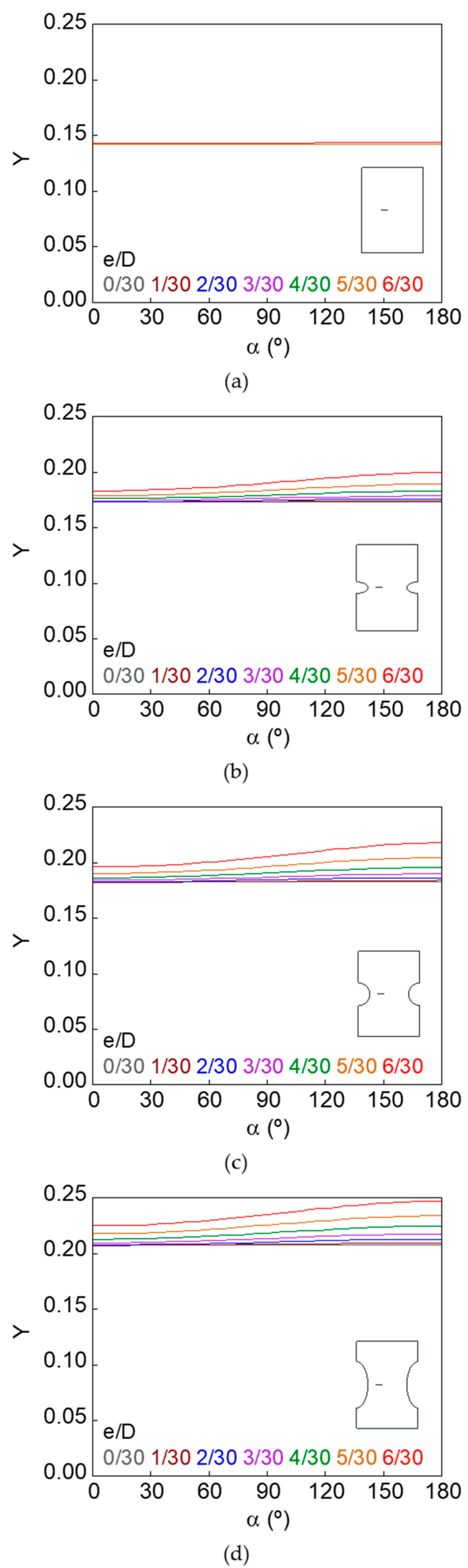
- The presence of the notch in the cracked bar produces an increase in the stress intensity factor (SIF) value.
- For elliptical notches of equal depth, the increase of the axial semi-axis raises the SIF for the same crack configuration.
- The cause of this phenomenon can be attributed to the constraint loss on the crack front. This fact also favours the specimen bending due to the crack eccentricity.
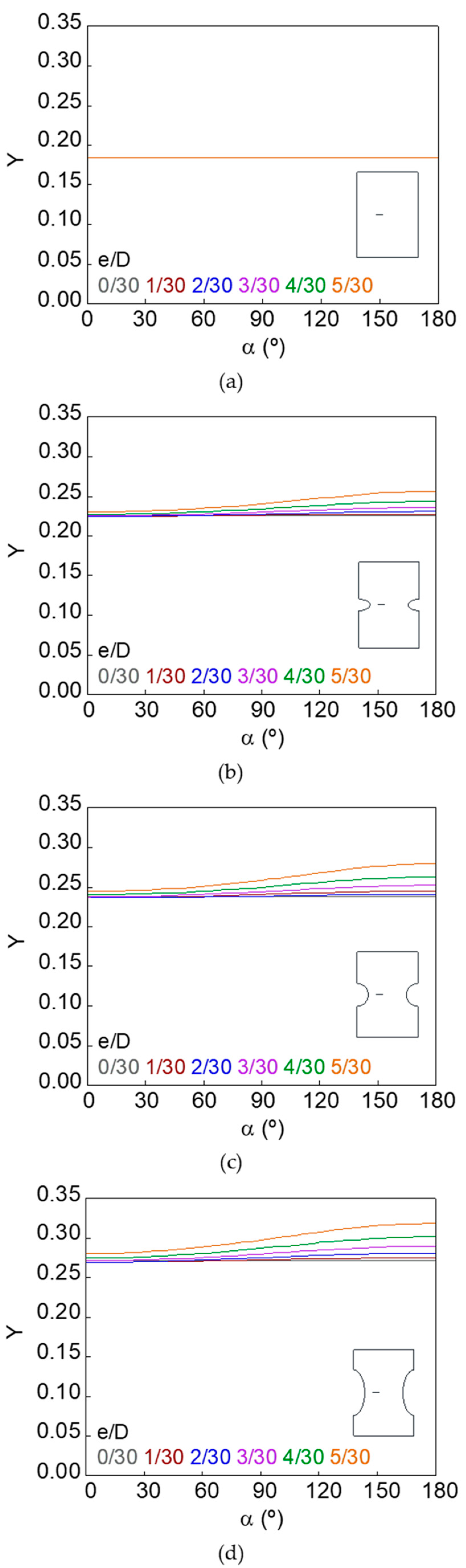
- The maximum SIF increases with the relative crack eccentricity, while the minimum SIF decreases for small eccentricities and increases for high eccentricities.
- The difference between the SIF values in the crack front increases with the relative crack diameter, the relative crack eccentricity, and the notch axial semi-axis.
- During fatigue propagation of small eccentric cracks, there is a gradual increase in eccentricity, this effect being more visible with increasing initial relative crack eccentricity, notch axial semi-axis, and Paris exponent.
Author Contributions
Funding
Institutional Review Board Statement
Informed Consent Statement
Data Availability Statement
Conflicts of Interest
References
- Brimacombe, J.K.; Sorimachi, K. Crack formation in the continuous casting of steel. Metall. Trans. B 1977, 8, 489–505. [Google Scholar] [CrossRef]
- Ogawa, T.; Stanzl-Tschegg, S.E.; Schönbauer, B.M. A fracture mechanics approach to interior fatigue crack growth in the very high cycle regime. Eng. Fract. Mech. 2014, 115, 241–254. [Google Scholar] [CrossRef]
- Nehila, A.; Li, W.; Zhao, H. Interior failure mechanism and life prediction of surface treated 17Cr-Ni steel under high and very high cycle fatigue. Fatigue Fract. Eng. Mater. Struct. 2018, 41, 1318–1329. [Google Scholar] [CrossRef]
- Chen, Y.; Peng, X.; Kong, L.; Dong, G.; Remani, A.; Leach, R. Defect inspection technologies for additive manufacturing. Int. J. Extrem. Manuf. 2021, 3, 022002. [Google Scholar] [CrossRef]
- Tanaka, K.; Akiniwa, Y. Fatigue crack propagation behaviour derived from S-N data in very high cycle regime. Fatigue Fract. Eng. Mech. Mater. Struct. 2002, 25, 775–784. [Google Scholar] [CrossRef]
- Qin, S.; Zhang, C.; Zhang, B.; Ma, H.; Zhao, M. Effect of carburizing process on high cycle fatigue behavior of 18CrNiMo7-6 steel. J. Mater. Res. Technol. 2022, 16, 1136–1149. [Google Scholar] [CrossRef]
- Nishioka, T.; Atluri, S.N. Analytical solution for embedded elliptical cracks, and finite element alternating method for elliptical surface cracks, subjected to arbitrary loadings. Eng. Fract. Mech. 1983, 17, 247–268. [Google Scholar] [CrossRef]
- Tada, H.; Paris, P.C.; Irwin, G.R. The Stress Analysis of Cracks Handbook, 3rd ed.; ASME Press: New York, NY, USA, 1985. [Google Scholar]
- Murakami, Y. Stress Intensity Factors Handbook; Pergamon Press: Oxford, UK, 1987. [Google Scholar]
- Eshraghi, I.; Soltani, N. Stress intensity factor calculation for internal circumferential cracks in functionally graded cylinders using the weight function approach. Eng. Fract. Mech. 2015, 134, 1–19. [Google Scholar] [CrossRef]
- Shariati, M.; Rokhi, M.M.; Rayegan, H. Investigation of stress intensity factor for internal cracks in FG cylinders under static and dynamic loading. Frat. Integrità Strutt. 2017, 39, 166–180. [Google Scholar] [CrossRef]
- Rojo, F.J. Aplicación de la Mecánica de Fractura a la Rotura Frágil de Fibras de Sémola. Ph.D. Thesis, Universidad Politécnica de Madrid, Madrid, Spain, 2003. (In Spanish). [Google Scholar]
- Guinea, G.V.; Rojo, F.J.; Elices, M. Stress intensity factors for internal circular cracks in fibers under tensile loading. Eng. Fract. Mech. 2004, 71, 365–377. [Google Scholar] [CrossRef]
- Toribio, J.; Matos, J.C.; González, B. Stress intensity factor for an eccentric circular inner crack in a round bar subjected to tensile loading. Procedia Struct. Integr. 2020, 28, 2382–2385. [Google Scholar] [CrossRef]
- Toribio, J.; González, B.; Matos, J.C. Review and synthesis of stress intensity factor (SIF) solutions for circular inner cracks in round bars under tension loading. Procedia Struct. Integr. 2022, 37, 995–1000. [Google Scholar] [CrossRef]
- Chen, X.; Chan, A.H.C. Modelling impact fracture and fragmentation of laminated glass using the combined finite-discrete element method. Int. J. Impact Eng. 2018, 112, 15–29. [Google Scholar] [CrossRef]
- Chen, X.; Luo, T.; Ooi, E.T.; Ooi, E.H.; Song, C. A quadtree-polygon-based scaled boundary finite element method for crack propagation modeling in functionally graded materials. Theor. Appl. Fract. Mech. 2018, 94, 120–133. [Google Scholar] [CrossRef]
- Jin, H.; Yu, S. Study on corrosion-induced cracks for the concrete with transverse cracks using an improved CDM-XFEM. Constr. Build. Mater. 2022, 318, 126173. [Google Scholar] [CrossRef]
- Lin, X.B.; Smith, R.A. Fatigue growth simulation for cracks in notched and unnotched round bars. Int. J. Mech. Sci. 1998, 40, 405–419. [Google Scholar] [CrossRef]
- Guo, W.; Shen, H.; Li, H. Stress intensity factors for elliptical surface cracks in round bars with different stress concentration coefficient. Int. J. Fatigue 2003, 25, 733–741. [Google Scholar] [CrossRef]
- Carpinteri, A.; Ronchei, C.; Vantadori, S. Stress intensity factors and fatigue growth of surface cracks in notched shells and round bars: Two decades of research work. Fatigue Fract. Eng. Mater. Struct. 2013, 36, 1164–1177. [Google Scholar] [CrossRef]
- Yu, Y.; Pei, X.; Wang, P.; Dong, P.; Fang, H. A Structural stress approach accounting for notch effects on fatigue propagation life: Part I theory. Int. J. Fatigue 2022, 159, 106793. [Google Scholar] [CrossRef]
- Zhaokuang, C.; Jinjiang, Y.; Xiaofeng, S.; Hengrong, G.; Zhuangqi, H. High cycle fatigue behavior of a directionally solidified Ni-base superalloy DZ951. Mater. Sci. Eng. A 2008, 496, 355–361. [Google Scholar] [CrossRef]
- Wang, H.; Li, H.; Tang, L.; Zhu, C.; Ren, X.; Qiao, Y.; Feng, G. Fracture of brittle solid with an internal penny-shaped crack: Semi-circular bending test and numerical simulation. Eng. Fract. Mech. 2022, 262, 108260. [Google Scholar] [CrossRef]
- Paris, P.; Erdogan, F. A critical analysis of crack propagation laws. J. Basic Eng. 1963, 85, 528–534. [Google Scholar] [CrossRef]
- Busari, Y.O.; Manurung, Y.H.P.; Leitner, M.; Shuaib-Babata, Y.L.; Mat, M.F.; Ibrahim, H.K.; Simunek, D.; Sulaiman, M.S. Numerical evaluation of fatigue crack growth of structural steels using energy release rate with VCCT. Appl. Sci. 2022, 12, 2641. [Google Scholar] [CrossRef]
- Nguyen, H.Q.; Gallimard, L.; Bathias, C. Numerical simulation of fish-eye fatigue crack growth in very high cycle fatigue. Eng. Fract. Mech. 2015, 135, 81–93. [Google Scholar] [CrossRef]
- Irwin, G.R. Analysis of stresses and strain near the end of a crack traversing a plate. J. Appl. Mech. 1957, 24, 361–364. [Google Scholar] [CrossRef]
- Toribio, J.; Matos, J.C.; González, B. Notch effect on the stress intensity factor in tension-loaded circumferentially cracked bars. Eng. Fract. Mech. 2018, 202, 436–444. [Google Scholar] [CrossRef]


| d (mm) | e (mm) |
|---|---|
| 0.3 | 0; 0.1; 0.2; 0.3; 0.4; 0.5; 0.6 |
| 0.5 | 0; 0.1; 0.2; 0.3; 0.4; 0.5 |
| 0.7 | 0; 0.1; 0.2; 0.3; 0.4 |
| 0.9 | 0; 0.1; 0.2; 0.3 |
| 1.1 | 0; 0.1; 0.2 |
| 1.3 | 0; 0.1 |
| 1.5 | 0 |
| Notch and Crack Geometry | Number of Elements | ||||
|---|---|---|---|---|---|
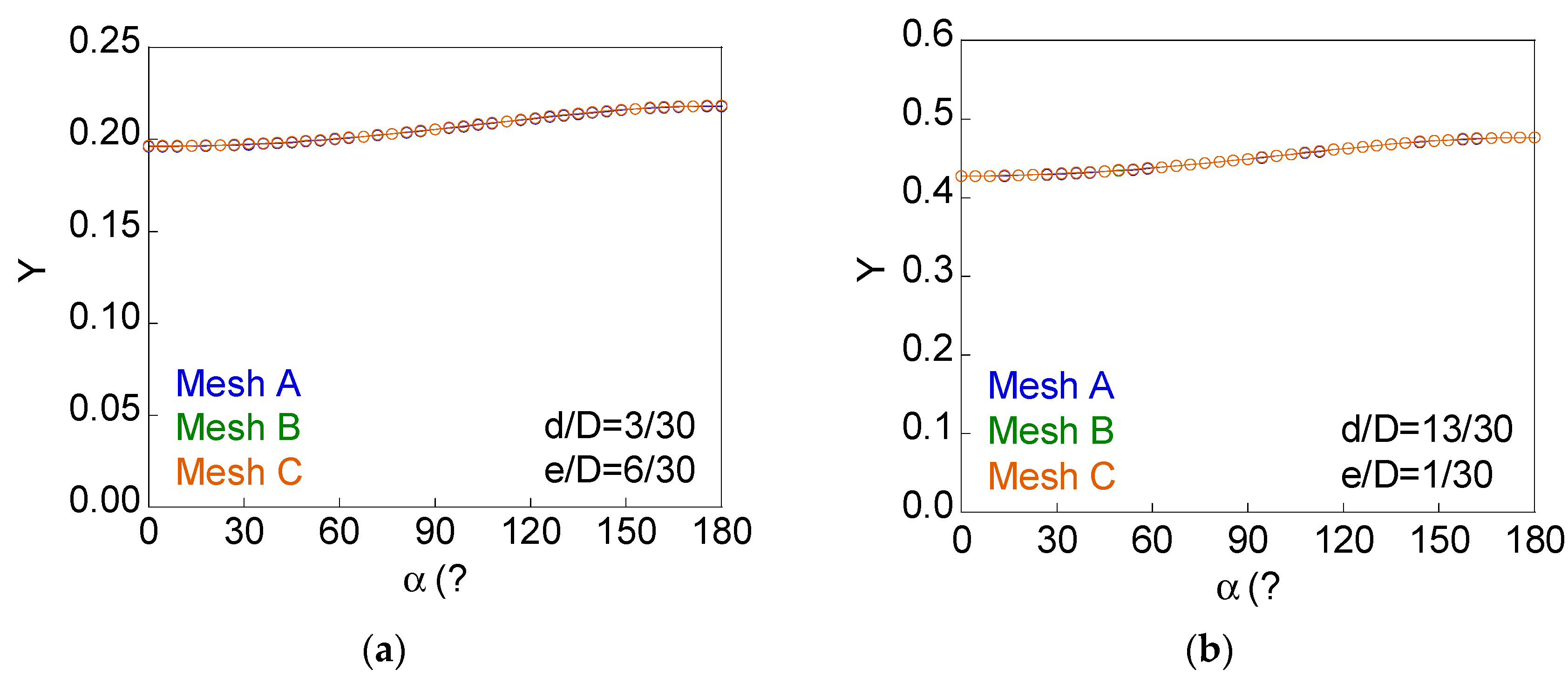
| c/b | d/D | e/D | Mesh A | Mesh B | Mesh C |
| 1 | 3/30 | 6/30 | 4400 | 5840 | 8320 |
| 13/30 | 1/30 | 5700 | 7240 | 10,120 | |
Publisher’s Note: MDPI stays neutral with regard to jurisdictional claims in published maps and institutional affiliations. |
© 2022 by the authors. Licensee MDPI, Basel, Switzerland. This article is an open access article distributed under the terms and conditions of the Creative Commons Attribution (CC BY) license (https://creativecommons.org/licenses/by/4.0/).
Share and Cite
Toribio, J.; González, B.; Matos, J.-C.; González, I. Notch Effects on the Stress Intensity Factor and on the Fatigue Crack Path for Eccentric Circular Internal Cracks in Elliptically Notched Round Bars under Tensile Loading. Materials 2022, 15, 9091. https://doi.org/10.3390/ma15249091
Toribio J, González B, Matos J-C, González I. Notch Effects on the Stress Intensity Factor and on the Fatigue Crack Path for Eccentric Circular Internal Cracks in Elliptically Notched Round Bars under Tensile Loading. Materials. 2022; 15(24):9091. https://doi.org/10.3390/ma15249091
Chicago/Turabian StyleToribio, Jesús, Beatriz González, Juan-Carlos Matos, and Iván González. 2022. "Notch Effects on the Stress Intensity Factor and on the Fatigue Crack Path for Eccentric Circular Internal Cracks in Elliptically Notched Round Bars under Tensile Loading" Materials 15, no. 24: 9091. https://doi.org/10.3390/ma15249091
APA StyleToribio, J., González, B., Matos, J.-C., & González, I. (2022). Notch Effects on the Stress Intensity Factor and on the Fatigue Crack Path for Eccentric Circular Internal Cracks in Elliptically Notched Round Bars under Tensile Loading. Materials, 15(24), 9091. https://doi.org/10.3390/ma15249091