
Characterization of Carbide Precipitation during Tempering for Quenched Dievar Steel


Abstract
:1. Introduction
2. Materials and Experimental Procedures
3. Results
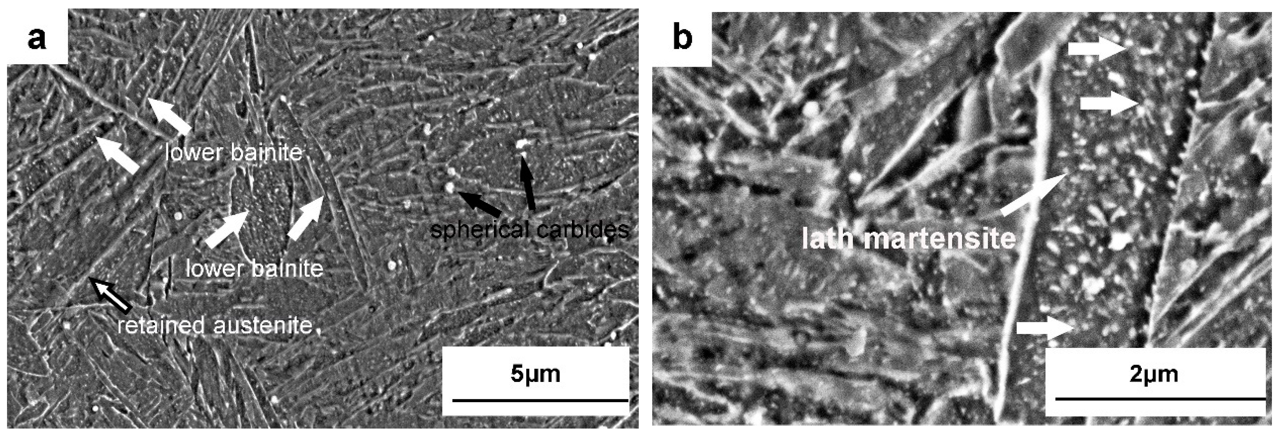
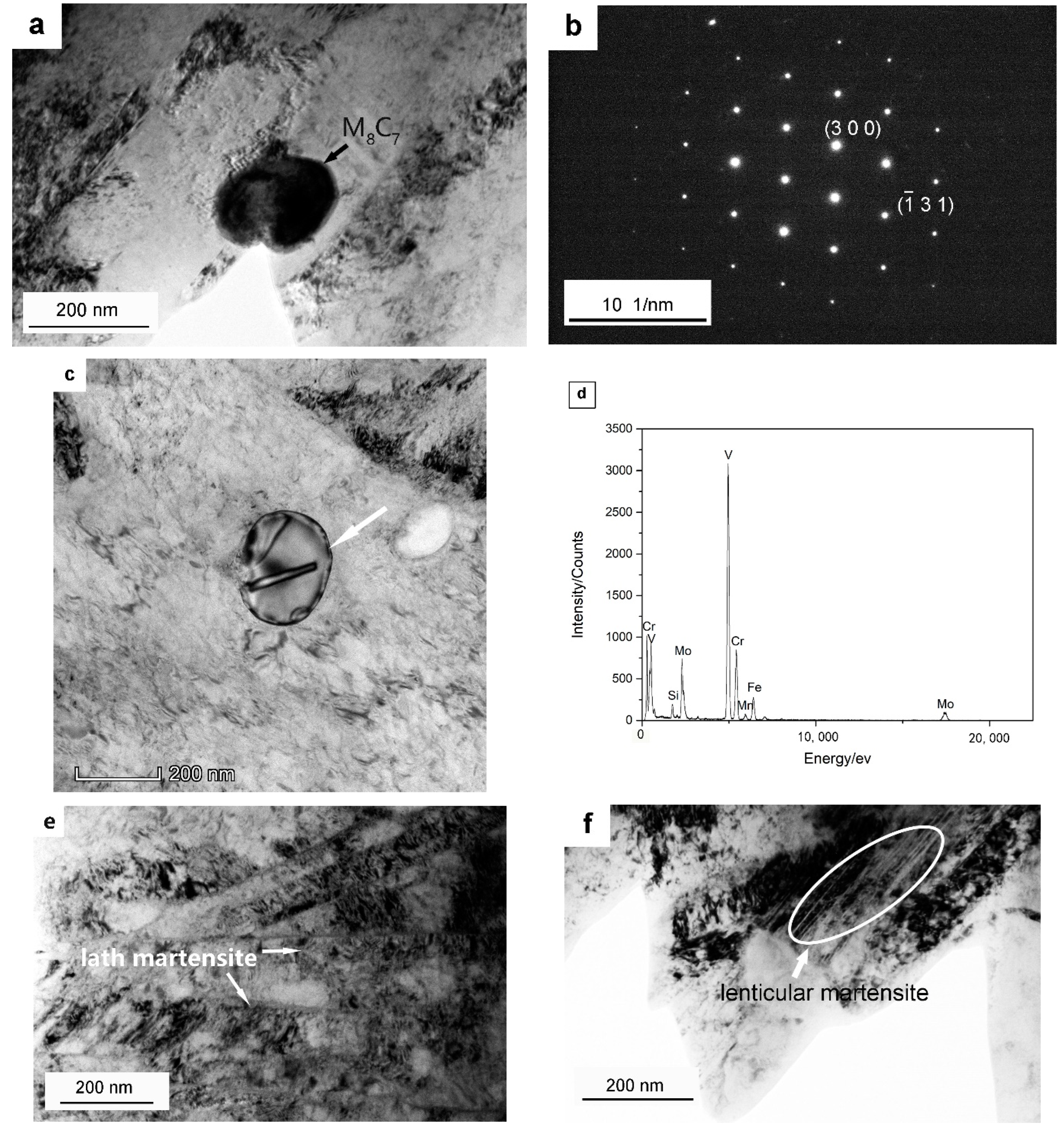
3.1. Microstructures of Quenched Dievar Steel
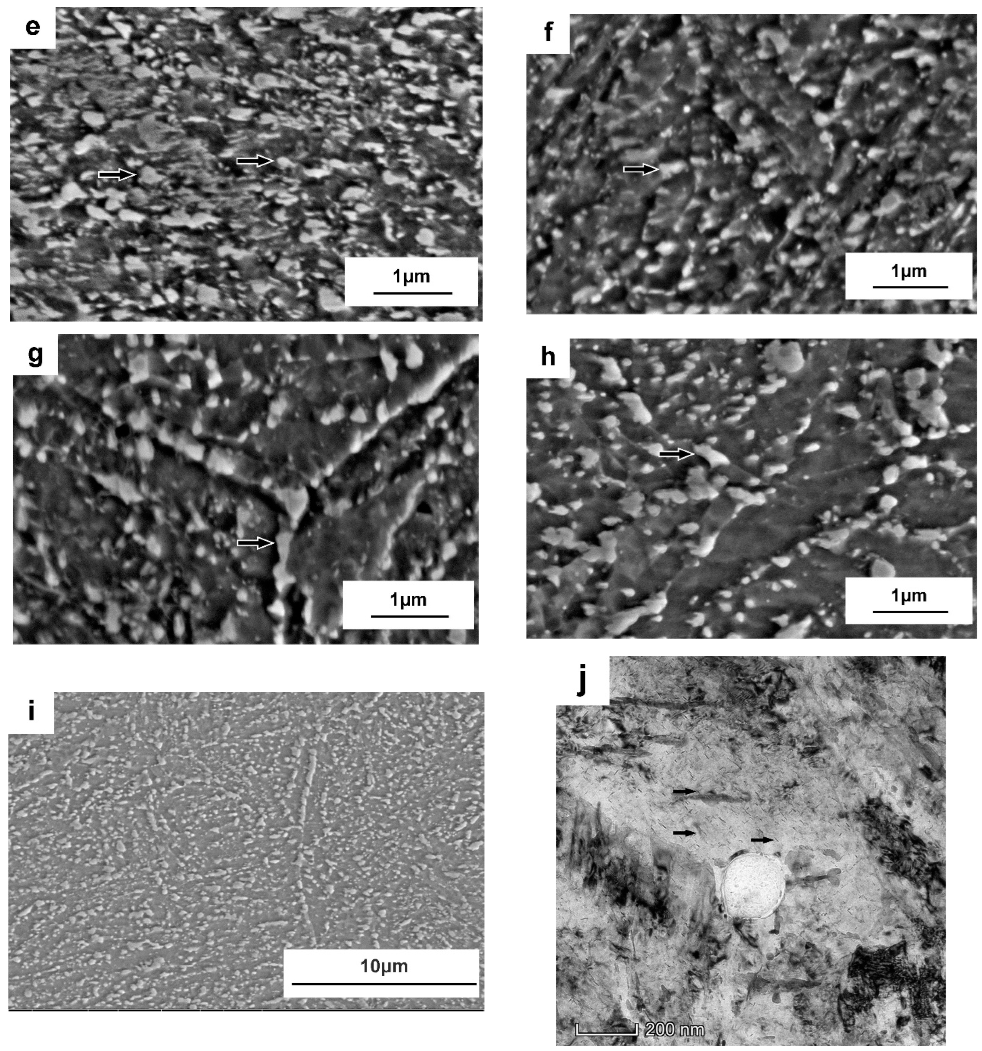
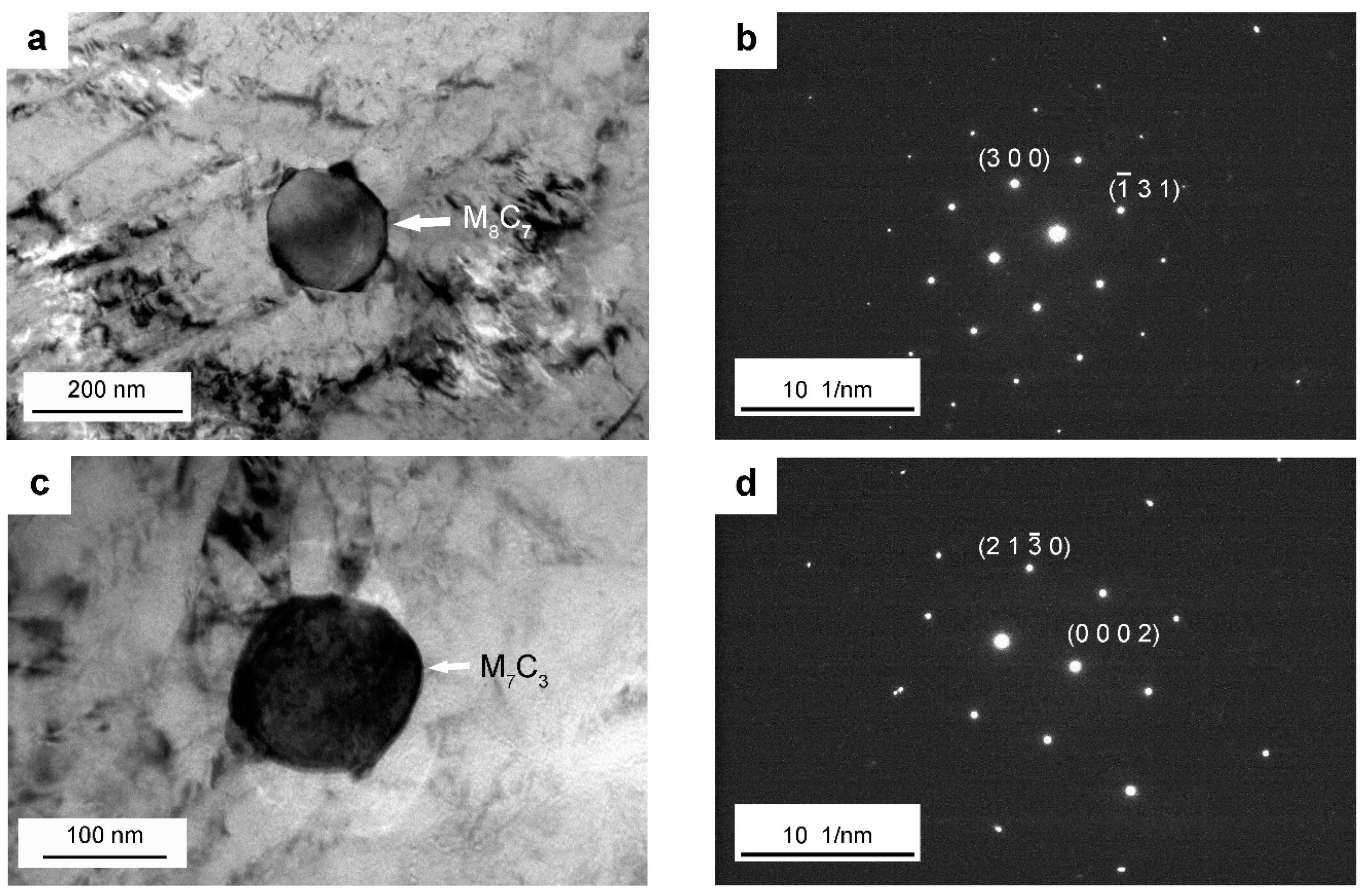
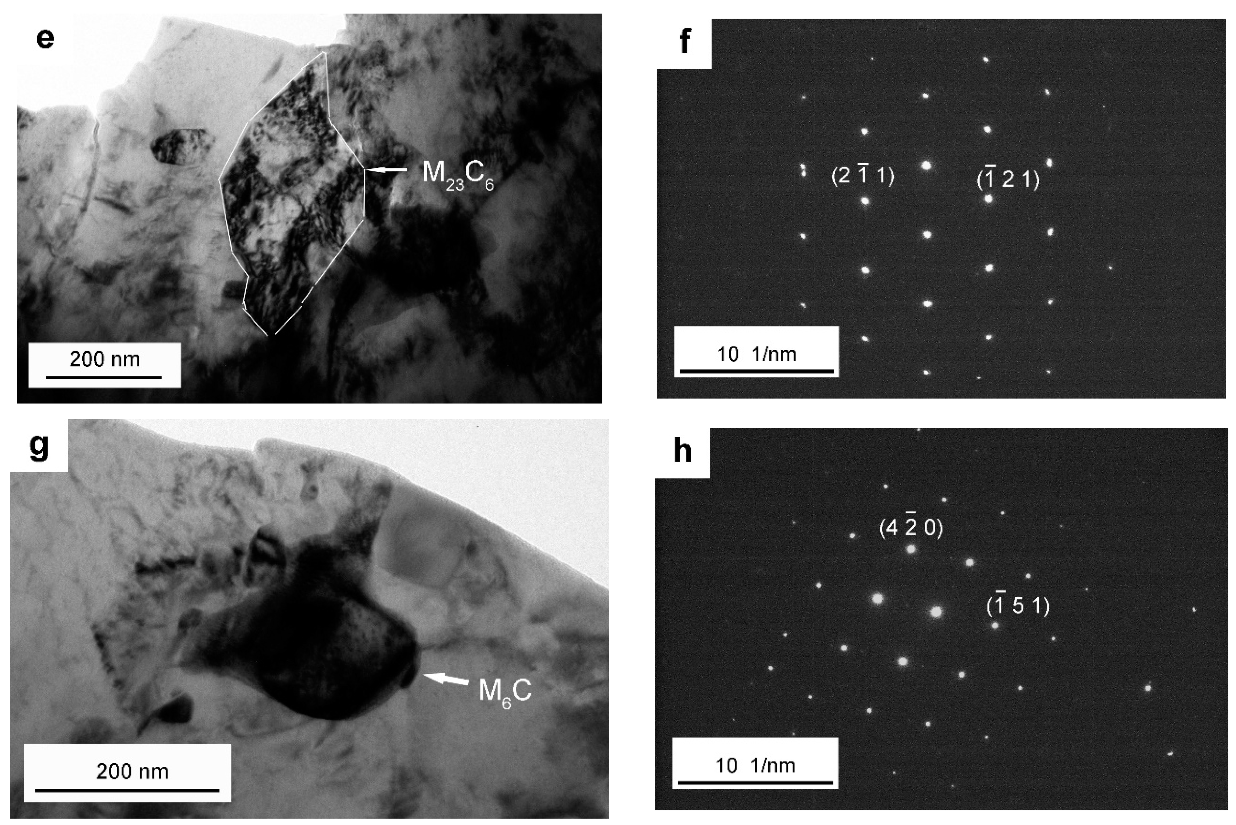
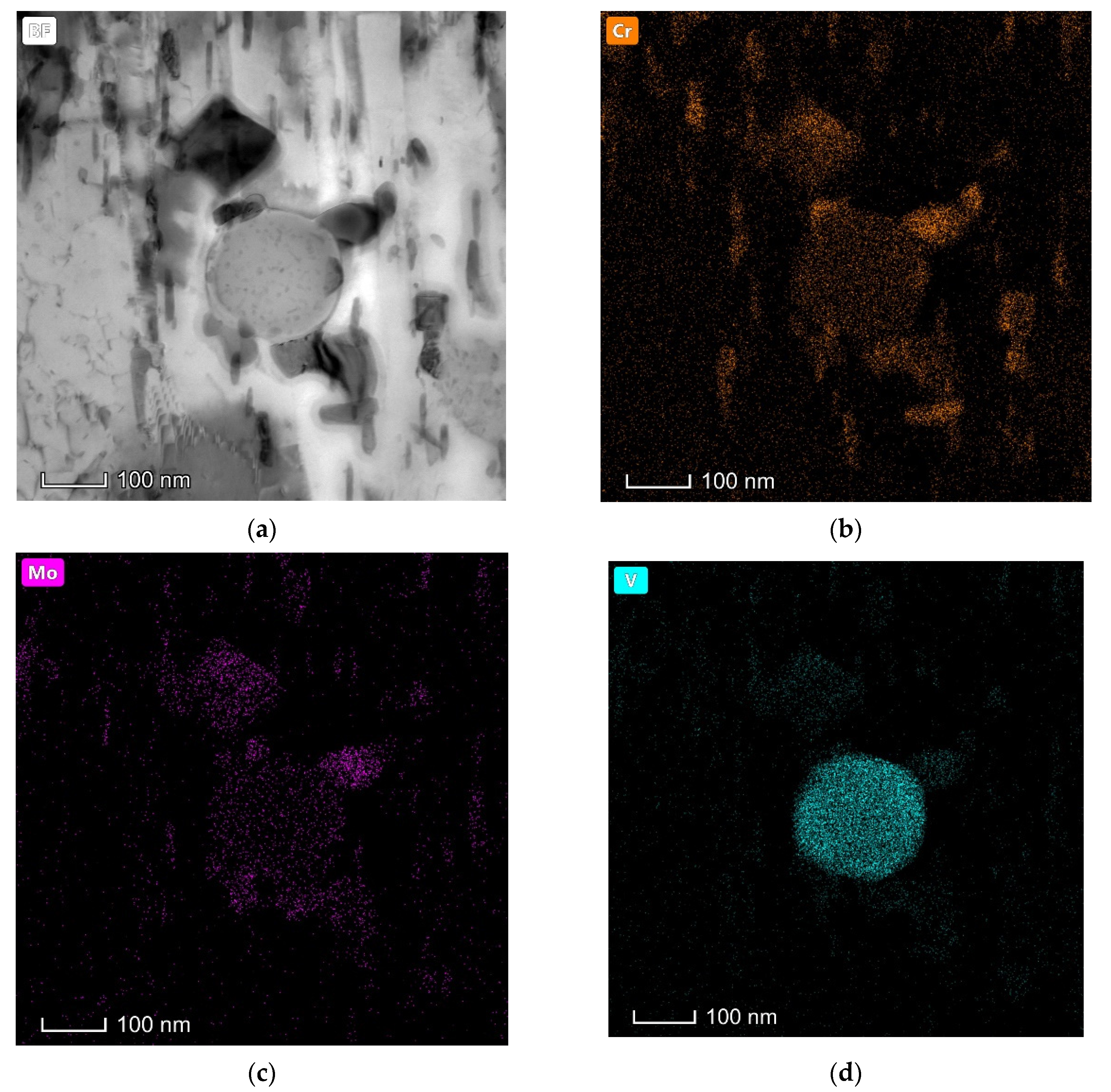
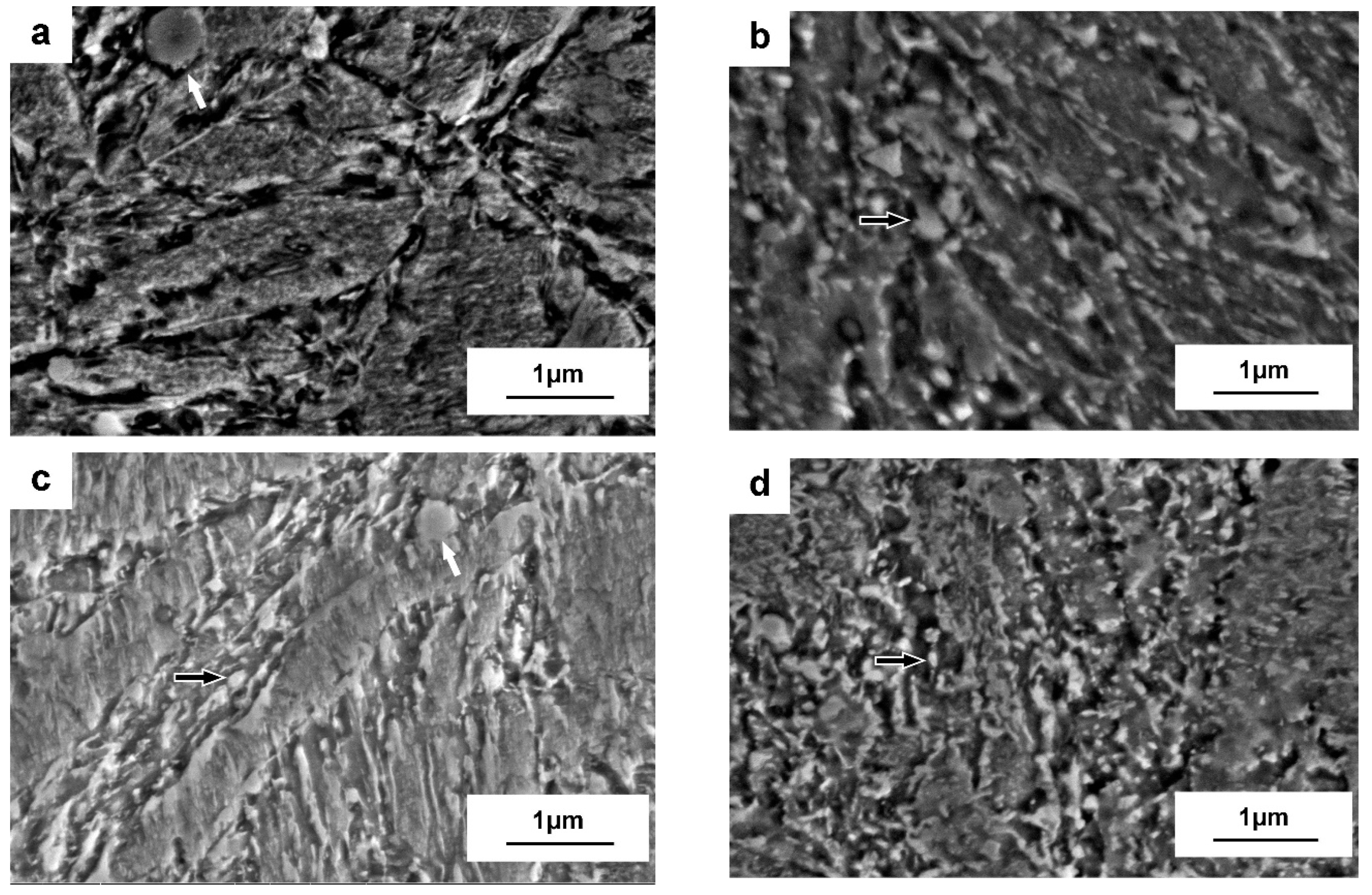
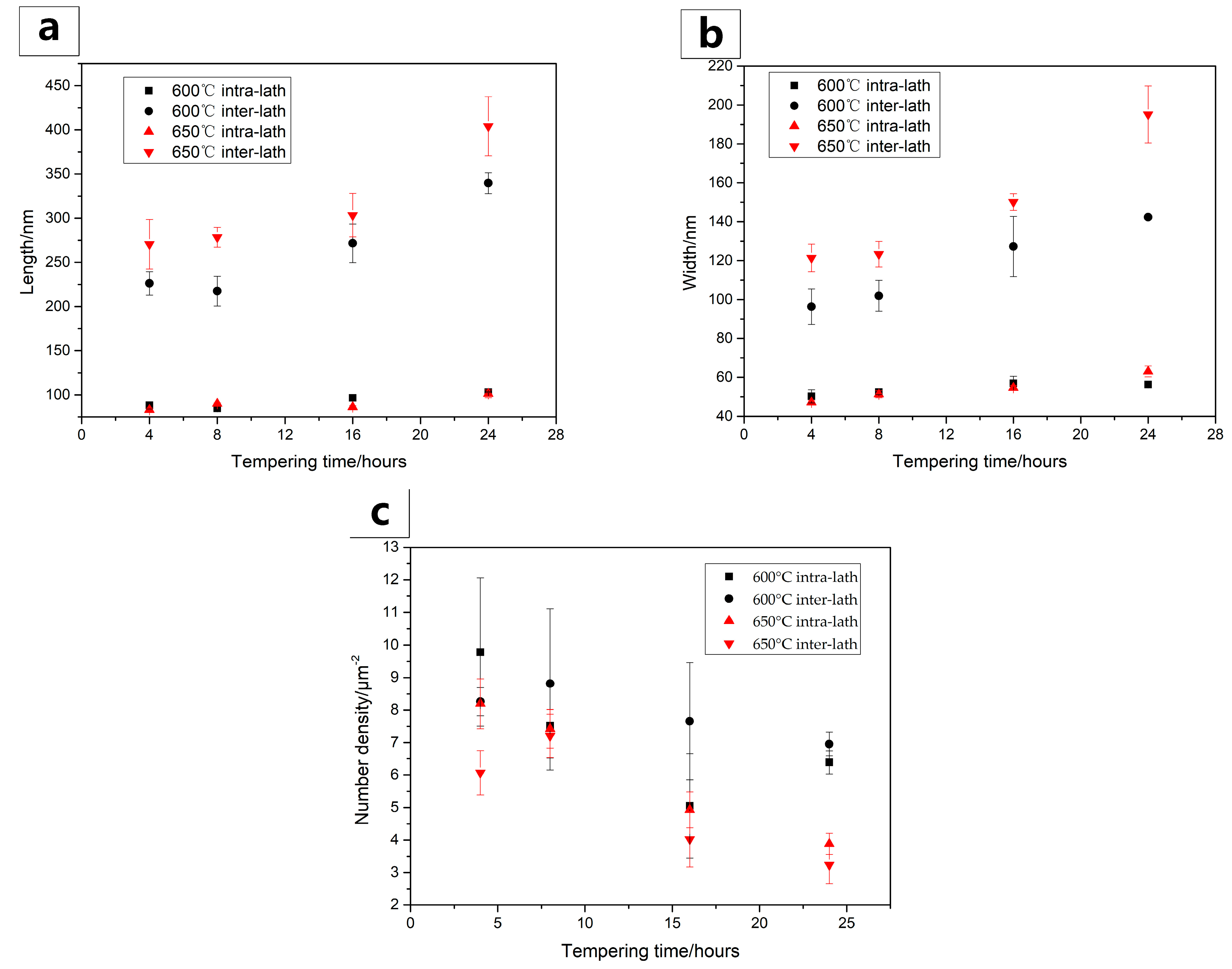
3.2. Microstructure Evolutions during Tempering
4. Discussion
5. Conclusions
Author Contributions
Funding
Conflicts of Interest
References
- Jiménez, H.; Devia, D.M.; Benavides, V.; Devia, A.; Arango, A.C.; Arango, P.J.; Velez, J.M. Thermal protection of H13 steel by growth of (TiAl)N films by PAPVD pulsed arc technique. Mater. Charact. 2008, 59, 1070–1077. [Google Scholar] [CrossRef]
- Zhao, Y.; Liang, Y.; Zhou, W.; QIN, Q.D.; Jiang, Q.C. Effect of current pulse on the thermal fatiguebehavior of cast hot work die steel. ISIJ Int. 2005, 45, 410–412. [Google Scholar] [CrossRef]
- Yan, G.; Huang, X.; Wang, Y.; Chu, Z.M.; Jin, K.; Qin, X.G.; Yang, M. Effects of heat treatment on mechanical properties of H13 steel. Metal. Sci. Heat. Treat. 2010, 52, 393–395. [Google Scholar]
- Silva, A.K.D.; Leyson, G.; Kuzmina, M.; Ponge, D.; Herbig, M.; Sandlöbes, S.; Gault, B.; Neugebauer, J.; Raabe, D. Confined chemical and structural states at dislocations in Fe-9wt% Mn steels: A correlative TEM-atom probe study combined with multiscale modelling. Acta Mater. 2017, 124, 305–315. [Google Scholar] [CrossRef]
- Gronostajski, Z.; Kaszuba, M.; Polak, S.; Zwierzchowski, M.; Niechajowicz, A.; Hawryluk, M. The failure mechanisms of hot forging dies. Mater. Sci. Eng. A-Struct. Mater. Prop. Microstruct. Process. 2016, 657, 147–160. [Google Scholar] [CrossRef]
- Gopalsamy, B.M.; Mondal, B.; Ghosh, S.; Arntz, K.; Klocke, F. Experimental investigations while hard machining of DIEVAR tool steel (50 HRC). Int. J. Adv. Manuf. Technol. 2010, 51, 853–869. [Google Scholar] [CrossRef]
- Kozeschnik, E.; Bhadeshia, H.K.D.H. Influence of silicon on cementite precipitation in steels. Mater. Sci. Technol. 2008, 24, 343–347. [Google Scholar] [CrossRef]
- Zhang, Z.; Delagnes, D.; Bernhart, G. Microstructure evolution of hot-work tool steels during tempering and definition of a kinetic law based on hardness measurements. Mater. Sci. Eng. A-Struct. Mater. Prop. Microstruct. Process. 2004, 380, 222–230. [Google Scholar] [CrossRef]
- Mellouli, D.; Haddar, N.; Koster, A.; Ayedi, H.F. Thermal fatigue failure of brass die-casting dies. Eng. Fail. Anal. 2012, 20, 137–146. [Google Scholar] [CrossRef]
- Markežič, R.; Naglič, I.; Mole, N.; Šturm, R. Experimental and numerical analysis of failures on a die insert for high pressure die casting. Eng. Fail. Anal. 2019, 95, 171–180. [Google Scholar] [CrossRef]
- Mesquita, R.A.; Barbosa, C.A.; Machado, A.R. Heat Treatment of Tool Steels. Reference Module in Materials Science and Materials Engineering. Compr. Mater. Finish. 2017, 2, 214–245. [Google Scholar]
- Jagota, V.; Sharma, R.K.; Sehgal, R. Impact of austenitizing temperature on the wear behaviour of AISI H13 steel. Proc. Inst. Mech. Eng. Part J. 2021, 235, 564–574. [Google Scholar] [CrossRef]
- Naimi, S.; Hosseini, S.M. Tool steels in die-casting utilization and increased mold life. Adv. Mech. Eng. 2014, 7, 1–10. [Google Scholar] [CrossRef]
- Jesperson, H. Influence of the heat treatment on the toughness of some hot-work tool steel grades. La Metallurgia Italiana 2013, XCIII(2), 29–37. [Google Scholar]
- Sjöström, J.; Bergström, J. Thermal fatigue testing of chromium martensitic hot-work tool steel after different austenitizing treatments. J. Mater. Process. Technol. 2004, 153–154, 1089–1096. [Google Scholar] [CrossRef]
- Zhou, J.; Ma, D.; Chi, H.; Chen, Z.Z.; Li, X.Y. Microstructure and properties of hot working die steel H13MOD. Iron. Steel. Res. Int. 2013, 20, 117–125. [Google Scholar] [CrossRef]
- Qi, Y.F.; Li, J.; Shi, C.B.; Zhang, Y.; Zhu, Q.T.; Wang, H. Effect of directional solidification of electroslag remelting on the microstructure and primary carbides in an austenitic hot-work die steel. J. Mater. Process. Technol. 2017, 249, 32–38. [Google Scholar] [CrossRef]
- Eser, A.; Broeckmann, C.; Simsir, C. Multiscale modeling of tempering of AISI H13 hot-work tool steel—Part 1: Prediction of microstructure evolution and coupling with mechanical properties. Comput. Mater. Sci. 2016, 113, 280–291. [Google Scholar] [CrossRef]
- Zhu, J.; Zhang, Z.; Xie, J. Improving strength and ductility of H13 die steel by pre-tempering treatment and its mechanism. Mater. Sci. Eng. A Struct. Mater. Prop Microstruct. Process. 2019, 752, 101–114. [Google Scholar] [CrossRef]
- Ning, A.; Mao, W.; Chen, X.; Guo, H.; Guo, J. Precipitation behavior of carbides in H13 Hot Work Die steel and its strengthening during Tempering. Metals 2017, 7, 70. [Google Scholar] [CrossRef]
- Inoue, A.; Masumoto, T. Carbide reactions (M3C → M7C3 → M23C6 → M6C) during tempering of rapidly solidified high carbon Cr-W and Cr-Mo steels. Metall. Mater. Trans. A-Phys. Metall. Mater. Sci. 1980, 11, 739–747. [Google Scholar] [CrossRef]
- Ule, B.; Vodovpiec, F.; Pristavec, M.; Greovnik, F. Temper embrittlement of hot working die steel. Metal. Sci. Tech.-Lond. 1991, 12, 43–46. [Google Scholar]
- Chen, C.; Yan, K.; Qin, L.B.; Zhang, M.; Wang, X.N.; Zou, T.; Hu, Z.R. Effect of heat treatment on microstructure and mechanical properties of laser additively manufactured AISI H13 tool steel. J. Mater. Eng. Perform. 2017, 11, 5577–5589. [Google Scholar] [CrossRef]
- Ju, Y.; Goodall, A.; Strangwood, M.; Davis, C. Characterisation of precipitation and carbide coarsening in low carbon low alloy Q&T steels during the early stages of tempering. Mater. Sci. Eng. A Struct. Mater. Prop. Microstruct. Process. 2018, 738, 174–189. [Google Scholar]
- Wang, J.; Xu, Z.; Lu, X. Effect of the Quenching and Tempering Temperatures on the Microstructure and Mechanical Properties of H13 Steel. Mater. Eng. Perform. 2020, 29, 1849–1859. [Google Scholar] [CrossRef]
- Qi, J.; Li, Y.; Zhou, H. Retained austenite, twin substructure and self tempering carbides in quenched low carbon lath martensite. Acta Mater. 1984, 1, 44–53. [Google Scholar]
- Katancik, M.; Mirzababaei, S.; Ghayoor, M.; Pasebani, S. Selective laser melting and tempering of H13 tool steel for rapid tooling applications. J. Alloys Compd. 2020, 849, 156319. [Google Scholar] [CrossRef]
- Shinde, T. Influence of carbide particle size on the wear performance of cryogenically treated H13 die steel. Surf. Eng. 2020, 10, 1–9. [Google Scholar] [CrossRef]
- Ferrari, M.T.C.; Andersson, J.; Kvarnström, M. Influence of lowered austenitisation temperature during hardening on tempering resistance of modified H13 tool steel (Uddeholm Dievar). Int. Heat Treat. Surf. Eng. 2013, 7, 129–132. [Google Scholar] [CrossRef]
- Chen, R.; Wang, Z.; Qi, L.; Zhong, L.; Hu, X. The carbides, tensile properties, and work hardening behavior of annealed H13 die steels with varied yttrium contents. Mater. Sci. Eng. A-Struct. Mater. Prop. Microstruct. Process. 2021, 806, 1–10. [Google Scholar] [CrossRef]
- Clarke, A.J.; Miller, M.K.; Field, R.D.; Coughlin, D.R.; Gibbs, P.J.; Clarke, K.D.; Alexander, D.J.; Powers, K.A.; Papin, P.A.; Krauss, G. Atomic and nanoscale chemical and structural changes in quenched and tempered 4340 steel. Acta Mater. 2014, 77, 17–27. [Google Scholar] [CrossRef]
- Janovec, J.; Svoboda, M.; Kroupa, A.; Grabke, H.J. Thermal-induced evolution of secondary phases in Cr-Mo-V low alloy steels. J. Mater. Sci. 2006, 41, 3425–3433. [Google Scholar] [CrossRef]
- Wang, H.; Li, J.; Shi, C.; Li, J.; He, B. Evolution of carbides in H13 steel in heat treatment process. Mater Trans. 2017, 58, 152–156. [Google Scholar] [CrossRef]
- Rao, K.; Prabhu, K.N. A Comparative Study on cooling performance of hot oil and molten salt quench media for industrial heat treatment. J. Mater. Eng. Perform. 2020, 29, 3494–3501. [Google Scholar] [CrossRef]
- Bhadeshia, H.K.D.H.; Honeycombe, S.R. Steels: Microstructure and Properties; Butterworth-Heinemann Press: Oxford, UK, 2017. [Google Scholar]
- Bowen, A.W.; Leak, G.M. Diffusion in BCC Iron Base Alloys. Metall. Mater. Trans. B-Proc. Metall. Mater. Proc. Sci. 1970, 1, 2767–2773. [Google Scholar] [CrossRef]


| Material | C | Mn | P | S | V | Mo | Cr | Si | Ni |
|---|---|---|---|---|---|---|---|---|---|
| Dievar | 0.39 | 0.42 | 0.007 | 0.001 | 0.7 | 2.37 | 4.84 | 0.22 | 0.10 |
| Heat Treatment | Detailed Process |
|---|---|
| Annealing | 860 °C for 2 h → furnace cooled to 740 °C and hold for 4 h → furnace cooled to 500 °C → air cooled to room temperature |
| Quenching | 900 °C for 1 h → 1030 °C for 30 min → oil-quenched. |
| Tempering | 550 °C for 4 h, 8 h, 16 h, 24 h, respectively → air cooled to room temperature 600 °C for 4 h, 8 h, 16 h, 24 h, respectively → air cooled to room temperature 650 °C for 4 h, 8 h, 16 h, 24 h, respectively → air cooled to room temperature |
| Tempering Conditions | Lath Size/μm |
|---|---|
| 550 °C + 4 h | 0.8–1.9 |
| 550 °C + 24 h | 1.1–2.0 |
| 600 °C + 4 h | 0.9–2.5 |
| 650 °C + 4 h | 1.6–3.4 |
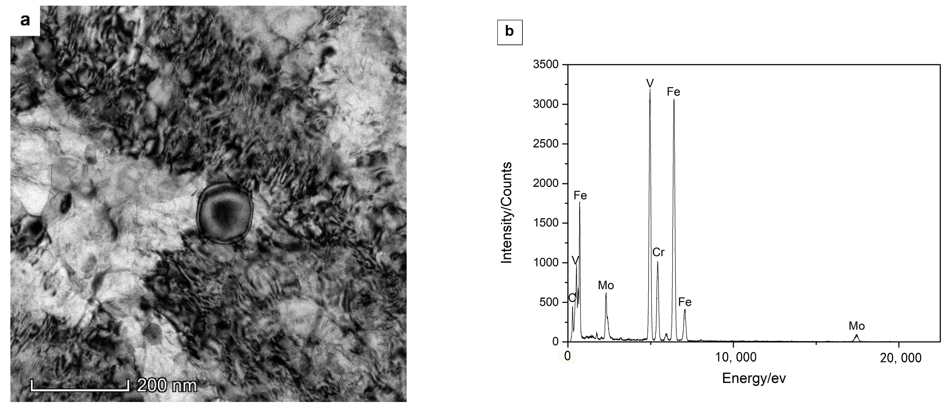
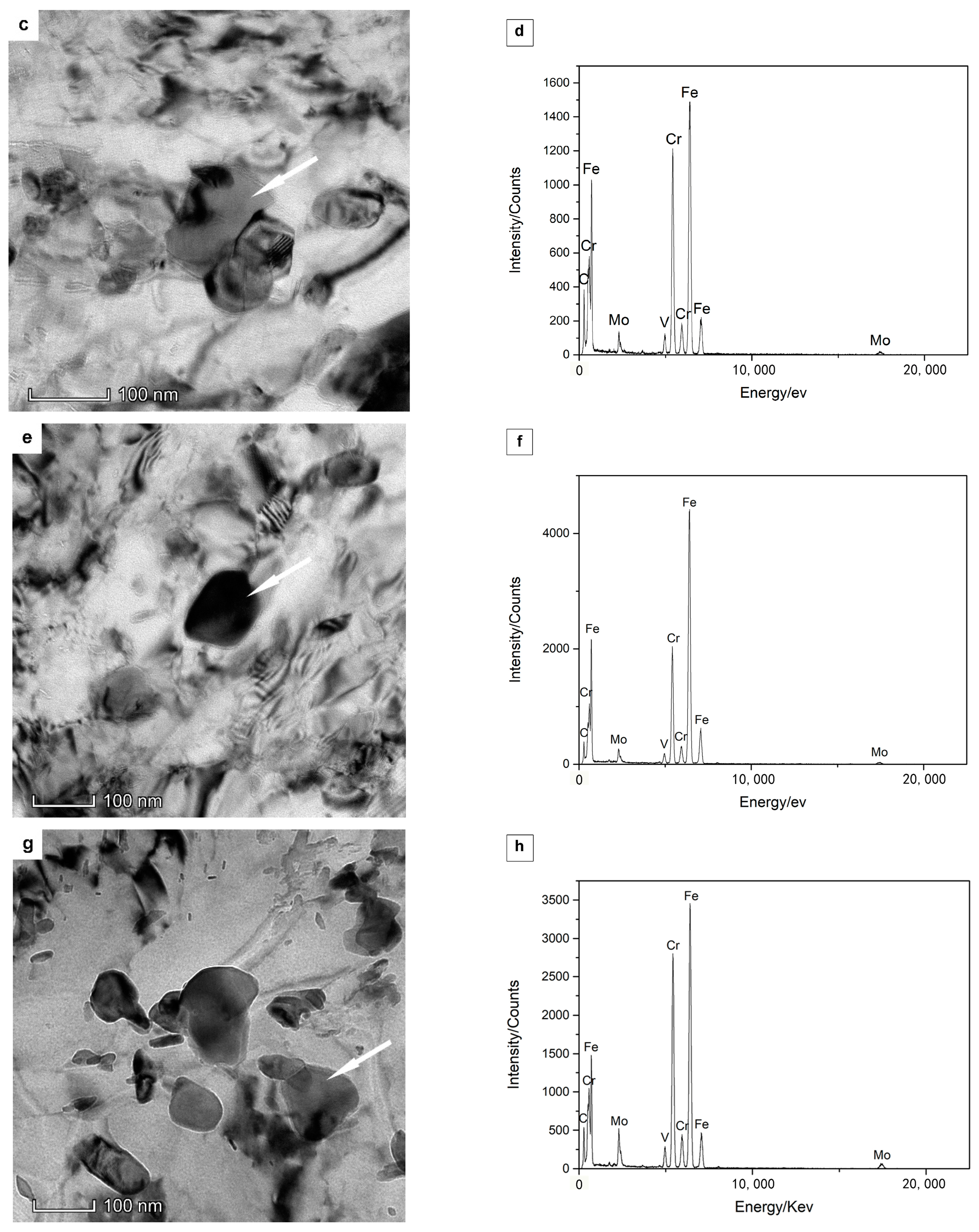
| YCr | YMo | YV | |
|---|---|---|---|
| The spherical carbide in (a) | 0.16 ± 0.01 | 0.25 ± 0.01 | 0.86 ± 0.02 |
| The smaller elliptical carbide in (c) | 0.69 ± 0.02 | 0.16 ± 0.01 | 0.06 ± 0.01 |
| The elliptical carbide in (e) | 0.48 ± 0.01 | 0.06 ± 0.01 | 0.03 ± 0.01 |
| The larger elliptical carbide in (g) | 1.19 ± 0.04 | 0.31 ± 0.01 | 0.10 ± 0.01 |
Publisher’s Note: MDPI stays neutral with regard to jurisdictional claims in published maps and institutional affiliations. |
© 2022 by the authors. Licensee MDPI, Basel, Switzerland. This article is an open access article distributed under the terms and conditions of the Creative Commons Attribution (CC BY) license (https://creativecommons.org/licenses/by/4.0/).
Share and Cite
Xie, Y.; Cheng, X.; Wei, J.; Luo, R. Characterization of Carbide Precipitation during Tempering for Quenched Dievar Steel. Materials 2022, 15, 6448. https://doi.org/10.3390/ma15186448
Xie Y, Cheng X, Wei J, Luo R. Characterization of Carbide Precipitation during Tempering for Quenched Dievar Steel. Materials. 2022; 15(18):6448. https://doi.org/10.3390/ma15186448
Chicago/Turabian StyleXie, Yixin, Xiaonong Cheng, Jiabo Wei, and Rui Luo. 2022. "Characterization of Carbide Precipitation during Tempering for Quenched Dievar Steel" Materials 15, no. 18: 6448. https://doi.org/10.3390/ma15186448
APA StyleXie, Y., Cheng, X., Wei, J., & Luo, R. (2022). Characterization of Carbide Precipitation during Tempering for Quenched Dievar Steel. Materials, 15(18), 6448. https://doi.org/10.3390/ma15186448