Article

Dynamic Response of UHMW-PE Composite Armors under Ballistic Impact of Blunt Projectiles

1
School of Mechanical Engineering, Nanjing University of Science and Technology, Nanjing 210094, China
2
Nanjing Changjiang Electronics Group Co., Ltd., Nanjing 210037, China
*
Author to whom correspondence should be addressed.
Materials 2022, 15(16), 5594; https://doi.org/10.3390/ma15165594
Submission received: 8 July 2022 / Revised: 8 August 2022 / Accepted: 11 August 2022 / Published: 15 August 2022
(This article belongs to the Special Issue Metals Deformation Processes: Fundamental and Applications)

Abstract

:
To study the dynamic response of UHMW-PE composite armor under ballistic impact, two kinds of UHMW-PE composite armors are designed. Both of them are composed of UHMW-PE laminates and steel face sheets of Q235. The blunt projectile is made of 35CrMnSiA, with a cylinder shape. By numerical simulation, the dynamic response and deformation of composite armors are obtained under the penetration of the projectile. With the increase of impact velocity, the penetration depth increases nearly linearly, with a more severe tendency of swaging in the projectile. Then, experiments are carried out to validate the numerical simulation results. Based on a ballistic gun with a caliber of 14.5 mm, the projectiles are fired with a velocity from 680 m/s to 1300 m/s. The penetration into the composite armor can be divided into an initial shear plugging stage and the following bulging and delamination stage. Based on the theoretical analysis, the shear strength in the shear plugging stage can be estimated. Associated with typical experimental results, numerical simulation is suitable to predict the bulging characteristics of the composite armor. The failure mode of the composite armors under the impact of blunt projectiles is determined, and the failure mechanism is analyzed. The penetration results in the experiment agree well with the numerical simulation results, which validate the correctness of the numerical simulation models. The research results can be significant in the design of composite armor with UHMW-PE laminates.

1. Introduction

Polymer-based fiber-reinforced composites such as ultra-high molecular weight polyethylene (UHMW-PE) composites have gained more and more attention, and they are increasingly being employed in the defence industry to protect important structures from ballistic impact [1,2,3].
The ballistic performance of UHMW-PE has been studied both from experiments and numerical simulation. L. H. Nguyen et al. [4,5,6,7,8] proposed the numerical methodology for hydrocode analysis of UHMW-PE composite under ballistic impact and carried out experimental research to validate the results. Deflection and bulging, or a two-stage penetration process composed of shear plugging and the formation of a transition plane and bulging were the predominant failure modes of PE with different thicknesses under ballistic impact. Through fractographic observations on laminates, the determined sequence of failure modes is delamination, ply splitting and fibre kinking [9]. Based on the principle of conservation of energy, the relationship between deformation and energy dissipation of PE [10] and an analytical model to predict the ballistic limit of the PE laminate [2] were studied.
Sandwich structures consisting of thin face sheets and low-density non-metal cores have been widely studied [11,12] and can provide reference and methodology in the application of UHMW-PE. UHMW-PE has been used as part of other composite armors such as 30CrMnMo-UHMWPE Composite Armor [13], metal/UHMWPE/SiC multi-layered composite [14], Ceramic/UHMWPE Armors [15], etc., [16].
Following on from these findings, there is still limited report and understanding of the dynamic response of composite armors of UHMW-PE laminates and steel sheets. In this paper, two kinds of UHMW-PE composite armors are designed; both of them are composed of UHMW-PE laminates and steel face sheets of Q235. By numerical simulation and experimentation, the dynamic response of UHMW-PE composites armor under typical ballistic impact is investigated.

2. Design of the Armor and Projectile

There are two types of UHMW-PE composite armors being developed, both of which are made up of inner UHMW-PE laminates and steel face sheets. For reasonably acceptable strength, low price and wide availability, Q235 steel is selected as the face and back sheets. Typical UHMW-PE laminate with a material grade of FDB4-HW-S1 is also selected. The thickness of the UHMW-PE laminate remains constant at 20 mm; however, the thickness of the two front and back face sheets is 6 mm, as shown in Figure 1. The structure of armor with two layers of UHMW-PE is shown in Figure 1a, and the structure of armor with three layers of UHMW-PE is shown in Figure 1b. Each layer of armor has the same in-plane dimension of 300 mm × 300 mm. The two varieties of UHMW-PE composite armors have total thicknesses of 52 mm and 72 mm, respectively. Due to the existence of a binder layer between the PE and steel sheet, the total thickness of each type of armor may increase by 1 mm. Table 1 show the material properties of Q235 steel.
The structure of a blunt projectile with a diameter of 12.8 mm, a height of 40 mm and a mass of 40 g is shown in Figure 2. The projectile is made of 35CrMnSiA.

3. Numerical Simulation and Analysis

3.1. Setup of Numerical Model

To understand and predict the dynamic response of UHMW-PE composite armor under ballistic impact, three-dimensional numerical models are developedd using AUTODYN non-linear software. The version of AUTODYN is v11.0 in software of ANSYS 11.0, located in Nanjing, China.
As shown in Figure 3, all of the components in the numerical simulation are modeled with the 3D Lagrange algorithm in AUTODYN. Combing computational efficiency and accuracy, the half 3D model is carried out, with a mesh size of 1.2–1.5 mm per grid. With the grid size, the numerical models could yield acceptable accuracy with reasonable simulation time. The mesh is shown in the grid model on the left, and the numerical model is shown on the right. Fixed boundaries are deployed on the edge of the target. Different initial velocities are applied to the flat nose projectile to simulate penetration behavior with different velocities.
The material models of the projectile, face sheet and UHMW-PE laminate are listed in Table 2. In the numerical models, the shock equation of state, also called Grüneisen, is employed in conjunction with the Johnson–Cook constitutive model to simulate the dynamic response of the projectile and the face sheet. The Grüneisen EOS [17] can be used to describe how the materials interact with the shock wave and is based on Hugoniot’s relation between the vs and the vp, as vs = c0 + svp, where vs is the shock wave velocity, vp is the material particle velocity, c0 is the wave speed and s is a material-related coefficient. The expression of the equation of the state of Grüneisen for the compressed state is:
P = ρ 0 C 2 μ [ 1 + ( 1 γ 0 2 ) μ a 2 μ 2 ] [ 1 ( S 1 1 ) μ S 2 μ 2 μ + 1 S 3 μ 3 ( μ + 1 ) 2 ] + ( γ 0 + a μ ) E .
In the expanded state,
P = ρ 0 C 2 μ + ( γ 0 + a μ ) E
where C is the intercept of velocity curve between shock wave and particle, S1, S2, and S3 represent the slope of the vsvp curve, γ0 is the coefficient of Grüneisen and a is the one-order correction of γ0. μ = ρ/ρ0 − 1 is a non-dimensional coefficient based on initial and instantaneous material densities. The parameters of the Grüneisen equation of state are listed in Table 3.
The Johnson–Cook model [18,19] is a widely used constitutive model which incorporates the effect of strain rate-dependent work hardening and thermal softening. The Johnson–Cook constitutive relation is provided by:
σ = ( A + B ε n ) ( 1 + C ln ε ˙ ε ˙ 0 ) ( 1 T m )
where ε is the plastic strain, and the temperature factor is expressed as:
T = T T r T m T r
where Tr is the room temperature, and Tm is the melt temperature of the material. A, B, n, C and m are material-related parameters. The material parameters of 35CrMnSiA Q235 steel are presented in Table 4.
The orthotropic material model proposed by Long H. Nguyen et al. [5] was used for modeling the dynamic behavior of the UHMWPE layer subjected to ballistic impact. The correctness and accuracy were validated by Pengcheng Hu et al. [15]. The material model consists of a non-linear equation of state of orthotropic, a strength model and a failure model. The constitutive response of the material in the elastic regime is described as the orthotropic EOS composed of volumetric and deviatoric components. The pressure is defined by:
P = P ( ε v o l , e ) 1 3 ( C 11 + C 21 + C 31 ) ε 11 d 1 3 ( C 12 + C 22 + C 32 ) ε 22 d 1 3 ( C 13 + C 23 + C 33 ) ε 33 d
where Cij are the coefficients of the stiffness matrix. ε i j d refer to the deviatoric strains in the principal directions. The volumetric component P ( ε v o l , e ) is defined by the Mie-Grüneisen EOS:
P ( ε v o l , e ) = P r ( v ) + Γ ( v ) v [ e e r ( v ) ]
where, v, e and Γ(v) represent the volume, internal energy and the Grüneisen coefficient, respectively. Pr(v) is the reference pressure, and er(v) is the reference internal energy. The quadratic yield surface was adopted as the material strength model to describe the non-linear, irreversible hardening behavior of the composite laminate:
f ( σ i j ) = a 11 σ 11 2 + a 22 σ 22 2 + a 33 σ 33 2 + 2 a 12 σ 11 σ 22 + 2 a 23 σ 22 σ 33 + 2 a 13 σ 11 σ 33 + 2 a 44 σ 23 2 + 2 a 55 σ 31 2 + 2 a 66 σ 12 2 = k
where aij are the plasticity coefficients, and σij represents the stresses in the principal directions of the material. Furthermore, the state variable, k, is used to define the border of the yield surface. It is described with a master effective stress-effective plastic strain curve defined by 10 piecewise points to consider the effect of strain hardening.
In the numerical models, the failure model of the orthotropic material is based on a combined stress criterion presented as follows:
( σ i i S i i ( 1 D i i ) ) 2 + ( σ i j S i j ( 1 D i j ) ) 2 + ( σ k i S k i ( 1 D k i ) ) 2 1   for   i , j , k = 1 , 2 , 3
where Sii is the failure strength in the respective directions of the material, and Dii is the damage parameter following a linear relationship with stress and strain as below:
D i i = L σ i i , f ε c r 2 G i i , f
where L is the characteristic cell length, εcr refers to the crack strain, and Gii,f presents the fracture energy in the direction of damage.
The corresponding parameters of the material model for the orthotropic equation of state are provided in Table 5, and material constants for orthotropic yield strength are listed in Table 6.

3.2. Numerical Results and Analysis

Table 7 present the numerical simulation results of the blunt projectile penetrating the composite armor with two layers of PE. v is the impact velocity of the blunt projectile, and 
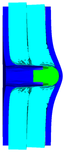
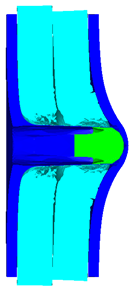
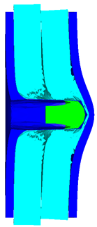
p is the depth of penetration. With the increase of impact velocity, the penetration depth increases gradually, and the projectile will have a more severe tendency to swage after penetration. After impact, due to the reflection of stress waves in the penetration process, the steel sheet and PE laminates may separate away from each other. The penetration depth p is measured from the head of the projectile to the baseline of the front sheet at the end of the simulation.
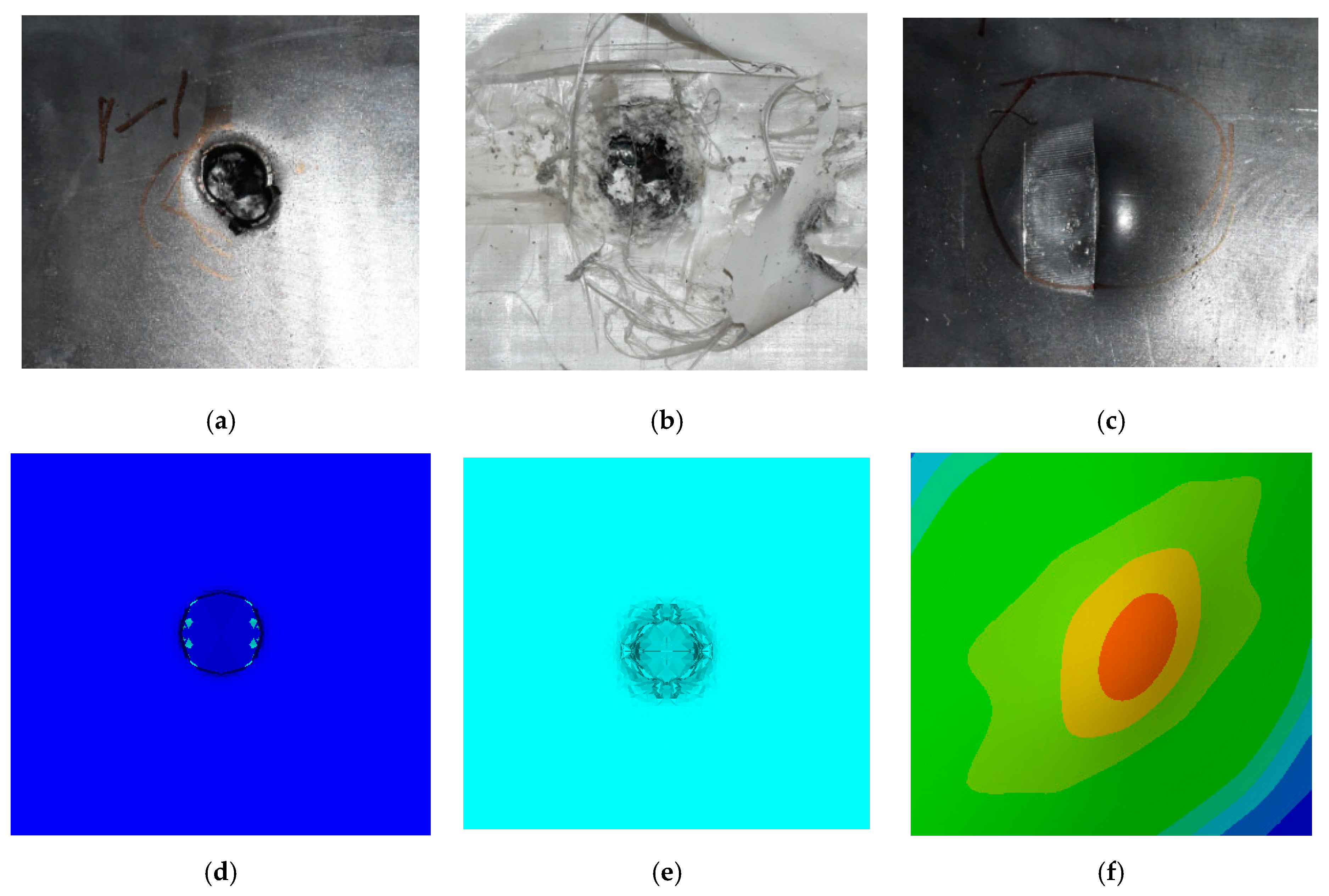
As shown in 
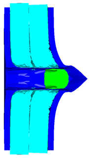
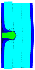
Table 7, when the impact velocity reaches 1300 m/s, the projectile will pass through the armor. As shown in Figure 4, the Von-Mises stress contour of the back sheet can be solid evidence to predict the failure of the steel sheet and perforation of the armor.
Table 8 present the numerical simulation results of the blunt projectile penetrating the composite armor with three layers of PE. With the increase of impact velocity, the penetration depth increases gradually. The projectile will have a more severe tendency of swaging. When the impact velocity exceeds 1000 m/s, the back sheet deforms severely and separates away from the PE laminates, mainly due to the reflection of stress wave in the penetration process within the interaction with different layers.
As shown in 
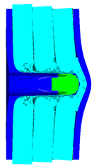
Table 8, when the impact velocity reaches 1400 m/s, the projectile will pass through the armor. As presented in Figure 5, the Von-Mises stress contour of the back sheet can be solid evidence to predict the failure of the steel sheet and perforation of the armor with three layers of PE laminates.
It can be concluded from the numerical simulation: (1) the established numerical simulation models for the composite armors are able to predict the penetration and deformation of the target. (2) With the increase of impact velocity, the penetration depth increases gradually both for the armors with two and three layers of PE. (3) By numerical simulation, at the velocity of 1300 m/s, the blunt projectile could penetrate through the composite armor with two layers of PE. While at the velocity of 1400 m/s, the blunt projectile could penetrate through the composite armor with three layers of PE.

4. Experimental Details and Results

4.1. Design of the Experiment

The state of the projectile in the test is presented in Figure 6. The sabot is designed to meet the launch requirements with nylon material. The state of the sabot and blunt projectile is presented in Figure 6a. As shown in Figure 6b,c, the projectile was firstly assembled in the sabot and then assembled in the shell case together with the sabot. The blunt projectile was fired from a 14.5 mm caliber ballistic gun. When the structure and mass of the projectile stay constant, the muzzle velocity of the projectile usually has a linear relationship with the mass of the propellant within a certain range. Thus, by adjusting the mass of propellant in the shell case, the required velocities of the projectile can be obtained.
Figure 7 show the states of the armors used in the test. The armors were clamped to the rear base on the steel shelf. Two tinfoil targets were placed in front of the armor to measure the initial velocity of the projectile. The layout of the ballistic impact experiment is presented in Figure 8.

4.2. Experimental Results

Table 9 show the ballistic impact results of armors with two layers of PE, with typical ballistic velocity ranges from 700 m/s to 1200 m/s. Specifically, with the velocity from 759 m/s to 1174 m/s, the blunt projectile could not perforate the armor with two layers of PE. Only deformation and bulging with different degrees occurred.
The perforation dimensions are listed in Table 10. Within the velocity range from 760 m/s to 1174 m/s, the aperture diameter stayed around 20 mm. At the velocity of 1174 m/s, the depth of penetration ranged from 64 to 66 mm. The value of 66.12 mm was adopted as the penetration result of impact velocity of 1174 m/s, which can be drawn in a 2D drawing. It was concluded that with the increase of penetration depth, the bulging deformation grows. The deformation and perforation profiles of armor with two layers of PE are presented in Figure 9.
It can be concluded from Table 9 and Figure 9 that penetration into the composite armor can be divided into a two-stage process [4]: (1) an initial shear plugging stage, where there is little deflection of the target. (2) This is followed by the bulging or breakout of a sub-laminate. With large deformation and bulging, the delamination may extend to the edge of the PE laminate, which results in some sub-laminates separating and breaking the PE laminate into multiple pieces. With the increase of bulging and deformation, the depth of penetration may exceed the initial total thickness of the composite armor of 53 mm.
With the increase of impact velocity, the penetration depth increases gradually and nearly linearly, which is presented in Figure 10. The numerical simulation results agree well with the experimental results.
Table 11 show the ballistics impact results of armors with three layers of PE, with the impact velocity ranging from 683 m/s to 1304 m/s. The velocity range is similar to the values in Table 9. As the projectile in tests No.2 and No.4 turned over with large angles of attack, the penetration results are not considered. With the velocity range from 683 m/s to 1304 m/s, the blunt projectile could not perforate the armor with three layers of PE. Only deformation and bulging with different degrees occurred. The perforation dimensions are listed in Table 12; the aperture diameter remained around 21 mm.
Figure 11 show the deformation and perforation profiles of armor with three layers of PE. Associated with Table 9 and Figure 11, it can be concluded that the two-stage process in penetration still applies here. The transition between the two penetration stages is a complex physical phenomenon, and it has been proposed that transition is mainly due to delamination induced by shear-dominated stresses in bending [9]. According to the projectiles’ penetration states in the test, the penetration results are considered in the analysis, except for tests No.2 and No.4. The pv curve of the blunt projectile penetration into the armor with three layers of PE is presented in Figure 12. With the increase of impact velocity, the penetration depth increases almost linearly, and the numerical simulation results agree quite well with the experimental results from the velocity of 683 m/s to 1304 m/s.

4.3. Discussion and Analysis

Penetration into the composite armor can be divided into a two-stage process: (a) an initial shear plugging stage; (b) the following bulging and delamination stage. Before penetrating through the composite armor, the kinetic energy of the projectile is assumed to be equal to the energy absorbed during the two-stage process, so
E total = E S + E B = 1 2 m p v i 2
where E total is the total kinetic energy of the projectile, mp is the mass of the blunt projectile, vi is the impact velocity of the projectile, ES is the energy absorbed in shear plugging and EB is the energy absorbed in the bulging stage.
Figure 13 show the schematic diagram of the two-stage penetration composed of shearing and bulging stages. In the first penetration stage, the energy absorbed in shear plugging is equal to the work required to produce a shear plug composed of Q235 steel and partial PE laminate around the circumference of the blunt projectile, where the shear area is the product of the perimeter and the thickness of the material in the shear plugging process, which can be expressed by
E S = 0 t s τ max ( 2 π r p ) tdt = τ Q 235 π r p t 0 2 + τ max π r p t S 2
where τ Q 235 is the shear strength of steel Q235, τ max is the effective through-thickness shear strength of the laminate, rp is the radius of the hole and β is a non-dimensional multiplier larger than the projectile radius, t0 is the thickness of the front sheet and tS is the PE thickness penetrated through shear plugging. By assuming penetration by transverse shearing only, the thickness of the plug is equal to the measured depth of penetration [4], then
1 2 m p v i 2 = τ max π r p p 2 + τ Q 235 π r p ( p t 0 ) 2 .
Equation (12) can be used to obtain the effective through-thickness shear strength using the test results, and the calculated data of shear strength τ max is presented in Table 13. For the composite armor with two layers of PE, when the impact velocity v exceeds 1139 m/s, the shear strength τ max will stabilize at about 13 GPa. In contrast, for the composite armor with three layers of PE, when the impact velocity v exceeds 1175 m/s, the shear strength τ max will reach a stable value of around 15 GPa. The calculated effective shear strengths are much higher than the laminate under ballistic impact without a steel sheet in the front and back, which are calculated to be from 388 MPa to 657 MPa [4]. This may be due to the constraining effect of the Q235 steel sheet, which enhances the armors’ resilience under ballistic impact.
In the second penetration stage, based on the conservation of momentum, the momentum of the projectile before bulging equals the total momentum of the projectile and the deformed zone of the armor. As shown in Figure 13, the momentum can be expressed as
m p v B = ( m p + m B + m 0 ) v
v B = v ( 1 + m B m p + m 0 m p ) = v ( 1 + β 2 π r p t B ρ PE m p + β 2 π r p t 0 ρ Q 235 m p )
where vB is the projectile velocity before bulging, v is the velocity of the combined projectile and bulging mass of PE and steel sheet and mB and m0 are the mass of the target involved in the bulging stage of PE and back sheet. The energy absorbed in the bulging stage can be provided by
E B = 1 2 m p v B 2 .
Due to the energy transferred in the bulging stage, the PE laminate and the back sheet deform severely and are able to resist the penetration of the blunt projectile at a rather high velocity. As the complexity phenomenon in bulging, numerical simulation associated with typical experimental results is suitable to predict the bulging characteristics of the composite armor. As shown in Figure 14, the perforation and deformation properties of (d), (e) and (f) in the numerical simulation match well with the experimental results of (a), (b) and (c).
By comparing the penetration results of two types of armors, it can be concluded that: (1) the sabot is designed to meet the launch requirements, which could be used in the ballistic gun to launch the blunt projectile with a velocity range of 680 m/s to 1300 m/s. (2) The two kinds of designed armors could be used to resist the impact of a blunt projectile, even at a velocity of 1170 m/s. By comparison, the armor with two layers of PE can be enough to resist the impact of a blunt project under the velocity of 1174 m/s. In contrast, the armor with three layers of PE can be enough to resist the impact of a blunt project under the velocity of 1304 m/s. (3) With the increase of impact velocity, the penetration depth increases gradually both for the armor of two layers and three layers of PE. (4) The penetration into the composite armor can be divided into an initial shear plugging stage and the following bulging and delamination stage. (5) Based on the experimental results, it may improve delamination-induced shear stress conditions to render a safer transition without deep penetration by increasing the shear strength and bond strength of the PE laminates. The failure mechanism of the composite armor is analyzed by theoretical models; based on the theoretical analysis, the through-thickness shear strength can be estimated, and numerical simulation associated with typical experimental results is suitable to predict the bulging characteristics of the composite armor.

5. Conclusions

Two types of multi-layered composite armors made up of inner UHMW-PE laminates and steel face sheets were proposed for the protection of important structures in the defence industry. A study of the dynamic response of UHMW-PE composite armor under typical ballistic impact was carried out. The conclusion can be obtained below:
(1)
Based on a 14.5 mm caliber ballistic gun, two types of UHMW-PE composite armors were designed; both of them are composed of UHMW-PE laminates and steel face sheets of Q235. The nylon sabot was designed to meet the launch requirements, which could be used to launch the blunt projectile with a velocity range of 680 m/s to 1300 m/s.
(2)
The established numerical simulation models for the composite armors were able to predict the penetration and deformation of the target. Using the orthotropic equation of state and Orthotropic yield strength model, a numerical model can be set up to simulate the dynamic response of UHMW-PE laminate under the ballistic impact of a blunt projectile. According to numerical simulation results, the blunt projectile was able penetrate through the composite armor with two layers of PE at a velocity of 1300 m/s, and it could penetrate through the composite armor with three layers of PE at a velocity of 1400 m/s.
(3)
The two kinds of designed armors could be used to resist the impact of a blunt projectile even at a velocity of 1170 m/s. By comparison, the armor with two layers of PE can be enough to resist the impact of a blunt project under the velocity of 1174 m/s. At the same time, the armor with three layers of PE can be enough to resist the impact of a blunt project under the velocity of 1304 m/s.
(4)
The failure mode of the composite armor can be determined, and the penetration into the composite armor can be divided into an initial shear plugging stage and the following bulging and delamination stage. With the increase of impact velocity, the penetration depth increases gradually both for the armor of two layers and three layers of PE. The projectile will have a more severe tendency of swaging.
(5)
The failure mechanism of the composite armor was analyzed by theoretical models of a two-stage process. Based on the theoretical analysis, the through-thickness shear strength was estimated, and numerical simulation associated with typical experimental results were suitable to predict the bulging characteristics of the composite armor.
The numerical and experimental results provide necessary data support for the analysis of composite structure dynamic response under fragment impact and verify the correctness of the numerical simulation method. The research results are significant in the design of composite armor with UHMW-PE laminates. By combining steel face sheets and UHMW-PE laminates, it is possible to obtain composite armor that is good enough to resist the penetration of blunt projectiles.

Author Contributions

Methodology, validation, formal analysis, writing—original draft preparation, funding acquisition, L.D.; supervision, visualization;writing—review, validation, X.G.; writing—review and editing, supervision, project administration, P.S.; supervision, data curation, resources, X.K.; data curation, writing-editing, Y.Z. All authors have read and agreed to the published version of the manuscript.

Funding

This research was funded by National Natural Science Foundation of China (Grant No. 11802142) and project of the State Key Laboratory of Explosion Science and Technology (Grant No. KFJJ20-08M).

Data Availability Statement

The raw and processed data generated during this study will be made available upon reasonable request.

Acknowledgments

The authors thank the National Natural Science Foundation of China (Grant No. 11802142) and the project of the State Key Laboratory of Explosion Science and Technology (Grant No. KFJJ20-08M).

Conflicts of Interest

The authors declare no conflict of interest.

Nomenclature

symbols
ρdensity
ρ0initial density
Ppressure
vsshock wave velocity
vpmaterial particle velocity
c0wave speed
sa material-related coefficient
Cintercept of vsvp curve
μa non-dimensional coefficient
γ0coefficient of Grüneisen
S1, S2, S3slope of the vsvp curve
aone-order correction of γ0
σeffective yield stress
εeffective plastic strain
ε ˙ strain rate rate
ε ˙ 0 quasi-static threshold strain rate
Ainitial yield stress
Bhardening constant
nwork-hardening coefficient
Cstrain rate constant
mthermal softening exponent
Ttemperature
Tmmelting point
Trreference temperature
T*homologous temperature
Cijcoefficients of the stiffness matrix
ε i j d deviatoric strains
P ( ε v o l , e ) volumetric strain
vvolume
einternal energy
Γ(v)Grüneisen coefficient
Pr(v)reference pressure
er(v)reference internal energy
aijplasticity coefficients
σijstresses in the principal directions of the material
kdefine the border of the yield surface
Siifailure strength in the respective directions of the material
Diidamage parameter
Lcharacteristic cell length
εcrcrack strain
Gii,ffracture energy in the direction of damage
pdepth of penetration
vinitial velocity
E total total kinetic energy of the projectile
mpmass of the blunt projectile
viimpact velocity of the projectile
ESenergy absorbed in shear plugging
EBenergy absorbed in the bulging stage
τ Q 235 shear strength of steel Q235
τ max effective through-thickness shear strength of the laminate
rpradius of the hole
βa non-dimensional multiplier
t0thickness of the front sheet
tSPE thickness penetrated through shear plugging
mpmass of the projectile
vBprojectile velocity before bulging
mBmass of the target involved in the bulging stage of PE
m0mass of the target involved in the bulging stage back sheet

References

  1. Phoenix, S.L.; Porwal, P.K. A new membrane model for the ballistic impact response and V50 performance of multi-ply fibrous systems. Int. J. Solids Struct. 2003, 40, 6723–6765. [Google Scholar] [CrossRef]
  2. Chen, C.; Zhu, X.; Wang, J. Mechanism of high-velocity blunt-nosed projectiles penetrating moderately thick UHMWPE fiber reinforced plastic laminate. Acta Mater. Compos. Sin. 2013, 30, 226–235. [Google Scholar]
  3. Mei, Z.; Zhu, X.; Zhang, L. Ballistic protective mechanism of FRC laminates. Acta Mater. Compos. Sin. 2006, 23, 143–149. [Google Scholar]
  4. Long, H.N.; Ryan, S.; Cimpoeru, S.J.; Mouritz, A.P.; Orifici, A.C. The effect of target thickness on the ballistic performance of ultra high molecular weight polyethylene composite. Int. J. Impact Eng. 2015, 75, 174–183. [Google Scholar]
  5. Nguyen, L.H.; Lässig, T.; Ryan, S.; Riedel, W.; Mouritz, A.P.; Orifici, A.C. A methodology for hydrocode analysis of ultra-high molecular weight polyethylene composite under ballistic impact. Compos. Part A 2016, 84, 224–235. [Google Scholar] [CrossRef]
  6. Lässig, T.; Nguyen, L.; May, M.; Riedel, W.; Heisserer, U.; van der Werff, H.; Hiermaier, S. A non-linear orthotropic hydrocode model for ultra-high molecular weight polyethylene in impact simulations. Int. J. Impact Eng. 2015, 75, 110–122. [Google Scholar] [CrossRef]
  7. Nguyen, L.H.; Lässig, T.R.; Ryan, S.; Riedel, W.; Mouritz, A.P.; Orifici, A.C. Numerical Modelling of Ultra-High Molecular Weight Polyethylene Composite under Impact Loading. Procedia Eng. 2015, 103, 436–443. [Google Scholar] [CrossRef]
  8. Nguyen, L.H.; Ryan, S.; Cimpoeru, S.J.; Mouritz, A.P.; Orifici, A.C. The Efficiency of Ultra-High Molecular Weight Polyethylene Composite Against Fragment Impact. Exp. Mech. 2016, 56, 595–605. [Google Scholar] [CrossRef]
  9. Greenhalgh, E.S.; Bloodworth, V.M.; Iannucci, L.; Pope, D. Fractographic observations on Dyneema composites under ballistic impact. Compos. Part A 2013, 44, 51–62. [Google Scholar] [CrossRef]
  10. Cao, J.; Zhang, J.; Shu, Z.; Ren, L.; Liu, L. Study on the relationship between deformation and energy dissipation of PE plate under impact. Protect. Eng. 2019, 41, 6. [Google Scholar]
  11. Silmane, S.A.; Silmane, A.; Guelailia, A.; Booudjemai, A.; Kebdani, S.; Smahat, A.; Mouloud, D. Hypervelocity impact on honeycomb structure reinforced with bi-layer ceramic/aluminum facesheets used for spacecraft shielding. Mech. Adv. Mater. Struct. 2021, 1–19. [Google Scholar] [CrossRef]
  12. Si, P.; Liu, Y.; Yan, J.; Bai, F.; Huang, F. Ballistic Performance of Polyurea-Reinforced Ceramic/Metal Armor Subjected to Projectile Impact. Materials 2022, 15, 3918. [Google Scholar] [CrossRef] [PubMed]
  13. Zhou, Y.; Li, G.; Fan, Q.; Wang, Y.; Zheng, H.; Tan, L.; Xu, Z. Study on protection mechanism of 30CrMnMo-UHMWPE composite armor. Materials 2017, 10, 405. [Google Scholar] [CrossRef] [PubMed]
  14. Hu, P.; Cheng, Y.; Zhang, P.; Liu, J.; Yang, H.; Chen, J. A metal/UHMWPE/SiC multi-layered composite armor against ballistic impact of flat-nosed projectile. Ceram. Int. 2021, 47, 22497–22513. [Google Scholar] [CrossRef]
  15. Chen, Z.; Xu, Y.; Li, M.; Li, B.; Song, W.; Xiao, L.; Cheng, Y.; Jia, S. Investigation on Residual Strength and Failure Mechanism of the Ceramic/UHMWPE Armors after Ballistic Tests. Materials 2022, 15, 901. [Google Scholar] [CrossRef] [PubMed]
  16. Cheng, Y.; Xie, J.; Li, Z.; Liu, J.; Zhang, P. Damage Response Characteristics of UHMWPE/aluminum Foam Composite Sandwich Panel Subjected to CombinedBlast and Fragment Loadings. Acta Armamentarii 2021, 42, 1753. [Google Scholar]
  17. Andre, M.M. Dynamic Behavior of Materials; John Wiley & Sons: Hoboken, NJ, USA, 1994. [Google Scholar]
  18. Johnson, G.R.; Cook, W.H. A constitutive model and data for metals subjected to large strains, high strain-rates and high temperatures. In Proceedings of the Seventh International Symposium on Ballistics, The Hague, The Netherlands, 19–21 April 1983; p. 541. [Google Scholar]
  19. Johnson, G.R.; Cook, W.H. Fracture characteristics of three metals subjected to various strains, strain rates, temperatures, and pressres. Eng. Fract. Mech. 1985, 21, 31–48. [Google Scholar] [CrossRef]
Figure 1. Structures of UHMW-PE composite armors. (a) Armor with two layers of PE. (b) Armor with three layers of PE.
Materials 15 05594 g001
Figure 2. Structure of the blunt projectile.
Materials 15 05594 g002
Figure 3. Grid and numerical models of armor impacted by blunt projectile. (a) Armor with two layers of UHMW-PE. (b) Armor with three layers of UHMW-PE.
Materials 15 05594 g003
Figure 4. Von-Mises stress contour of armor at the impact velocity of 1300 m/s.
Materials 15 05594 g004
Figure 5. Von-Mises stress Contour of armor at the impact velocity of 1400 m/s.
Materials 15 05594 g005
Figure 6. Photograph of the projectile in the test. (a) The projectile and sabot. (b) Assembly of the projectile in the sabot. (c) Assembly of the projectile in the shell case.
Materials 15 05594 g006
Figure 7. Photograph of the armors in the test. (a) Front view. (b) Side view.
Materials 15 05594 g007
Figure 8. Layout of the ballistic impact experiment.
Materials 15 05594 g008
Figure 9. Deformation and perforation profiles of armor with two layers of PE (unit: mm). (a) v = 759 m/s. (b) v = 1139 m/s. (c) v = 1174 m/s.
Materials 15 05594 g009
Figure 10. p–v curve of the blunt projectile penetration into the armor with two layers of PE.
Materials 15 05594 g010
Figure 11. Deformation and perforation profiles of armor with three layers of PE (unit: mm). (a) v = 683 m/s. (b) v = 778 m/s. (c) v = 1175 m/s. (d) v = 1190 m/s. (e) v = 1127 m/s. (f) v = 1304 m/s.
Materials 15 05594 g011
Figure 12. p–v curve of the blunt projectile penetration into the armor with three layers of PE.
Materials 15 05594 g012
Figure 13. Schematic diagram of the two-stage penetration composed of shearing and bulging stages.
Materials 15 05594 g013
Figure 14. Comparison between the results of the experiment and the numerical simulation at the impact velocity of 759 m/s for composite armor with two layers of PE. (a) Face sheet. (b) Sub-laminate. (c) Deformation on the back sheet. (d) Face sheet. (e) Sub-laminate. (f) Deformation on the back sheet.
Materials 15 05594 g014
Table 1. Material properties of Q235 steel.
SteelYield Strength (MPa)Tensile Strength (MPa)Elongation after Break (%)Poisson’s Ratio (%)Impact Energy Aku (J)
Q235305426300.33≥27
Table 2. Material models used in numerical simulation.
ComponentsMaterialρ (g/cm3)Equation of StateConstitutive Model
Projectile35CrMnSiA7.83ShockJohnson–Cook
Face sheetQ2357.896ShockJohnson–Cook
PE laminatesUHMW-PE0.98OrthoOrthotropic Yield
Table 3. Parameters of Grüneisen equation of state 35CrMnSiA and Q235.
MaterialGrüneisen CoefficientC (m/s)S1S2a
35CrMnSiA2.0234901.48900.47
Q2352.1745691.49000.46
Table 4. Material constants for 35CrMnSiA and Q235.
Steelρ (g/cm3)A (MPa)B (MPa)nCm ε ˙ 0   ( s 1 ) Tr (K)Tm (K)
35CrMnSiA7.837925100.260.0141.0312931793
Q2357.8963502750.360.0221.0012931793
Table 5. Material constants for orthotropic equation of state.
ParametersValueUnitsParametersValueUnits
Reference density0.98g/cm3Shear modulus 122.0 × 10⁶kPa
Young’s modulus 113.62 × 10⁶kPaShear modulus 231.92 × 10⁵kPa
Young’s modulus 225.11 × 10⁷kPaShear modulus 312.0 × 10⁶kPa
Young’s modulus 335.11 × 10⁷kPaVolumetric response: shock Gruneisen coefficient1.64-
Poisson’s ratio 120.013-Parameter C13.57 × 103m/s
Poisson’s ratio 310.5-Parameter S11.3-
Reference temperature293KSpecific heat1.85 × 103J/kgK
Table 6. Material constants for Orthotropic yield strength.
ParametersValueUnitsParametersValueUnits
Plasticity constant 110.016-Eff. plastic strain #10-
Plasticity constant 226 × 10−4-Eff. plastic strain #20.01-
Plasticity constant 336 × 10−4-Eff. plastic strain #30.1-
Plasticity constant 120-Eff. plastic strain #40.15-
Plasticity constant 130-Eff. plastic strain #50.175-
Plasticity constant 230-Eff. plastic strain #60.19-
Plasticity constant 441-Eff. plastic strain #70.2-
Plasticity constant 551.7-Eff. plastic strain #80.205-
Plasticity constant 661.7-Eff. plastic strain #90.21-
// Eff. plastic strain #100.215-
Eff. stress #11.48 × 10³kPaEff. stress #66.0 × 10⁴kPa
Eff. stress #27.0 × 10³kPaEff. stress #78.0 × 10⁴kPa
Eff. stress #32.7 × 10⁴kPaEff. stress #89.8 × 10⁴kPa
Eff. stress #44.0 × 10⁴kPaEff. stress #92.0 × 10⁵kPa
Eff. stress #55.0 × 10⁴kPaEff. stress #101.0 × 10⁶kPa
Table 7. Numerical simulation results of projectile penetrating armor with two layers of PE.
v (m/s)State of Perforation and Deformationp
(mm)
v (m/s)State of Perforation and Deformationp
(mm)
700 Materials 15 05594 i00138.141100 Materials 15 05594 i00261.71
800 Materials 15 05594 i00345.821200 Materials 15 05594 i00465.52
1000 Materials 15 05594 i00557.321300 Materials 15 05594 i006pass through
Table 8. Numerical simulation results of projectile penetrating armor with three layers of PE.
v (m/s)State of Perforation and Deformationp (mm)v (m/s)State of Perforation and Deformationp (mm)
680 Materials 15 05594 i00714.381190 Materials 15 05594 i00857.30
780 Materials 15 05594 i00924.941300 Materials 15 05594 i01066.62
1000 Materials 15 05594 i01143.121400 Materials 15 05594 i012pass through
Table 9. Ballistic impact results of armor with two layers of PE.
Test No.v (m/s)Perforation State in the Front and Back
1759 Materials 15 05594 i013 Materials 15 05594 i014
21139 Materials 15 05594 i015 Materials 15 05594 i016
31174 Materials 15 05594 i017 Materials 15 05594 i018
41174 Materials 15 05594 i019 Materials 15 05594 i020
5752 Materials 15 05594 i021 Materials 15 05594 i022
Table 10. Perforation dimension of armor with two layers of PE.
Test No.12345
Impact velocity v (m/s)759113911741174752
Dimension (mm)Φ21.02 × 45.02Φ19.82 × 62.04Φ19.96 × 64.07Φ20.20 × 66.12Φ19.20 × 44.28
Table 11. Ballistic impact results of armor with three layers of PE.
Test No.v (m/s)Perforation State in the Front and Back
1683 Materials 15 05594 i023 Materials 15 05594 i024
2486 Materials 15 05594 i025 Materials 15 05594 i026
3778 Materials 15 05594 i027 Materials 15 05594 i028
4889 Materials 15 05594 i029 Materials 15 05594 i030
51175 Materials 15 05594 i031 Materials 15 05594 i032
61190 Materials 15 05594 i033 Materials 15 05594 i034
71227 Materials 15 05594 i035 Materials 15 05594 i036
81304 Materials 15 05594 i037 Materials 15 05594 i038
The nameplates on the armour shows parts of the information of the dimension and provider of the composite armours in Chinese.
Table 12. Perforation dimension of armor with three layers of PE.
Test No.1234
Impact velocity v (m/s)683486778889
Dimension (mm)Φ24 × 12.39/Φ20 × 27.20/
Test No.5678
Impact velocity v (m/s)1175119012271304
Dimension (mm)Φ21 × 54.70Φ21 × 57.01Φ21 × 59.50Φ21 × 65.20
Table 13. Depth of penetration for estimating through-thickness shear strength.
Armor TypeImpact Velocity vi (m/s)Depth of Penetration p (mm) τ max   ( GPa )
2 PE75245.027.30
75945.287.41
113962.0412.81
117464.0713.12
117466.1212.71
3 PE68312.3920.42
77827.2012.40
117554.7014.76
119057.0114.54
122759.5014.85
130465.2015.36
Publisher’s Note: MDPI stays neutral with regard to jurisdictional claims in published maps and institutional affiliations.

