
Effect of Annealing Temperature on Microstructure and Properties of Al/Mg Magnetic Pulse Welding Joints

Abstract
:1. Introduction
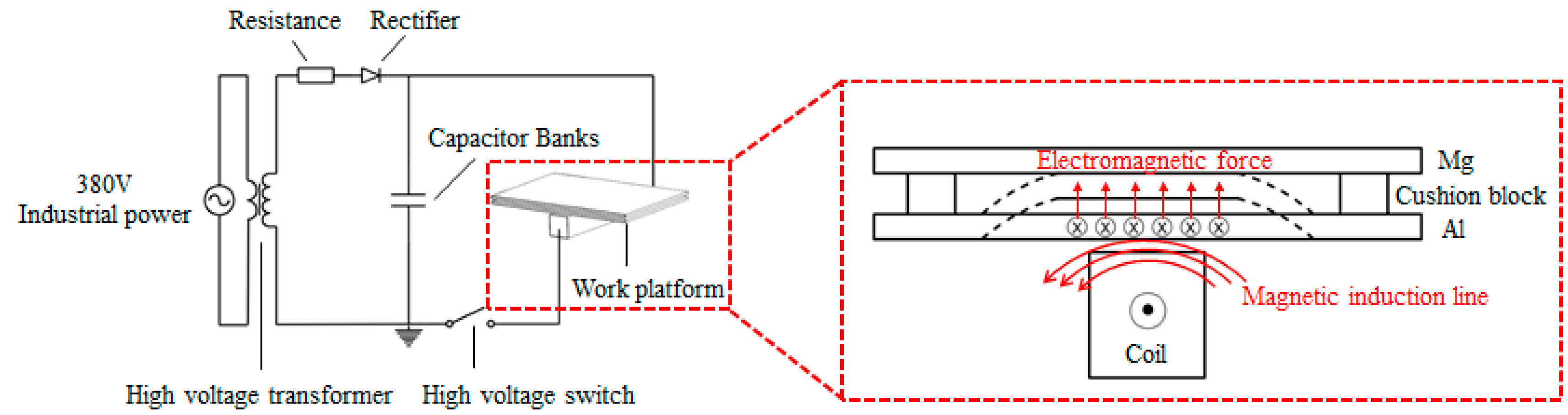
2. Experimental Methods
3. Analysis of Macroscopic Morphology and Microstructure of Welded Joints
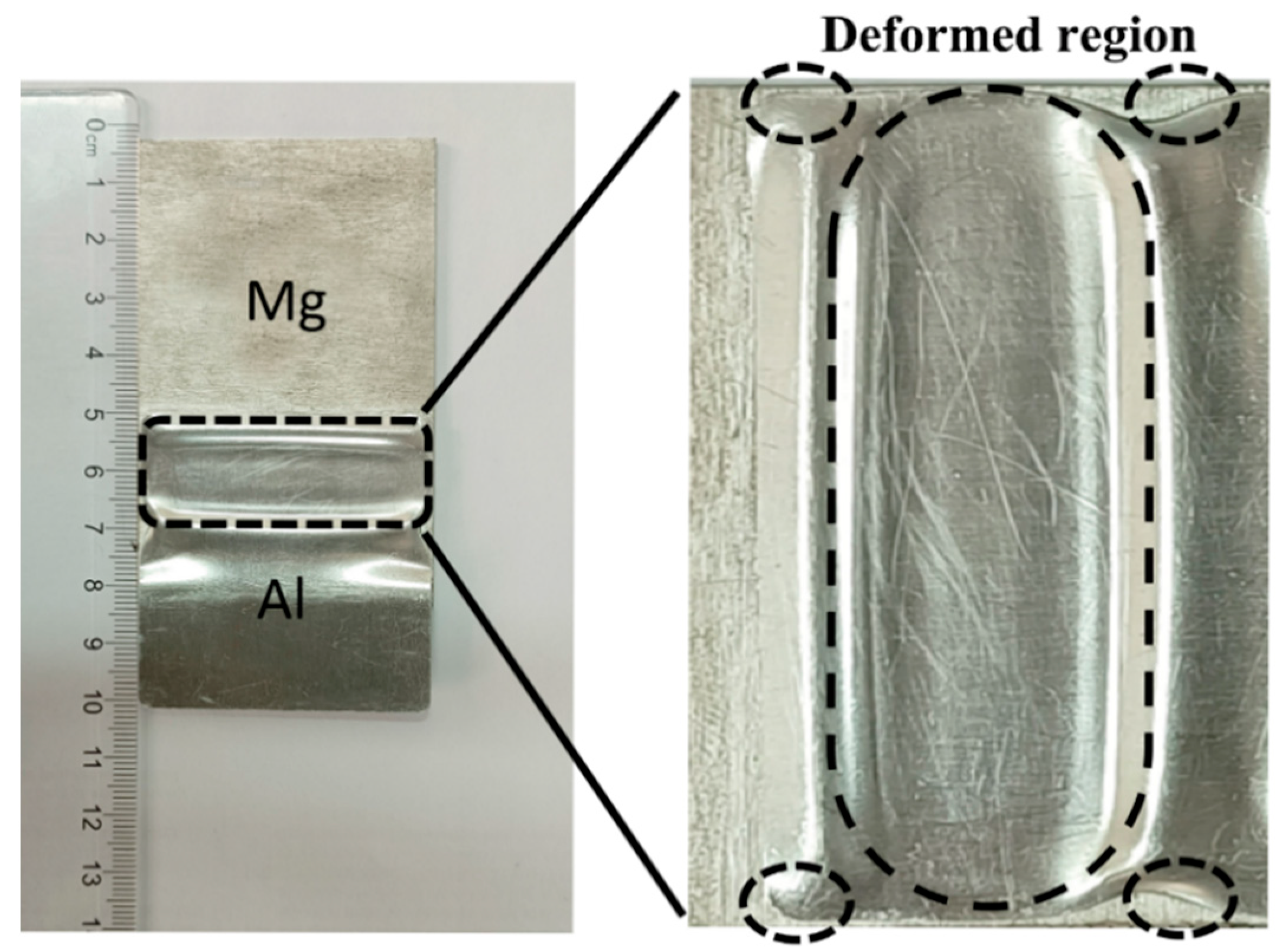
3.1. Macroscopic Morphology of Welded Joints
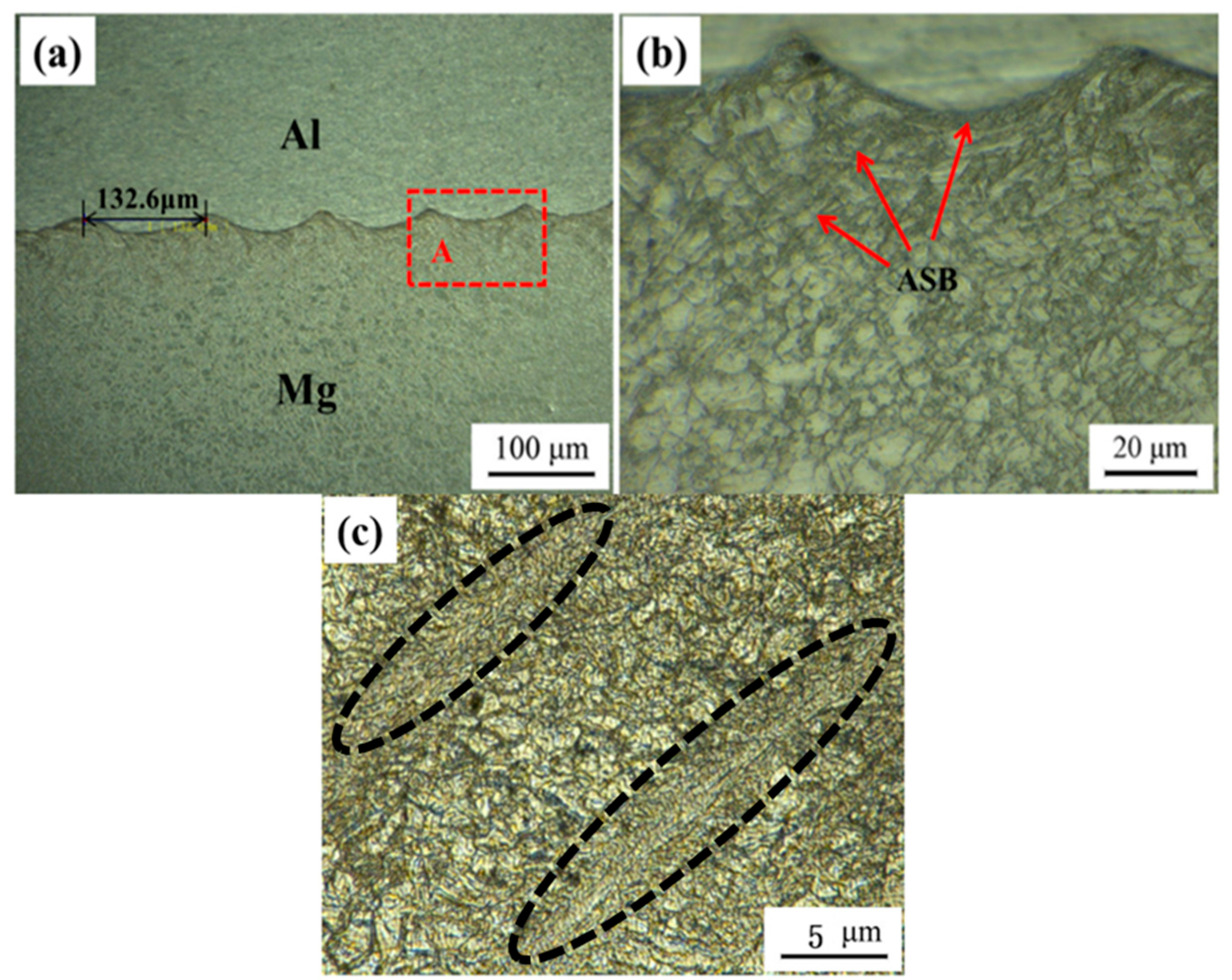
3.2. Microstructure of Welded Joints
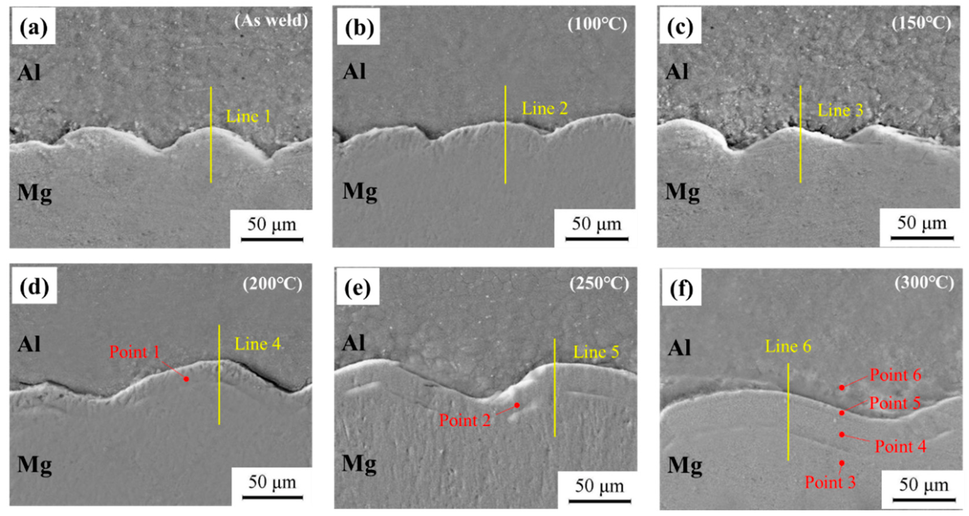
3.3. Influence of Temperature on Microstructure of Welded Joints
3.3.1. Microstructure Analysis of Welded Joints
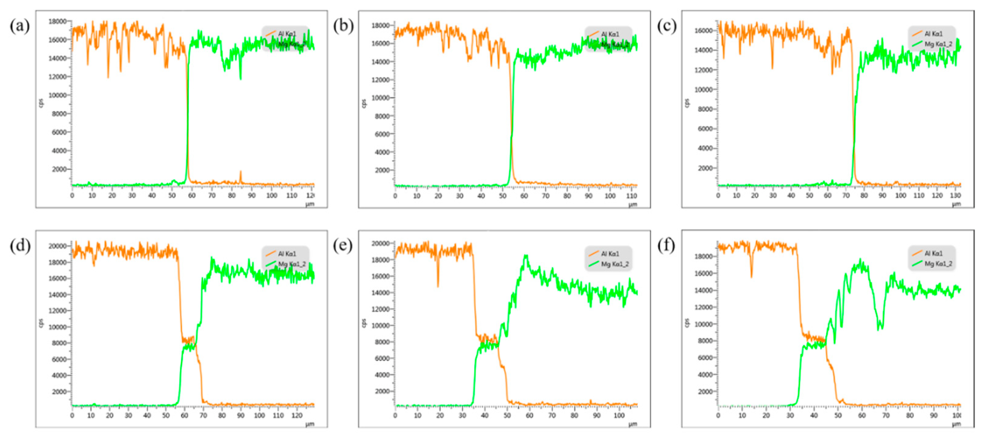
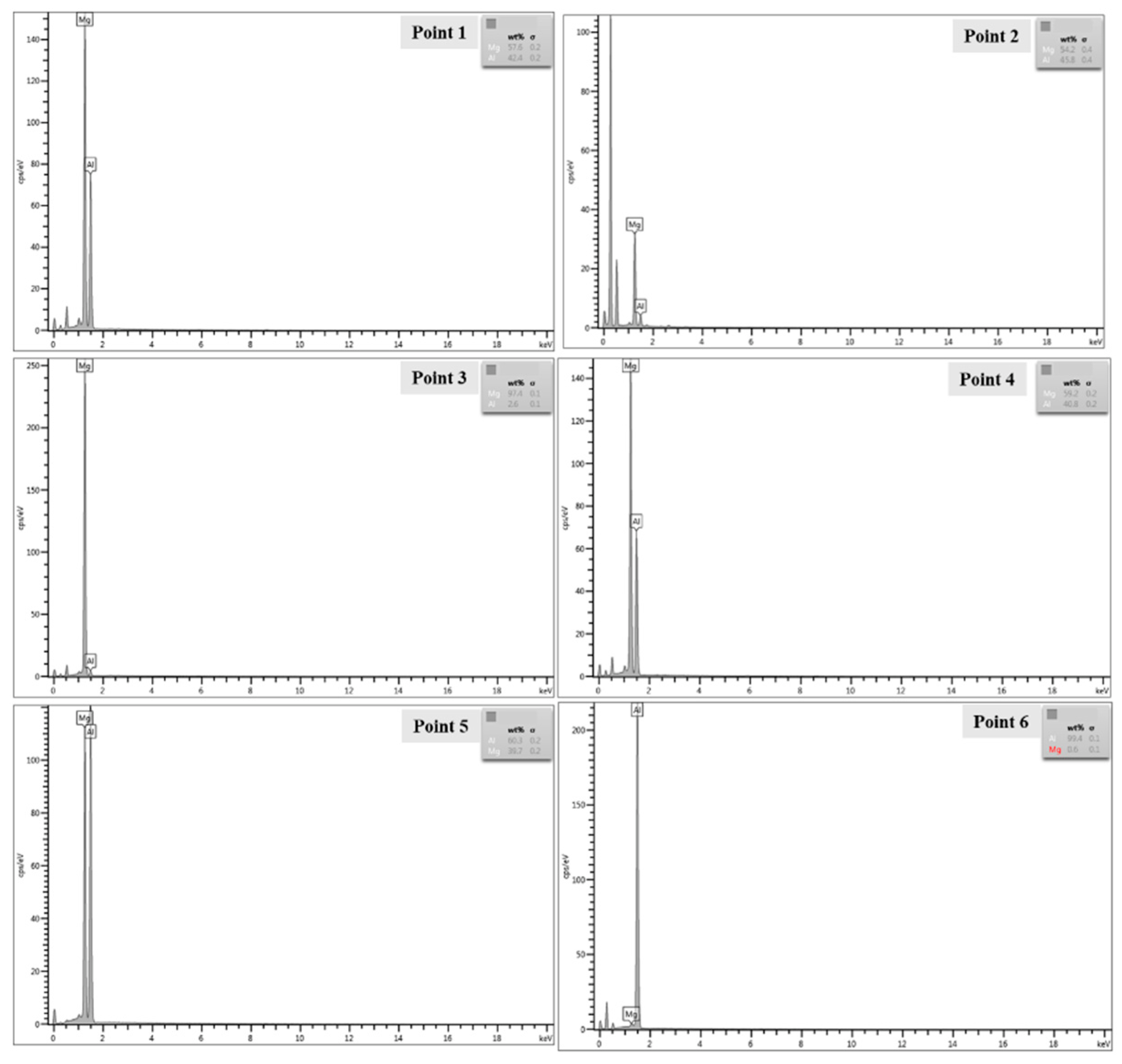
3.3.2. Component Analysis of Welded Joints
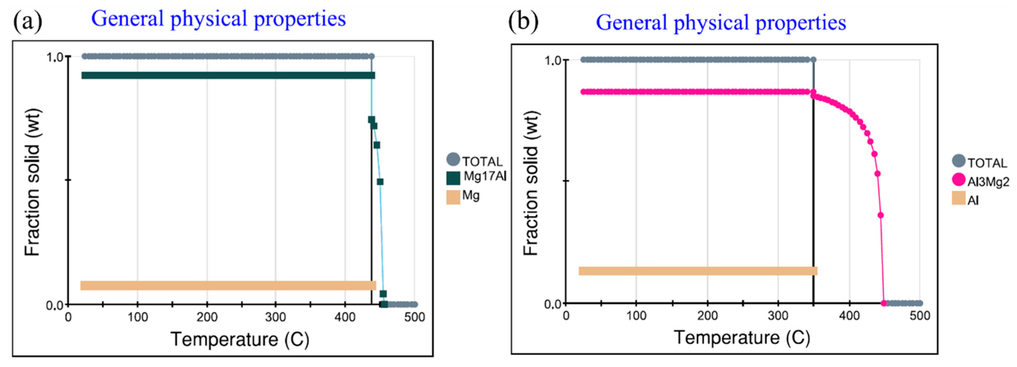
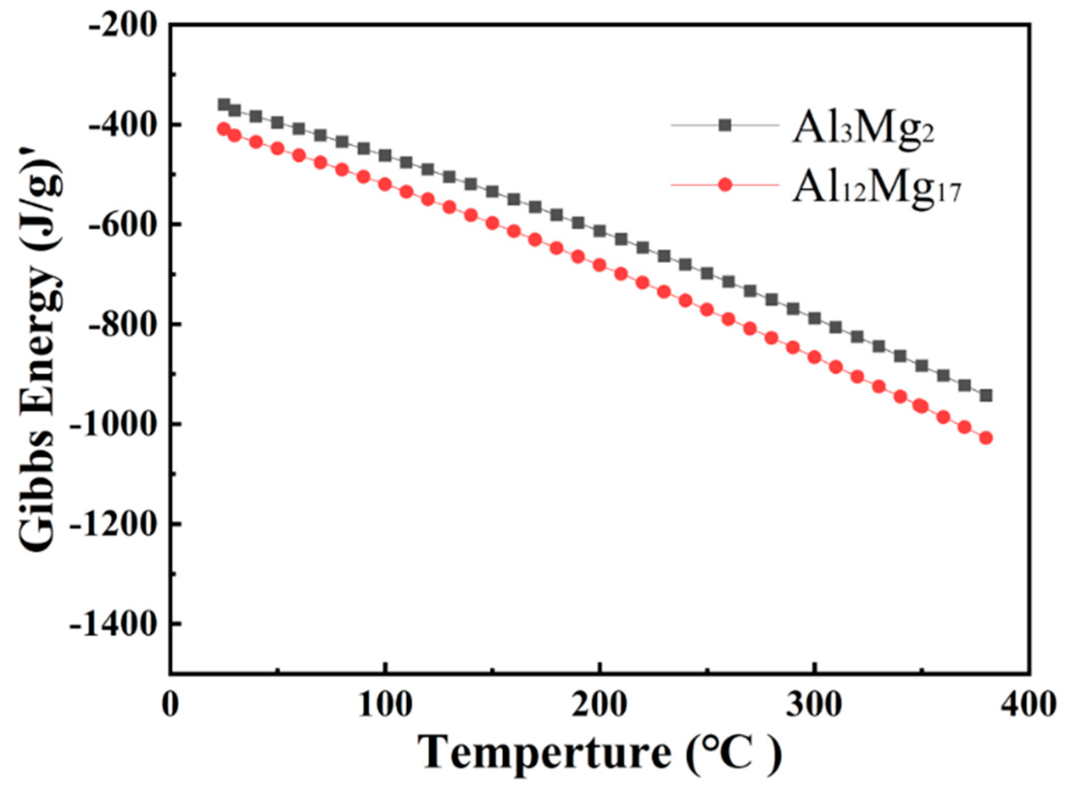
3.3.3. Thermodynamic Analysis of Welded Joints Microstructure
3.4. Influence of Temperature on Mechanical Properties of Welded Joints
3.4.1. Microhardness of Welded Joints
3.4.2. Tensile Shear Performance of Welded Joint
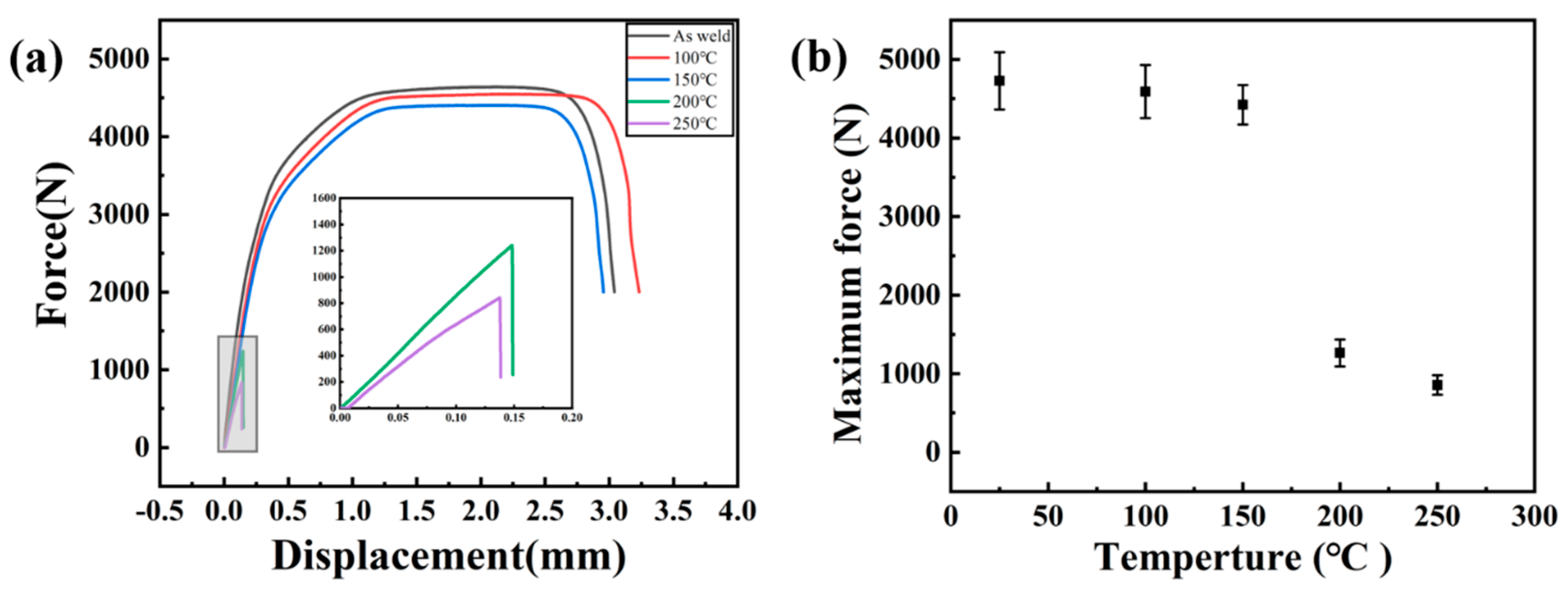
Tensile Shear Performance
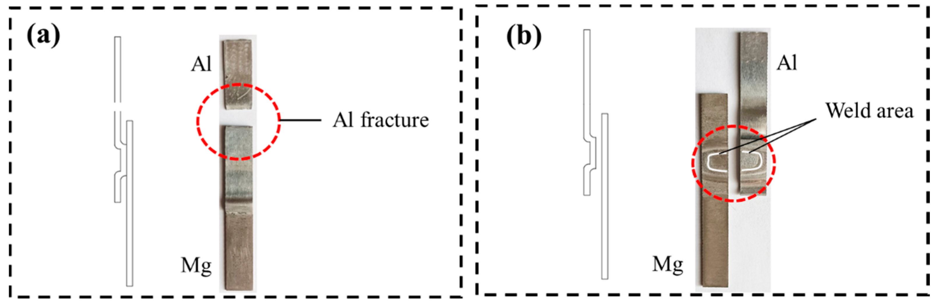
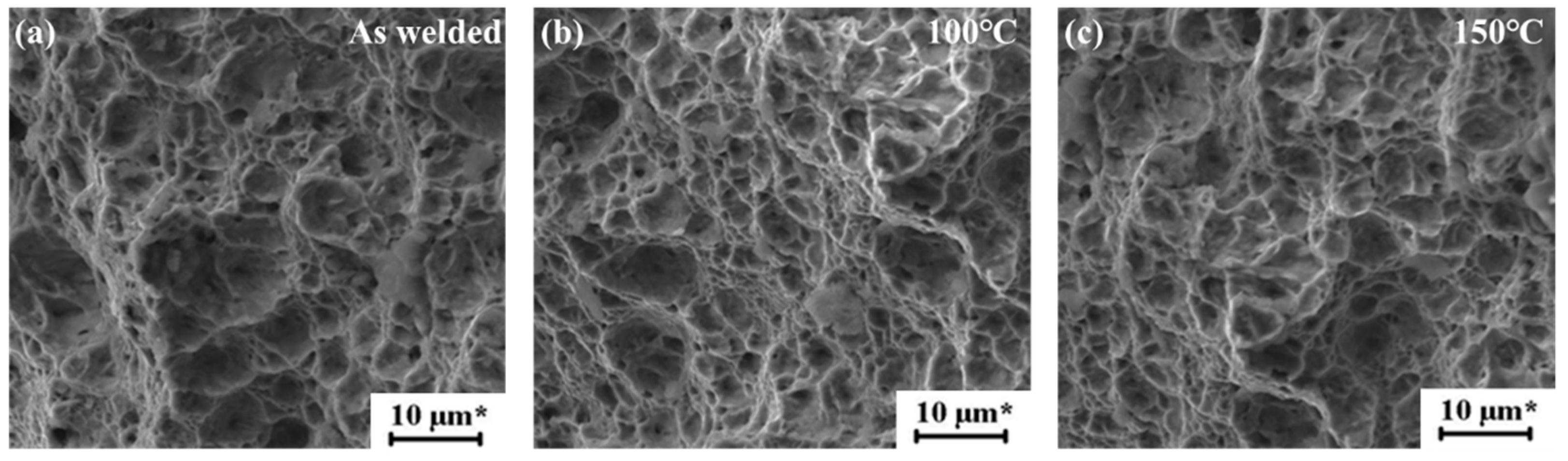
Fracture Analysis
4. Conclusions
- (1)
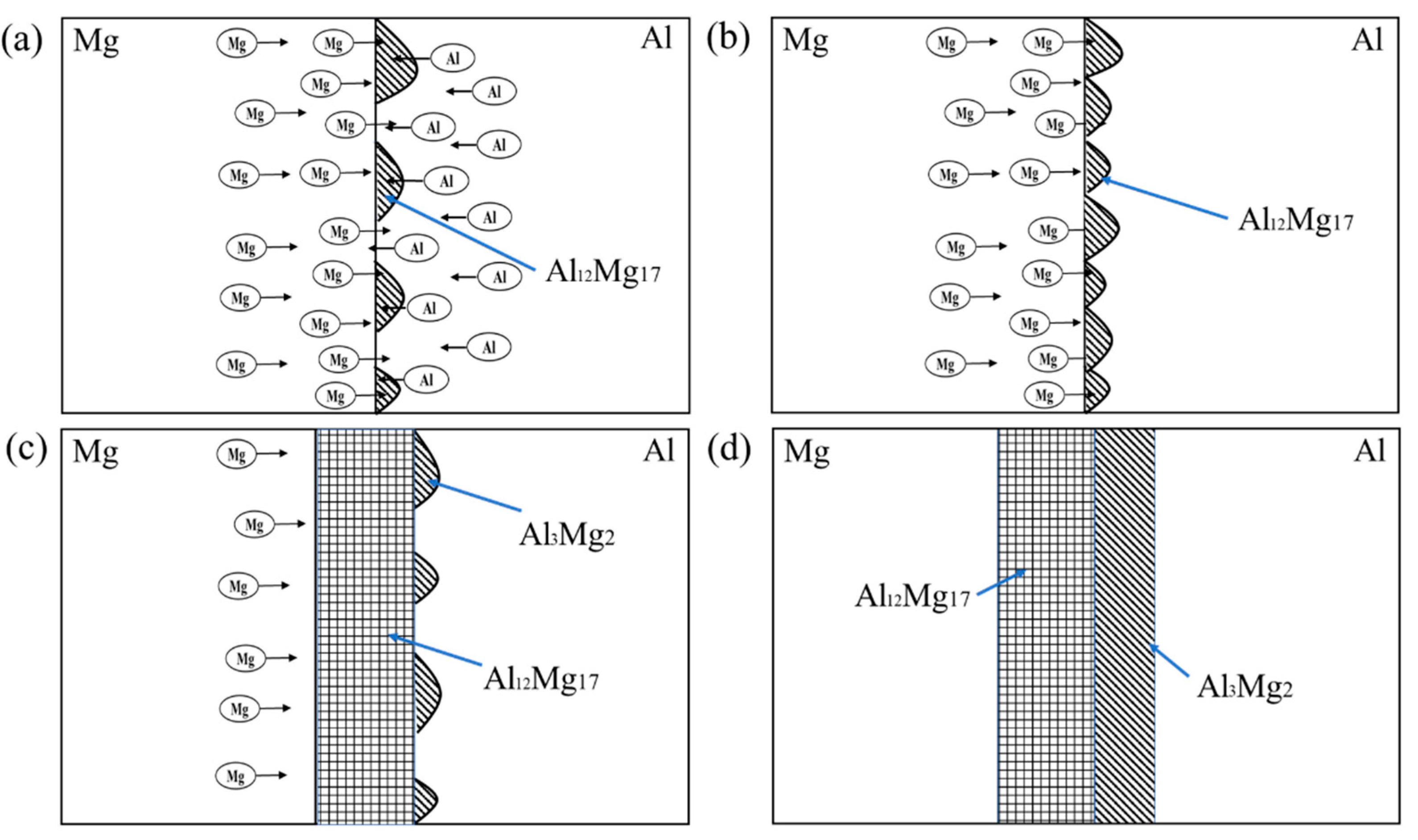
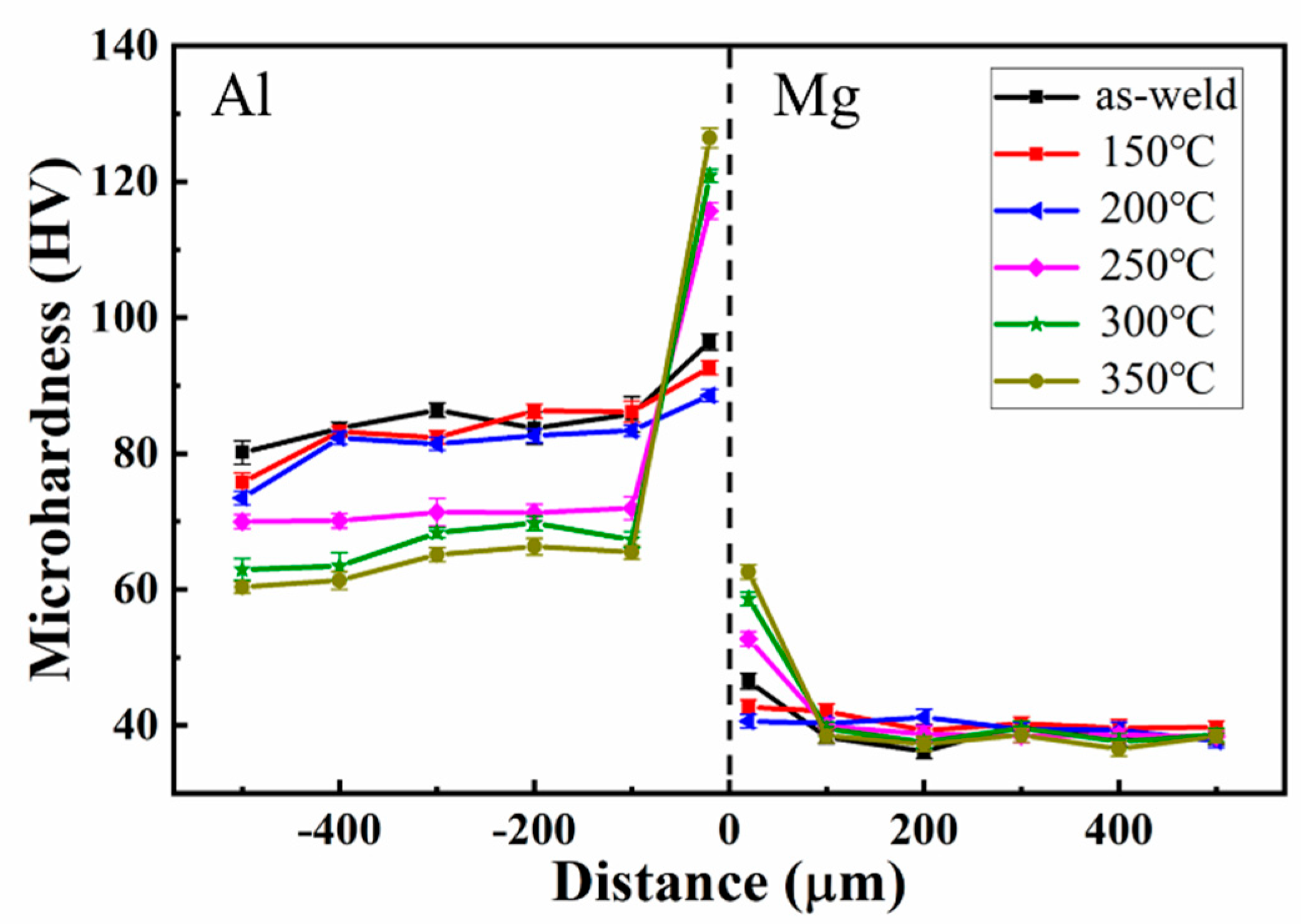
- Al-Mg magnetic pulse welding joint is a wavy bond, there are ASBs on the Mg side of the joints, Al and Mg elements diffuse each other on the interface, and the diffusion layer thickens obviously after thermal insulation treatment. At 200 °C, Al12Mg17 begins to grow on the welding interface. After the magnetic pulse welding is completed, the hardness of joints interface increases obviously. As the heat treatment temperature rises, the hardness of joints interface decreases first and then increases.
- (2)
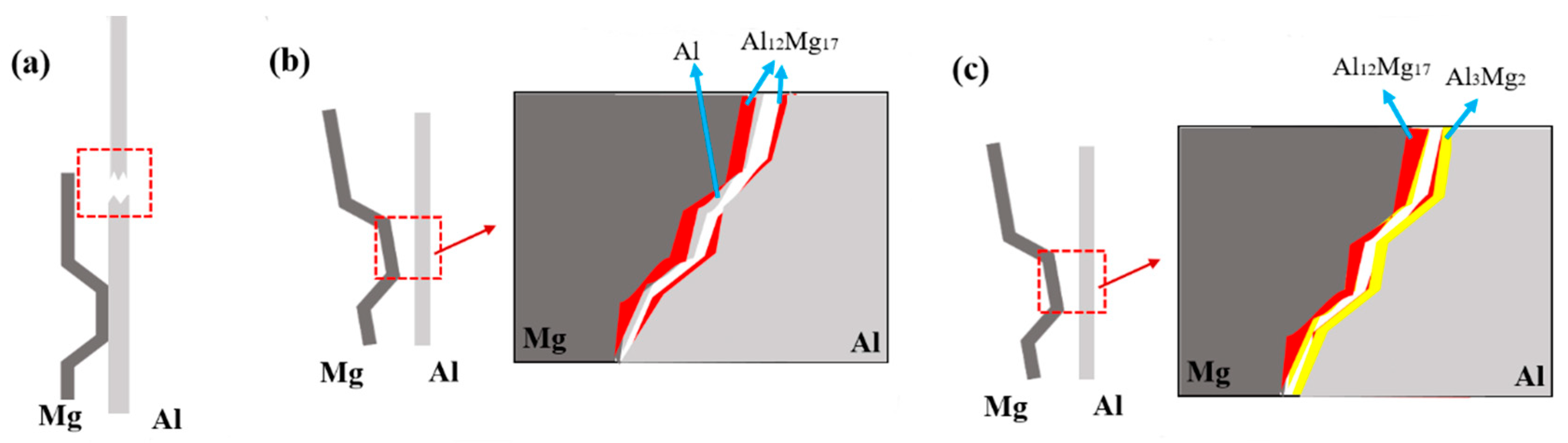
- Two intermetallic compounds, Al12Mg17 and Al3Mg2 are generated at the Al-Mg interface after holding at 300 °C. Al12Mg17 is generated at the Mg side first, and Al3Mg2 is generated at the Al side, forming the interface composition of Mg-Al12Mg17-Al3Mg2-Al.
- (3)
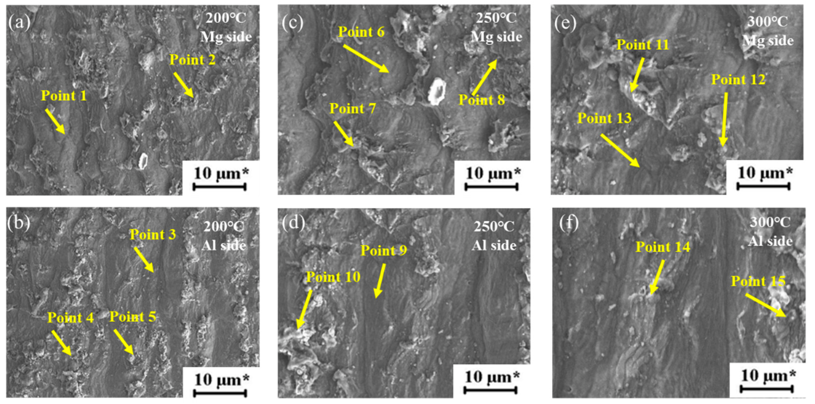
- In the tensile shear tests, Al-Mg magnetic pulse welded joints do not crack at 100 °C and 150 °C, but the 1060 Al base metal fracture occurs. At 200 °C and 250 °C, the joints fracture along the Al12Mg17-Al interface under tensile shear loads. After heat treatment at 300 °C, the joint cracks along the interface of Al12Mg17-Al3Mg2 intermetallic compounds under tensile and shear loads.
Author Contributions
Funding
Institutional Review Board Statement
Informed Consent Statement
Data Availability Statement
Conflicts of Interest
References
- Mohammadi, J.; Behnamian, Y.; Mostafaei, A.; Gerlich, A.P. Tool geometry, rotation and travel speeds effects on the properties of dissimilar magnesium/aluminum friction stir welded lap joints. Mater. Des. 2015, 75, 95–112. [Google Scholar] [CrossRef]
- Liu, L.; Ren, D.; Liu, F. A Review of Dissimilar Welding Techniques for Magnesium Alloys to Aluminum Alloys. Materials 2014, 7, 3735–3757. [Google Scholar] [CrossRef]
- Peng, H.; Chen, D.L.; Bai, X.F.; Wang, P.Q.; Li, D.Y.; Jiang, X.Q. Microstructure and mechanical properties of Mg-to-Al dissimilar welded joints with an Ag interlayer using ultrasonic spot welding. J. Magnes. Alloy. 2020, 8, 552–563. [Google Scholar] [CrossRef]
- Ben-Artzy, A.; Munitz, A.; Kohn, G.; Bronfin, B.; Shtechman, A. Joining of Light Hybrid Constructions Made of Magnesium and Aluminum Alloys. 2002, pp. 295–302. Available online: https://www.researchgate.net/publication/264845796_Joining_of_light_hybrid_constructions_made_of_magnesium_and_aluminum_alloys (accessed on 5 July 2022).
- Chen, S.; Jiang, X. Microstructure evolution during magnetic pulse welding of dissimilar aluminium and magnesium alloys. J. Manuf. Processes 2015, 19, 14–21. [Google Scholar] [CrossRef]
- Bataev, I.A.; Lazurenko, D.V.; Tanaka, S.; Hokamoto, K.; Bataev, A.A.; Guo, Y.; Jorge, A.M. High cooling rates and metastable phases at the interfaces of explosively welded materials high cooling rates and metastable phases at the interfaces of explosively welded materials. Acta Mater. 2017, 135, 277–289. [Google Scholar] [CrossRef]
- Stern, A.; Shribman, V.; Ben-Artzy, A.; Aizenshtein, M. Interface Phenomena and Bonding Mechanism in Magnetic Pulse Welding. J. Mater. Eng. Perform. 2014, 23, 3449–3458. [Google Scholar] [CrossRef]
- Kapil, A.; Sharma, A. Magnetic Pulse Welding: An efficient and environmentally friendly multi-material joining technique. J. Clean. Prod. 2015, 100, 35–58. [Google Scholar] [CrossRef]
- Zhu, C.; Sun, L.; Gao, W.; Li, G.; Cui, J. The effect of temperature on microstructure and mechanical properties of Al/Mg lap joints manufactured by magnetic pulse welding. J. Mater. Res. Technol. 2019, 8, 3270–3280. [Google Scholar] [CrossRef]
- Zhu, C.; Xu, S.; Gao, W.; Meng, Y.; Lin, S.; Dai, L. Microstructure characteristics and mechanical properties of Al/Mg joints manufactured by magnetic pulse welding. J. Magnes. Alloy. 2021, in press. [CrossRef]
- Ben-Artzy, A.; Stern, A.; Frage, N.; Shribman, V.; Sadot, O. Wave formation mechanism in magnetic pulse welding. Int. J. Impact Eng. 2010, 37, 397–404. [Google Scholar] [CrossRef]
- Casalino, G.; Ludovico, A.D. Finite element simulation of high speed pulse welding of high specific strength metal alloys. J. Mater. Process. Technol. 2008, 197, 301–305. [Google Scholar] [CrossRef]
- Xu, Z.; Cui, J.; Yu, H.; Li, C. Research on the impact velocity of magnetic impulse welding of pipe fitting. Mater. Des. 2013, 49, 736–745. [Google Scholar] [CrossRef]
- Shim, J.Y.; Kang, B.Y.; Kim, I.S.; Kang, M.J.; Kim, I.J. A Study on Distributions of Electromagnetic Force of the Dissimilar Metal Joining in MPW Using a FEM. Adv. Mater. Res. 2009, 83, 214–221. [Google Scholar] [CrossRef]
- Liu, Y.; Chen, Y.; Yu, K.Y.; Wang, H.; Chen, J.; Zhang, X. Stacking fault and partial dislocation dominated strengthening mechanisms in highly textured Cu/Co multilayers. Int. J. Plast. 2013, 49, 152–163. [Google Scholar] [CrossRef]
- Daghbouj, N.; Callisti, M.; Sen, H.S.; Karlik, M.; Polcar, T. Interphase boundary layer-dominated strain mechanisms in Cu+ implanted Zr-Nb nanoscale multilayers. Acta Mater. 2021, 202, 317–330. [Google Scholar] [CrossRef]
- Daghbouj, N.; Sen, H.S.; Callisti, M.; Vronka, M.; Karlik, M.; Duchoň, J.; Ech, J.; Havránek, V.; Polcar, T. Revealing Nanoscale Strain Mechanisms in Ion-Irradiated Multilayers. Acta Mater. 2022, 229, 117807. [Google Scholar] [CrossRef]
- Daghbouj, N.; Li, B.S.; Callisti, M.; Sen, H.S.; Polcar, T. Microstructural evolution of helium-implanted 6H-SiC subjected to different irradiation conditions and annealing temperatures: A multiple characterization study. Acta Mater. 2019, 181, 160–172. [Google Scholar] [CrossRef]
- Zhu, C.C.; Meng, Y.F.; Liu, Q.X.X.; Li, G.Y.; Cui, J.J. Study on Process and Mechanical Properties of Al/Mg Dissimilar Metal Sheet Joints by Magnetic Pulse Welding. J. Netshape Form. Eng. 2021, 13, 7. [Google Scholar]
- Li, Y.; Liu, C.; Yu, H.; Zhao, F.; Wu, Z. Numerical Simulation of Ti/Al Bimetal Composite Fabricated by Explosive Welding. Metals 2017, 7, 407. [Google Scholar] [CrossRef]
- Zhou, Y.; Li, C.X.; Du, J.; Wang, X.M.; Yao, C.G. Investigation on the Effect of Discharge Voltage on Metal Jet and Bonded Interface in Mg-Al Magnetic Pulse Welding. Trans. China Electrotech. Soc. 2022, 37, 11. [Google Scholar]
- Cui, J.; Sun, G.; Li, G.; Xu, Z.; Chu, P.K. Specific wave interface and its formation during magnetic pulse welding. Appl. Phys. Lett. 2014, 105, 2588. [Google Scholar] [CrossRef]
- Wronka, B. Testing of explosive welding and welded joints. The microstructure of explosive welded joints and their mechanical properties. J. Mater. Sci. 2010, 45, 3465–3469. [Google Scholar] [CrossRef]
- Zhang, N.; Wang, W.; Cao, X.; Wu, J. The effect of annealing on the interface microstructure and mechanical characteristics of AZ31B/AA6061 composite plates fabricated by explosive welding. Mater. Des. 2015, 65, 1100–1109. [Google Scholar] [CrossRef]
- Zhang, T.; Wang, W.; Zhang, W.; Wei, Y.; Cao, X.; Yan, Z.; Zhou, J. Microstructure evolution and mechanical properties of an AA6061/AZ31B alloy plate fabricated by explosive welding. J. Alloy. Compd. 2017, 735, 1759–1768. [Google Scholar] [CrossRef]
- Mousavi, S.; Al-Hassani, S.; Atkins, A.G. Bond strength of explosively welded specimens. Mater. Des. 2008, 29, 1334–1352. [Google Scholar] [CrossRef]
- Acarer, M.; Demir, B. An investigation of mechanical and metallurgical properties of explosive welded aluminum–dual phase steel. Mater. Lett. 2008, 62, 4158–4160. [Google Scholar] [CrossRef]
- Li, Y.; Wu, Z. Microstructural Characteristics and Mechanical Properties of 2205/AZ31B Laminates Fabricated by Explosive Welding. Metals 2017, 7, 125. [Google Scholar] [CrossRef]
- Hu, G.; Cai, X.; Rong, Y.H. Fundamentals of Materials Science; Shanghai Jiao Tong University Press: Shanghai, China, 2010. [Google Scholar]
- Firouzdor, V.; Kou, S. Formation of Liquid and Intermetallics in Al-to-Mg Friction Stir Welding. Metall. Mater. Trans. A 2010, 41, 3238–3251. [Google Scholar] [CrossRef]
- Macwan, A.; Jiang, X.Q.; Li, C.; Chen, D.L. Effect of annealing on interface microstructures and tensile properties of rolled Al/Mg/Al tri-layer clad sheets. Mater. Sci. Eng. A 2013, 587, 344–351. [Google Scholar] [CrossRef]
- Yong, D.; Chang, Y.A.; Huang, B.; Gong, W.; Jin, Z.; Xu, H.; Yuan, Z.; Liu, Y.; He, Y.; Xie, F.Y. Diffusion coefficients of some solutes in fcc and liquid Al: Critical evaluation and correlation. Mater. Sci. Eng. A 2003, 363, 140–151. [Google Scholar]
- Honarpisheh, M.; Asemabadi, M.; Sedighi, M. Investigation of annealing treatment on the interfacial properties of explosive-welded Al/Cu/Al multilayer. Mater. Des. 2012, 37, 122–127. [Google Scholar] [CrossRef]


| Material | Al | Mg | Si | Zn | Mn | Fe | Cu | Ti | Ca | Ni |
|---|---|---|---|---|---|---|---|---|---|---|
| 1060 Al | 99.6 | 0.03 | 0.25 | 0.05 | 0.03 | 0.35 | 0.05 | 0.03 | ||
| AZ31B Mg | 2.5–3.5 | Bal. | 0.08 | 0.6–1.4 | 0.2–1.0 | 0.003 | 0.04 | 0.04 | 0.001 |
| Point | Al (at.%) | Mg (at.%) | Material |
|---|---|---|---|
| Point 1 | 42.4 | 57.6 | Al12Mg17 |
| Point 2 | 45.8 | 54.2 | Al12Mg17 |
| Point 3 | 2.6 | 97.4 | AZ31B |
| Point 4 | 40.8 | 59.2 | Al12Mg17 |
| Point 5 | 60.3 | 39.7 | Al3Mg2 |
| Point 6 | 99.4 | 0.6 | 1060Al |
| Elements | Diffusion Coefficient (m2/s) | Diffusion Activation Energy (J/mol) |
|---|---|---|
| Al | 1.7 × 10⁻⁴ | 1.42 × 10⁵ |
| Mg | 1.5 × 10⁻⁴ | 1.35 × 10⁵ |
| Point | 1 | 2 | 3 | 4 | 5 | 6 | 7 | 8 |
|---|---|---|---|---|---|---|---|---|
| Al (at.%) | 100 | 41.4 | 100 | 40.9 | 41.8 | 100 | 42.2 | 40.7 |
| Mg (at.%) | / | 58.6 | / | 59.1 | 58.2 | / | 57.8 | 59.3 |
| Point | 9 | 10 | 11 | 12 | 13 | 14 | 15 | |
| Al (at.%) | 100 | 42.5 | 40.6 | 41.9 | 61.8 | 59.7 | 60.5 | |
| Mg (at.%) | / | 57.5 | 59.4 | 58.1 | 38.2 | 40.3 | 39.5 |
Publisher’s Note: MDPI stays neutral with regard to jurisdictional claims in published maps and institutional affiliations. |
© 2022 by the authors. Licensee MDPI, Basel, Switzerland. This article is an open access article distributed under the terms and conditions of the Creative Commons Attribution (CC BY) license (https://creativecommons.org/licenses/by/4.0/).
Share and Cite
Li, Y.; Yang, D.; Yang, W.; Wu, Z.; Liu, C. Effect of Annealing Temperature on Microstructure and Properties of Al/Mg Magnetic Pulse Welding Joints. Materials 2022, 15, 5519. https://doi.org/10.3390/ma15165519
Li Y, Yang D, Yang W, Wu Z, Liu C. Effect of Annealing Temperature on Microstructure and Properties of Al/Mg Magnetic Pulse Welding Joints. Materials. 2022; 15(16):5519. https://doi.org/10.3390/ma15165519
Chicago/Turabian StyleLi, Yan, Dezhi Yang, Wenyu Yang, Zhisheng Wu, and Cuirong Liu. 2022. "Effect of Annealing Temperature on Microstructure and Properties of Al/Mg Magnetic Pulse Welding Joints" Materials 15, no. 16: 5519. https://doi.org/10.3390/ma15165519
APA StyleLi, Y., Yang, D., Yang, W., Wu, Z., & Liu, C. (2022). Effect of Annealing Temperature on Microstructure and Properties of Al/Mg Magnetic Pulse Welding Joints. Materials, 15(16), 5519. https://doi.org/10.3390/ma15165519