
Analytical Model of Hole Diameter and Self-Guiding Machining Mechanism of BTA Deep Hole Drilling


Abstract
:1. Introduction
2. Methodology
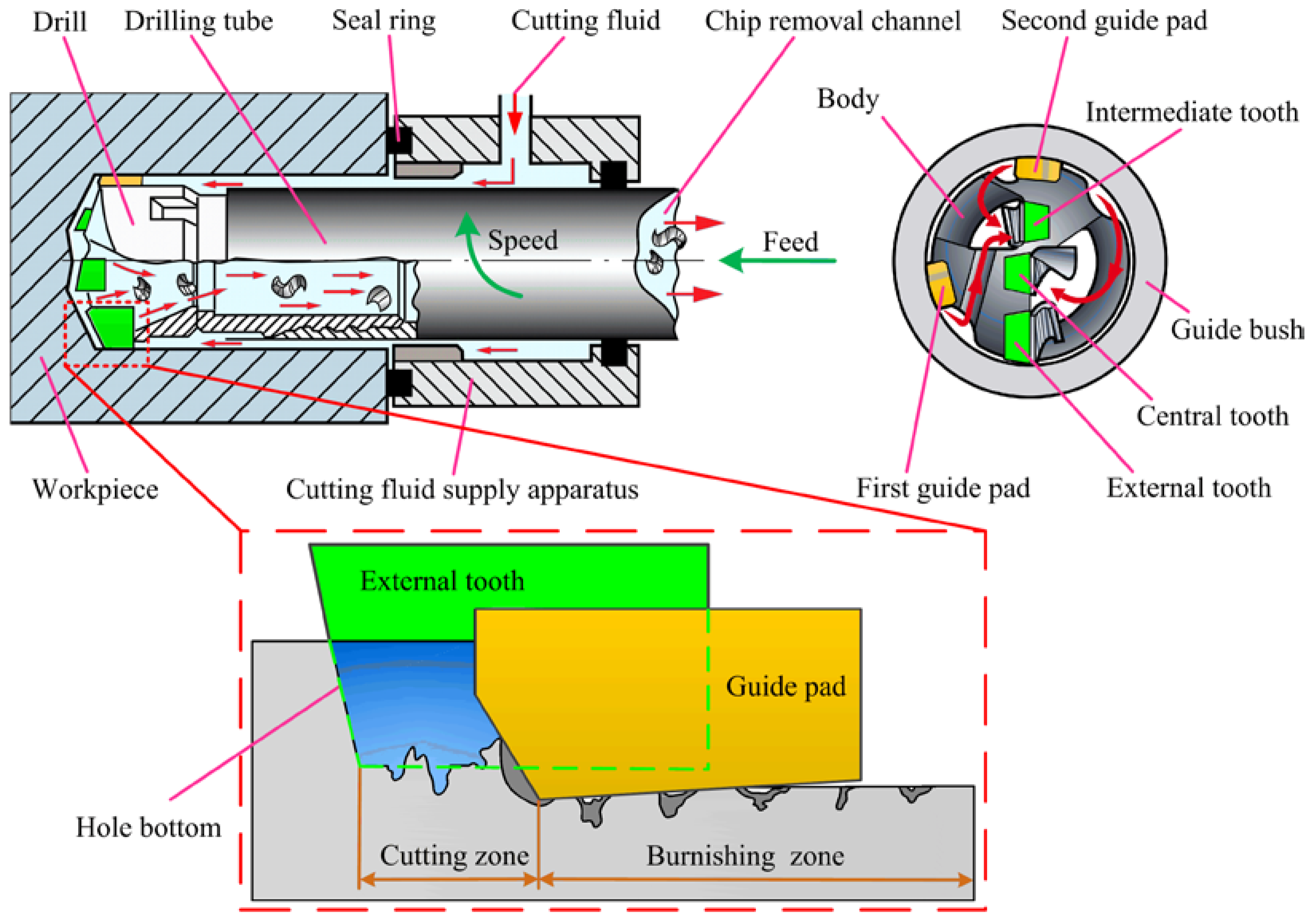
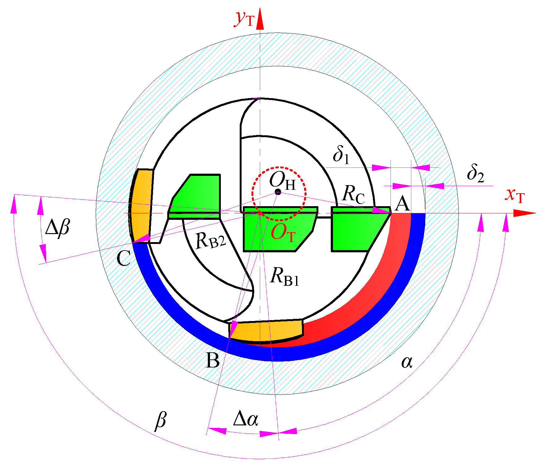
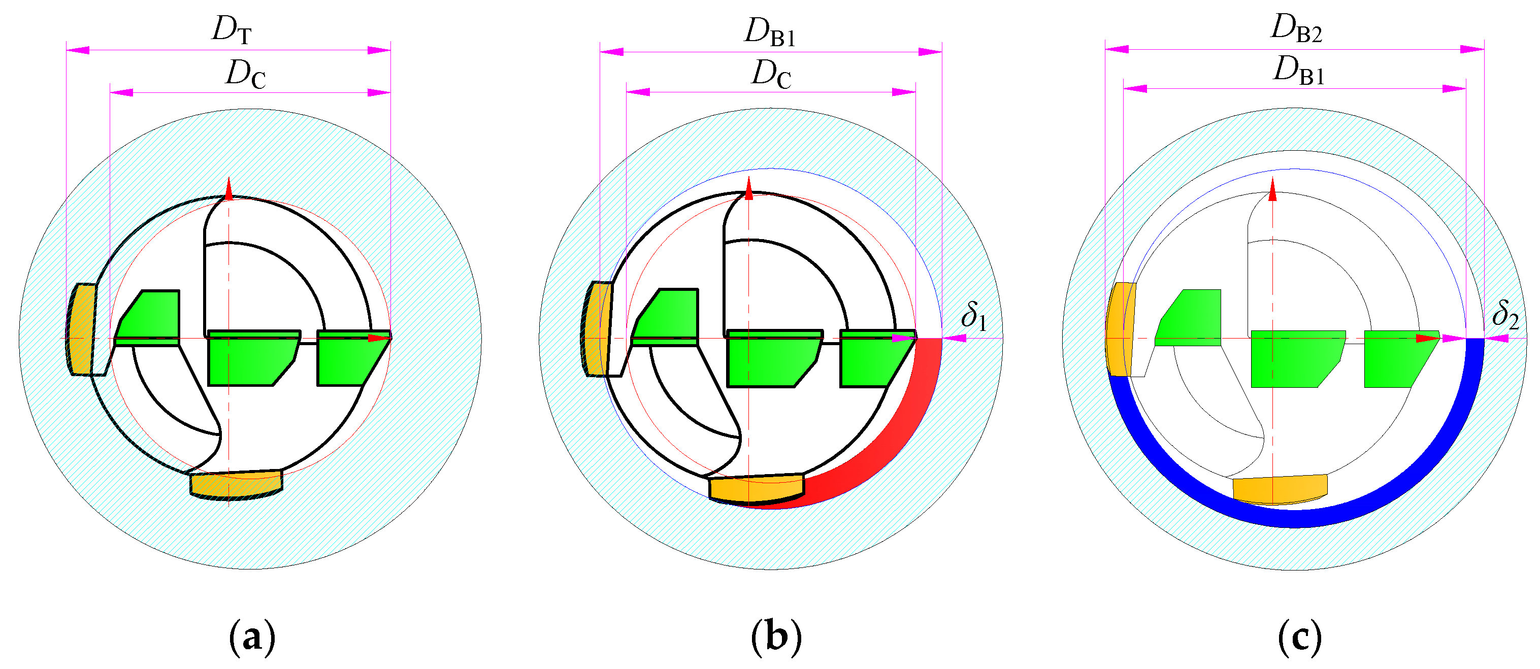
2.1. Hole-Forming Mechanism
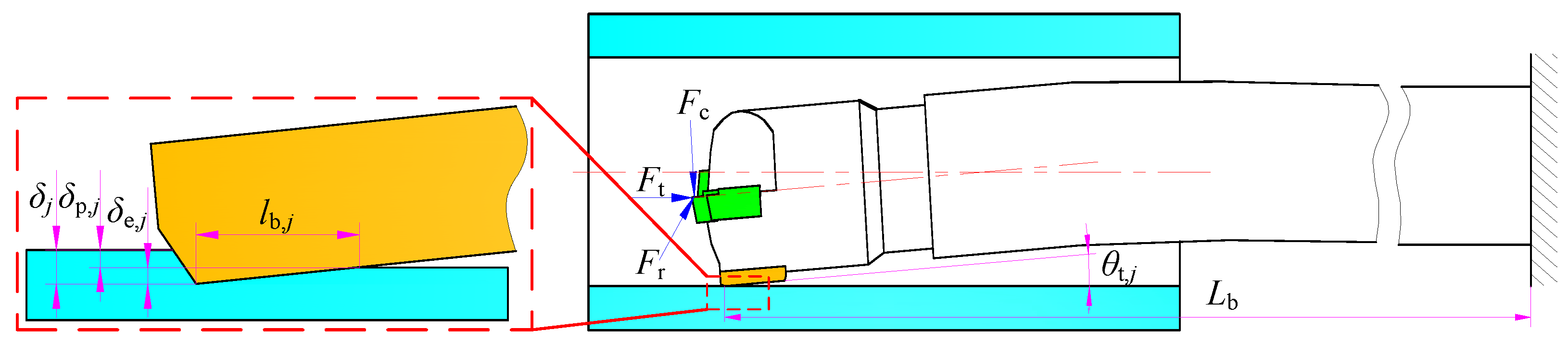
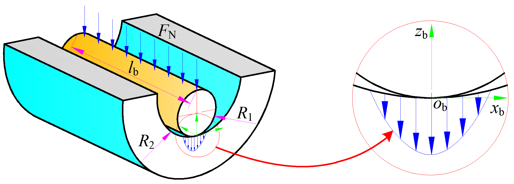
2.2. Extrusion Deformation
3. Simulation
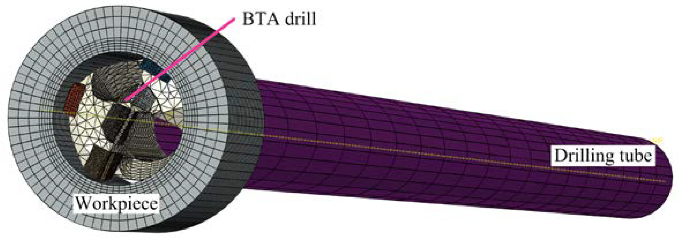
3.1. FEM Model
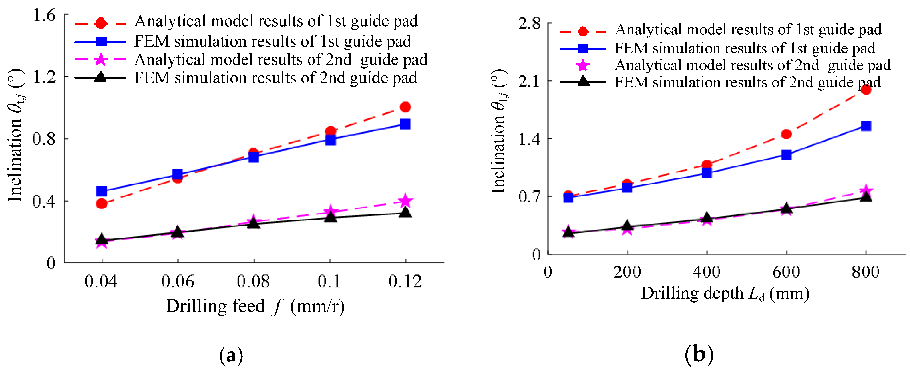
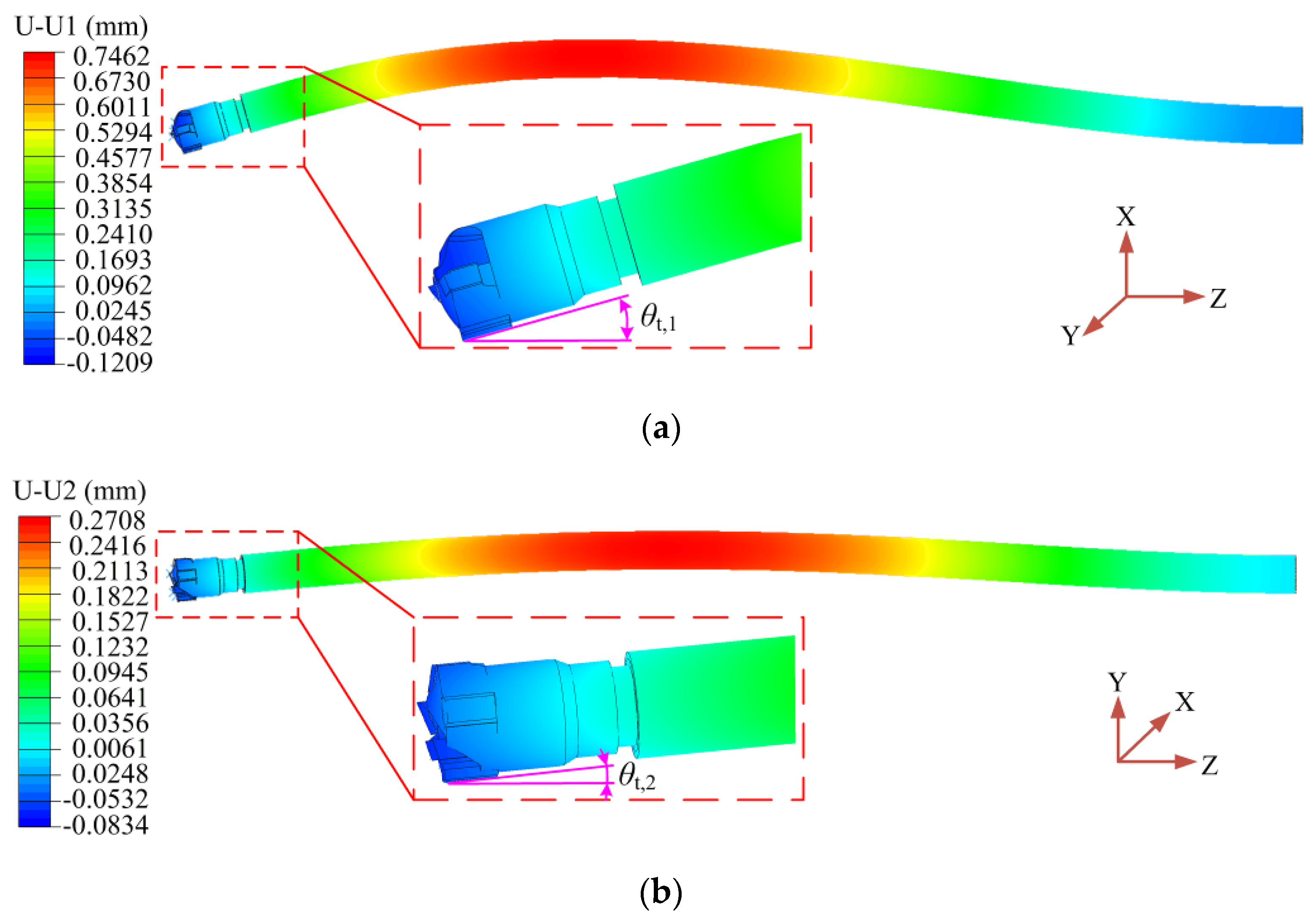
3.2. Contact Inclination Angle
3.3. Contact Stress
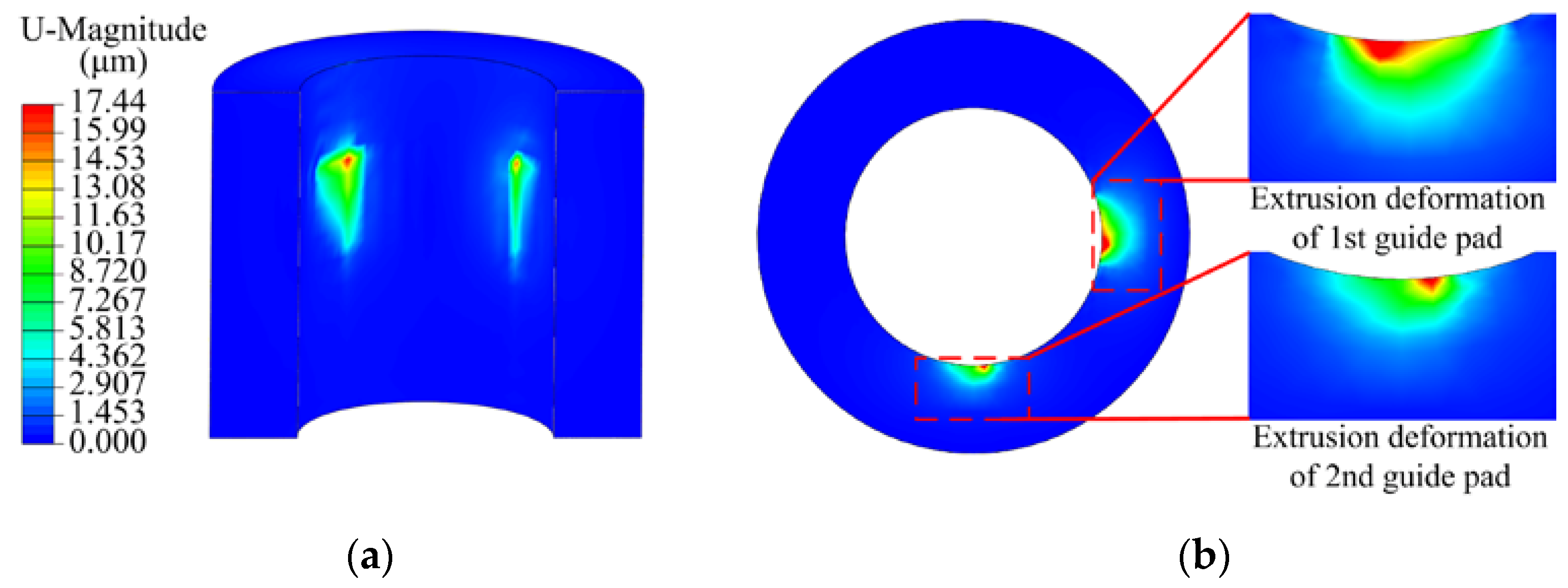
3.4. Contact Deformation
4. Verification and Discussion
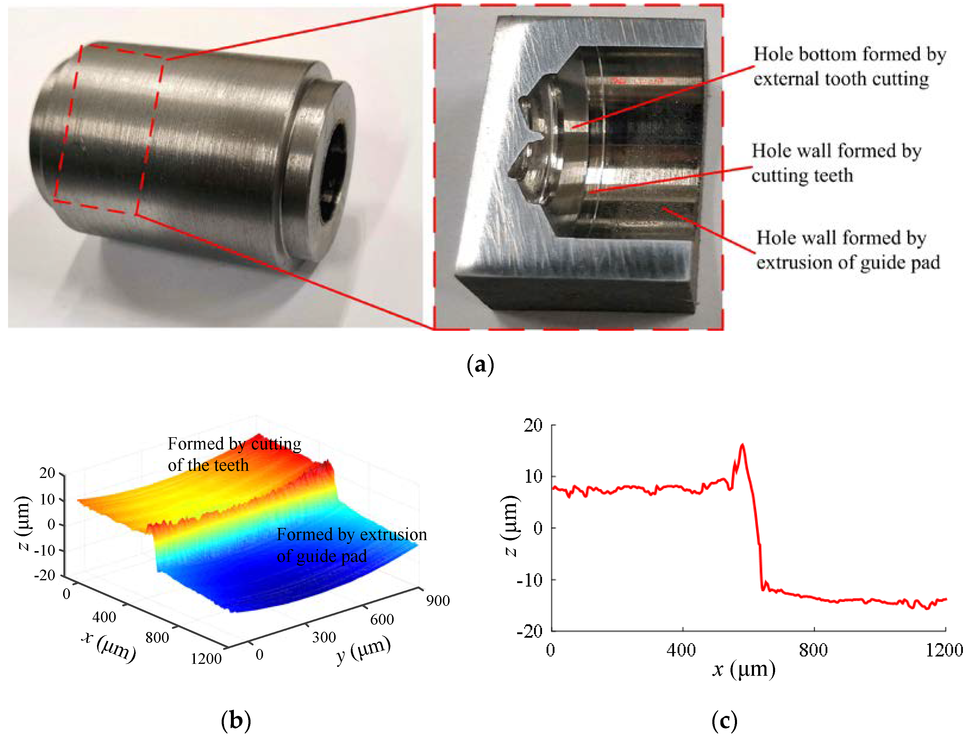
4.1. Experimental Equipment
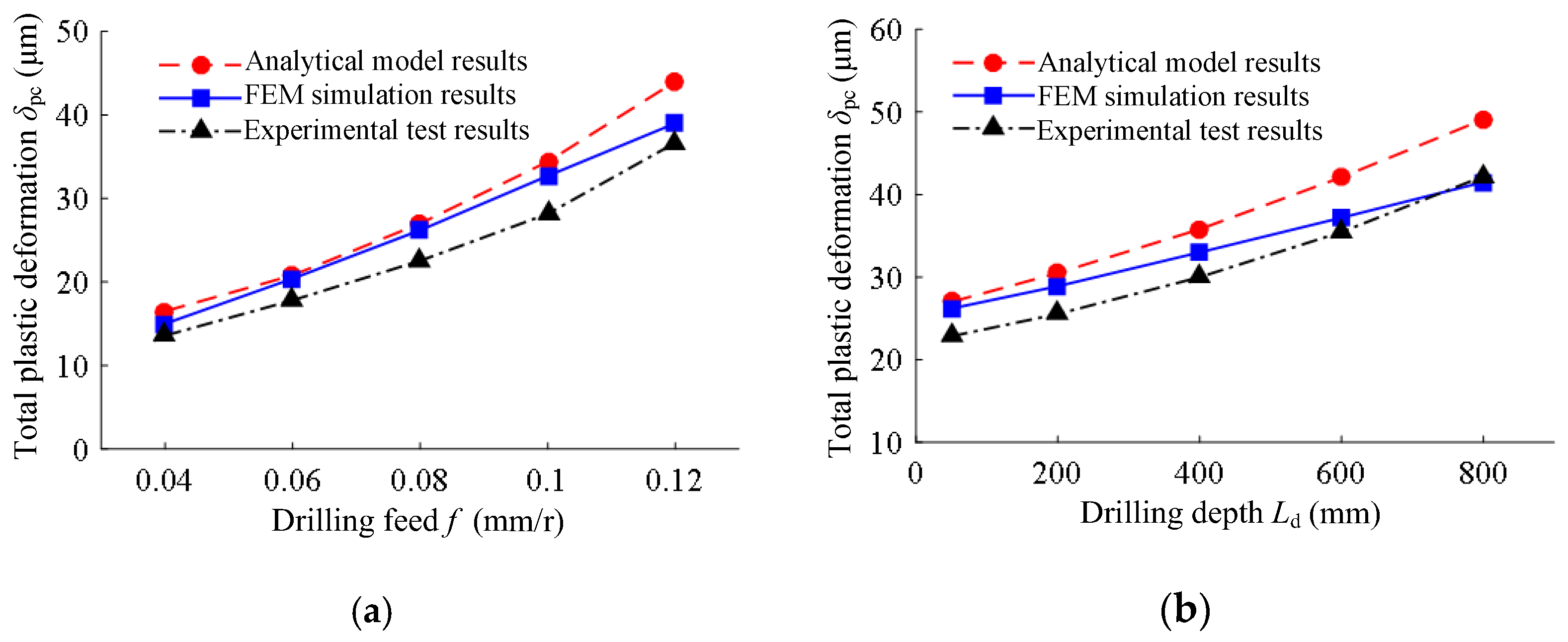
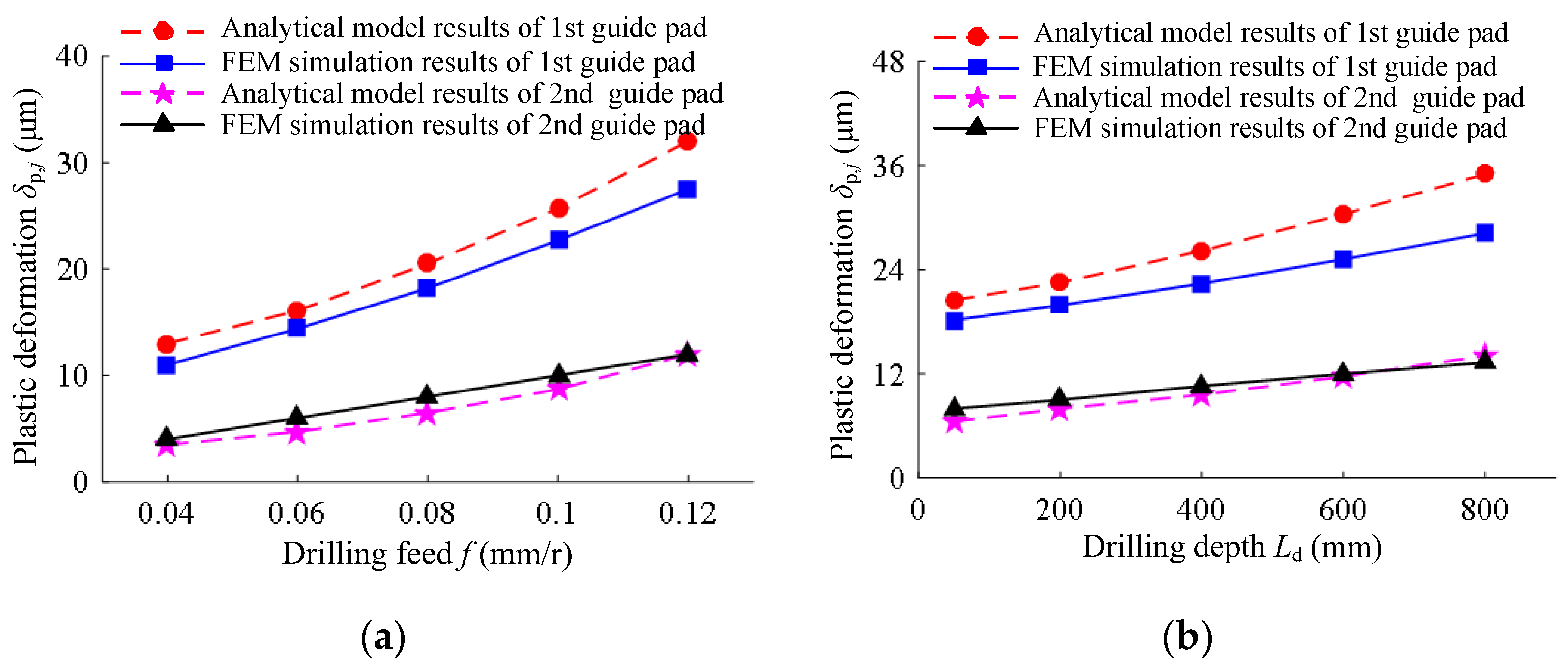
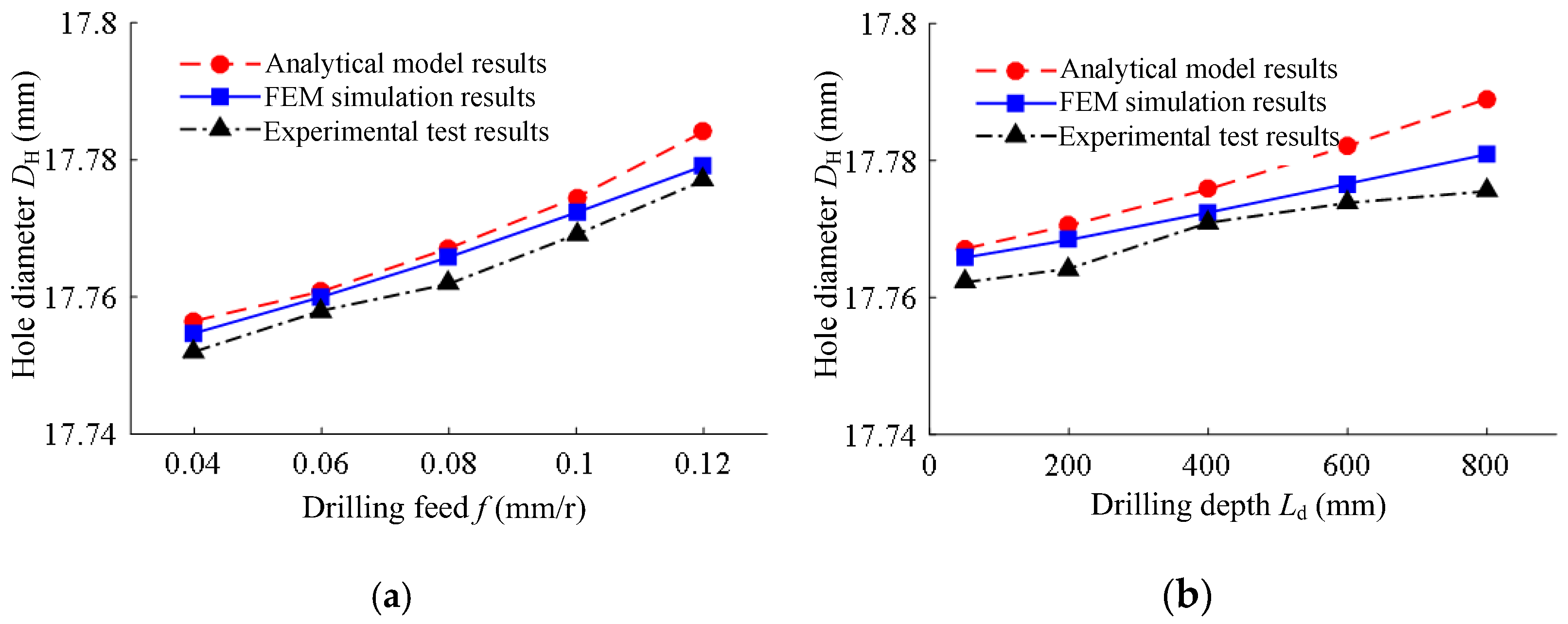
4.2. Model Validation
5. Conclusions
Author Contributions
Funding
Institutional Review Board Statement
Informed Consent Statement
Data Availability Statement
Acknowledgments
Conflicts of Interest
References
- Si, Y.; Kong, L.; Chin, J.-H.; Guo, W.; Wang, Q. Whirling detection in deep hole drilling process based on multivariate synchrosqueezing transform of orthogonal dual-channel vibration signals. Mech. Syst. Signal Process. 2021, 167, 108621. [Google Scholar] [CrossRef]
- Feng, Y.; Zheng, H.; Han, X.; Liu, Z. Multiobjective Optimization of Cutting Parameters for TA10 Alloy Deep-Hole Drilling. Materials 2022, 15, 4366. [Google Scholar] [CrossRef] [PubMed]
- Lew, M.; Chaudhari, A.; Neo, W.K.; Kumar, S.; Amrun, M.; Rashid, M.A.; Rahman, M. Modeling of dynamic behavior of multispan gundrilling shaft with coolant and its effect on straightness deviation. CIRP J. Manuf. Sci. Technol. 2020, 29, 11–24. [Google Scholar] [CrossRef]
- Li, X.-B.; Zheng, J.-M.; Li, Y.; Kong, L.-F.; Shi, W.-C.; Guo, B. Investigation of Chip Deformation and Breaking with a Staggered Teeth BTA Tool in Deep Hole Drilling. Metals 2019, 9, 46. [Google Scholar] [CrossRef] [Green Version]
- Zhang, H.; Shen, X.; Bo, A.; Li, Y.; Zhan, H.; Gu, Y. A multiscale evaluation of the surface integrity in boring trepanning association deep hole drilling. Int. J. Mach. Tools Manuf. 2017, 123, 48–56. [Google Scholar] [CrossRef]
- Haddag, B.; Nouari, M.; Moufki, A. Experimental analysis of the BTA deep drilling and a new analytical thermomechanical model for assessment of cutting forces and BTA drill design. Int. J. Adv. Manuf. Technol. 2019, 106, 455–469. [Google Scholar] [CrossRef]
- Malarvizhi, S.; Chaudhari, A.; Woon, K.S.; Kumar, A.S.; Rahman, M. Influence of Burnishing Axial Interference on Hole Surface Quality in Deep Hole Drilling of Inconel 718. Procedia Manuf. 2016, 5, 1295–1307. [Google Scholar] [CrossRef] [Green Version]
- Bleicher, F.; Reiter, M.; Brier, J. Increase of chip removal rate in single-lip deep hole drilling at small diameters by low-frequency vibration support. CIRP Ann. 2019, 68, 93–96. [Google Scholar] [CrossRef]
- Ahmed, A.; Lew, M.; Diwakar, P.; Kumar, A.S.; Rahman, M. A novel approach in high performance deep hole drilling of Inconel 718. Precis. Eng. 2019, 56, 432–437. [Google Scholar] [CrossRef]
- Yu, D. Self-centering positioner and principle for locating and guiding deep-hole drills using oil films. Int. J. Adv. Manuf. Technol. 2017, 92, 639–649. [Google Scholar] [CrossRef]
- Si, Y.; Zhang, Z.; Kong, L.; Zheng, J. Condition monitoring of deep-hole drilling process based on improved empirical wavelet de-noising and high multiple frequency components of rotation frequency. Int. J. Adv. Manuf. Technol. 2021, 114, 2201–2214. [Google Scholar] [CrossRef]
- Kong, L.; Cao, S.; Chin, J.-H.; Si, Y.; Miao, F.; Li, Y. Vibration suppression of drilling tool system during deep-hole drilling process using independence mode space control. Int. J. Mach. Tools Manuf. 2020, 151, 103525. [Google Scholar] [CrossRef]
- Tnay, G.; Wan, S.; Woon, K.; Yeo, S. The effects of dub-off angle on chip evacuation in single-lip deep hole gun drilling. Int. J. Mach. Tools Manuf. 2016, 108, 66–73. [Google Scholar] [CrossRef]
- Zhang, X.; Tnay, G.L.; Liu, K.; Kumar, A.S. Effect of apex offset inconsistency on hole straightness deviation in deep hole gun drilling of Inconel 718. Int. J. Mach. Tools Manuf. 2018, 125, 123–132. [Google Scholar] [CrossRef]
- Richardson, R.; Bhatti, R. A review of research into the role of guide pads in BTA deep-hole machining. J. Mater. Process. Technol. 2001, 110, 61–69. [Google Scholar] [CrossRef]
- Biermann, D.; Bleicher, F.; Heisel, U.; Klocke, F.; Möhring, H.-C.; Shih, A. Deep hole drilling. CIRP Ann. 2018, 67, 673–694. [Google Scholar] [CrossRef]
- Woon, K.; Chaudhari, A.; Rahman, M.; Wan, S.; Kumar, A.S. The effects of tool edge radius on drill deflection and hole misalignment in deep hole gundrilling of Inconel-718. CIRP Ann. 2014, 63, 125–128. [Google Scholar] [CrossRef]
- Zhang, H.; Shen, X.; Li, Y.; Yang, F.; Kwon, P.; Zhang, D.; Zi, B.; Cui, G.; Ding, H. The Effects of Guide Pads on Bore Diameter Enlargement Magnitude in Deep Hole Drilling. MATEC Web Conf. 2016, 77, 1021. [Google Scholar] [CrossRef] [Green Version]
- Felinks, N.; Rinschede, T.; Biermann, D.; Stangier, D.; Tillmann, W.; Fuß, M.; Abrahams, H. Investigation into deep hole drilling of austenitic steel with advanced tool solutions. Int. J. Adv. Manuf. Technol. 2021, 118, 1087–1100. [Google Scholar] [CrossRef]
- Neo, D.W.K.; Liu, K.; Kumar, A.S. High throughput deep-hole drilling of Inconel 718 using PCBN gun drill. J. Manuf. Process. 2020, 57, 302–311. [Google Scholar] [CrossRef]
- Yang, S.; Tong, X.; Ma, X.; Ji, W.; Liu, X.; Zhang, Y. The guide block structure design of boring and trepanning association (BTA) deep hole drilling. Int. J. Adv. Manuf. Technol. 2018, 99, 911–918. [Google Scholar] [CrossRef]
- Astakhov, V.; Osman, M. An analytical evaluation of the cutting forces in self-piloting drilling using the model of shear zone with parallel boundaries. Part 1: Theory. Int. J. Mach. Tools Manuf. 1996, 36, 1187–1200. [Google Scholar] [CrossRef]
- Astakhov, V.; Osman, M. An analytical evaluation of the cutting forces in self-piloting drilling using the model of shear zone with parallel boundaries. Part 2: Application. Int. J. Mach. Tools Manuf. 1996, 36, 1335–1345. [Google Scholar] [CrossRef]
- Matsuzaki, K.; Ryu, T.; Sueoka, A.; Tsukamoto, K. Theoretical and experimental study on rifling mark generating phenomena in BTA deep hole drilling process (generating mechanism and countermeasure). Int. J. Mach. Tools Manuf. 2015, 88, 194–205. [Google Scholar] [CrossRef]
- Sakuma, K.; Taguchi, K.; Katsuki, A. Study on Deep-hole-drilling with Solid-boring Tool: The Burnishing Action of Guide Pads and Their Influence on Hole Accuracies. Bull. JSME 1980, 23, 1921–1928. [Google Scholar] [CrossRef] [Green Version]
- Wang, L.; Sun, X.; Huang, Y. Friction analysis of microcosmic elastic-plastic contact for extrusion forming. J. Mater. Process. Technol. 2007, 187–188, 631–634. [Google Scholar] [CrossRef]
- Song, Z.; Komvopoulos, K. Elastic–plastic spherical indentation: Deformation regimes, evolution of plasticity, and hardening effect. Mech. Mater. 2013, 61, 91–100. [Google Scholar] [CrossRef]
- Li, X.; Zheng, J.; Li, Y.; Kong, L.; Shi, W.; Guo, B. Modeling and Distribution Laws of Drilling Force for Staggered Teeth BTA Deep Hole Drill. Math. Probl. Eng. 2018, 2018, 1–13. [Google Scholar] [CrossRef]
- Li, L.; He, N.; Hao, X.; Yang, Y. Deep-hole gun drilling mechanics model of Ti6Al4V alloy based on Johnson and Cook flow stress model. Int. J. Adv. Manuf. Technol. 2019, 104, 4497–4508. [Google Scholar] [CrossRef]


| Teeth | Rake Angle | Approach Angle | Edge Angle | Tooth Width | Guide Pads | Position Angle | Length | Width | Material |
|---|---|---|---|---|---|---|---|---|---|
| Central tooth | −5° | 15° | 5° | 5 mm | 1st guide pad | 87° | 9 mm | 5 mm | M20 |
| Intermediate tooth | 0° | 18° | 0° | 3.5 mm | 2nd guide pad | 183° | 9 mm | 5 mm | M20 |
| External tooth | 0° | 18° | 0° | 4 mm |
| Material | Density ρ (kg/m3) | Elastic Modulus E (GPa) | Poisson’s Ratio ε | Yield Strength A (MPa) | Work Hardening B (MPa) | Hardening Coefficient n | Strain Rate Constant C | Thermal Softening m | Melting Temperature Tm (°C) |
|---|---|---|---|---|---|---|---|---|---|
| SA-5083 | 7920 | 210 | 0.269 | 885 | 450 | 0.45 | 0.1 | 1.02 | 1985 |
| Figure 1 | 1st Guide Pad | 2nd Guide Pad | Depth Ld (mm) | 1st Guide Pad | 2nd Guide Pad |
|---|---|---|---|---|---|
| 0.04 |  |  | 50 |  |  |
| 0.06 |  | 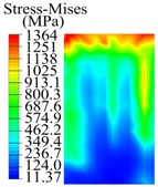 | 200 | 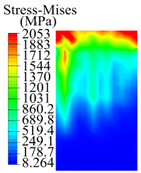 | 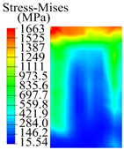 |
| 0.08 | 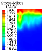 | 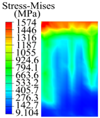 | 400 |  | 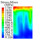 |
| 0.1 | 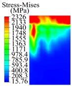 | 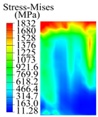 | 600 |  |  |
| 0.12 |  |  | 800 |  |  |
| BTA Drill | No. 1 Tool | No. 2 Tool | No. 3 Tool | No. 4 Tool |
|---|---|---|---|---|
| 1st guide pad |  | 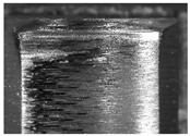 | 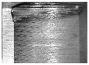 | 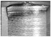 |
| 2nd guide pad | 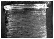 |  |  |  |
Publisher’s Note: MDPI stays neutral with regard to jurisdictional claims in published maps and institutional affiliations. |
© 2022 by the authors. Licensee MDPI, Basel, Switzerland. This article is an open access article distributed under the terms and conditions of the Creative Commons Attribution (CC BY) license (https://creativecommons.org/licenses/by/4.0/).
Share and Cite
Li, X.; Zheng, J.; Yu, B.; Du, Y.; Zhou, Y. Analytical Model of Hole Diameter and Self-Guiding Machining Mechanism of BTA Deep Hole Drilling. Materials 2022, 15, 5329. https://doi.org/10.3390/ma15155329
Li X, Zheng J, Yu B, Du Y, Zhou Y. Analytical Model of Hole Diameter and Self-Guiding Machining Mechanism of BTA Deep Hole Drilling. Materials. 2022; 15(15):5329. https://doi.org/10.3390/ma15155329
Chicago/Turabian StyleLi, Xubo, Jianming Zheng, Biao Yu, Yongqiang Du, and Yanan Zhou. 2022. "Analytical Model of Hole Diameter and Self-Guiding Machining Mechanism of BTA Deep Hole Drilling" Materials 15, no. 15: 5329. https://doi.org/10.3390/ma15155329
APA StyleLi, X., Zheng, J., Yu, B., Du, Y., & Zhou, Y. (2022). Analytical Model of Hole Diameter and Self-Guiding Machining Mechanism of BTA Deep Hole Drilling. Materials, 15(15), 5329. https://doi.org/10.3390/ma15155329