
CO Oxidation over Pd Catalyst Supported on Porous TiO2 Prepared by Plasma Electrolytic Oxidation (PEO) of a Ti Metallic Carrier

 ,
,  ,
,  ,
, 
Abstract
:
1. Introduction
2. Materials and Methods
2.1. Materials
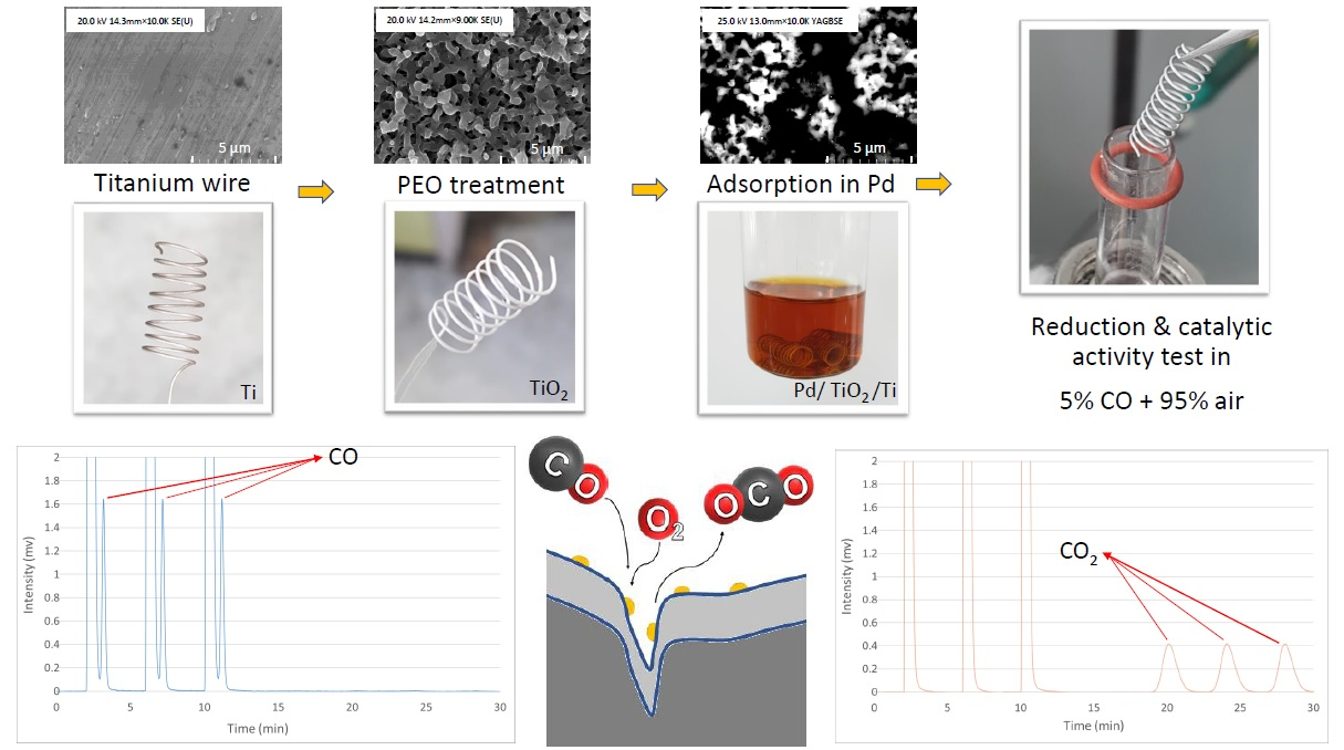
2.2. Preparation of Porous Layers of TiO2 on Ti Materials with PEO
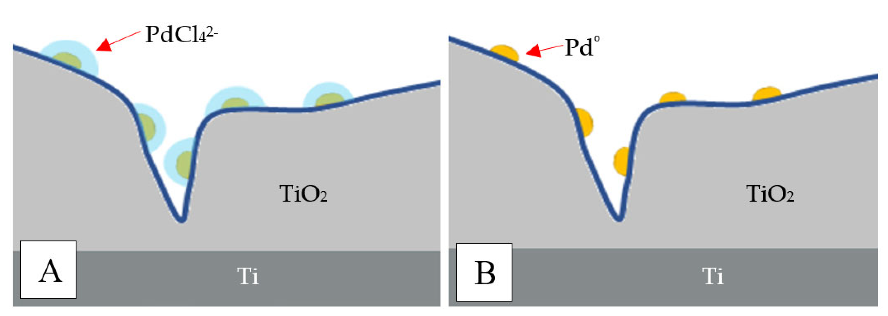
2.3. Preparation of Pd/TiO2/Ti Catalysts by the Adsorption Method
2.4. Catalytic Activity Test
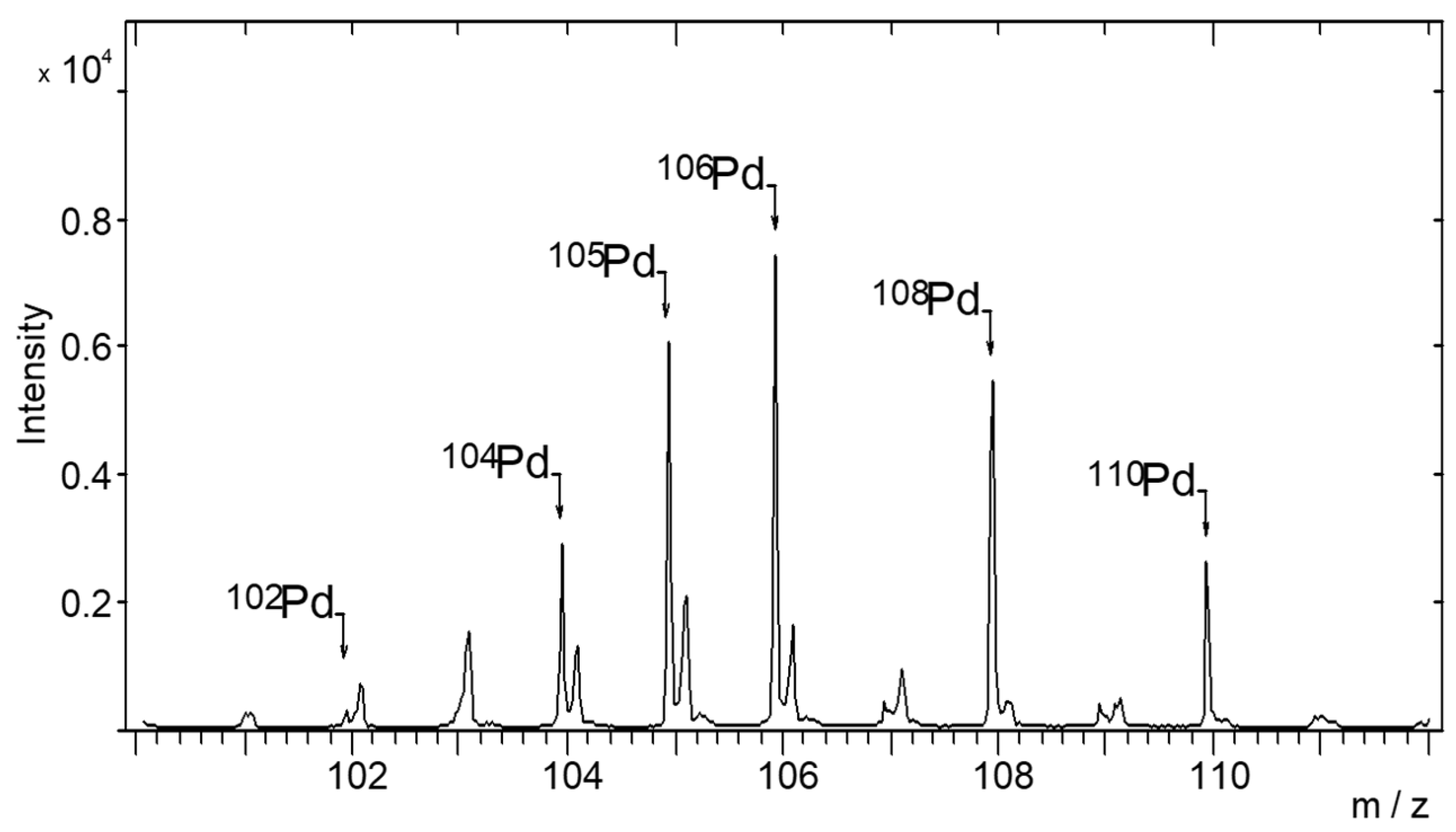
2.5. TOF-SIMS Test
2.6. Characterization of the Catalyst with ICP
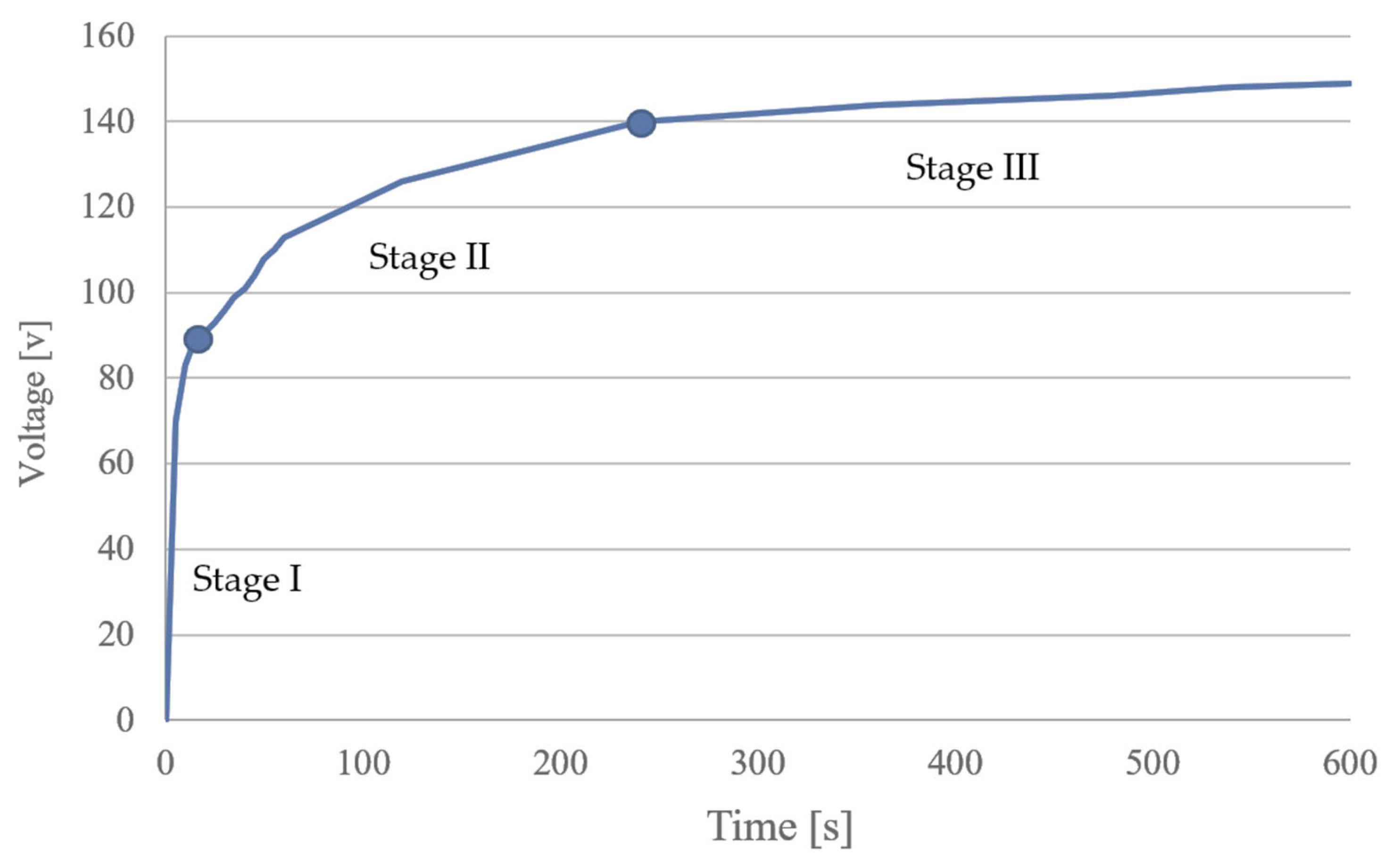
- Stage I (20 min): maximum pressure inside the reactor 130 bar; maximum temperature inside the reactor 230 °C; maximum microwave power 1500 W. Final temperature 230 °C.
- Stage II (10 min): maximum pressure inside the reactor 130 bar; maximum temperature inside the reactor 230 °C; maximum microwave power 1500 W. Final temperature 230 °C. The sample holder was placed in a Teflon container filled with water. This ensured the same conditions and access to microwave energy. Before sample decomposition, the whole reactor was pumped with nitrogen gas under a pressure of 40 bar. The gas phase acted as a cap for the vials, preventing boiling and cross-contamination of the solutions.
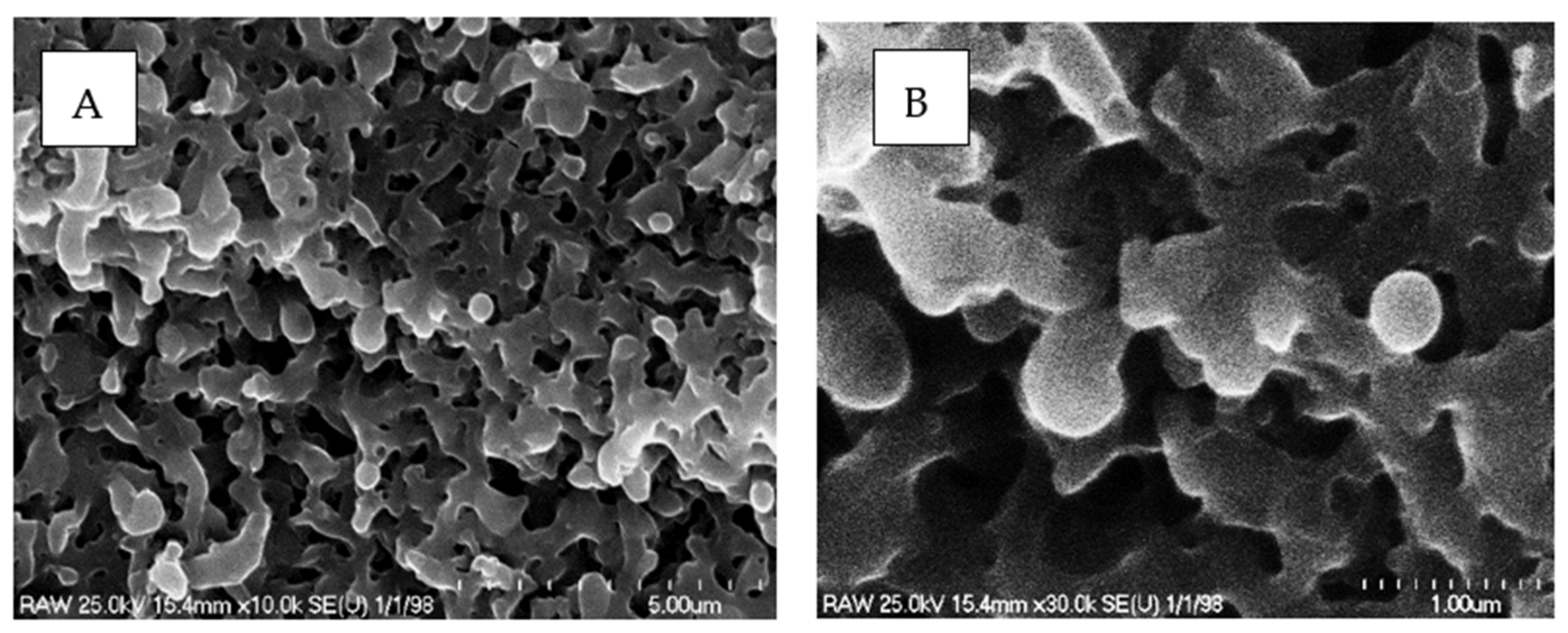
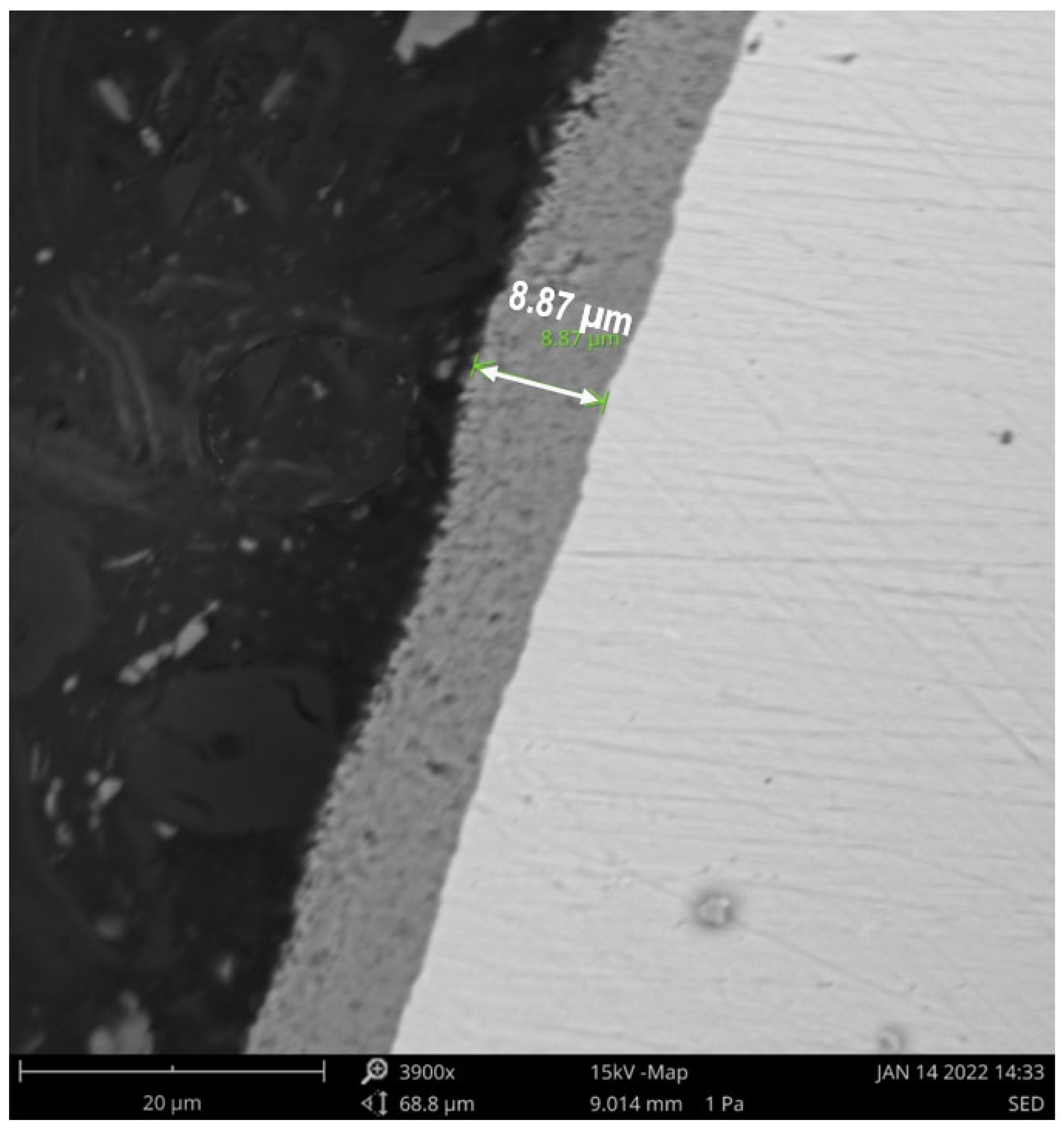
2.7. Characterization of the Catalyst with SEM
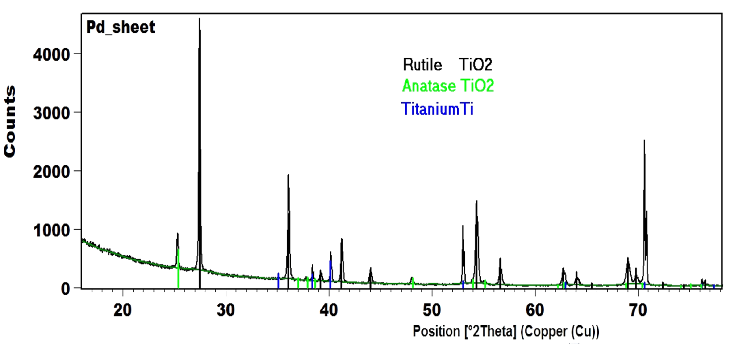
2.8. Characterization of the Catalyst with XRD
3. Results and Discussion
4. Conclusions
Author Contributions
Funding
Informed Consent Statement
Data Availability Statement
Conflicts of Interest
References
- Goshua, A.; Akdis, C.; Nadeau, K.C. World Health Organization Global Air Quality Guideline Recommendations: Executive Summary. Allergy 2022. [Google Scholar] [CrossRef] [PubMed]
- Yang, S.-H.; Chen, J.-M. Air Pollution Prevention and Pollution Source Identification of Chemical Industrial Parks. Process Saf. Environ. Prot. 2022, 159, 992–995. [Google Scholar] [CrossRef]
- Szyszkowicz, M. Urban Ambient Air Pollution and Substance Use Disorder. Air Qual. Atmos. Health 2022, 15, 1111–1120. [Google Scholar] [CrossRef]
- Rudnev, V.S.; Tyrina, L.M.; Ustinov, A.Y.; Vybornova, S.; Lukiyanchuk, I.V. Comparative Analysis of the Composition, Structure, and Catalytic Activity of the NiO-CuO-TiO2 on Titanium and NiO-CuO-Al2O3 on Aluminum Composites. Kinet. Catal. 2010, 51, 266–272. [Google Scholar] [CrossRef]
- Patcas, F.; Krysmann, W. Efficient Catalysts with Controlled Porous Structure Obtained by Anodic Oxidation under Spark-Discharge. Appl. Catal. A Gen. 2007, 316, 240–249. [Google Scholar] [CrossRef]
- Feng, C.; Liu, X.; Zhu, T.; Tian, M. Catalytic Oxidation of CO on Noble Metal-Based Catalysts. Environ. Sci. Pollut. Res. 2021, 28, 24847–24871. [Google Scholar] [CrossRef] [PubMed]
- Soliman, N.K. Factors Affecting CO Oxidation Reaction over Nanosized Materials: A Review. J. Mater. Res. Technol. 2019, 8, 2395–2407. [Google Scholar] [CrossRef]
- Mehrabadi, B.A.T.; Eskandari, S.; Khan, U.; White, R.D.; Regalbuto, J.R. Chapter One—A Review of Preparation Methods for Supported Metal Catalysts. In Advances in Catalysis; Song, C., Ed.; Academic Press: Cambridge, MA, USA, 2017; Volume 61, pp. 1–35. [Google Scholar]
- Chernykh, I.V.; Lukiyanchuk, I.V.; Rudnev, V.S.; Nedozorov, P.M.; Tyrina, L.M.; Ustinov, A.Y. Silicate Coatings on Titanium, Modified with Transition Metal Oxides and Their Activity in CO Oxidation. Russ. J. Appl. Chem. 2013, 86, 319–325. [Google Scholar] [CrossRef]
- Soled, S. Case Studies of Nobel-Metal Catalysts. In Synthesis of Solid Catalysts; John Wiley & Sons, Ltd.: Hoboken, NJ, USA, 2009; pp. 353–367. ISBN 978-3-527-62685-4. [Google Scholar]
- Rudnev, V.S.; Vasilyeva, M.S.; Kondrikov, N.B.; Tyrina, L.M. Plasma-Electrolytic Formation, Composition and Catalytic Activity of Manganese Oxide Containing Structures on Titanium. Appl. Surf. Sci. 2005, 252, 1211–1220. [Google Scholar] [CrossRef]
- Lugovskoy, A.; Zinigrad, M. Plasma Electrolytic Oxidation of Valve Metals; IntechOpen: Vienna, Austria, 2013; ISBN 978-953-51-1140-5. [Google Scholar]
- Sikdar, S.; Menezes, P.V.; Maccione, R.; Jacob, T.; Menezes, P.L. Plasma Electrolytic Oxidation (PEO) Process—Processing, Properties, and Applications. Nanomaterials 2021, 11, 1375. [Google Scholar] [CrossRef]
- Lukiyanchuk, I.V.; Rudnev, V.S.; Tyrina, L.M. Plasma Electrolytic Oxide Layers as Promising Systems for Catalysis. Surf. Coat. Technol. 2016, 307, 1183–1193. [Google Scholar] [CrossRef]
- Kaseem, M.; Fatimah, S.; Nashrah, N.; Ko, Y.G. Recent Progress in Surface Modification of Metals Coated by Plasma Electrolytic Oxidation: Principle, Structure, and Performance. Prog. Mater. Sci. 2021, 117, 100735. [Google Scholar] [CrossRef]
- Gupta, P.; Tenhundfeld, G.; Daigle, E.O.; Ryabkov, D. Electrolytic Plasma Technology: Science and Engineering—An Overview. Surf. Coat. Technol. 2007, 201, 8746–8760. [Google Scholar] [CrossRef]
- Rudnev, V.S. Micro- and Nano-Formations on the Surface of Plasma Electrolytic Oxide Coatings on Aluminum and Titanium. Surf. Coat. Technol. 2013, 235, 134–143. [Google Scholar] [CrossRef]
- Prando, D.; Brenna, A.; Diamanti, M.V.; Beretta, S.; Bolzoni, F.; Ormellese, M.; Pedeferri, M. Corrosion of Titanium: Part 2: Effects of Surface Treatments. J. Appl. Biomater. Funct. Mater. 2018, 16, 3–13. [Google Scholar] [CrossRef] [PubMed] [Green Version]
- Walsh, F.C.; Low, C.T.J.; Wood, R.J.K.; Stevens, K.T.; Archer, J.; Poeton, A.R.; Ryder, A. Plasma Electrolytic Oxidation (PEO) for Production of Anodised Coatings on Lightweight Metal (Al, Mg, Ti) Alloys. Trans. IMF 2009, 87, 122–135. [Google Scholar] [CrossRef]
- Mora-Sanchez, H.; del Olmo, R.; Rams, J.; Torres, B.; Mohedano, M.; Matykina, E.; Arrabal, R. Hard Anodizing and Plasma Electrolytic Oxidation of an Additively Manufactured Al-Si Alloy. Surf. Coat. Technol. 2021, 420, 127339. [Google Scholar] [CrossRef]
- Chen, H.; Tong, X.; Li, Y. Mesoporous Cu–Mn Hopcalite Catalyst and Its Performance in Low Temperature Ethylene Combustion in a Carbon Dioxide Stream. Appl. Catal. A Gen. 2009, 370, 59–65. [Google Scholar] [CrossRef]
- Pillai, U.R.; Deevi, S. Copper-Zinc Oxide and Ceria Promoted Copper-Zinc Oxide as Highly Active Catalysts for Low Temperature Oxidation of Carbon Monoxide. Appl. Catal. B Environ. 2006, 65, 110–117. [Google Scholar] [CrossRef]
- Tang, C.; Li, J.; Yao, X.; Sun, J.; Cao, Y.; Zhang, L.; Gao, F.; Deng, Y.; Dong, L. Mesoporous NiO–CeO2 Catalysts for CO Oxidation: Nickel Content Effect and Mechanism Aspect. Appl. Catal. A Gen. 2015, 494, 77–86. [Google Scholar] [CrossRef]
- Lukiyanchuk, I.V.; Chernykh, I.V.; Rudnev, V.S.; Ustinov, A.Y.; Tyrina, L.M.; Nedozorov, P.M.; Dmitrieva, E.E. Catalytically Active Cobalt-Copper-Oxide Layers on Aluminum and Titanium. Prot. Met. Phys. Chem. Surf. 2014, 50, 209–217. [Google Scholar] [CrossRef]
- Lu, J.-Q.; Sun, C.-X.; Li, N.; Jia, A.-P.; Luo, M.-F. Kinetic Study of CO Oxidation over CuO/MO2 (M = Si, Ti and Ce) Catalysts. Appl. Surf. Sci. 2013, 287, 124–134. [Google Scholar] [CrossRef]
- Luo, M.-F.; Fang, P.; He, M.; Xie, Y.-L. In Situ XRD, Raman, and TPR Studies of CuO/Al2O3 Catalysts for CO Oxidation. J. Mol. Catal. A Chem. 2005, 239, 243–248. [Google Scholar] [CrossRef]
- Snapkauskienė, V.; Valincius, V.; Valatkevičius, P. Experimental Study of Catalytic CO Oxidation over CuO/Al2O3 Deposited on Metal Sheets. Catal. Today 2011, 176, 77–80. [Google Scholar] [CrossRef]
- Lin, J.; Wang, X.; Zhang, T. Recent Progress in CO Oxidation over Pt-Group-Metal Catalysts at Low Temperatures. Chin. J. Catal. 2016, 37, 1805–1813. [Google Scholar] [CrossRef]
- Wei, S.; Fu, X.-P.; Wang, W.-W.; Jin, Z.; Song, Q.-S.; Jia, C.-J. Au/TiO2 Catalysts for CO Oxidation: Effect of Gold State to Reactivity. J. Phys. Chem. C 2018, 122, 4928–4936. [Google Scholar] [CrossRef]
- Tyrina, L.M.; Rudnev, V.S.; Yarovaya, T.P.; Ustinov, A.Y.; Lukiyanchuk, I.V.; Permyakov, V.V. Deposition, Composition, and Activity in CO Oxidation of Anodic Layers with Platinum on Aluminum and Titanium. Russ. J. Appl. Chem. 2010, 83, 680–686. [Google Scholar] [CrossRef]
- Royko, M.M.; Howell, S.; Faegh, E.; Mustain, W.; Lauterbach, J. Influence of Preparation Conditions on Platinum and Palladium Catalysts Supported on Anodically Oxidized Stainless Steel Wire Meshes for CO Oxidation. Emiss. Control. Sci. Technol. 2021, 7, 210–221. [Google Scholar] [CrossRef]
- Li, X.; Sun, X.; Xu, X.; Liu, W.; Peng, H.; Fang, X.; Wang, H.; Wang, X. CO Oxidation on PdO Catalysts with Perfect and Defective Rutile-TiO2 as Supports: Elucidating the Role of Oxygen Vacancy in Support by DFT Calculations. Appl. Surf. Sci. 2017, 401, 49–56. [Google Scholar] [CrossRef]
- Slavinskaya, E.M.; Kardash, T.Y.; Stonkus, O.A.; Gulyaev, R.V.; Lapin, I.N.; Svetlichnyi, V.A.; Boronin, A.I. Metal–Support Interaction in Pd/CeO2 Model Catalysts for CO Oxidation: From Pulsed Laser-Ablated Nanoparticles to Highly Active State of the Catalyst. Catal. Sci. Technol. 2016, 6, 6650–6666. [Google Scholar] [CrossRef]
- Vedyagin, A.A.; Volodin, A.M.; Kenzhin, R.M.; Chesnokov, V.V.; Mishakov, I.V. CO Oxidation over Pd/ZrO₂ Catalysts: Role of Support’s Donor Sites. Molecules 2016, 21, 1289. [Google Scholar] [CrossRef]
- Lukiyanchuk, I.V.; Papynov, E.K.; Rudnev, V.S.; Avramenko, V.A.; Chernykh, I.V.; Tyrina, L.M.; Ustinov, A.Y.; Kuryavyi, V.G.; Marinin, D.V. Oxide Layers with Pd-Containing Nanoparticles on Titanium. Appl. Catal. A Gen. 2014, 485, 222–229. [Google Scholar] [CrossRef]
- Shah, V.; Bhaliya, J.; Patel, G.M.; Joshi, P. Recent Advancement in Pd-Decorated Nanostructures for Its Catalytic and Chemiresistive Gas Sensing Applications: A Review. Top Catal. 2022, 1–41. [Google Scholar] [CrossRef]
- Burange, A.S.; Reddy, K.P.; Gopinath, C.S.; Shukla, R.; Tyagi, A.K. Role of Palladium Crystallite Size on CO Oxidation over CeZrO4-δ Supported Pd Catalysts. Mol. Catal. 2018, 455, 1–5. [Google Scholar] [CrossRef]
- Meier, M.; Hulva, J.; Jakub, Z.; Kraushofer, F.; Bobić, M.; Bliem, R.; Setvin, M.; Schmid, M.; Diebold, U.; Franchini, C.; et al. CO Oxidation by Pt2/Fe3O4: Metastable Dimer and Support Configurations Facilitate Lattice Oxygen Extraction. Sci. Adv. 2022, 8, eabn4580. [Google Scholar] [CrossRef]
- Rangel, R.; González-A, E.; Solís-García, A.; Zepeda, T.A.; Galván, D.H.; Gómez-Cortés, A.; Díaz, G. Pt and Ir Supported on Mixed Ce0.97Ru0.03O2 Oxide as Low-Temperature CO Oxidation Catalysts. Catal. Today 2022, 392–393, 3–12. [Google Scholar] [CrossRef]
- Kukovecz, Á.; Kordás, K.; Kiss, J.; Kónya, Z. Atomic Scale Characterization and Surface Chemistry of Metal Modified Titanate Nanotubes and Nanowires. Surf. Sci. Rep. 2016, 71, 473–546. [Google Scholar] [CrossRef] [Green Version]
- Bavykin, D.V.; Walsh, F.C. Titanate and Titania Nanotubes Synthesis, Properties and Applications Introduction and Scope. Assessment, U.E.N.C. for E. Available online: https://hero.epa.gov/hero/index.cfm/reference/details/reference_id/6864474 (accessed on 3 June 2022).
- Kiss, J.; Sápi, A.; Tóth, M.; Kukovecz, Á.; Kónya, Z. Rh-Induced Support Transformation and Rh Incorporation in Titanate Structures and Their Influence on Catalytic Activity. Catalysts 2020, 10, 212. [Google Scholar] [CrossRef] [Green Version]
- Kapteijn, F.; Moulijn, J.A. Structured Catalysts and Reactors—Perspectives for Demanding Applications. Catal. Today 2022, 383, 5–14. [Google Scholar] [CrossRef]
- Lukiyanchuk, I.V.; Rudnev, V.S.; Tyrina, L.M.; Chernykh, I.V. Plasma Electrolytic Oxide Coatings on Valve Metals and Their Activity in CO Oxidation. Appl. Surf. Sci. 2014, 315, 481–489. [Google Scholar] [CrossRef]
- Shi, Y.; Wang, Y.; Cheng, C.; Guo, X.; Teng, B.; Yu, Z.-P.; Li, J.; Li, W. Properties and Structure of PEO Treated Aluminum Alloy. J. Wuhan Univ. Technol. Mater. Sci. Ed. 2021, 36, 424–432. [Google Scholar] [CrossRef]
- Meyer, S.; Gorges, R.; Kreisel, G. Preparation and Characterisation of Titanium Dioxide Films for Catalytic Applications Generated by Anodic Spark Deposition. Thin Solid Films 2004, 450, 276–281. [Google Scholar] [CrossRef]
- Stojadinović, S.; Tadić, N.; Radić, N.; Grbić, B.; Vasilić, R. MgO/ZnO Coatings Formed on Magnesium Alloy AZ31 by Plasma Electrolytic Oxidation: Structural, Photoluminescence and Photocatalytic Investigation. Surf. Coat. Technol. 2017, 310, 98–105. [Google Scholar] [CrossRef]
- Si, R.; Liu, J.; Yang, K.; Chen, X.; Dai, W.; Fu, X. Temperature-Programed Surface Reaction Study of CO Oxidation over Au/TiO2 at Low Temperature: An Insight into Nature of the Reaction Process. J. Catal. 2014, 311, 71–79. [Google Scholar] [CrossRef]
- Lukiyanchuk, I.V.; Rudnev, V.S.; Tyrina, L.M.; Nedozorov, P.M.; Berestok, O.G. Formation, Structure, Composition, and Catalytic Properties of Ni-, Cu-, Mn-, Fe-, and Co-Containing Films on Aluminum. Russ. J. Appl. Chem. 2009, 82, 1000–1007. [Google Scholar] [CrossRef]
- Rudnev, V.S.; Lukiyanchuk, I.V.; Vasilyeva, M.S.; Medkov, M.A.; Adigamova, M.V.; Sergienko, V.I. Aluminum- and Titanium-Supported Plasma Electrolytic Multicomponent Coatings with Magnetic, Catalytic, Biocide or Biocompatible Properties. Surf. Coat. Technol. 2016, 307, 1219–1235. [Google Scholar] [CrossRef]
- Ahounbar, E.; Mousavi Khoei, S.M.; Urgen, M.; Shokouhimehr, M. Characteristics of the Hierarchical Porous TiO2 Layer Synthesized on Ti via Plasma Electrolytic Oxidation: Role of the Applied Voltage. Ceram. Int. 2021, 47, 8279–8289. [Google Scholar] [CrossRef]
- Suh, D.J.; Park, T.J.; Ihm, S.K. Characteristics of Carbon-Supported Palladium Catalysts for Liquid-Phase Hydrogenation of Nitroaromatics. Ind. Eng. Chem. Res. 1992, 31, 1849–1856. [Google Scholar] [CrossRef]
- Amadou, J.; Chizari, K.; Houllé, M.; Janowska, I.; Ersen, O.; Bégin, D.; Pham-Huu, C. N-Doped Carbon Nanotubes for Liquid-Phase CC Bond Hydrogenation. Catal. Today 2008, 138, 62–68. [Google Scholar] [CrossRef]
- Brunelle, J.P. Preparation of Catalysts by Metallic Complex Adsorption on Mineral Oxides. Pure Appl. Chem. 1978, 50, 1211–1229. [Google Scholar] [CrossRef]
- Parks, G.A. The Isoelectric Points of Solid Oxides, Solid Hydroxides, and Aqueous Hydroxo Complex Systems. Chem. Rev. 1965, 65, 177–198. [Google Scholar] [CrossRef]
- Pinna, F. Supported Metal Catalysts Preparation. Catal. Today 1998, 41, 129–137. [Google Scholar] [CrossRef]
- Sheldon, R.A.; Santen, R.A.V. Catalytic Oxidation: Principles and Applications—A Course of The Netherlands Institute for Catalysis Research (Niok); World Scientific: Singapore, 1995; ISBN 978-981-4579-71-1. [Google Scholar]
- Scherson, D. Fundamentals of Energy Storage and Conversion: ECS Transactions; The Electrochemical Society: Philadelphia, PA, USA, 2008; Volume 13, ISBN 978-1-56677-675-2. [Google Scholar]
- Allian, A.D.; Takanabe, K.; Fujdala, K.L.; Hao, X.; Truex, T.J.; Cai, J.; Buda, C.; Neurock, M.; Iglesia, E. Chemisorption of CO and Mechanism of CO Oxidation on Supported Platinum Nanoclusters. J. Am. Chem. Soc. 2011, 133, 4498–4517. [Google Scholar] [CrossRef] [PubMed]
- Van Spronsen, M.A.; Frenken, J.W.M.; Groot, I.M.N. Surface Science under Reaction Conditions: CO Oxidation on Pt and Pd Model Catalysts. Chem. Soc. Rev. 2017, 46, 4347–4374. [Google Scholar] [CrossRef] [PubMed] [Green Version]
- Murata, K.; Eleeda, E.; Ohyama, J.; Yamamoto, Y.; Arai, S.; Satsuma, A. Identification of Active Sites in CO Oxidation over a Pd/Al2O3 Catalyst. Phys. Chem. Chem. Phys. 2019, 21, 18128–18137. [Google Scholar] [CrossRef]


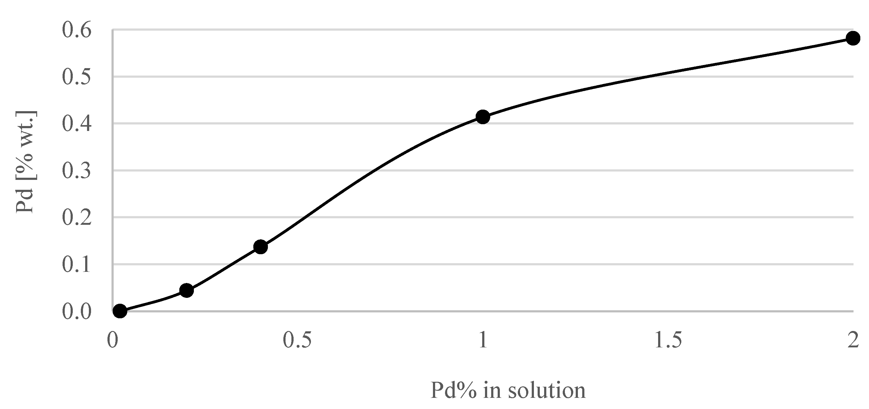
| Concentration of Pd in Solutions (%) | Amount of Pd in Catalyst (% wt.) |
|---|---|
| 0.02 | <0.001 |
| 0.2 | 0.044 |
| 0.4 | 0.137 |
| 1 | 0.414 |
| 2 | 0.581 |
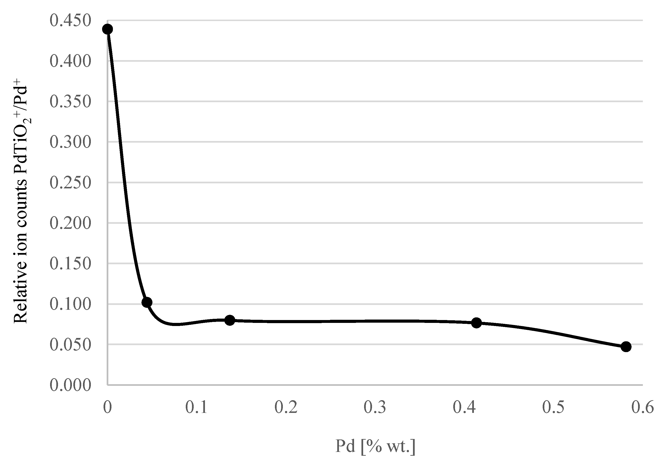
| % Pd in Solution | TOF-SIMS Secondary Ion Counts | Relative Values of Ion Counts | |
|---|---|---|---|
| Pd+ | PdTiO2+ | PdTiO2+/Pd+ | |
| 0.02 | 565 | 248 | 0.439 |
| 0.2 | 2621 | 267 | 0.102 |
| 0.4 | 8400 | 670 | 0.08 |
| 1 | 3917 | 300 | 0.077 |
| 2 | 12276 | 578 | 0.047 |
Publisher’s Note: MDPI stays neutral with regard to jurisdictional claims in published maps and institutional affiliations. |
© 2022 by the authors. Licensee MDPI, Basel, Switzerland. This article is an open access article distributed under the terms and conditions of the Creative Commons Attribution (CC BY) license (https://creativecommons.org/licenses/by/4.0/).
Share and Cite
Samadi, P.; Binczarski, M.J.; Pawlaczyk, A.; Rogowski, J.; Szynkowska-Jozwik, M.I.; Witonska, I.A. CO Oxidation over Pd Catalyst Supported on Porous TiO2 Prepared by Plasma Electrolytic Oxidation (PEO) of a Ti Metallic Carrier. Materials 2022, 15, 4301. https://doi.org/10.3390/ma15124301
Samadi P, Binczarski MJ, Pawlaczyk A, Rogowski J, Szynkowska-Jozwik MI, Witonska IA. CO Oxidation over Pd Catalyst Supported on Porous TiO2 Prepared by Plasma Electrolytic Oxidation (PEO) of a Ti Metallic Carrier. Materials. 2022; 15(12):4301. https://doi.org/10.3390/ma15124301
Chicago/Turabian StyleSamadi, Payam, Michal J. Binczarski, Aleksandra Pawlaczyk, Jacek Rogowski, Malgorzata I. Szynkowska-Jozwik, and Izabela A. Witonska. 2022. "CO Oxidation over Pd Catalyst Supported on Porous TiO2 Prepared by Plasma Electrolytic Oxidation (PEO) of a Ti Metallic Carrier" Materials 15, no. 12: 4301. https://doi.org/10.3390/ma15124301
APA StyleSamadi, P., Binczarski, M. J., Pawlaczyk, A., Rogowski, J., Szynkowska-Jozwik, M. I., & Witonska, I. A. (2022). CO Oxidation over Pd Catalyst Supported on Porous TiO2 Prepared by Plasma Electrolytic Oxidation (PEO) of a Ti Metallic Carrier. Materials, 15(12), 4301. https://doi.org/10.3390/ma15124301