
Investigation of the Reusability of a Polyurethane-Bound Noise-Absorbing Pavement in Terms of Reclaimed Asphalt Pavement


Abstract
:1. Introduction
- They use polyurethane binder (i.e., Elastopave®), of which 83% of the polyol component can be produced from renewable raw materials (e.g., ricinus oil) and thus, they distance themselves from the conventional binder bitumen, which is not a renewable raw material [10].
- They can reduce the heat island effect in cities, because of its density and low heat storage capacity [10].
2. Methodology and Materials
2.1. Methodology
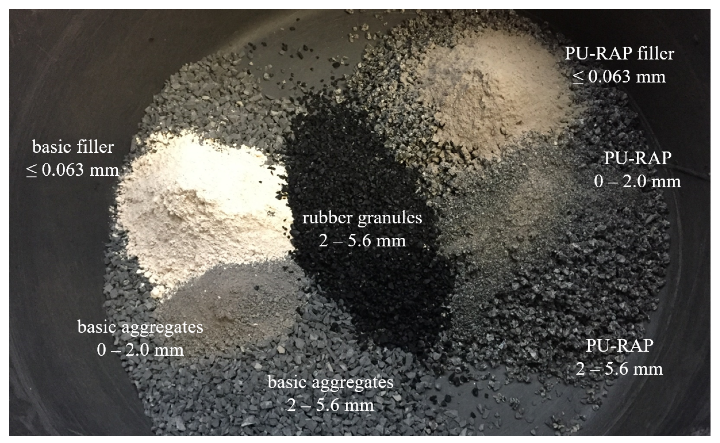
2.2. Material
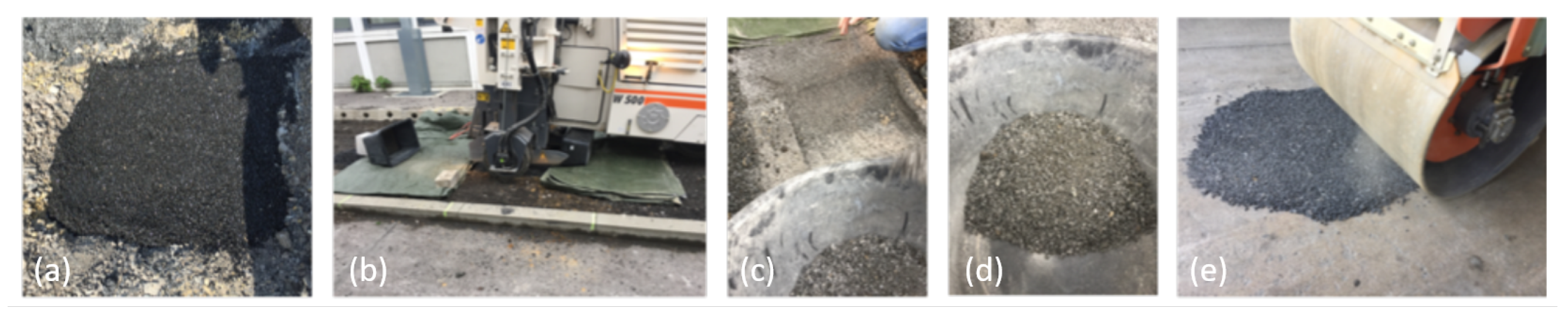
2.2.1. Preparation of the PU-RAP
2.2.2. Design of the Test Variants
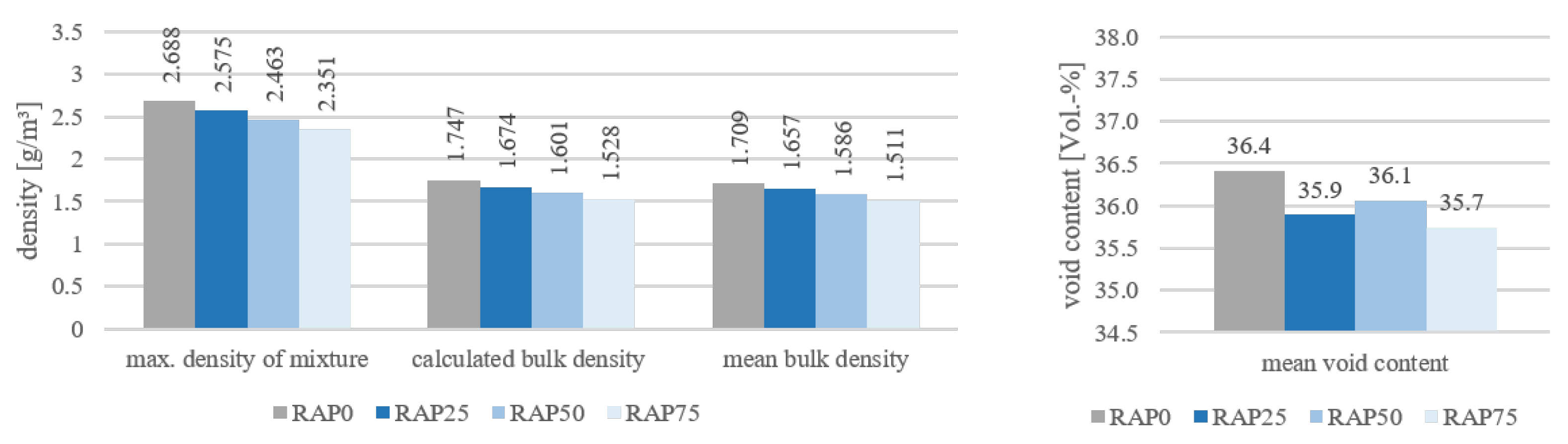
2.2.3. Densities and Void Contents of Tested Specimens
2.3. Selection of Suitable Test Methods
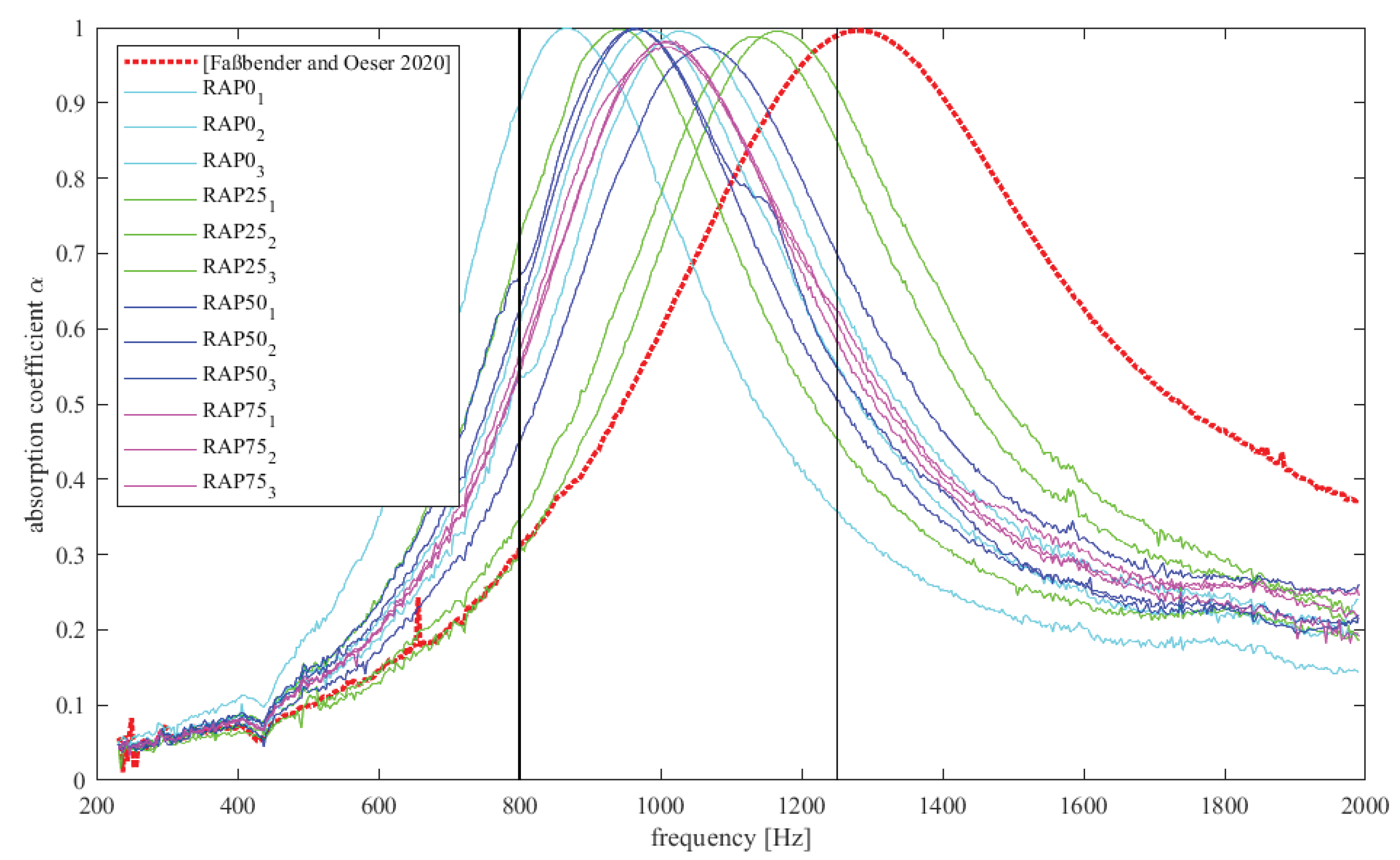
2.3.1. Absorption Behaviour
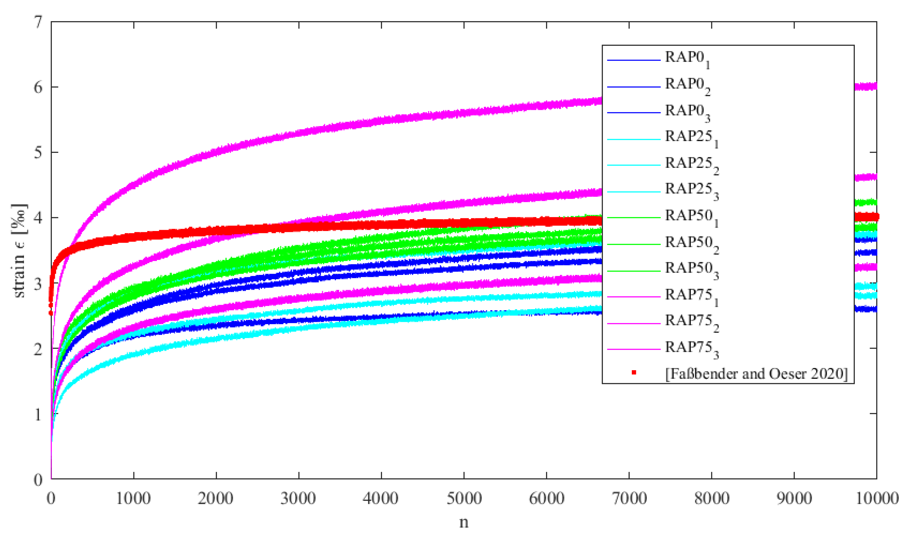
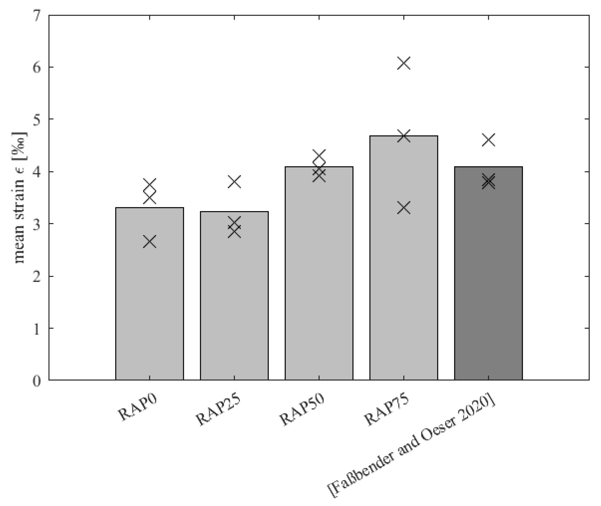
2.3.2. Deformation Resistance with Uniaxial Cyclic Compression Test (UCCT)
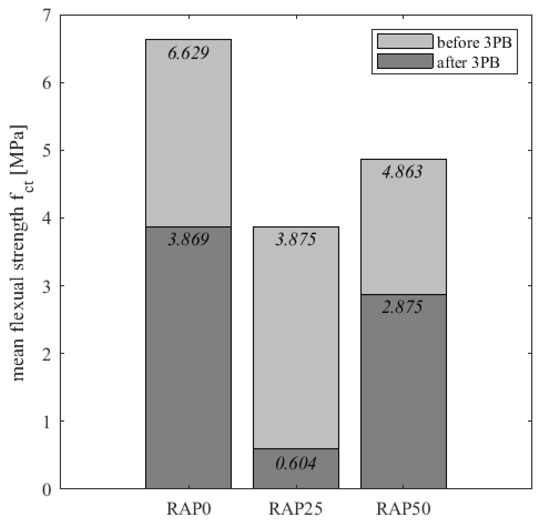
2.3.3. Fatigue Behaviour with Three Point Bending Test (3PB)
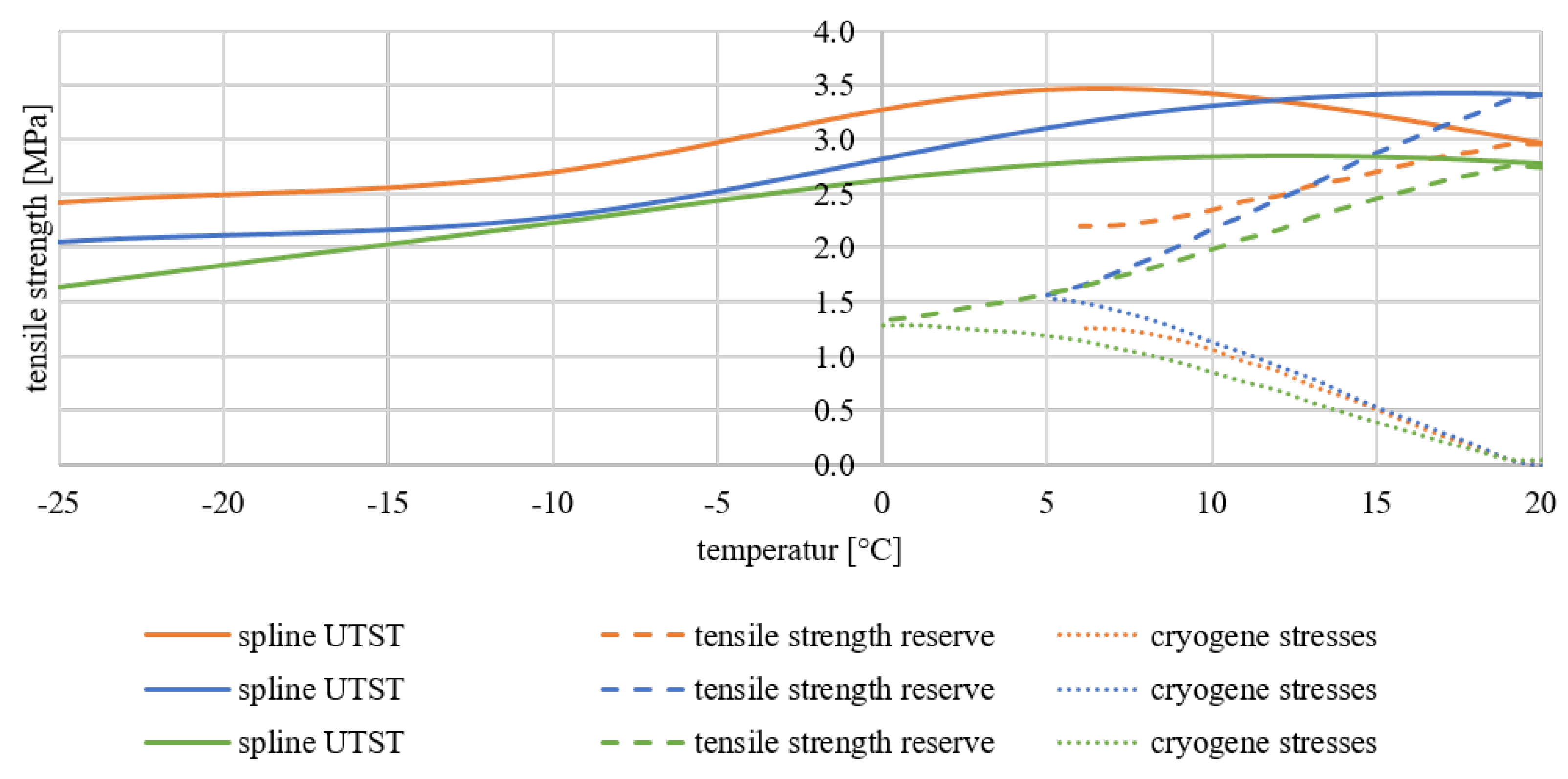
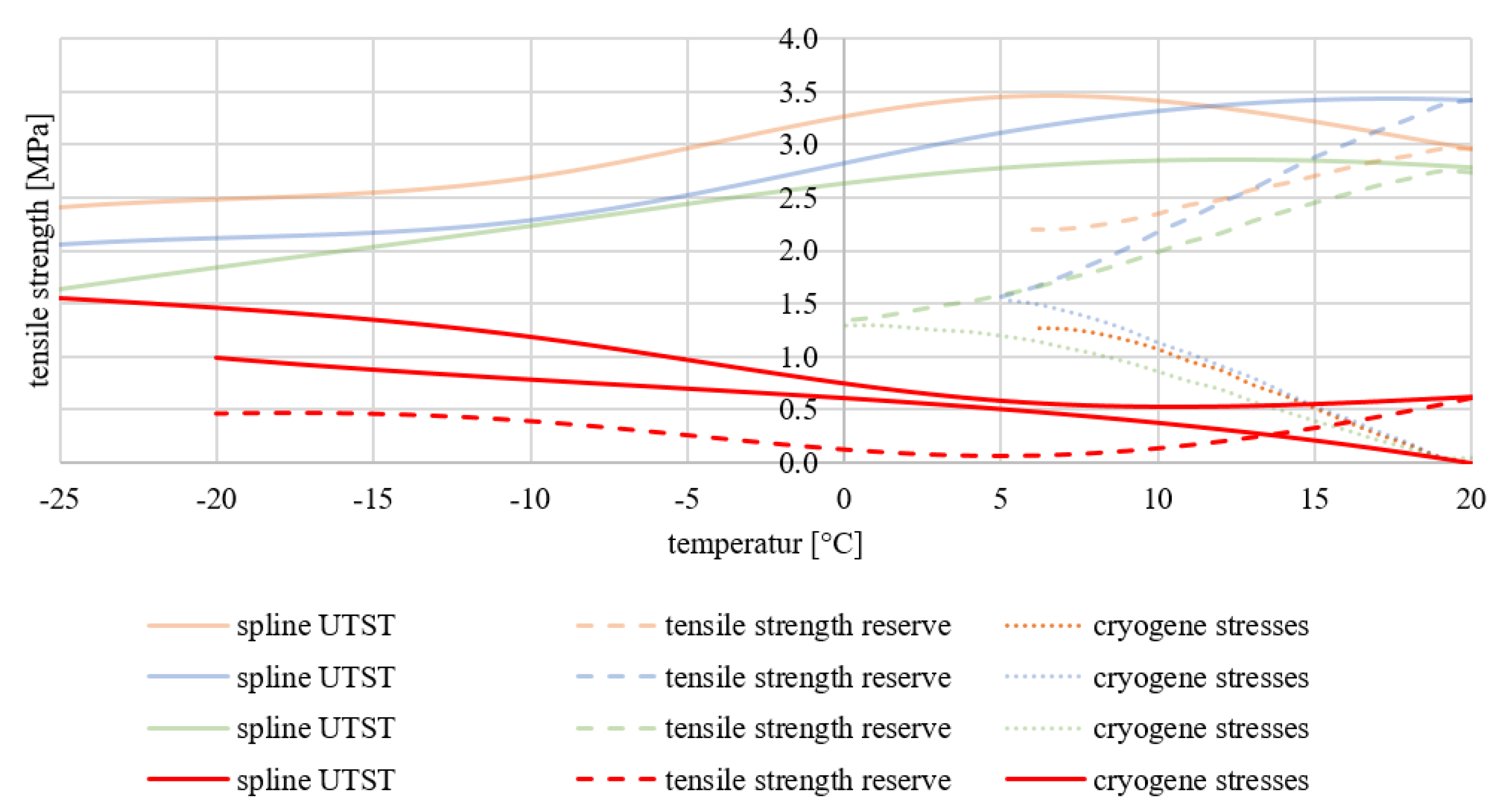
2.3.4. Low Temperature Behaviour
Uniaxial Tension Stress Test (UTST)
Thermal Stress Restrained Specimen Test (TSRST)
3. Experimental Results and Discussion
3.1. Densities and Void Contents
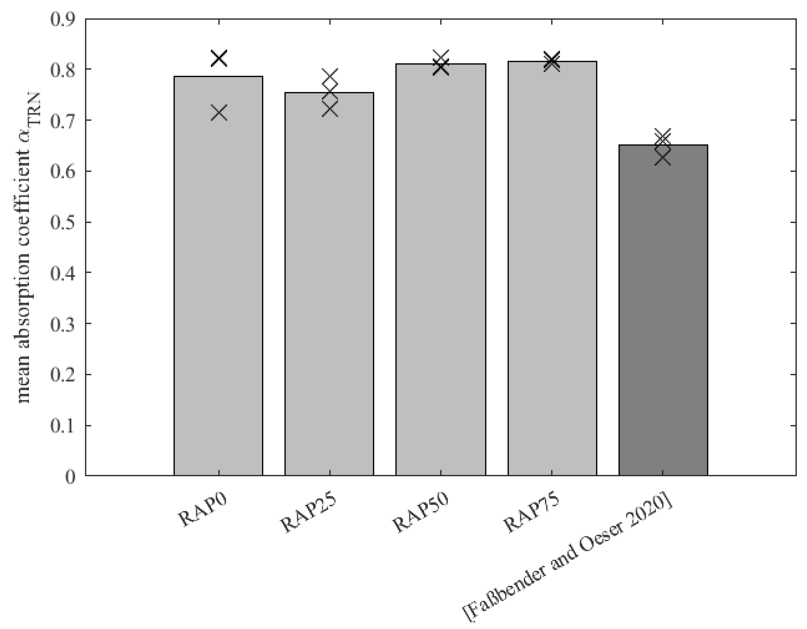
3.2. Absorption Potential
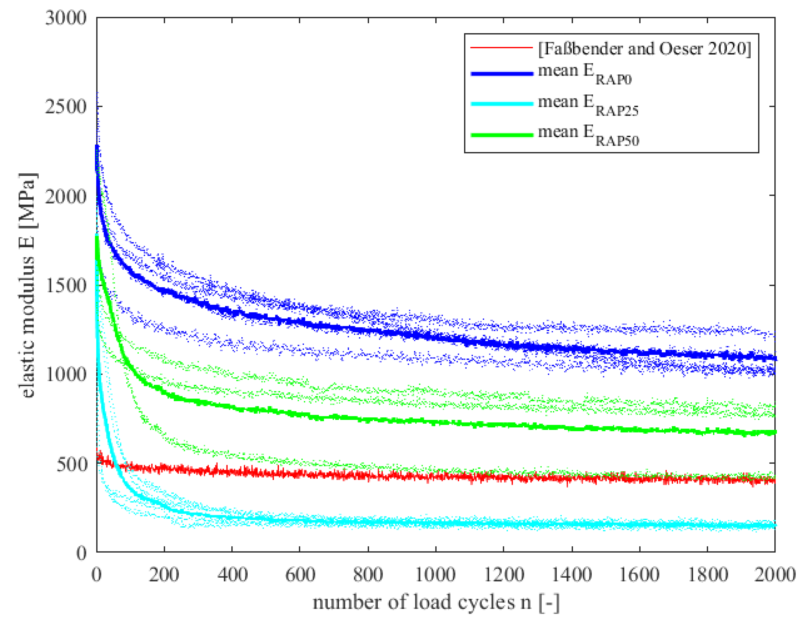
3.3. Uniaxial Cyclic Compression Test
3.4. Three Point Bending Test
3.5. Results of Low-Temperature Behaviour
4. Conclusions
- The addition of PU-RAP has a positive influence on the absorption capacity of the polyurethane-bound rubber-modified pavement, as the frequency range can be adjusted.
- The addition of PU-RAP has no significant effect on the deformation behaviour of polyurethane-bound rubber-modified pavement.
- The addition of PU-RAP does not affect the resistance to fatigue of the polyurethane-bound rubber-modified pavement.
- The addition of PU-RAP has no effect on the low-temperature behaviour of the polyurethane-bound rubber-modified pavement.
- The RAP was freshly made, unstressed and unaged when it was reconditioned. The study, in the first step, intended to show the feasibility of reusing the PU-RAP. In the next step, it makes sense to take the RAP material from already stressed pavements and to investigate the functionality.
- All tests should be prepared and tested again with the one-component binder from [3] to generate comparability. The influence of the PU-RAP can likely be worked out even better in this case.
- Additional specimens should be tested to support the conclusions made in this study.
Author Contributions
Funding
Institutional Review Board Statement
Informed Consent Statement
Data Availability Statement
Acknowledgments
Conflicts of Interest
Abbreviations
| 3PB | three point bending beam test |
| PU | polyurethane |
| PU-RAP | polyurethane based reclaimed asphalt pavement |
| RAP | Reclaimed asphalt pavement |
| TSRST | Thermal Stress Restrained Specimen Test |
| UTST | Tension Stress Test |
Appendix A

| Aggregate Size [mm] | Maximum Density [g/cm] | |
|---|---|---|
| lime sandstone filler | ≤0.063 | 2.730 |
| PU-RAP filler | ≤0.063 | 2.582 |
| basalt stone | 0.063–2.0 | 3.050 |
| PU-RAP | 0.063–2.0 | 2.588 |
| basalt stone | 2.0–5.6 | 3.050 |
| PU-RAP | 2.0–5.6 | 2.605 |
| rubber super-grob | 2.0–5.6 | 1.100 |
| polyurethane | - | 1.100 |
| Characteristics | Unit | Measured Value | Method |
|---|---|---|---|
| Hardness | Shore ID | 72 | DIN 53505 |
| Tensile strenth | N/mm² | 32 | DIN EN ISO 527 |
| Elongation | % | 40 | DIN EN ISO 527 |
| Tear strength | N/mm | 40 | DIN 53515 |
| Density | g/cm³ | 1.1 | DIN 53420 |
References
- European Commission. A New Circular Economy Action Plan-For a Cleaner and More Competitive Europe; European Commission: Brussels, Belgium, 2020. [Google Scholar]
- United Nations. Transforming Our World: The 2030 Agenda for Sustainable Development (A/RES/70/1); United Nations: New York, NY, USA, 2015. [Google Scholar]
- Faßbender, S.; Oeser, M. Investigation on an Absorbing Layer Suitable for a Noise-Reducing Two-Layer Pavement. Materials 2020, 13, 1235. [Google Scholar] [CrossRef] [Green Version]
- Goubert, L. Above the development and use of the poro-elastic road surface. Presented at the Road Research Meeting FeRRM, Brussels, Belgium, 18–20 October 2011. [Google Scholar]
- Goubert, L.; Sandberg, U. The PERSUADE project: Developing the concept of poroelastic road surface into a powerful tool for abating traffic noise. In Proceedings of the INTER-NOISE 2010—39th International Congress on Noise Control Engineering 2010, Lisbon, Portugal, 15–16 June 2010. [Google Scholar]
- Sandberg, U.; Ejsmont, J.A. Tyre/Road Noise Reference Handbook; Informex Ejsmont and Sandberg Handelbolag: Kisa, Sweden, 2002. [Google Scholar]
- Schacht, A. Entwicklung Künstlicher Straßendeckschichtsysteme auf Kunststoffbasis zur Geräuschreduzierung Mit Numerischen und Empirischen Verfahren. Aachener Mitteilungen Straßenwesen, Erd- und Tunnelbau. Ph.D. Thesis, RWTH Aachen University, Aachen, Germany, 2015. Volume 63. [Google Scholar]
- Kaiser, W. Kunststoffchemie für Ingenieure; Carl Hanser Verlag: Muenchen, Germany, 2007. [Google Scholar]
- BASF Polyurethanes GmbH. Build a Brighter Future with Sustainable Construction. Available online: https://plastics-rubber.basf.com/global/de/performance_polymers/industries/pp_construction/sustainability.html (accessed on 10 April 2022).
- Renken, L. Development of PU-Asphalt-From the Concept to the Practical Implementation. Ph.D. Thesis, RWTH Aachen University, Aachen, Germany, 2019. [Google Scholar]
- Oeser, M.; Schacht, A. Abschlussbericht Leise Innovative Deckschicht auf Kunststoffbasis (LIDAK). FE 88.0108/2011, 2014. [Google Scholar]
- Renken, L.; Oeser, M.; Wimmer, J.; Reese, S.; Pape, H.; Huckschlag, C. Schlussbericht INNO-BOND—Simulationsgestützte Entwicklung neuer Straßenbaustoffe und Innovativer Herstellungs- und Einbautechnologien. FE 07.0264/2012/ARB, 2016. [Google Scholar]
- Oeser, M.; Faßbender, S.; Reese, S.; Eggersmann, R.; Gries, T.; Koch, A. INNO-PAVE: Schlussbericht (Project Report) zum Teilvorhaben: “Grundlagen der konstruktiven Gestaltung, Struktur Sowie Neuer Polymerer Werkstoffe für Straßendeckschichtsysteme” im Verbundprojekt: “Grundlegende Erforschung polymerer Werkstoffe sowie innovativer Herstellungs- und Einbautechnologien für Straßendeckschichtsysteme”, 13XP5001F. Available online: https://www.tib.eu/de/suchen/id/TIBKAT:1688463194/INNO-PAVE-Schlussbericht-zum-Teilvorhaben-Grundlagen?cHash=4993e942e93308ba3fb4fe985f3404f0 (accessed on 2 February 2022).
- Renken, L.; Kreischer, S.; Oeser, M. Entwicklung von Deckschichtmaterialien für versickerungsfähige Verkehrsflächenbefestigungen auf Basis alternativer Bindemittel-Teil II: Ansprache der Performance. Straße Autobahn 2003, 9, 776–784. [Google Scholar]
- Lu, G. Permeable Pavements-Hydraulic and Mechanical Investigations. Ph.D. Thesis, RWTH Aachen University, Aachen, Germany, 2019. [Google Scholar]
- Technische Lieferbedingungen für Asphaltgranulat (TL AG-StB). Road and Transportation Research Association (FGSV) No. 749; FGSV: Cologne, Germany, 2009. [Google Scholar]
- Merkblatt für die Wiederverwendung von Asphalt (M WA). Road and Transportation Research Association (FGSV) No. 754; FGSV: Cologne, Germany, 2013. [Google Scholar]
- Technische Prüfvorschriften für Asphalt (TP Asphalt-StB). Teil 5 Rohdichte von Asphalt. In Road and Transportation Research Association (FGSV) No. 756/6; FGSV: Cologne, Germany, 2021. [Google Scholar]
- Technische Prüfvorschriften für Asphalt (TP Asphalt-StB). Teil 6 Raumdichte von Asphalt-Probekörpern. Road and Transportation Research Association (FGSV) No. 756/6; FGSV: Cologne, Germany, 2012. [Google Scholar]
- DIN EN ISO 10534-2:2001; Acoustics-Determination of Sound Absorption Coefficient and Impedance in Impedance Tubes-Part 2: Transfer-Function Method. German Version EN ISO 10534-2:2001. European Standard: Berlin, Germany, 2001.
- Möser, M. Schallabsorption. In Technische Akustik; Springer: Berlin/Heidelberg, Germany, 2012; pp. 177–225. [Google Scholar]
- Technische Prüfvorschriften für Asphalt (TP Asphalt-StB). Teil 25 B 1 Einaxialer Druck-Schwellversuch-Bestimmung des Verformungsverhaltens von Walzasphalt bei Wärme. In Road and Transportation Research Association (FGSV) no. 756/25 B1; FGSV: Cologne, Germany, 2012. [Google Scholar]
- Zhang, Z.; Kohlmeier, J.; Schulze, C.; Oeser, M. Concept and Development of an Accelerated Repeated Rolling Wheel Load Simulator (ARROWS) for Fatigue Performance Characterization of Asphalt Mixture. Materials 2021, 14, 7838. [Google Scholar] [CrossRef] [PubMed]
- DIN EN 12697-24:2018; Bituminious Mixtures-Test Methods-Part 24: Resistance to Fatigue. German Version EN 12697-24:2018. European Standard: Berlin, Germany, 2018.
- Technische Prüfvorschriften für Asphalt (TP Asphalt-StB). Teil 46 A Kälteeigenschaften-Einaxialer Zugversuch und Abkühlversuch. In Road and Transportation Research Association (FGSV) No. 756/46 A; FGSV: Cologne, Germany, 2013. [Google Scholar]
- Beckenbauer, T. Physik der Reifen-Fahrbahn-Geräusche-Geräuschentstehung, Wirkmechanismen und akustische Wirkung unter dem Einfluss von Bautechnik und Straßenbetrieb. In Geräuschmindernde Straßenbeläge Der-Praxis-Lärmaktionsplanung; Müller-BBM: Gelsenkirchen, Germany, 2008; Volume 4. [Google Scholar]
- Praticò, F.G.; Vizzari, D.; Fedele, R. Estimating the resistivity and tortuosity of a road pavement using an inverse problem approach. In Proceedings of the 24th International Congress on Sound and Vibration, London, UK, 23–27 July 2017. [Google Scholar]
- DIN EN 12390-5:2019-10; Testing Hardened Concrete—Part 5: Flexural Strength of Test Specimens. German Version EN 12390-5:2009. European Standard: Berlin, Germany, 2009.


| Mixture Components | Amount | Unit |
|---|---|---|
| aggregates | 80.5 | vol.% |
| rubber granules | 6.5 | vol.% |
| two-component polyurethane | 13 | vol.% |
| Variant | RAP0 | RAP25 | RAP50 | RAP75 | |
|---|---|---|---|---|---|
| PU-RAP | [vol.%] | 0 | 25 | 50 | 75 |
| Variant | Specimen No. | [MPa] | [-] | [MPa] |
|---|---|---|---|---|
| [3] | - | 537 | not reached | 386 |
| RAP0 | 5 | 1671 | not reached | 1013 |
| 7 | 1998 | not reached | 1212 | |
| 8 | 1903 | not reached | 1101 | |
| 9 | 2232 | 1262 | 1042 | |
| RAP25 | 7 | 467 | 202 | 152 |
| 8 | 1431 | 62 | 173 | |
| 9 | 1393 | 50 | 137 | |
| 10 | 558 | 53 | 133 | |
| RAP50 | 5 | 2091 | 82 | 430 |
| 7 | 1460 | not reached | 831 | |
| 10 | 1266 | not reached | 779 |
Publisher’s Note: MDPI stays neutral with regard to jurisdictional claims in published maps and institutional affiliations. |
© 2022 by the authors. Licensee MDPI, Basel, Switzerland. This article is an open access article distributed under the terms and conditions of the Creative Commons Attribution (CC BY) license (https://creativecommons.org/licenses/by/4.0/).
Share and Cite
Faßbender, S.; Oeser, M. Investigation of the Reusability of a Polyurethane-Bound Noise-Absorbing Pavement in Terms of Reclaimed Asphalt Pavement. Materials 2022, 15, 3040. https://doi.org/10.3390/ma15093040
Faßbender S, Oeser M. Investigation of the Reusability of a Polyurethane-Bound Noise-Absorbing Pavement in Terms of Reclaimed Asphalt Pavement. Materials. 2022; 15(9):3040. https://doi.org/10.3390/ma15093040
Chicago/Turabian StyleFaßbender, Sabine, and Markus Oeser. 2022. "Investigation of the Reusability of a Polyurethane-Bound Noise-Absorbing Pavement in Terms of Reclaimed Asphalt Pavement" Materials 15, no. 9: 3040. https://doi.org/10.3390/ma15093040
APA StyleFaßbender, S., & Oeser, M. (2022). Investigation of the Reusability of a Polyurethane-Bound Noise-Absorbing Pavement in Terms of Reclaimed Asphalt Pavement. Materials, 15(9), 3040. https://doi.org/10.3390/ma15093040