
Corrosion of Alumina-Spinel Refractory by Secondary Metallurgical Slag Using Coating Corrosion Test

 ,
,  and
and 
Abstract
:
1. Introduction
2. Materials and Methods
2.1. Preparation of Slag
2.2. Alumina-Spinel Brick
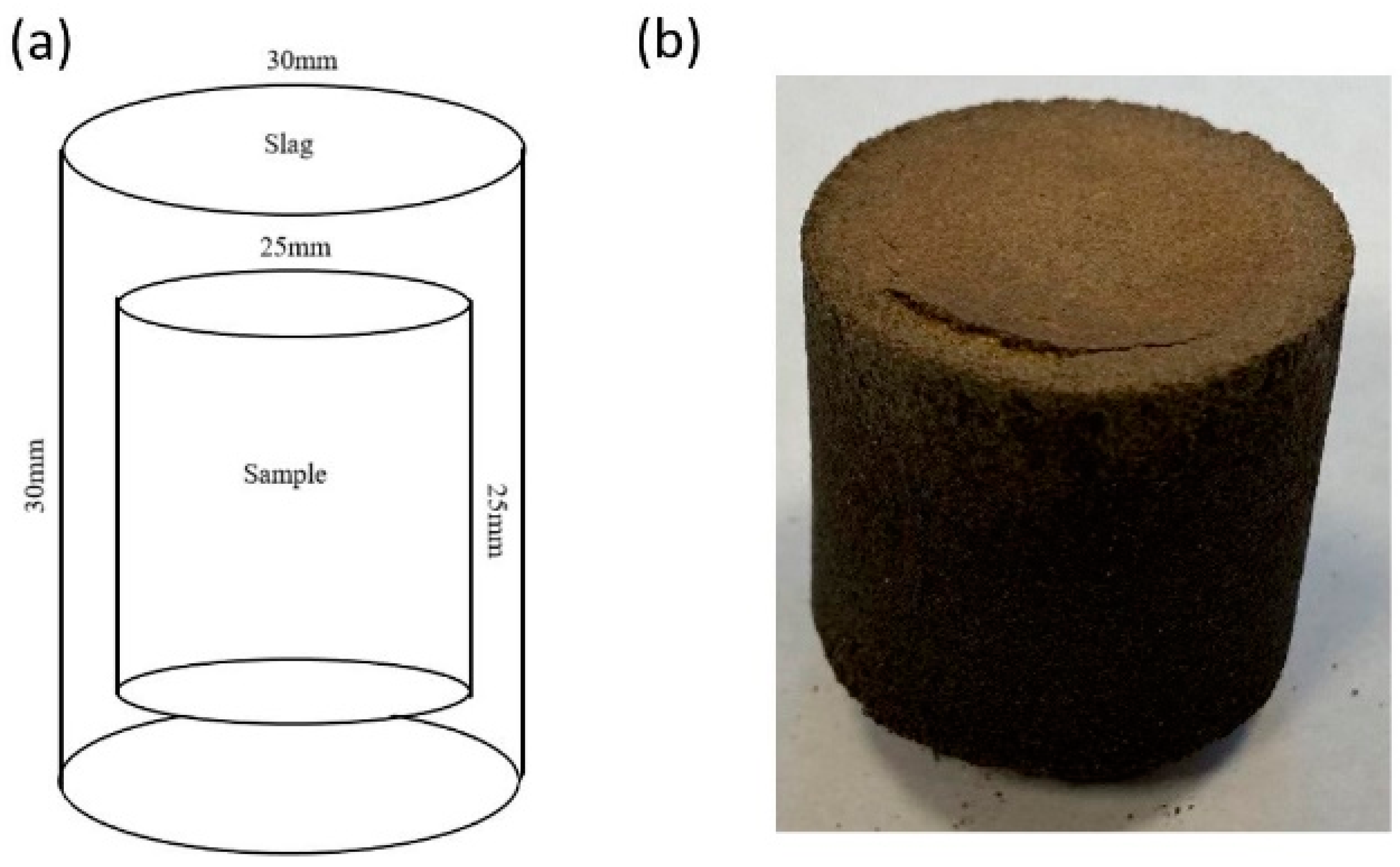
2.3. Corrosion Test
2.4. Analysis of Material before and after Corrosion
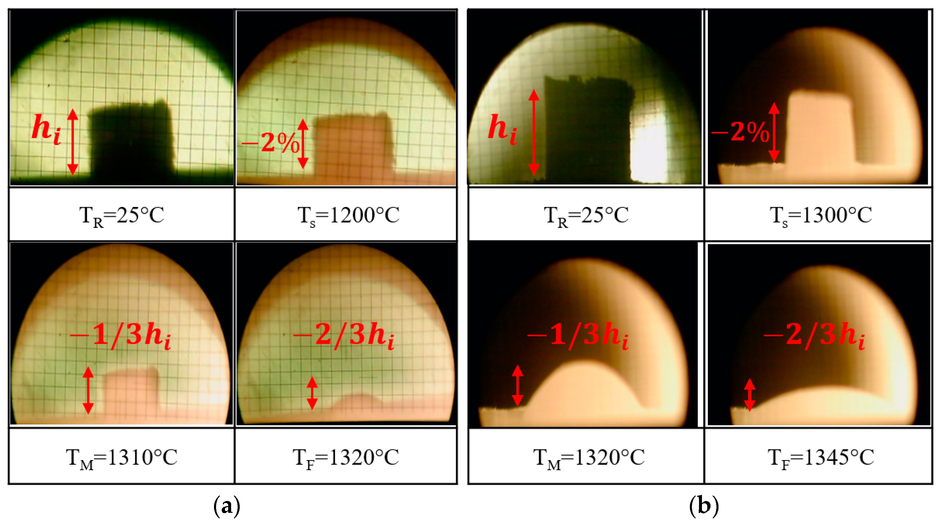
- —the initial height of the sample;
- —the height of the sample at a specific temperature.
3. Results
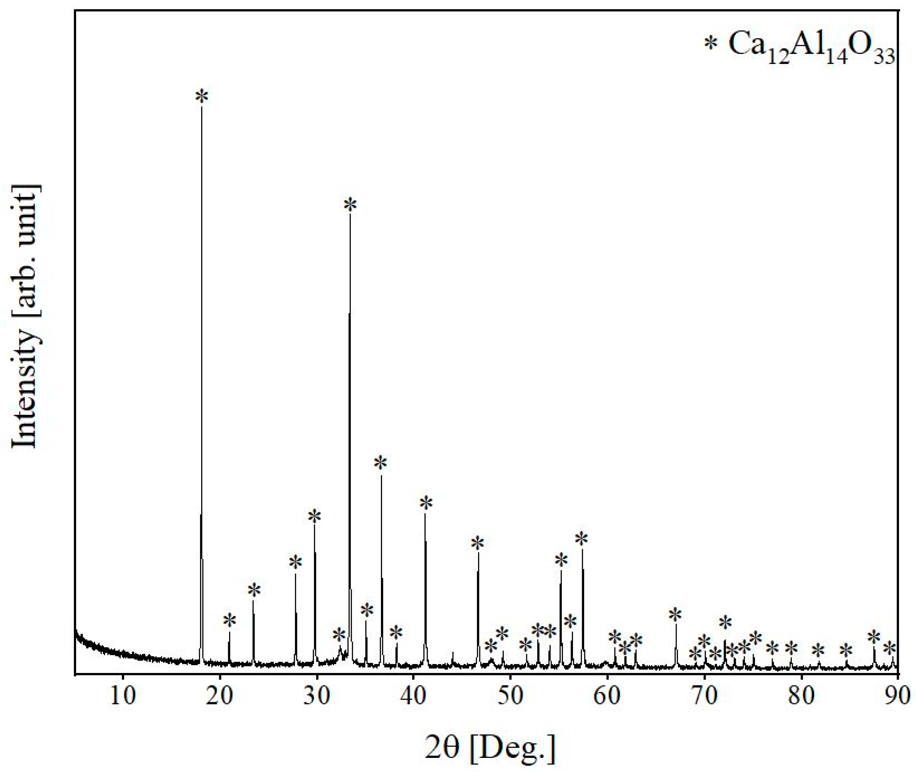
3.1. Reference Slag
3.2. Hot-Stage Microscopy Analysis
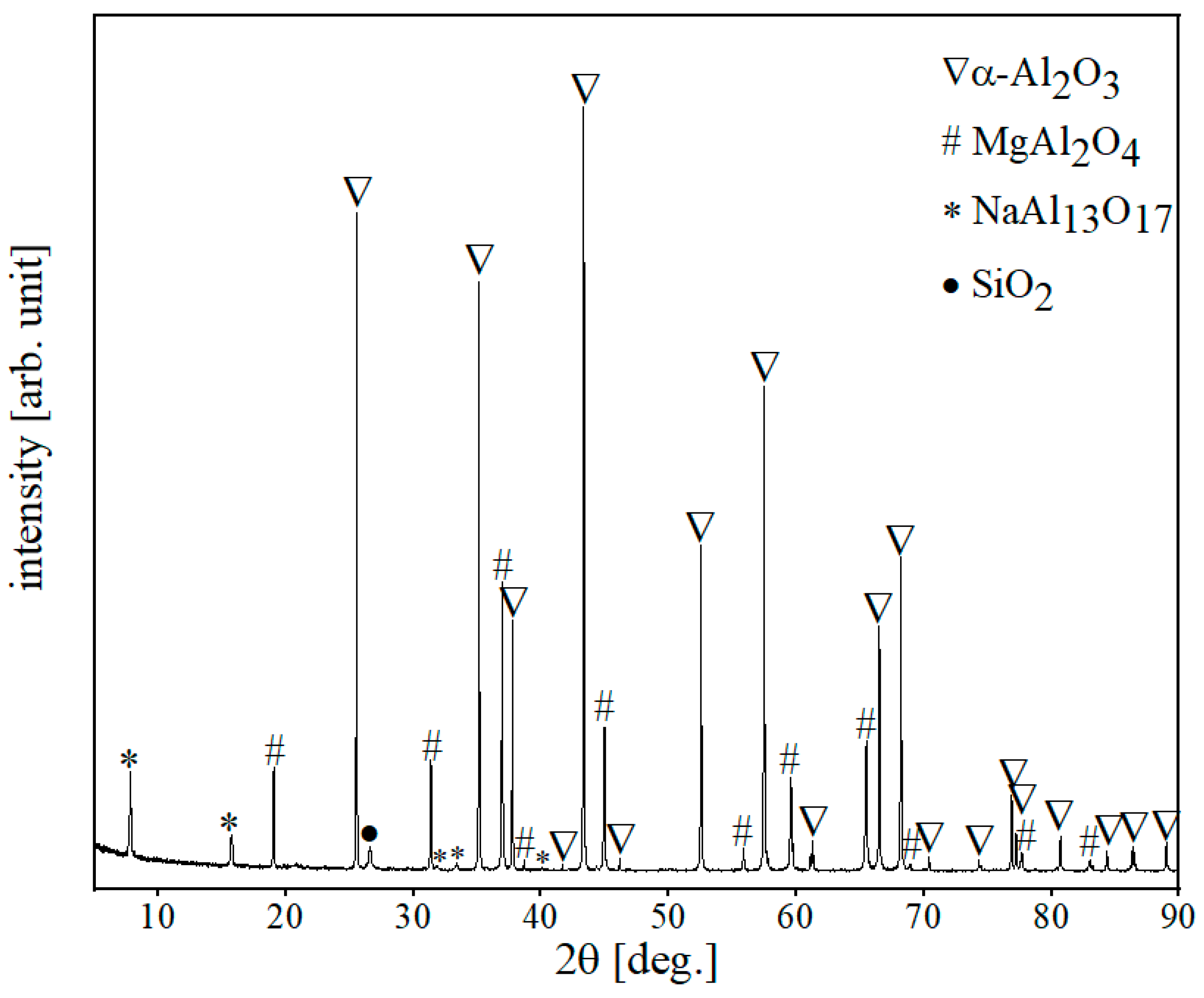
3.3. Alumina-Spinel Refractory
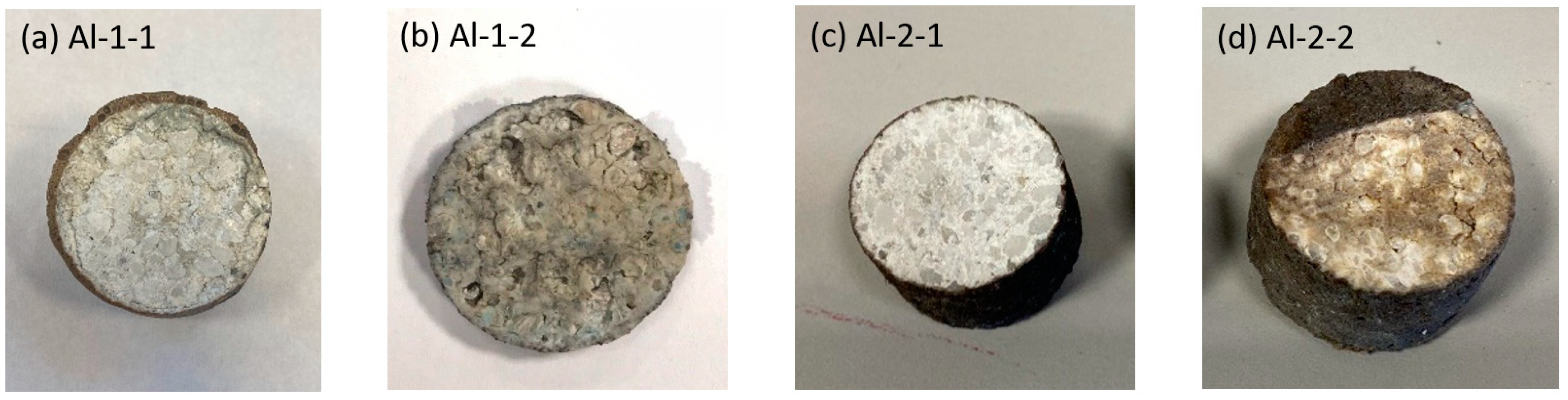
3.4. Alumina-Spinel Refractory after Corrosion Test
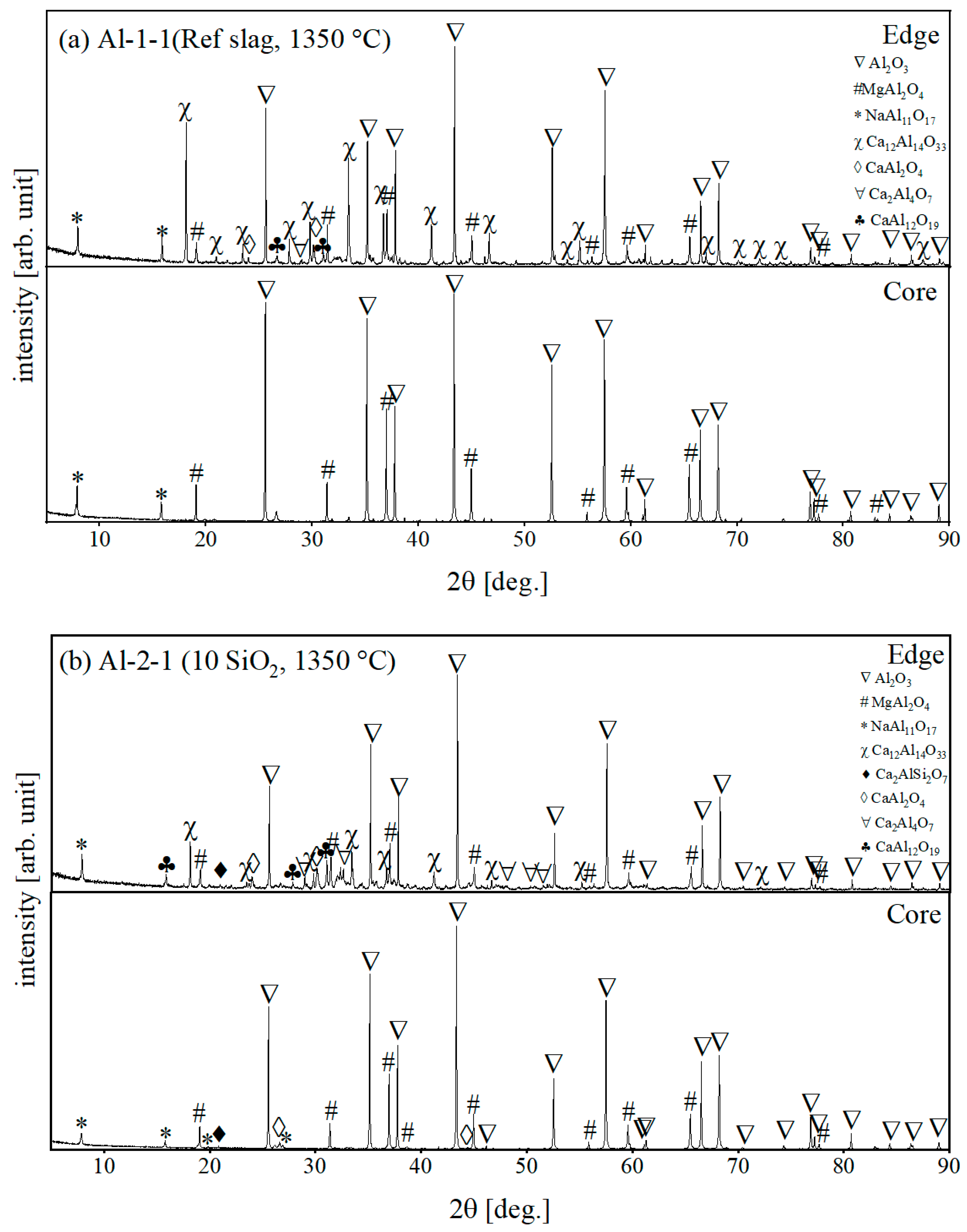
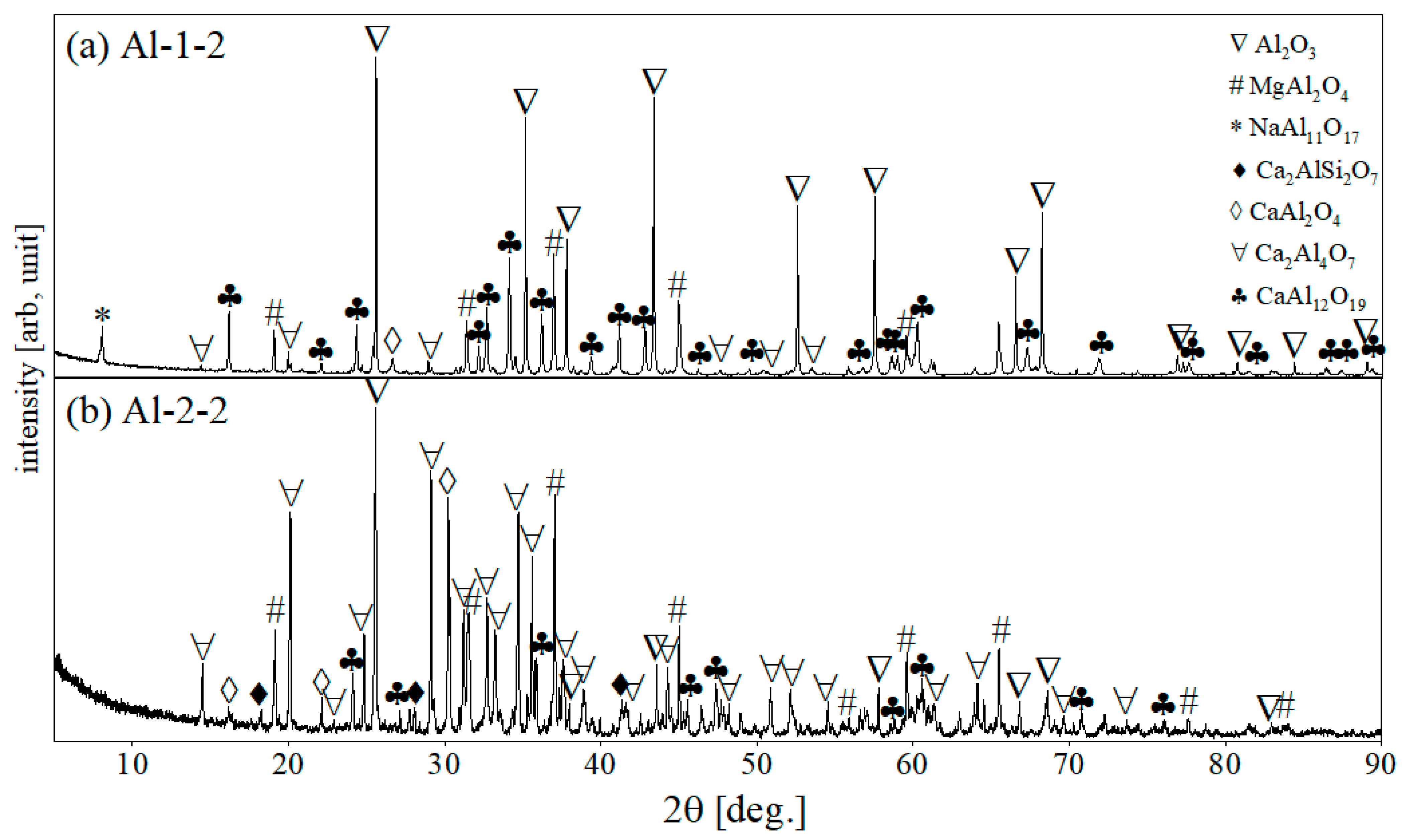
3.4.1. X-ray Diffractometry
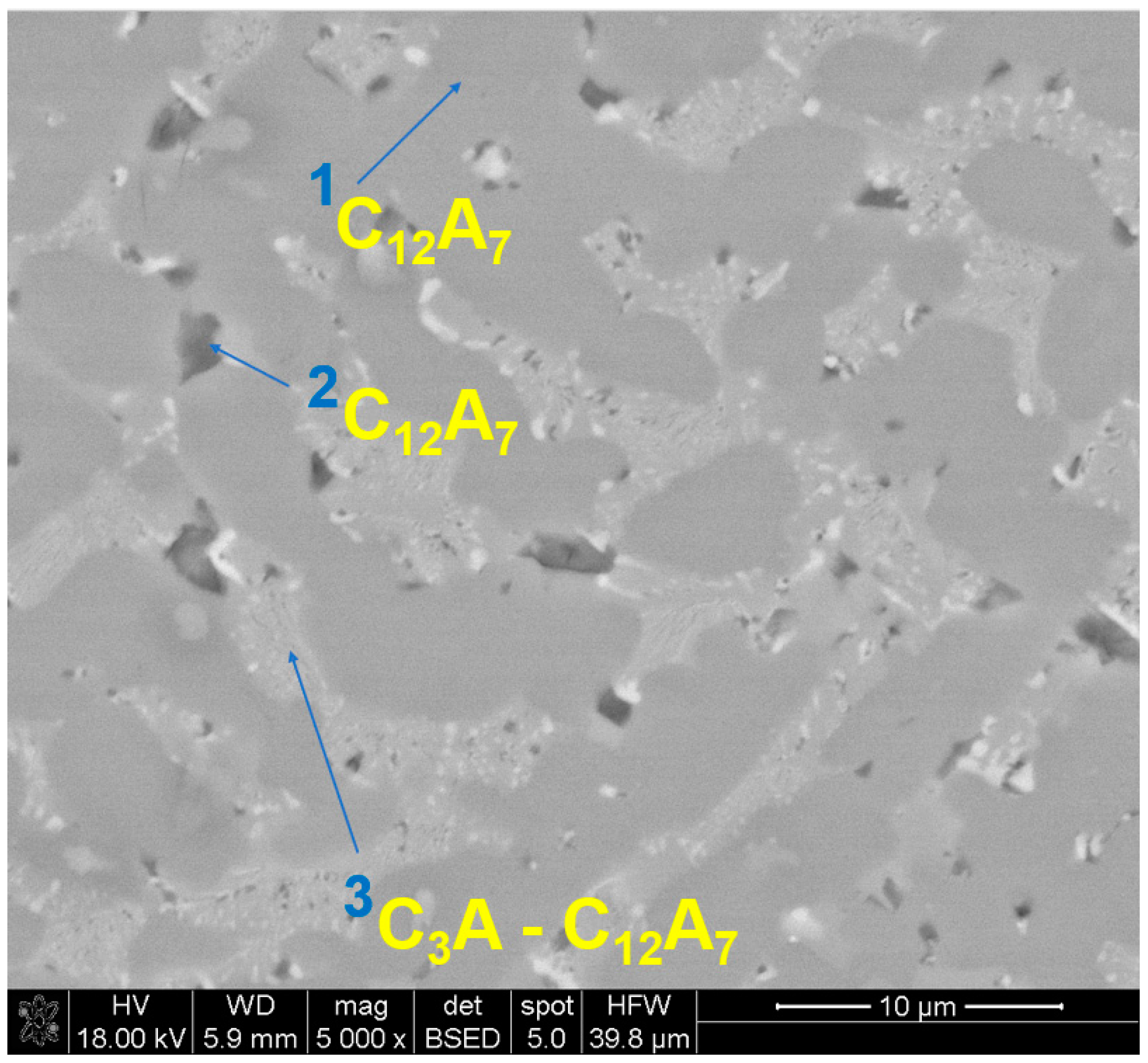
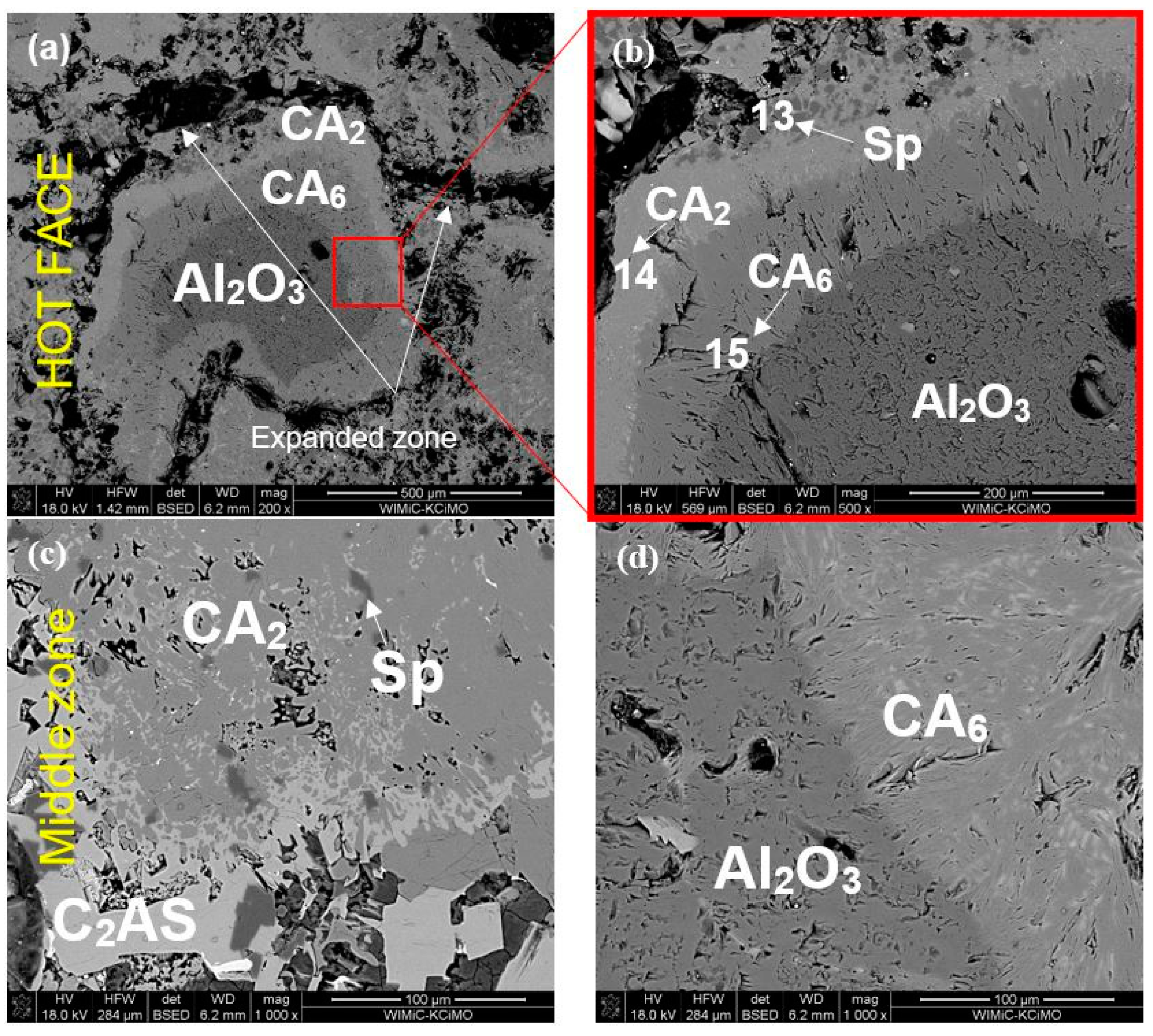
3.4.2. SEM/EDS Observations
4. Discussion
4.1. Slag Viscosity
4.2. Slag-Refractory Interactions
5. Conclusions
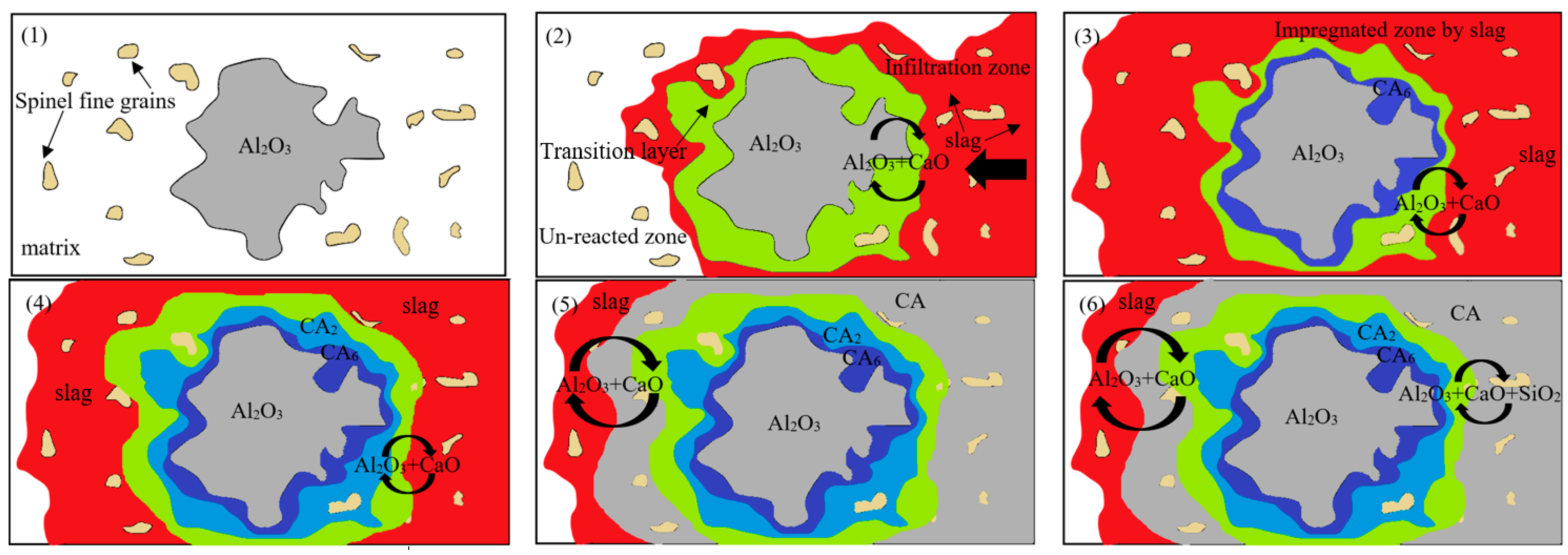
- The corrosion mechanism of alumina-spinel material tested against acid metallurgical slags is based on the indirect dissolution of alumina grains constituting the principal component of the refractory.
- The indirect dissolution of alumina covers the formation of new calcium aluminate layers around alumina grains, including CA2 and CA6, for both corrosive slags and heating at both 1350 °C and 1450 °C. By increasing the temperature to 1450 °C, the infiltration of refractory by slag increases; specifically, Ca2+ diffuses more intensively towards refractory followed by the formation of CA2 and CA6.
- CA6 forms in platelet morphology and by expansion causes loosening of the microstructure, especially at increased temperatures when its amount is doubled.
- The low melting phase of gehlenite, Ca2Al2SiO7, forms in phase composition of alumina-spinel samples corroded by both slags, and its amount is doubled for silica enriched S slag containing 10% SiO2.
Author Contributions
Funding
Institutional Review Board Statement
Informed Consent Statement
Data Availability Statement
Conflicts of Interest
References
- Kakroudi, M.G.; Vafa, N.P.; Asl, M.S.; Shokouhimehr, M. Effects of SiC content on thermal shock behavior and elastic modulus of cordierite—Mullite composites. Ceram. Int. 2020, 46, 23780–23784. [Google Scholar] [CrossRef]
- Darban, S.; Kakroudi, M.G.; Vandchali, M.B.; Vafa, N.P.; Rezaei, F.; Charkhesht, V. Characterization of Ni-doped pyrolyzed phenolic resin and its addition to the Al2O3–C refractories. Ceram. Int. 2020, 46, 20954–20962. [Google Scholar] [CrossRef]
- Schacht, C. Refractories Handbook; CRC Press: Boca Raton, FL, USA, 2004. [Google Scholar]
- Ganesh, I.; Bhattacharjee, S.; Saha, B.P.; Johnson, R.; Rajeshwari, K.; Sengupta, R.; Rao, M.R.; Mahajan, Y.R. An efficient MgAl2O4 spinel additive for improved slag erosion and penetration resistance of high-Al2O3 and MgO–C refractories. Ceram. Int. 2002, 28, 245–253. [Google Scholar] [CrossRef]
- Wang, Y.; Li, X.; Chen, P.; Zhu, B. Matrix microstructure optimization of alumina-spinel castables and its effect on high temperature properties. Ceram. Int. 2018, 44, 857–868. [Google Scholar] [CrossRef]
- Braulio, M.A.L.; Rigaud, M.; Buhr, A.; Parr, C.; Pandolfelli, V.C. Spinel-containing alumina-based refractory castables. Ceram. Int. 2011, 37, 1705–1724. [Google Scholar] [CrossRef]
- Reynaert, C.; Śnieżek, E.; Szczerba, J. Corrosion Tests for Refractory Materials Intended for the Steel Industry–A Review. Ceram.–Silikáty 2020, 64, 278–288. [Google Scholar] [CrossRef] [Green Version]
- Poirier, J.; Smith, J.D.; Jung, I.H.; Kang, Y.B.; Eustathopoulos, N.; Blond, É.; Rigaud, M. Corrosion of Refractories: The Fundamentals; Göller Verlag: Baden-Baden, Germany, 2017. [Google Scholar]
- Ludwig, M.; Wiśniewska, K.; Śnieżek, E.; Jastrzębska, I.; Prorok, R.; Szczerba, J. Effect of the chemical composition of slag on the corrosion of calcium zirconate material. Mater. Chem. Phys. 2021, 258, 123844. [Google Scholar] [CrossRef]
- Lee, W.E.; Zhang, S. Melt corrosion of oxide and oxide-carbon refractories. Int. Mater. Rev. 1999, 44, 77–104. [Google Scholar] [CrossRef]
- Song, J.; Liu, Y.; Lv, X.; You, Z. Corrosion Behavior of Al2O3 Substrate by SiO2–MgO–FeO–CaO–Al2O3 Slag. J. Mater. Res. Technol. 2020, 9, 314–321. [Google Scholar] [CrossRef]
- Braulio, M.A.L.; Martinez, A.T.; Luz, A.P.; Liebske, C.; Pandolfelli, V.C. Basic slag attack of spinel-containing refractory castables. Ceram. Int. 2011, 37, 1935–1945. [Google Scholar] [CrossRef]
- Martinez, A.T.; Luz, A.P.; Braulio, M.A.L.; Pandolfelli, V.C. CA6 impact on the corrosion behavior of cement-bonded spinel-containing refractory castables: An analysis based on thermodynamic simulations. Ceram. Int. 2015, 41, 4714–4725. [Google Scholar] [CrossRef]
- Madej, D.; Szczerba, J. Detailed studies on microstructural evolution during the high temperature corrosion of SiC-containing andalusite refractories in the cement kiln preheater. Ceram. Int. 2017, 43, 1988–1996. [Google Scholar] [CrossRef]
- Jing, S.-Y.; Lin, L.-B.; Huang, N.-K.; Zhang, J.; Lu, Y. Investigation on lattice constants of Mg-Al spinels. J. Mater. Sci. Lett. 2000, 19, 225–227. [Google Scholar] [CrossRef]
- Poirier, J.; Bouchetou, M.L. Corrosion of refractories, measurements and thermodynamic modeling. In Proceedings of the 10th International Conference of European Ceramic Society, Berlin, Germany, 17–21 June 2007; pp. 7–21. [Google Scholar]
- Khajornboon, J.; Ota, K.; Washijima, K.; Shiono, T. Control of hexagonal plate-like microstructure of in-situ calcium hexaluminate in monolithic refractories. J. Asian Ceram. Soc. 2018, 6, 196–204. [Google Scholar] [CrossRef]
- Sarpoolaky, H.; Zhang, S.; Argent, B.B.; Lee, W.E. Influence of grain phase on slag corrosion of low-cement castable refractories. J. Am. Ceram. Soc. 2001, 84, 426–434. [Google Scholar] [CrossRef]
- Luz, A.P.; Martinez, A.T.; Braulio, M.A.L.; Pandolfelli, V.C. Thermodynamic evaluation of spinel containing refractory castables corrosion by secondary metallurgy slag. Ceram. Int. 2011, 37, 1191–1201. [Google Scholar] [CrossRef]
- Herasymenko, P. Electrochemical theory of slag-metal equilibria. Part I.—Reactions of manganese and silicon in acid open-heart furnace. Trans. Faraday Soc. 1938, 34, 1245–1254. [Google Scholar] [CrossRef]
- Çelikbilek, M.; Ersundu, A.E.; Aydın, S. Crystallization kinetics of amorphous materials. Adv. Cryst. Process. 2012, 35347, 127–162. Available online: https://books.google.co.jp/books?hl=zh-TW&lr=&id=4NqgDwAAQBAJ&oi=fnd&pg=PA127&dq=Crystallization+kinetics+of+amorphous+materials&ots=EiOAFn5HDL&sig=cXwDHgQxj1PfmhsSLn4LHR-1uGE&redir_esc=y#v=onepage&q=Crystallization%20kinetics%20of%20amorphous%20materials&f=false (accessed on 4 May 2022).
- De Bilbao, E.; Dombrowski, M.; Pilliere, H.; Poirier, J. Time-resolved high-temperature X-ray diffraction for studying the kinetics of corrosion of high-alumina refractory by molten oxides. Corros. Sci. 2018, 139, 346–354. [Google Scholar] [CrossRef]
- De Bilbao, E.; Dombrowski, M.; Traon, N.; Tonnesen, T.; Poirier, J.; Blond, E. Study of Reactive Impregnation and Phase Transformations During the Corrosion of High Alumina Refractories by Al2O3-CaO Slag. In Advances in Science and Technology; Trans Tech Publications Ltd.: Bäch, Switzerland, 2014; Volume 92, pp. 264–271. [Google Scholar]
- Sako, E.Y.; Braulio, M.A.L.; Milanez, D.H.; Brant, P.O.; Pandolfelli, V.C. Microsilica role in the CA6 formation in cement-bonded spinel refractory castables. J. Mater. Process. Technol. 2009, 209, 5552–5557. [Google Scholar] [CrossRef]
- Hasegawa, M. Thermodynamic Basis for Phase Diagrams. In Treatise on Process Metallurgy; Elsevier: Amsterdam, The Netherlands, 2014; pp. 527–556. [Google Scholar]
- Zhang, S.; Rezaie, H.R.; Sarpoolaky, H.; Lee, W.E. Alumina dissolution into silicate slag. J. Am. Ceram. Soc. 2000, 83, 897–903. [Google Scholar] [CrossRef]


| Component (wt.%) | R Slag | S Slag |
|---|---|---|
| CaO | 48.5 | 45.6 |
| Al2O3 | 40.9 | 38.4 |
| SiO2 | 4.20 | 10.0 |
| Fe2O3 | 2.20 | 2.10 |
| TiO2 | 1.90 | 1.80 |
| MgO | 0.60 | 0.60 |
| P2O5 | 0.47 | 0.42 |
| SO3 | 0.40 | 0.38 |
| K2O | 0.33 | 0.29 |
| Cr2O3 | 0.05 | 0.05 |
| MnO | 0.08 | 0.05 |
| SrO | 0.05 | 0.04 |
| ZrO2 | 0.09 | 0.08 |
| Na2O | 0.21 | 0.18 |
| Cl | 0.02 | 0.01 |
| Element | Chemical Composition by XRF (wt.%) |
|---|---|
| Al2O3 | 87.7 |
| MgO | 5.8 |
| SiO2 | 4.8 |
| Na2O | 0.5 |
| Fe2O3 | 0.3 |
| CaO | 0.2 |
| Others | 0.8 |
| Bulk density (g/cm3) | 3.08 |
| Apparent porosity (%) | 18.42 |
| Sample Name | Slag Type | Temperature (°C) | Dwell Time (h) | Atmosphere |
|---|---|---|---|---|
| Al-1-1 | R | 1350 | 10 | Oxidizing (air) |
| Al-1-2 | R | 1450 | 10 | |
| Al-2-1 | S | 1350 | 10 | |
| Al-2-2 | S | 1450 | 10 |
| Point | Chemical Composition by EDS, at.% * | Ratio Ca/Al ** | Phase | |||||
|---|---|---|---|---|---|---|---|---|
| Ca | Al | Si | Mg | Ti | Fe | |||
| 1 | 21.6 | 38.4 | 0.3 | 0.1 | - | - | 0.6 | C12A7 |
| 2 | 22.6 | 35.4 | 2.3 | 0.3 | 0.9 | - | 0.6 | C12A7 |
| 3 | 25.1 | 22.9 | 7.2 | 0.8 | 2.8 | 1.5 | 1.1 | C3A-C12A7 |
| Point | Element (at.%) * | |
|---|---|---|
| Mg | Al | |
| 1 | - | 53 |
| 2 | 13.8 | 45.5 |
| Point | Elemental Composition (at.%) * | Assigned Phase | ||||
|---|---|---|---|---|---|---|
| Mg | Al | Si | Ca | Ti | ||
| 1 | 0.27 | 38.36 | - | 23.11 | - | CA |
| 2 | - | 52 | - | - | - | Al2O3 |
| 3 | 1.05 | 50.04 | - | 4.38 | - | CA6 |
| 4 | 17.11 | 42.05 | - | 0.37 | - | Sp |
| 5 | 2.38 | 51.38 | - | 5.96 | - | CA6 |
| 6 | 16.27 | 41.65 | - | 0.29 | - | Sp |
| 7 | 0.93 | 43.99 | 45 | 13.17 | - | CA2 |
| 8 | 1.03 | 46.45 | 0.56 | 4.37 | - | CA6 |
| 9 | 1.43 | 15.24 | 5.95 | 13.30 | 3.03 | C2AS |
| 10 | 0.70 | 34.48 | 0.44 | 14.40 | - | CA |
| 11 | - | 37.18 | - | 8.23 | - | CA2 |
| 12 | - | 41.83 | - | 2.99 | - | CA6 |
| 13 | 15.69 | 40.88 | - | - | - | MA |
| 14 | - | 41.18 | - | 13.87 | - | CA2 |
| 15 | - | 49.27 | - | 5.09 | - | CA6 |
| Slag | 1350 °C | 1450 °C | ||||
|---|---|---|---|---|---|---|
| CA6 | CA2 | C2AS | CA6 | CA2 | C2AS | |
| R slag | 23.6 | 40.6 | 6.2 | 36.5 | 40.9 | 6.1 |
| S slag | 24.6 | 38.5 | 11.5 | 49.5 | 25.3 | 10.6 |
Publisher’s Note: MDPI stays neutral with regard to jurisdictional claims in published maps and institutional affiliations. |
© 2022 by the authors. Licensee MDPI, Basel, Switzerland. This article is an open access article distributed under the terms and conditions of the Creative Commons Attribution (CC BY) license (https://creativecommons.org/licenses/by/4.0/).
Share and Cite
Darban, S.; Reynaert, C.; Ludwig, M.; Prorok, R.; Jastrzębska, I.; Szczerba, J. Corrosion of Alumina-Spinel Refractory by Secondary Metallurgical Slag Using Coating Corrosion Test. Materials 2022, 15, 3425. https://doi.org/10.3390/ma15103425
Darban S, Reynaert C, Ludwig M, Prorok R, Jastrzębska I, Szczerba J. Corrosion of Alumina-Spinel Refractory by Secondary Metallurgical Slag Using Coating Corrosion Test. Materials. 2022; 15(10):3425. https://doi.org/10.3390/ma15103425
Chicago/Turabian StyleDarban, Sina, Camille Reynaert, Maciej Ludwig, Ryszard Prorok, Ilona Jastrzębska, and Jacek Szczerba. 2022. "Corrosion of Alumina-Spinel Refractory by Secondary Metallurgical Slag Using Coating Corrosion Test" Materials 15, no. 10: 3425. https://doi.org/10.3390/ma15103425
APA StyleDarban, S., Reynaert, C., Ludwig, M., Prorok, R., Jastrzębska, I., & Szczerba, J. (2022). Corrosion of Alumina-Spinel Refractory by Secondary Metallurgical Slag Using Coating Corrosion Test. Materials, 15(10), 3425. https://doi.org/10.3390/ma15103425