
Influence of Thermal Shocks on Residual Static Strength, Impact Strength and Elasticity of Polymer-Composite Materials Used in Firefighting Helmets

 ,
,  , , and
Abstract
:1. Introduction
2. Research Method
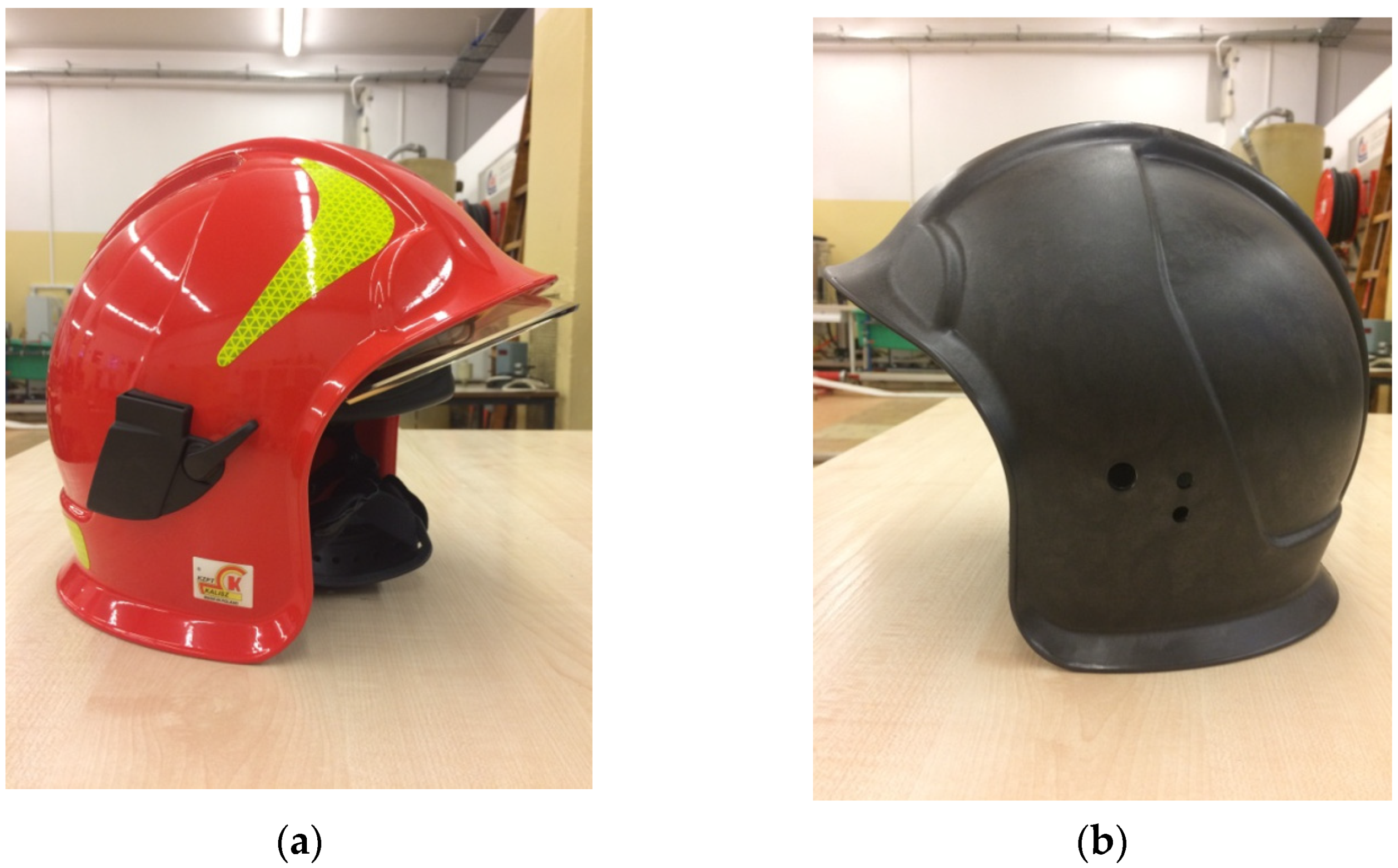
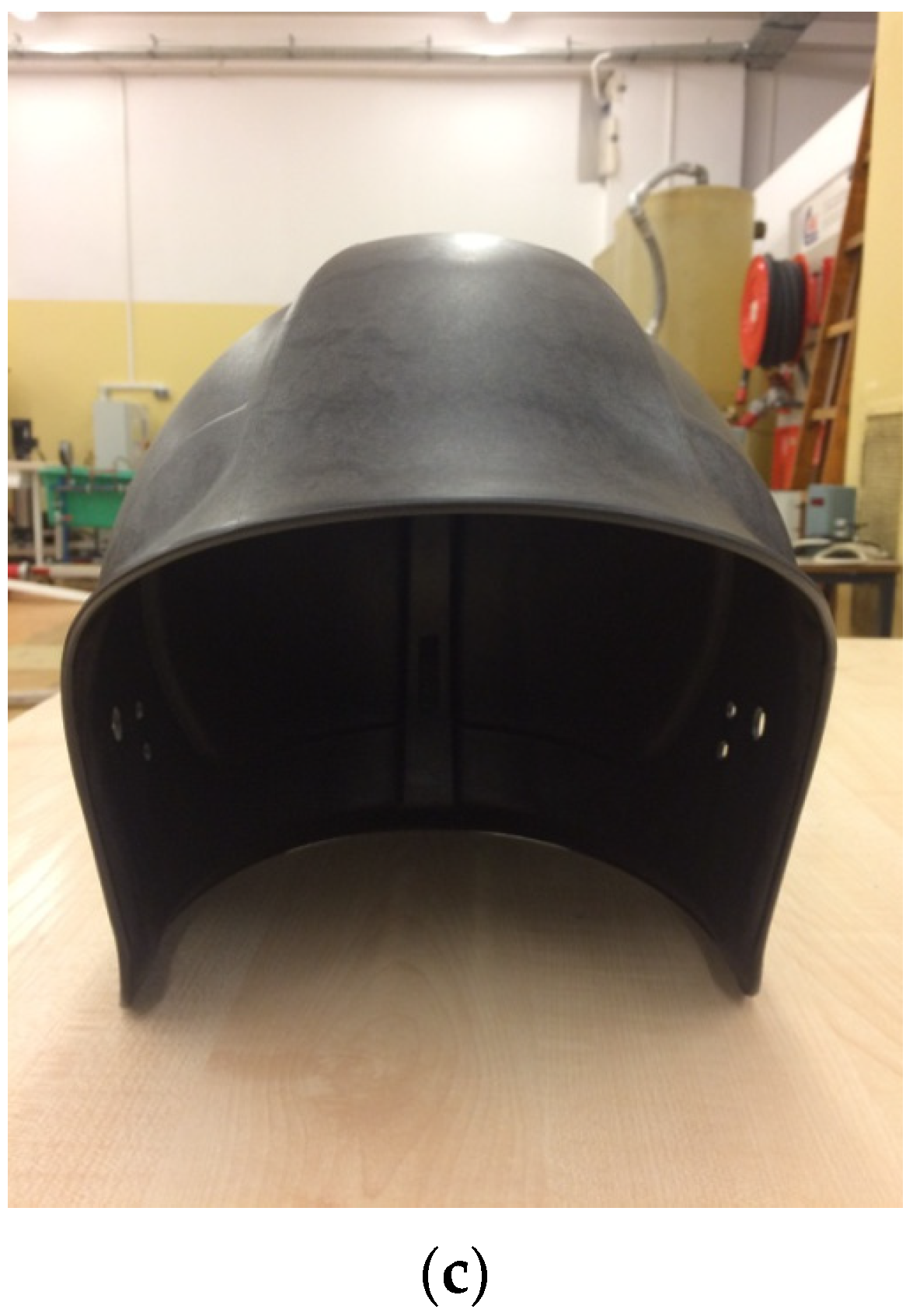
2.1. Materials
2.2. Static and Impact Strength Tests
2.2.1. Static Tensile Strength Testing Method
- —tensile strength (MPa);
- —maximum force (N);
- —initial cross-sectional area of the sample (mm2).
- —Young’s modulus (MPa);
- —the slope of the tangent line to stress-strain diagram.
- —work of stretching (Nmm);
- —test loading (N);
- —initial sample length (mm);
- —sample elongation (mm).
2.2.2. Static Bending Strength Testing Method
- —test loading (N);
- —distance between supports (mm);
- —sample width (mm);
- —sample thickness (mm).
- —slope of the diagram in a linear scope;
- —distance between supports (mm);
- —sample width (mm);
- —sample thickness (mm).
2.2.3. Shock Bending Strength Test
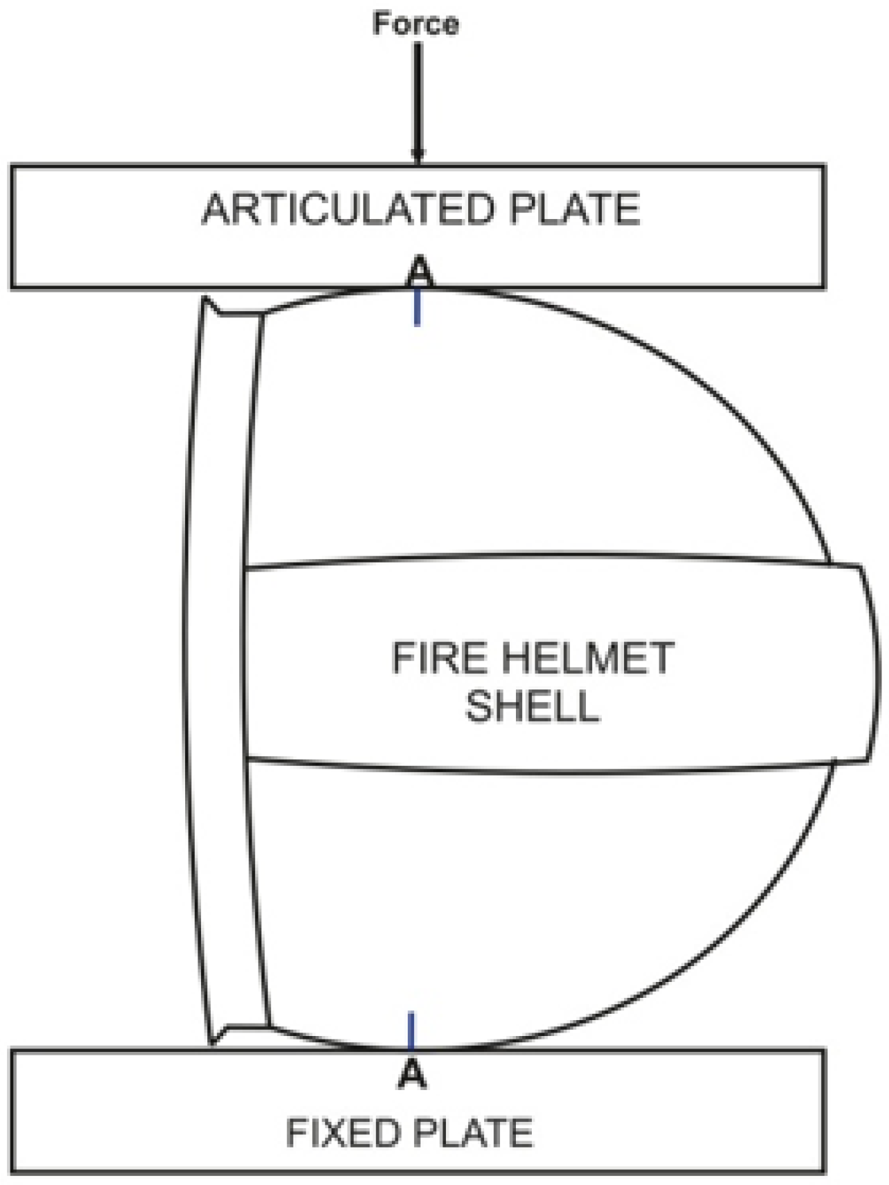
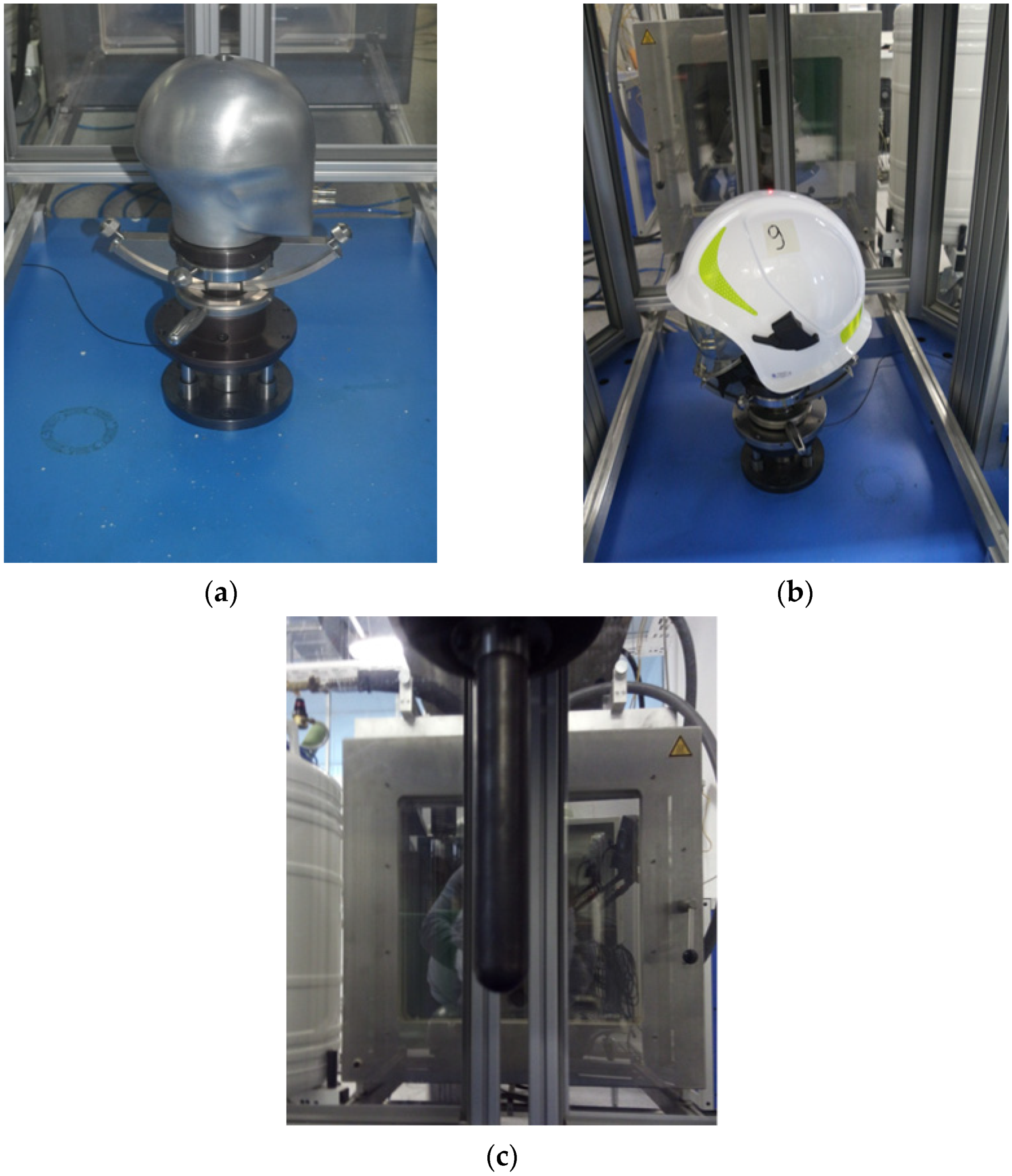
2.3. Testing Lateral Stiffness of Helmet Shells
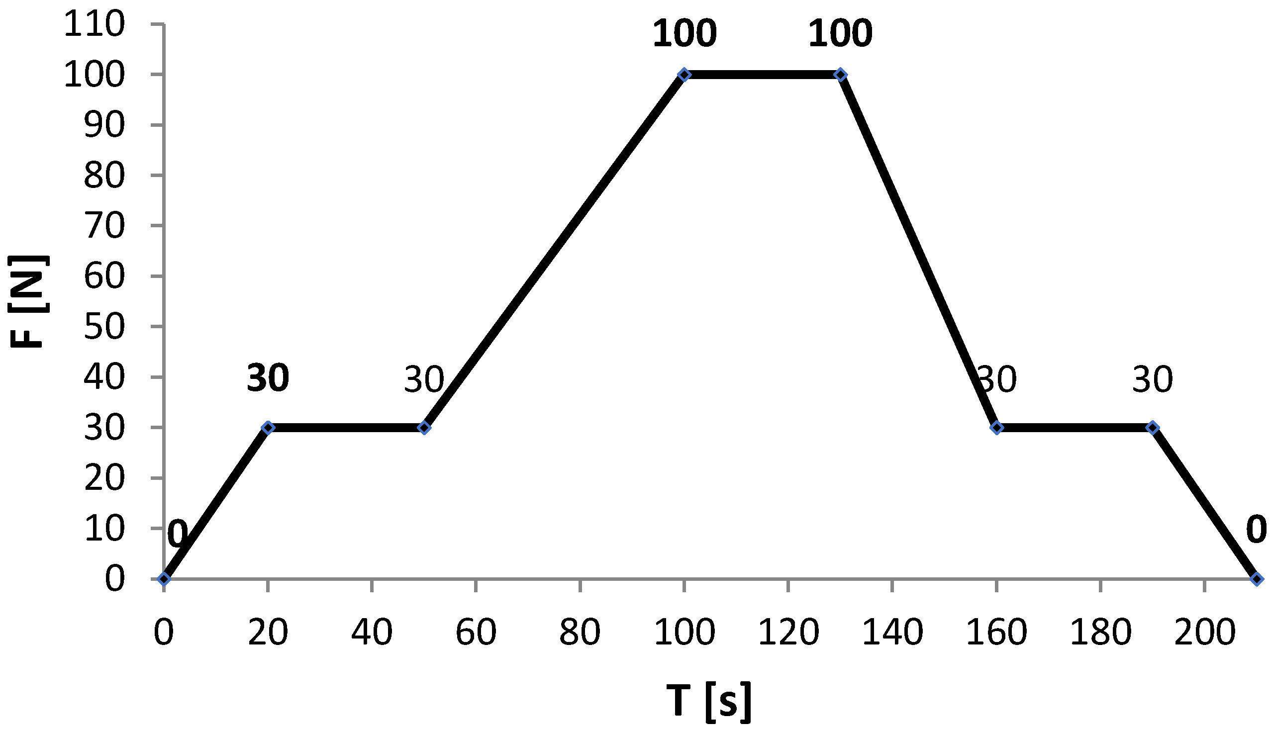
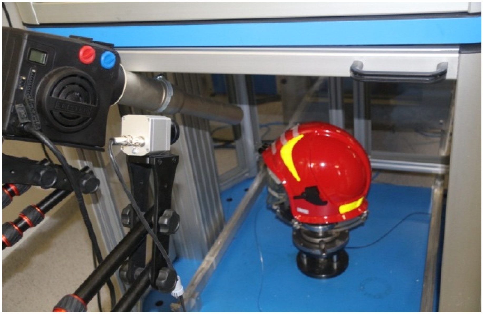
2.4. Testing the Influence of Treating a Firefighting Helmet with a Spherical Impactor
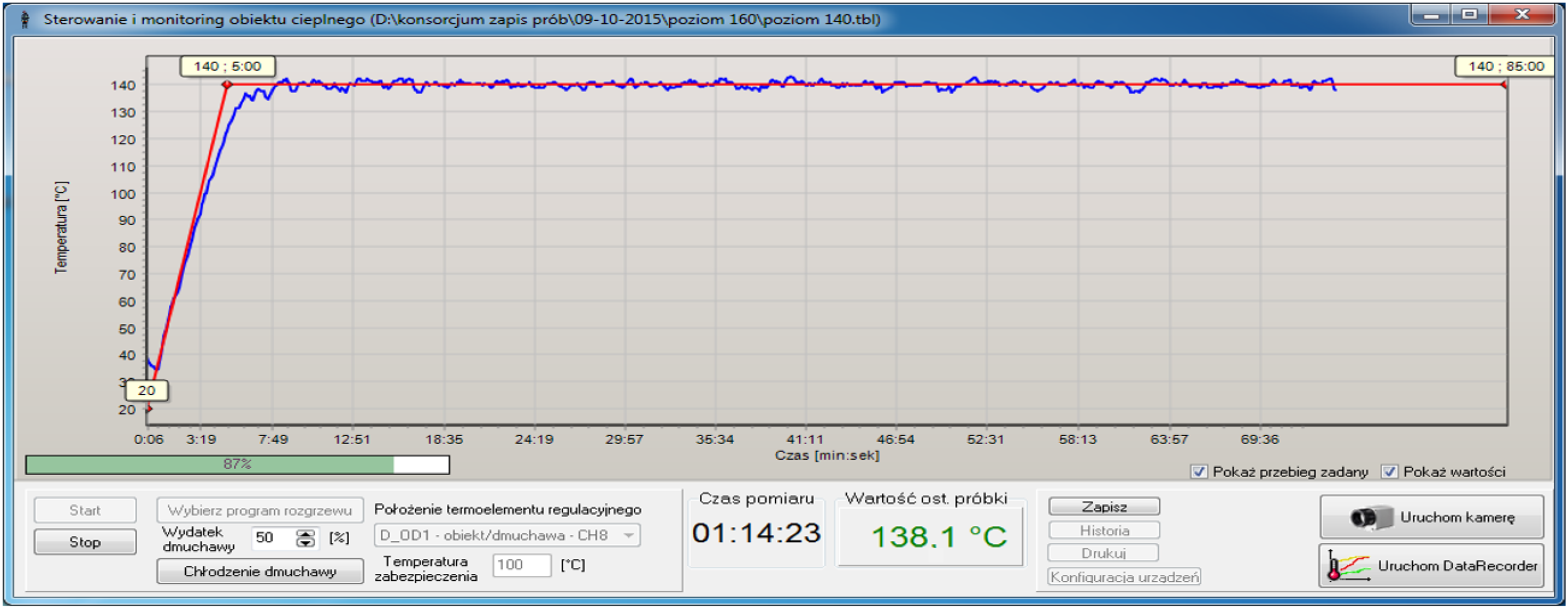
2.5. Thermal Shock Loading
2.5.1. Cyclic Thermal Shock Loading
2.5.2. Thermal Shock Load in the Impact Strength, Bending and Lateral Stiffness Tests
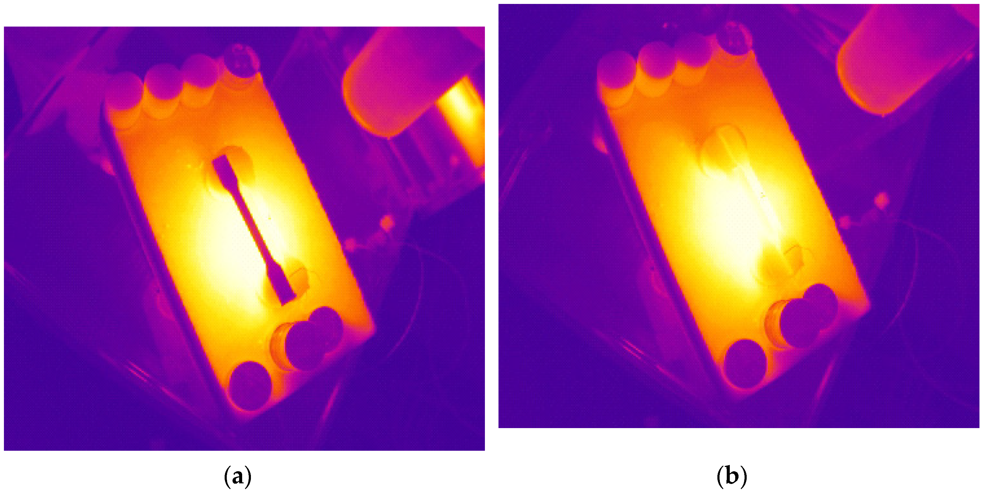
2.5.3. Thermal Shock Load in the Test of Treating a Firefighting Helmet with a Spherical Impactor
3. Test Results
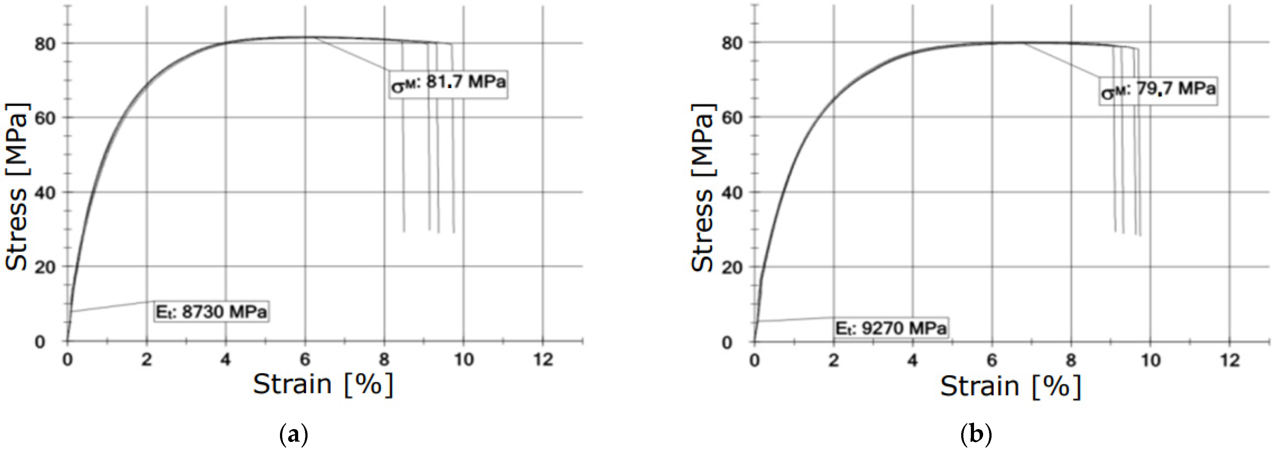
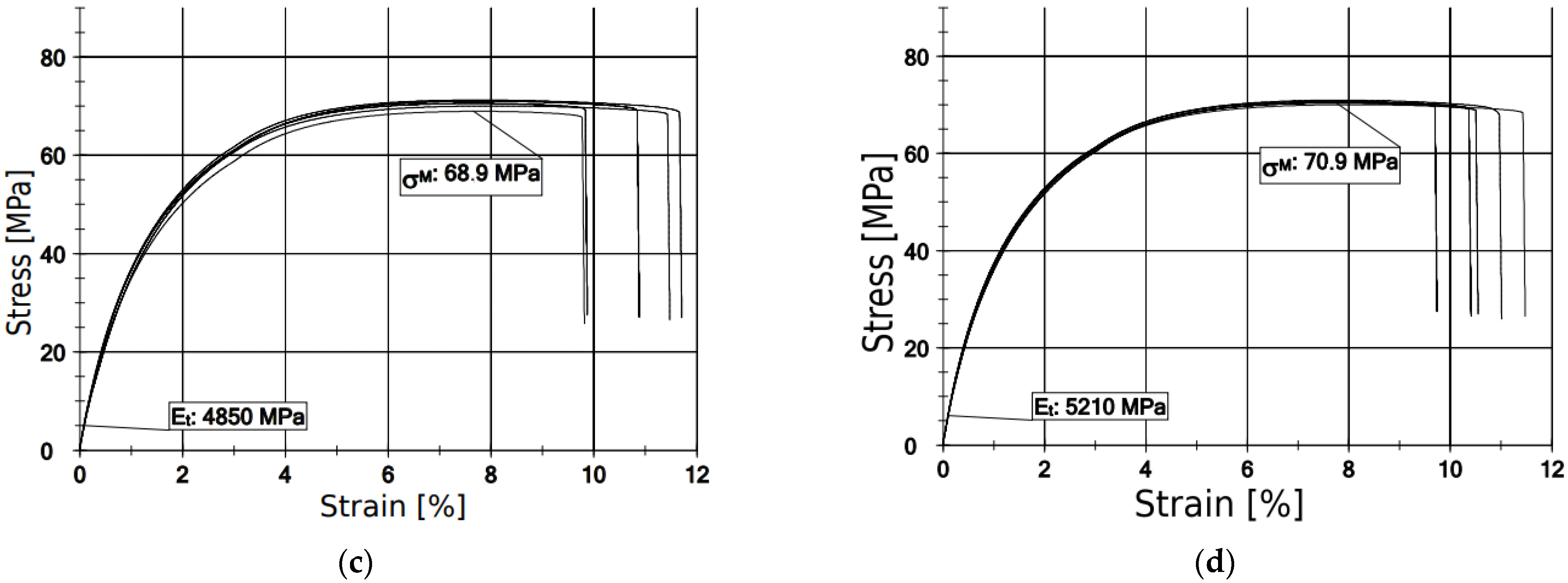
3.1. Results of Static Residual Tensile Strength Tests after Cyclic Thermal Shocks
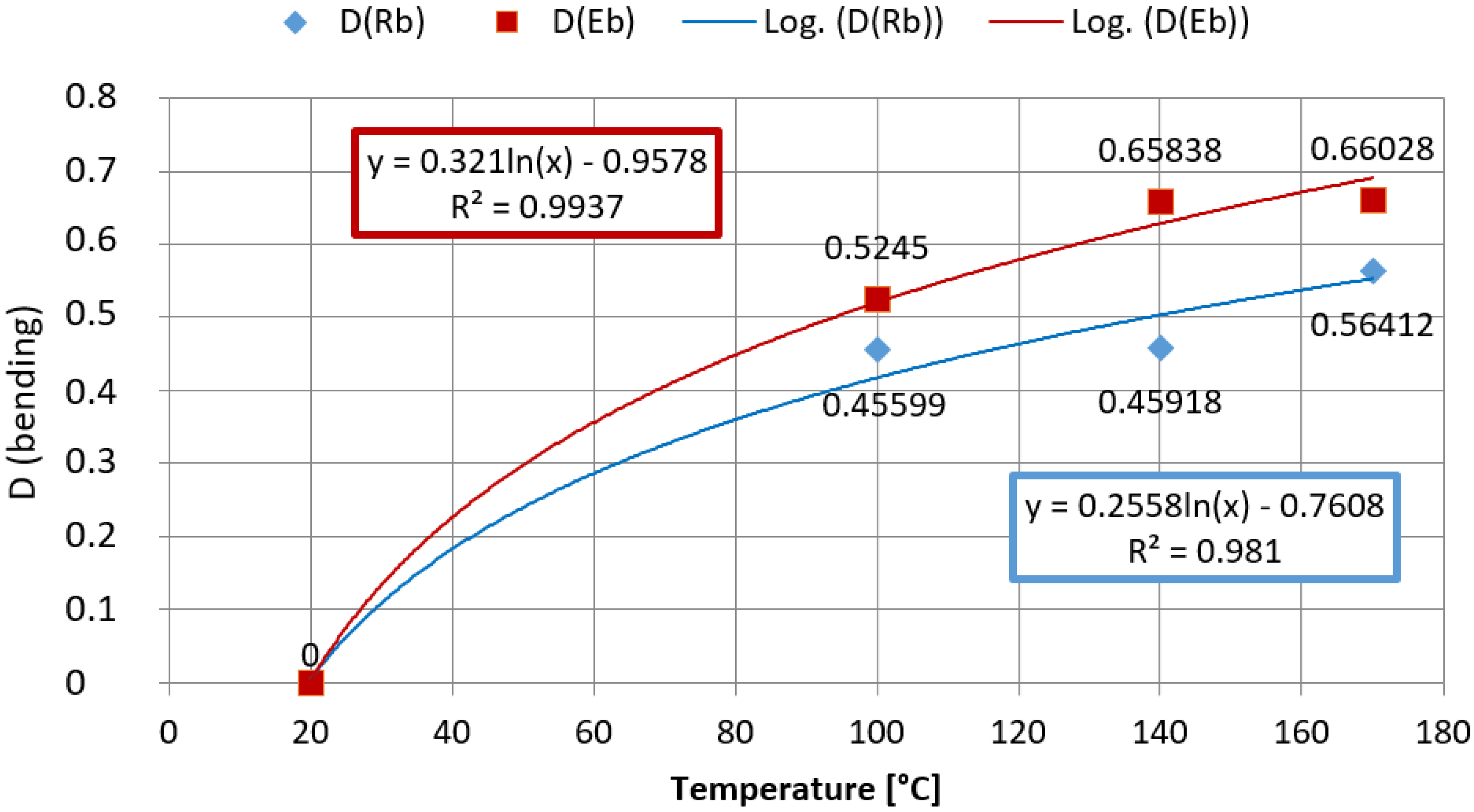
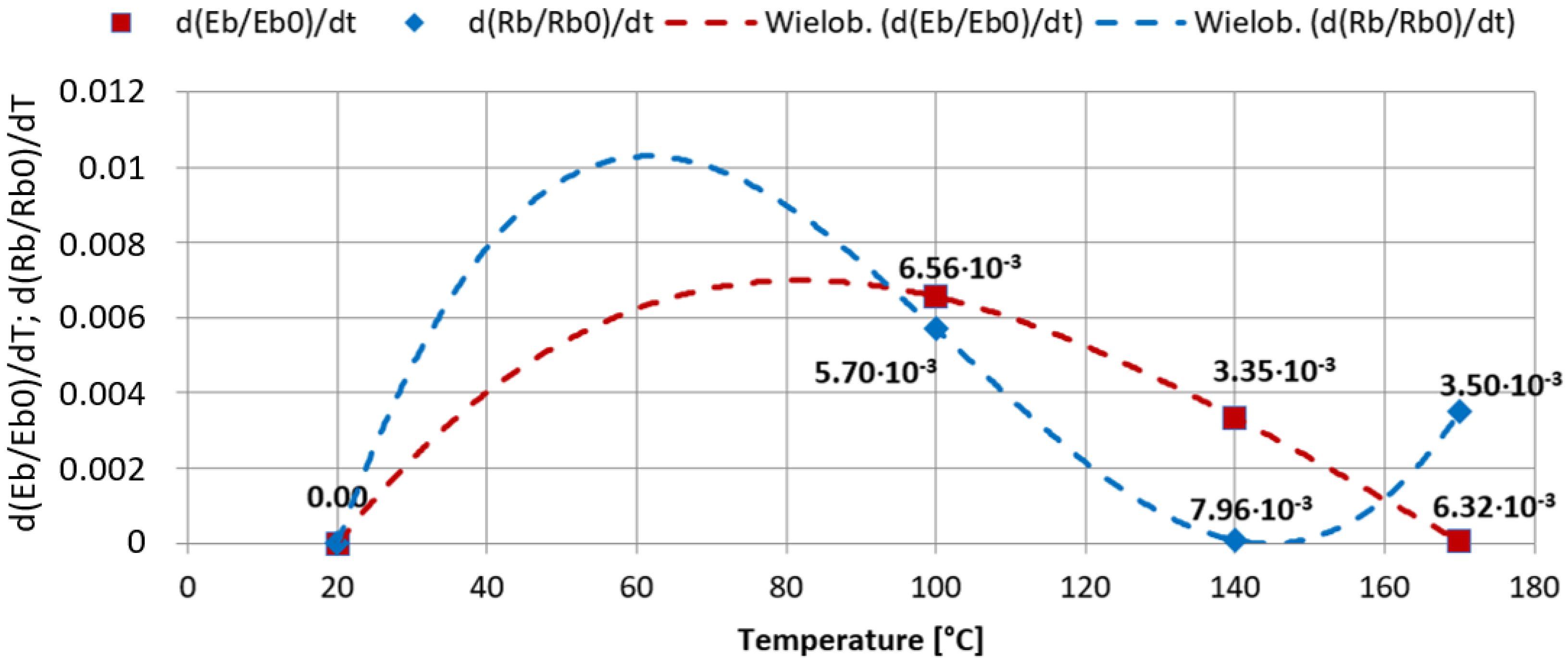
3.2. Results of Bending Strength Tests
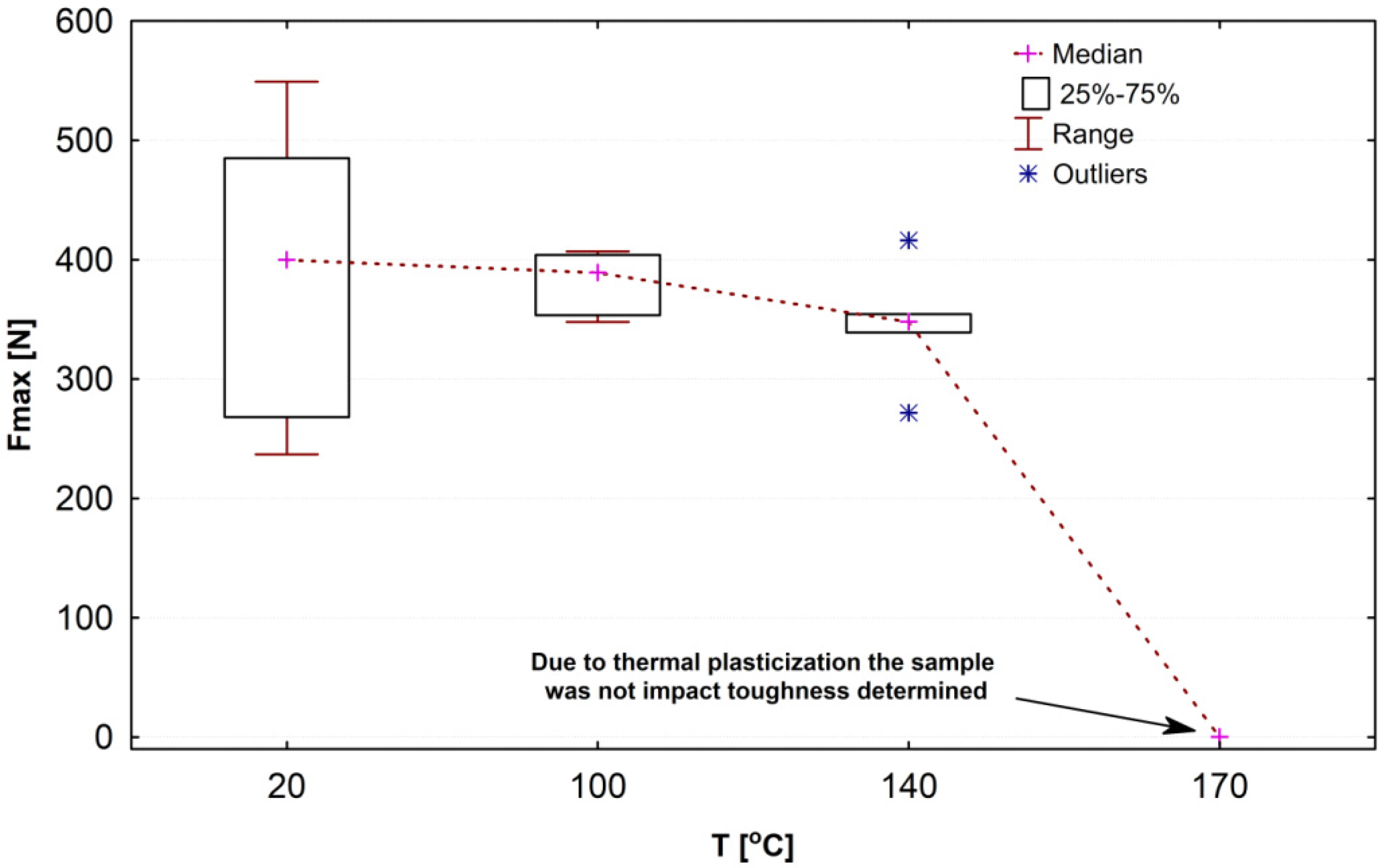
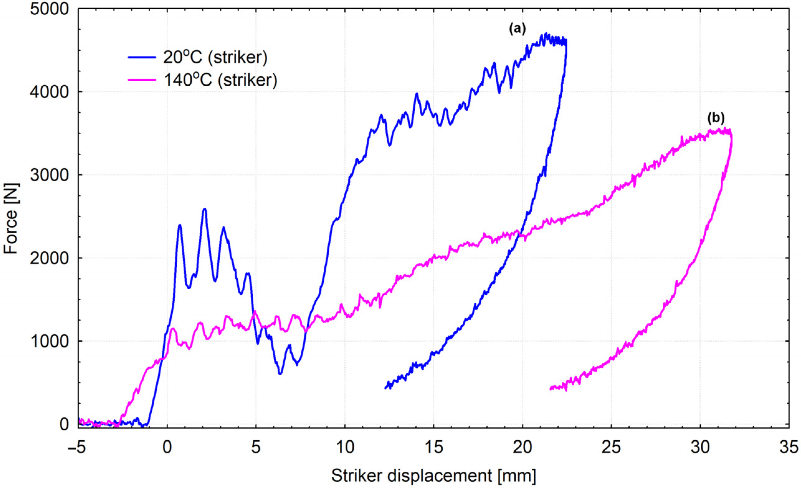
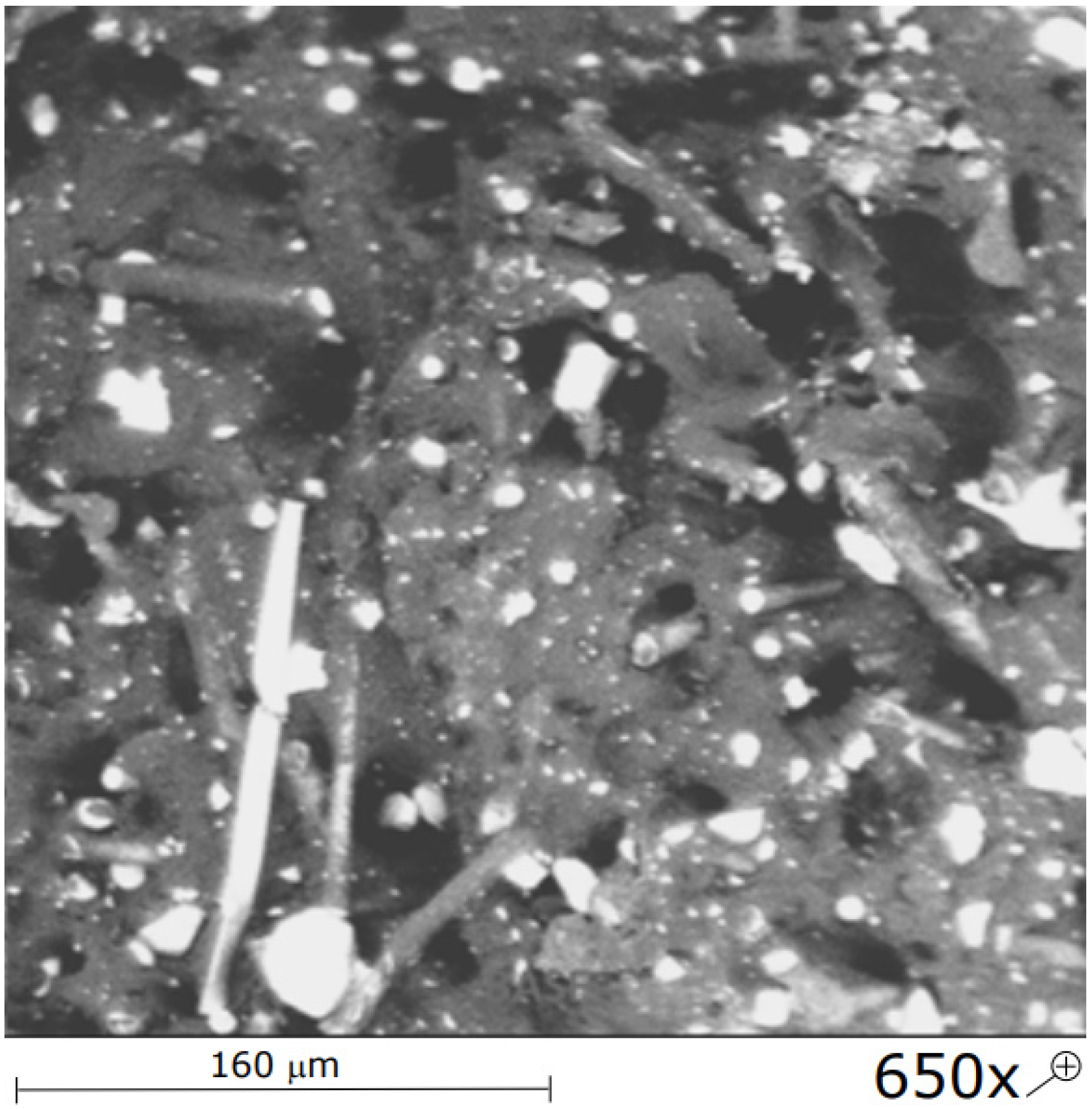
3.3. Results of Impact Strength Tests
3.4. Results of Stiffness Tests of Firefighting Helmet Shells
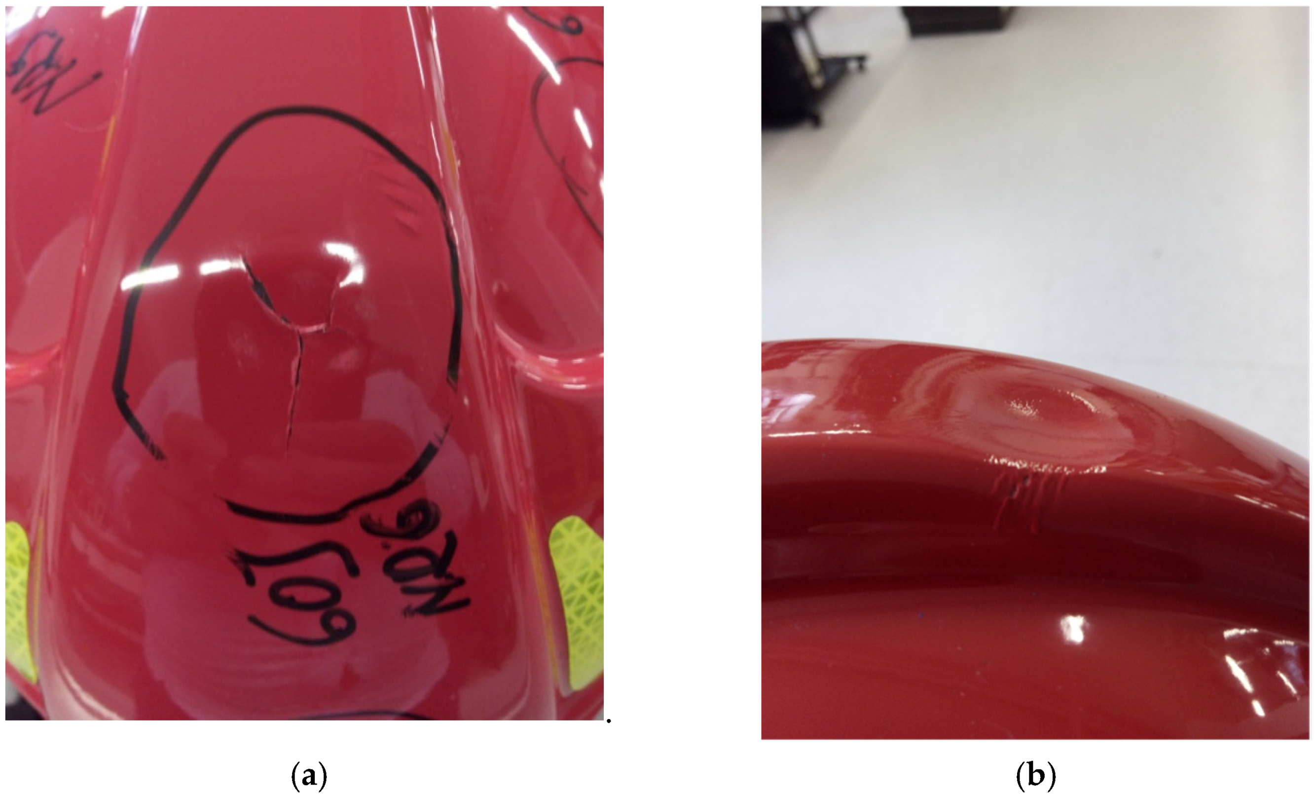
3.5. Helmet Impact Test Results
4. Discussion
4.1. Static Tensile Strength Tests (Cyclic Thermal Shocks)
4.2. Static Tensile Strength in Operating Temperature Value
- —the level of strength damage (D = 0 for reference samples tested at the temperature of 20 °C, without thermal damages);
- R—strength value obtained in a given temperature and time range of a thermal shock;
- R0—strength value for reference samples tested at the temperature of 20 °C;
- DE—the level of stiffness damage (D = 0 for reference samples tested at the temperature of 20 °C, without thermal damages);
- E—elastic modulus obtained in a given temperature and time range of a thermal shock;
- E0—elastic modulus for reference samples tested at the temperature of 20 °C.
- VR, VE—speed of damage of strength/elastic modulus depending on the temperature increase (VR and VE = 0 for reference samples tested at the temperature of 20 °C, without thermal damages);
- R—strength value obtained in a given temperature and time range of a thermal shock;
- R0—strength value for reference samples tested at the temperature of 20 °C;
- E—elastic modulus obtained in a given temperature and time range of a thermal shock;
- E0—elastic modulus for reference samples tested at the temperature of 20 °C;
- T—temperature (°C).
4.3. Impact Strength in Operating Temperature Values
4.4. Lateral Stiffness of a Helmet Shell
4.5. Helmet Impact Test Results
5. Summary
- The studied helmet model is commonly used by fire brigade units in Poland. Moreover, it is exported to many countries. Considering the above and the fact that there have been few studies concerning damages that occur during the maintenance of firefighting helmets, the test results presented in the article are of great significance;
- Thermal shocks in the extent compatible with thermal hazards that occur during fire and rescue operations (elevated temperature and/or cyclic thermal loads) cause significant changes in strength and elastic properties of the composite that the studied helmet is made of. After five thermal cycles with the highest shock temperature, the remaining average strength decreased by 13.36% and the modulus of elasticity by 40.92%. The average bending strength during the 170 degree Celsius shock dropped 56.41% from the room temperature strength and the modulus of elasticity by 66.03%, respectively. Under these thermal conditions, the impact strength was lost, and the lateral deflection of the helmet shells increased by 306.56%;
- It was confirmed that changes in mechanical and elastic properties of the shell composite can have an impact on the protective properties of the whole helmet;
- In the light of conducted experimental studies, the authors of the work propose systematizing damages caused by thermal factors. Based on classifications that can be found in specialized literature [47,48,49,50,51] and the opinion of authors of the following work, they may be divided into two groups: (a) occasional damages that occur in elevated temperatures that are close to or exceed characteristic temperatures of the material a shell is made of (e.g., softening temperature) that cause unacceptable deterioration of properties of a helmet shell, deformations and melting the material; (b) aging damages that occur as a result of regular participation in firefighting operations and that allow continuous or controlled functioning. Recurring situations in which a helmet is exposed to non-critical temperature cause systematic loss of properties;
- Using computer simulation tools (e.g., S-Dyna, PamCrash, HUMOS) that allow analyzing the behavior of helmets in simulations, e.g., using virtual anthropometric test dummies [8], requires having proper knowledge about helmet parameters. Thus, determining the properties of firefighting helmet structures under operational conditions in the hot environment can be useful while modeling structures of helmets and during analyses such as the finite element method (FEM);
- Studies are limited by the range of studied objects (only one commonly used model of a firefighting helmet was tested), as well as the availability of materials used by manufacturers of helmets. In further work, the authors intend to study other popular models;
- In the light of obtained results, the null hypothesis should be considered proven.
Author Contributions
Funding
Institutional Review Board Statement
Informed Consent Statement
Data Availability Statement
Acknowledgments
Conflicts of Interest
References
- Council Directive 89/656/EEC of 30 November 1989 on the Minimum Health and Safety Requirements for the Use by Workers of Personal Protective Equipment at the Workplace. Available online: https://eur-lex.europa.eu/legal-content/en/ALL/?uri=CELEX:31989L0656 (accessed on 18 November 2021).
- EN 443. Helmets for Fire Fighting in Buildings and Other Structures. 2008. Available online: https://www.en-standard.eu/bs-en-443-2008-helmets-for-fire-fighting-in-buildings-and-other-structures/ (accessed on 10 November 2021).
- Hamouda, A.M.S.; Sohaimi, R.M.; Zaidi, A.M.A.; Abdullah, S. Materials and design issues for military helmets. In Advances in Military Textiles and Personal Equipment; Woodhead Publishing: Sawston, UK, 2012; pp. 103–138. [Google Scholar]
- Przystupa, K.; Pieniak, D.; Samociuk, W.; Walczak, A.; Bartnik, G.; Kamocka-Bronisz, R.; Sutuła, M. Mechanical Properties and Strength Reliability of Impregnated Wood after High Temperature Conditions. Materials 2020, 13, 5521. [Google Scholar] [CrossRef] [PubMed]
- Pieniak, D.; Kamocka-Bronisz, R.; Walczak, A. Evaluation of failure and protection effectiveness of firefighting helmets. Logistyka 2014, 5, 1260–1267. [Google Scholar]
- Bednarek, Z.; Drzymała, T. Threat of concrete thermal spalling during fires in traffic tunnels. In Proceedings of the TRANSCOMP—International Conference Computer Systems Aided Science, Industry and Transport, Zakopane, Poland, 30 November–3 December 2015. [Google Scholar]
- Sawicki, T. Factors that pose a threat to firefighters’ safety in fire conditions. Bezpieczeństwo Pr. 2004, No 7/8, 35–38. [Google Scholar]
- Radziszewski, L. Kaski Rowerowe. Konstrukcja, Technologie, Użytkowanie; Wyd. Politechniki Świętokrzyskiej: Kielce, Poland, 2015. (In Polish) [Google Scholar]
- Wejman, M.; Przybylski, K. Identification of hazards in the workplaces professional firefighters. Zesz. Nauk. Politech. Poznańskiej. Organ. Zarządzanie 2013, 59, 69–84. [Google Scholar]
- Pieniak, D.; Oszust, M. Evaluation of impact resistance and stiffness of fire helmet shells under thermal conditions of the fire environment. Logistyka 2015, 5, 1223–1228. [Google Scholar]
- Pieniak, D.; Bronisz, S. Studies on Redistribution of Forces Absorbed by a Firefighter Helmet in a Compressive Direction of Cervical Spine. Zesz. Nauk. SGSP 2016, 2, 58. [Google Scholar]
- Christensen, J.; Bastien, C. Chapter one—Vehicle architectures, structures, and safety requirements. In Nonlinear Optimization of Vehicle Safety Structures; Christensen, J., Bastien, C., Eds.; Butterworth-Heinemann: Oxford, UK, 2016; pp. 1–49. [Google Scholar]
- Nikmatin, S.; Hermawan, B.; Irmansyah, I.; Indro, M.N.; Kueh, A.B.H.; Syafiuddin, A. Evaluation of the Performance of Helmet Prototypes Fabricated from Acrylonitrile Butadiene Styrene Composites Filled with Natural Resource. Materials 2019, 12, 34. [Google Scholar] [CrossRef] [PubMed] [Green Version]
- Fullagar, H.H.; Schwarz, E.; Richardson, A.; Notley, S.R.; Lu, D.; Duffield, R. Australian firefighters perceptions of heat stress, fatigue and recovery practices during fire-fighting tasks in extreme environments. Appl. Ergon. 2021, 95, 103449. [Google Scholar] [CrossRef]
- Pieniak, D.; Przystupa, K.; Walczak, A.; Niewczas, A.M.; Krzyzak, A.; Bartnik, G.; Gil, L.; Lonkwic, P. Hydro-thermal fatigue of polymer matrix composite biomaterials. Materials 2019, 12, 3650. [Google Scholar] [CrossRef] [Green Version]
- BASF. Ultramid. Available online: https://plastics-rubber.basf.com/global/en/performance_polymers/products/ultramid.html (accessed on 30 November 2021).
- ISO 527-1; Plastics—Determination of Tensile Properties—Part 1: General Principles. International Organization for Standardization: Geneva, Switzerland, 2012.
- ISO 178; Plastics—Determination of Bending Properties. International Organization for Standardization: Geneva, Switzerland, 2019.
- Amer, M.S.; Ganapathiraju, S. Effects of processing parameters on axial stiffness of self-reinforced polyethylene composites. J. Appl. Polym. Sci. 2001, 81, 1136–1141. [Google Scholar] [CrossRef]
- Papa, I.; Langella, A.; Lopresto, V.; Russo, P. Manufacturing and testing of single polymer polyamide 66 composites. Compos. Struct. 2021, 276, 114591. [Google Scholar] [CrossRef]
- Hine, P.J.; Ward, I.M.; Jordan, N.; Olley, R.H.; Bassett, D.C. The hot compaction behaviour of woven oriented polypropylene fibres and tapes. I. Mechanical properties. Polymer 2003, 44, 1117–1131. [Google Scholar] [CrossRef]
- Mofakhami, E.; Tencé-Girault, S.; Perrin, J.; Scheel, M.; Gervat, L.; Ovalle, C.; Laiarinandrasana, L.; Fayolle, B.; Miquelard-Garnier, G. Microstructure-mechanical properties relationships in vibration welded glass-fiber-reinforced polyamide 66: A high-resolution X-ray microtomography study. Polym. Test. 2020, 85, 106454. [Google Scholar] [CrossRef]
- Chung, Y.M.; Kamal, M.R. Morphology of PA-6 vibration welded joints and its effect on weld strength. Polym. Eng. Sci. 2008, 48, 240–248. [Google Scholar] [CrossRef]
- Pliquet, M.; Rapeaux, M.; Delange, F.; Bussière, P.; Therias, S.; Gardette, J.L. Multiscale analysis of the thermal degradation of polyamide 6,6: Correlating chemical structure to mechanical properties. Polym. Degrad. Stab. 2021, 185, 109496. [Google Scholar] [CrossRef]
- Lorenzo, V.; Perena, J.M.; Fatou, J.G. Vickers microhardness related to mechanical properties of polypropylene. J. Mater. Sci. Lett. 1989, 8, 1455–1457. [Google Scholar] [CrossRef]
- Bayer, R.K.; Balta Calleja, F.J.; Kilian, H.G. Crystal hardness and average distance between stable entanglements in melt crystallized polyethylene. Colloid. Polym. Sci. 1997, 275, 432–439. [Google Scholar] [CrossRef]
- Kagan, V.A.; Roth, C. The effects of weld geometry and glass-fiber orientation on the mechanical performance of joints—Part I: Weld design issue. J. Reinforc. Plast. Compos. 2004, 23, 167–175. [Google Scholar] [CrossRef]
- Kagan, V.A.; Roth, C. The effects of weld geometry and glass fiber orientation on the mechanical performance of joints—Part II: Kinetics of glass fiber orientation and mechanical performance. J. Reinforc. Plast. Compos. 2004, 23, 1687–1694. [Google Scholar] [CrossRef]
- Talreja, R. 10—Fatigue of polymer composites. In Woodhead Publishing Series in Composites Science and Engineering, Polymer Composites in the Aerospace Industry, 2nd ed.; Irving, P., Soutis, C., Eds.; Woodhead Publishing: Sawston, UK, 2020. [Google Scholar]
- Gijsman, P.; Dong, W.; Quintana, A.; Celina, M.C. Influence of temperature and stabilization on oxygen diffusion limited oxidation profiles of polyamide 6. Polym. Degrad. Stab. 2016, 130, 83–96. [Google Scholar] [CrossRef]
- Chevillotte, Y.; Marco, Y.; Bles, G.; Devos, K.; Keryer, M.; Arhant, M.; Davies, P. Fatigue of improved polyamide mooring ropes for floating wind turbines. Ocean Eng. 2020, 199, 289–301. [Google Scholar] [CrossRef]
- Bełzowski, A. A method for evaluating damage extent in polymer composites. Kompozyty (Composites) 2002, 4, 253–258. [Google Scholar]
- Park, H.; Choi, J.; Kim, B.; Yang, S.; Shin, H.; Cho, M. Toward the constitutive modeling of epoxy matrix: Temperature-accelerated quasi-static molecular simulations consistent with the experimental test. Compos. Part B Eng. 2018, 142, 131–141. [Google Scholar] [CrossRef]
- Baek, K.; Chung, I.; Shin, H.; Cho, M. Multiscale study for the temperature effect on the mechanical properties and fatigue crack growth rate of polyamide 66. Extreme Mech. Lett. 2021, 43, 101154. [Google Scholar] [CrossRef]
- Hertzberg, R.W.; Vinci, R.P.; Hertzberg, J.L. Deformation and Fracture Mechanics of Engineering Materials; John Wiley & Sons: Hoboken, NJ, USA, 2020. [Google Scholar]
- Lin, K.; Yu, T. Debonding simulation of fibre-matrix interfaces of FRP composites with reactive force field. Constr. Build. Mater. 2021, 312, 125304. [Google Scholar] [CrossRef]
- Seuba, J.; Maire, E.; Adrien, J.; Meille, S.; Deville, S. Mechanical properties of unidirectional, porous polymer/ceramic. Open Ceram. 2021, 8, 100195. [Google Scholar] [CrossRef]
- Hyla, I.; Lizurek, A. Application of dynamic testing to the analysis of impact strength in laminates composites. Kompozyty (Composites) 2002, 5, 374–377. [Google Scholar]
- Krzyżak, A.; Drabik, M.; Zyśko, Ł.; Dulebova, L. Selected Properties and Shrinkage Compensating Effect by Injection Molding of Origin and Recycled Thermoplastic Composites with Polypropylene (PP) Matrix, Talcum and Glass Fiber. Adv. Mat. Res. 2014, 1001, 187–193. [Google Scholar]
- Baszczyński, K. The effect of temperature on the capability of industrial safety helmets to absorb impact energy. Eng. Fail. Anal. 2014, 46, 1–8. [Google Scholar] [CrossRef]
- Krzyżak, A.; Bondyra, R.; Dulebova, L.; Moravsky, V. Melt flow index of composites based on polypropylene with short cut glass fiber and talc. Adv. Sci. Technol. Res. J. 2012, 13, 78–85. [Google Scholar]
- Liu, D.; Chang, C.; Fan, C.; Hsu, S. Influence of environmental factors on energy absorption damage of polystyrene foam in protective helmets. Eng. Fail. Anal. 2003, 10, 581–591. [Google Scholar] [CrossRef]
- Kaczyński, P.; Ptak, M.A.O.; Fernandes, F.; Chybowski, L.; Wilhelm, J.J.; Alves de Sousa, R. Development and Testing of Advanced Cork Composite Sandwiches for Energy-Absorbing Structures. Materials 2019, 12, 697. [Google Scholar] [CrossRef] [PubMed] [Green Version]
- Jankowski, M.; Kotełko, M. Doświadczalna identyfikacja związków fizycznych w piankach poliuretanowych. Przegląd Mechaniczny 2010, 4, 30–33. [Google Scholar]
- Jamroziak, K. The eyaluation of head injuries in soft ballistic procetion. Modeling Egineering 2011, 42, 179–190. [Google Scholar]
- Pawłowski, K. Systemy Adaptacyjnej Absorpcji Obciążeń Udarowych. Ph.D. Thesis, Instytut Podstawowych Problemów Techniki, Warszawa, Poland, 2011. [Google Scholar]
- Szopa, T. Reliability and Q Factor of an Installation. Arch. Budowy. Masz. 1975, 22, 249–265. [Google Scholar]
- Post, N.L.; Bausano, J.V.; Lesko, J.J.; Case, S.W.; Duke, J.C. The role of durability in reliability-based design of composite materials for civil structures. In Woodhead Publishing Series in Civil and Structural Engineering, Advanced Polymer Composites for Structural Applications in Constrution; Hollaway, L.C., Chryssanthopoulos, M.K., Moy, S.S.J., Eds.; Woodhead Publishing: Sawston, UK, 2004; pp. 593–601. [Google Scholar]
- Pieniak, D. Initiation and tolerance of macro-damage of first ply (fpf) in a process of damaging of hybrid multi-ply structures due to reinforcement architecture. Adv. Mater. Sci. 2018, 18, 77. [Google Scholar] [CrossRef] [Green Version]
- Chiachio, M.; Chiachio, J.; Rus, G. Reliability in composites—A selective review and survey of current development. Compos. B Eng. 2012, 43, 902–913. [Google Scholar] [CrossRef] [Green Version]
- Brostow, W. Reliability and prediction of long-term performance of polymer-based materials. Pure Appl. Chem. World Forum Adv. Mater. 2009, 81, 417–432. [Google Scholar] [CrossRef]

| Ultramid PA66-GF25FR | ||
|---|---|---|
| Parameter | Value | Unit |
| Glass fiber by weight | 25 | % |
| Melting temperature, DSC (ISO 3146) | 260 | °C |
| Density (ISO 1183) | 1.32 | g/cm3 |
| Moisture absorption, equilibrium 23 °C/50% r.h. (ISO 62) | 1–1.4 | % |
| Deflection temperature 1.8 MPa (HDT A) (ISO 75-2) | 240 | °C |
| Elastic modulus in dry condition | 6500 | MPa |
| Character of Firefighter’s Work | Duration of Firefighter’s Work | Temperature |
|---|---|---|
| Standard | - | 20 °C |
| Hazardous | 25 min | 100 °C |
| Extreme | 10 min | 140 °C |
| Critical | 1 min | 170 °C |
| Temperature | Time | n | Mean | SD | CV |
|---|---|---|---|---|---|
| (°C) | (min) | (%) | |||
| Tensile strength (MPa) | |||||
| 20 | - | 5 | 81.6 | 0.139 | 0.17 |
| 100 (1 cycle) | 25 | 5 | 78.8 | 0.666 | 0.85 |
| 100 (5 cycles) | 25 | 5 | 70.3 | 0.914 | 1.30 |
| 120 | 15 | 5 | 80.0 | 0.754 | 0.94 |
| 140 (1 cycle) | 10 | 5 | 80.4 | 0.564 | 0.7 |
| 140 (5 cycles) | 10 | 5 | 70.5 | 0.348 | 0.49 |
| 160 (1 cycle) | 1 | 5 | 79.8 | 0.221 | 0.28 |
| 160 (5 cycles) | 1 | 5 | 70.7 | 0.418 | 0.59 |
| Tensile modulus ET (MPa) | |||||
| 20 | - | 5 | 8560 | 485 | 5,67 |
| 100 (1 cycle) | 25 | 5 | 9270 | 726 | 7,84 |
| 100 (5 cycles) | 25 | 5 | 4810 | 203 | 4,21 |
| 120 | 15 | 5 | 9410 | 804 | 8,55 |
| 140 (1 cycle) | 10 | 5 | 9900 | 871 | 8,80 |
| 140 (5 cycles) | 10 | 5 | 5230 | 154 | 2,93 |
| 160 (1 cycle) | 1 | 5 | 9430 | 401 | 4,25 |
| 160 (5 cycles) | 1 | 5 | 5110 | 242 | 4,74 |
| Work to maximum force WT (Nmm) | |||||
| 20 | - | 5 | 6982.82 | 146.82 | 2.10 |
| 100 (1 cycle) | 25 | 5 | 7731.17 | 172.10 | 2.23 |
| 100 (5 cycles) | 25 | 5 | 7117.95 | 193.78 | 2.72 |
| 120 | 15 | 5 | 7794.86 | 120.54 | 1.55 |
| 140 (1 cycle) | 10 | 5 | 7770.21 | 203.90 | 2.62 |
| 140 (5 cycles) | 10 | 5 | 7144.93 | 90.07 | 1.26 |
| 160 (1 cycle) | 1 | 5 | 7640.31 | 81.85 | 1.07 |
| 160 (5 cycles) | 1 | 5 | 7175.73 | 202.04 | 2.82 |
| Elongation (%) | |||||
| 20 | - | 5 | 6.1 | 0.1 | 1.99 |
| 100 (1 cycle) | 25 | 5 | 7.0 | 0.2 | 2.33 |
| 100 (5 cycles) | 25 | 5 | 7.8 | 0.1 | 1.38 |
| 120 | 15 | 5 | 7.0 | 0.1 | 2.06 |
| 140 (1 cycle) | 10 | 5 | 6.9 | 0.2 | 2.34 |
| 140 (5 cycles) | 10 | 5 | 7.7 | 0.1 | 1.32 |
| 160 (1 cycle) | 1 | 5 | 6.8 | 0.1 | 0.94 |
| 160 (5 cycles) | 1 | 5 | 7.8 | 0.1 | 1.87 |
| Temperature | Time | n | Mean | SD | CV |
|---|---|---|---|---|---|
| (°C) | (min) | (%) | |||
| Bending strength (MPa) | |||||
| 20 | - | 5 | 119.30 | 1.20 | 1.00 |
| 100 | 25 | 5 | 64.90 | 3.60 | 5.50 |
| 140 | 10 | 5 | 64.52 | 10.95 | 16.90 |
| 170 | 1 | 5 | 52.00 | 1.50 | 2.90 |
| Bending modulus EB (MPa) | |||||
| 20 | - | 5 | 4481.17 | 431.86 | 9.64 |
| 100 | 25 | 5 | 2130.80 | 165.24 | 7.75 |
| 140 | 10 | 5 | 1530.84 | 35.13 | 2.29 |
| 170 | 1 | 5 | 1522.34 | 111.03 | 7.29 |
| Deflection at the maximum strain (%) | |||||
| 20 | - | 5 | 7.19 | 0.75 | 10.43 |
| 100 | 25 | 5 | 5.97 | 0.16 | 2.74 |
| 140 | 10 | 5 | 9.79 | 4.74 | 48.44 |
| 170 | 1 | 5 | 5.93 | 0.21 | 3.47 |
| Deflection at the failing strain (%) | |||||
| 20 | - | 5 | 10.54 | 0.37 | 3.54 |
| 100 | 25 | 5 | - 1 | - | - |
| 140 | 10 | 5 | 13.57 | 6.61 | 48.66 |
| 170 | 1 | 5 | - | - | - |
| Temperature | n | Mean | Min | Max | SD |
|---|---|---|---|---|---|
| (°C) | (mm) | ||||
| Deformation of a loaded shell under F1 force = 30 N for 30 s | |||||
| 20 °C | 1 | 1.15 | 1.10 | 1.20 | 0.04 |
| 100 °C | 1 | 2.48 | 1.80 | 3.00 | 0.46 |
| 140 °C | 1 | 4.24 | 3.60 | 4.60 | 0.38 |
| 170 °C | 1 | 5.36 | 5.00 | 5.60 | 0.26 |
| Deformation of a loaded shell under F2 force = 100 N for 30 s | |||||
| 20 °C | 1 | 4.88 | 4.80 | 5.00 | 0.096 |
| 100 °C | 1 | 13.04 | 12.40 | 14.20 | 0.713 |
| 140 °C | 1 | 16.80 | 16.40 | 17.40 | 0.400 |
| 170 °C | 1 | 19.84 | 19.40 | 20.20 | 0.297 |
| Deformation of a loaded shell under F3 force = 30 N for 30 s | |||||
| 20 °C | 1 | 2.03 | 1.90 | 2.15 | 0.12 |
| 100 °C | 1 | 7.94 | 7.40 | 9.00 | 0.66 |
| 140 °C | 1 | 8.48 | 7.20 | 8.80 | 0.72 |
| 170 °C | 1 | 10.52 | 9.40 | 11.20 | 0.69 |
Publisher’s Note: MDPI stays neutral with regard to jurisdictional claims in published maps and institutional affiliations. |
© 2021 by the authors. Licensee MDPI, Basel, Switzerland. This article is an open access article distributed under the terms and conditions of the Creative Commons Attribution (CC BY) license (https://creativecommons.org/licenses/by/4.0/).
Share and Cite
Pieniak, D.; Walczak, A.; Oszust, M.; Przystupa, K.; Kamocka-Bronisz, R.; Piec, R.; Dzień, G.; Selech, J.; Ulbrich, D. Influence of Thermal Shocks on Residual Static Strength, Impact Strength and Elasticity of Polymer-Composite Materials Used in Firefighting Helmets. Materials 2022, 15, 57. https://doi.org/10.3390/ma15010057
Pieniak D, Walczak A, Oszust M, Przystupa K, Kamocka-Bronisz R, Piec R, Dzień G, Selech J, Ulbrich D. Influence of Thermal Shocks on Residual Static Strength, Impact Strength and Elasticity of Polymer-Composite Materials Used in Firefighting Helmets. Materials. 2022; 15(1):57. https://doi.org/10.3390/ma15010057
Chicago/Turabian StylePieniak, Daniel, Agata Walczak, Marcin Oszust, Krzysztof Przystupa, Renata Kamocka-Bronisz, Robert Piec, Grzegorz Dzień, Jarosław Selech, and Dariusz Ulbrich. 2022. "Influence of Thermal Shocks on Residual Static Strength, Impact Strength and Elasticity of Polymer-Composite Materials Used in Firefighting Helmets" Materials 15, no. 1: 57. https://doi.org/10.3390/ma15010057
APA StylePieniak, D., Walczak, A., Oszust, M., Przystupa, K., Kamocka-Bronisz, R., Piec, R., Dzień, G., Selech, J., & Ulbrich, D. (2022). Influence of Thermal Shocks on Residual Static Strength, Impact Strength and Elasticity of Polymer-Composite Materials Used in Firefighting Helmets. Materials, 15(1), 57. https://doi.org/10.3390/ma15010057