A Study on Tensile Behavior According to the Design Method for the CFRP/GFRP Grid for Reinforced Concrete
Abstract
1. Introduction
2. Experimental Program
3. Design Guidelines for CFRP/GFRP Gird
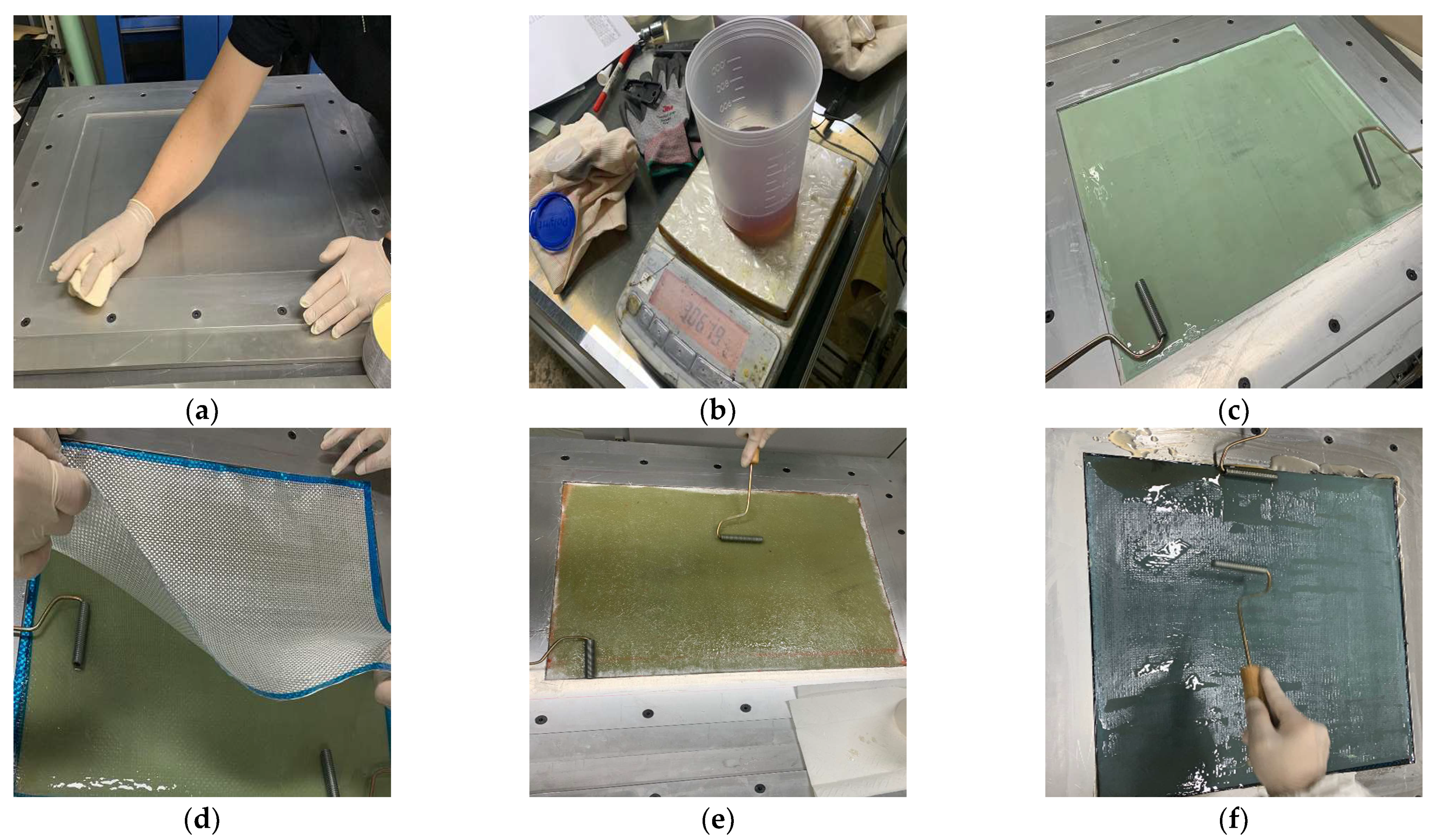
3.1. Hand Lay-Up Method
- (1)
- Prepare a 500 × 1000 mm2 bi-directional carbon plain weave fabric (0°/90°, 200 g/m2). Carbon fiber fabrics were purchased from Toray company (Tokyo, Japan).
- (2)
- Apply it to the mold surface using a release agent before lamination. In this experiment, a liquid release agent was used for uniform application.
- (3)
- Stir the epoxy resin. For the resin used in this experiment, mix KINETIX R118 infusion resin and H120 infusion hardener in a ratio of 100:25 and mix for 90 s.
- (4)
- After placing peel ply on the mold, impregnate it with resin. Peel ply facilitates the escape of the specimen and smooths the surface of the specimen. It also serves to prevent the inflow of external air bubbles.
- (5)
- On the peel ply, impregnate one piece of textile fabric. A brush or roller is used as an impregnation tool.
- (6)
- Finally, impregnate the peel ply and cover it with a release film to prevent the inflow of external air bubbles prior to addition; finish the preparation of the specimen.
- (7)
- After curing for 24 h, remove the peel ply to degrease the laminated specimen, then cut it according to the desired grid size to manufacture the FRP grid.
- (8)
- Hand lay-up specimens require the skill of the operator to remove air bubbles and uniformly impregnate the resin when impregnating the textile fabric.
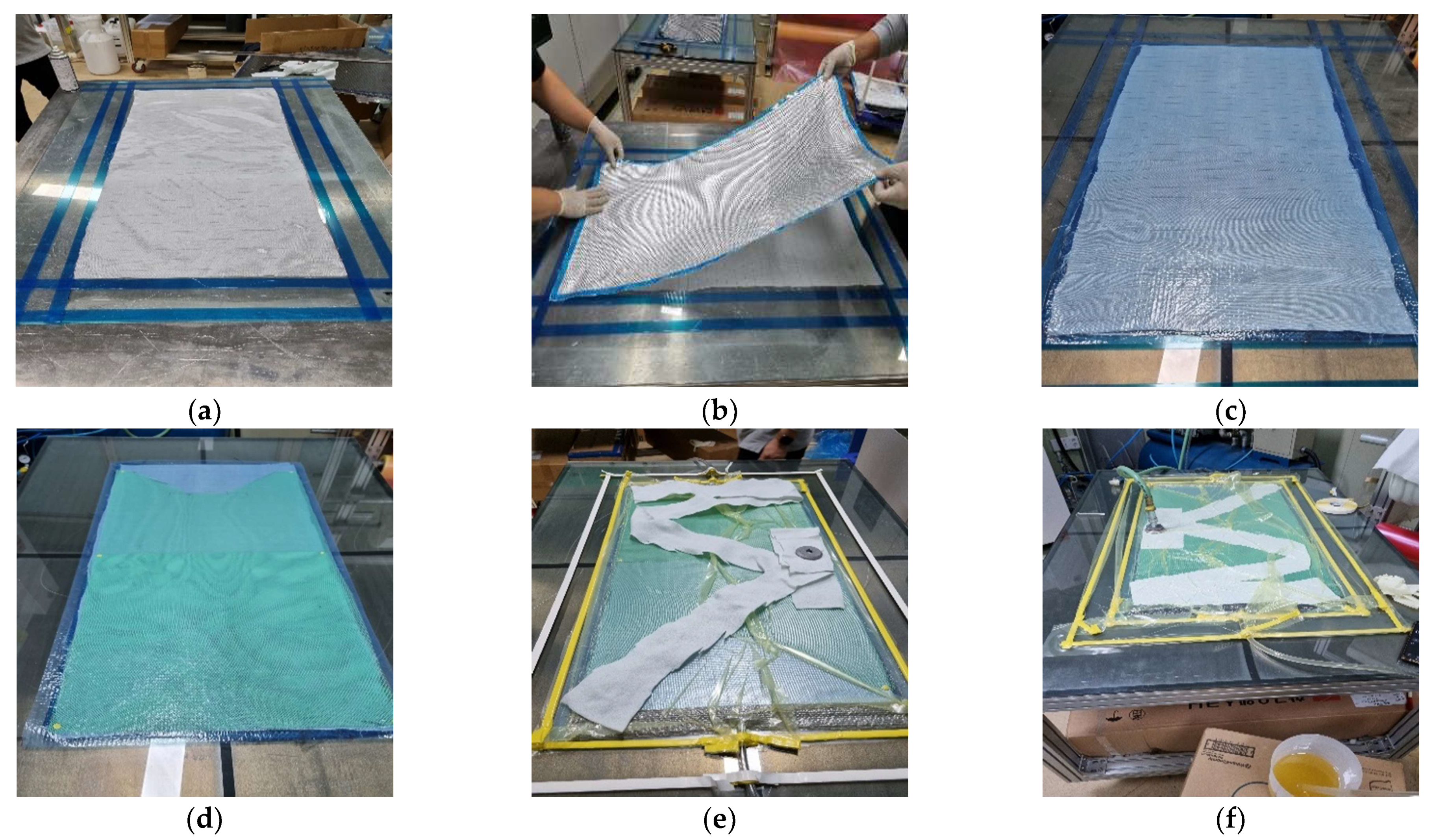
3.2. Resin Infusion Method
- (1)
- Prepare a 500 × 1000 mm2 bi-directional carbon plain weave fabric (0°/90°, 200 g/m2). Carbon fiber fabrics were purchased from Toray company (Japan).
- (2)
- Apply to the mold surface using a release agent before lamination. In this experiment, a liquid release agent was used for uniform application.
- (3)
- Stir the epoxy resin. In this experiment, Resoltech resin 1050 and Resoltech hardener 1056 were mixed in a ratio of 100:35 and mixed for 90 s.
- (4)
- After spraying the spray adhesive onto the mold, apply a peel ply.
- (5)
- Lay each fiber fabric on the peel ply one by one using spray adhesive.
- (6)
- On the laminated textile fabric, laminate in the order of peel ply, release film, and mesh. The mesh facilitates resin fluidity in the longitudinal direction of the product such that the resin can be filled. The resin is cut 10–20% shorter in the longitudinal direction to form a break line.
- (7)
- Install omega flow and resin ports on both sides of the fabric in the longitudinal direction. Omega flow plays a role in smoothly reaching the desired length of the resin. The resin port is inserted by cutting the omega flow and is fixed with sealant to prevent leakage.
- (8)
- Lay the breather on the mesh, fix the bagging film around the fabric using sealant, and hold the vacuum twice. The breather plays the role of evenly distributing the vacuum pressure, preventing vacuum bag leakage, and holding the vacuum twice for uniformity of specimen thickness.
- (9)
- Inject the resin through the resin port and proceed until it finally arrives in the longitudinal direction of the product. Check the temperature of the resin during injection. As the temperature increases, the viscosity of the resin decreases; thus, when the temperature rises above a certain temperature, new resin is injected.
- (10)
- After resin injection is completed, after curing for 24 h, remove the peel ply to strip the laminated specimen, then cut it to the desired grid size to manufacture the FRP grid.
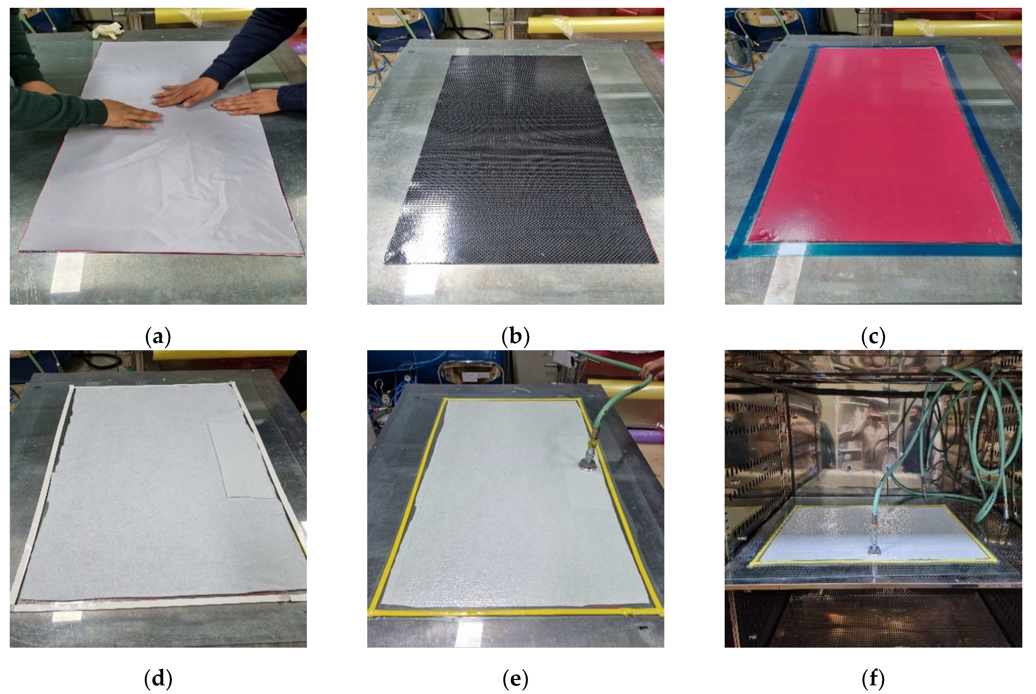
3.3. Prepreg OVB Method
- (1)
- After attaching the peel ply through the air adhesive, laminate an adhesive film and one sheet of prepreg.
- (2)
- After attaching the first sheet of prepreg to the mold, laminate the release film and vacuum film.
- (3)
- After applying the breather, hold the vacuum injector and perform vacuum compaction at 50 degrees for 30 min.
- (4)
- After compaction, remove the release film, vacuum film, and breather, and then stack 2~3 ply of prepreg according to thickness and repeat steps 2 and 3. For complete adhesion between ply and removal of interstitial pores, do not laminate at once.
- (5)
- After lamination is complete, perform compaction at 50 °C for 30 min, hardening at 120 °C for 2 h, then strip and cut to the desired grid size to manufacture the FRP grid.
4. Results and Discussion
4.1. Load-Extension of CFRP/GFRP Grid
4.2. Fracture Mode of the Composites
4.3. Partial Tensile Strain of FRP Grid
4.4. Tensile Strain Distribution of FRP Grid
4.5. Finite Element Analysis of CFRP/GFRP Grid
5. Conclusions
- (1)
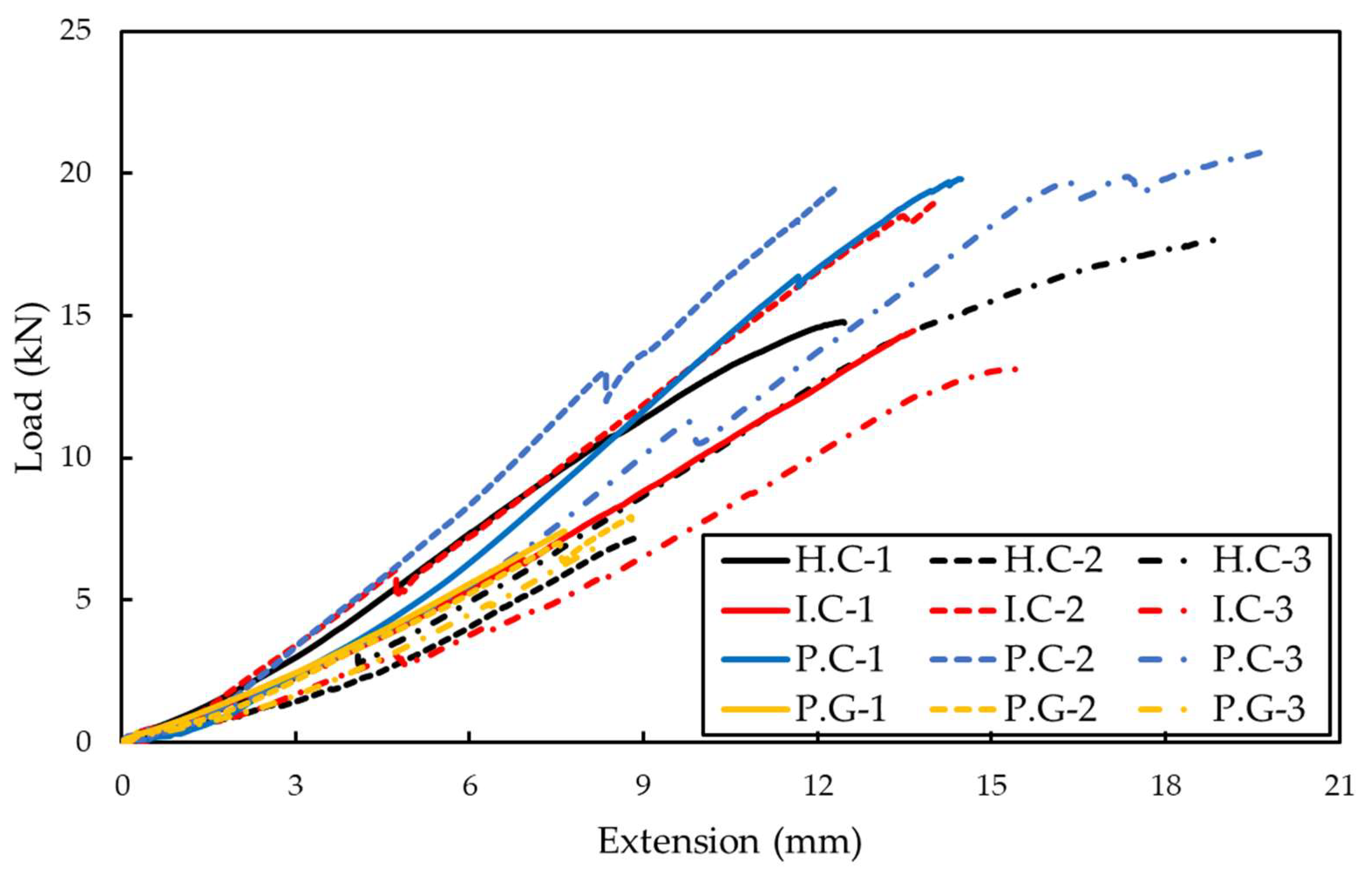
- The load extension results of the pull-out test, including the maximum tensile strain, stress, and load, were evaluated. The tensile behavior of the FRP grid was affected by the difference in fiber impregnation rate and inter-sheet adhesion, according to the processing process. The P.C specimen manufactured by the prepreg OVB method showed 15.68% and 8.14% higher displacements and 56.38% and 7.42% higher maximum loads compared to the H.C and I.C specimens, respectively.
- (2)
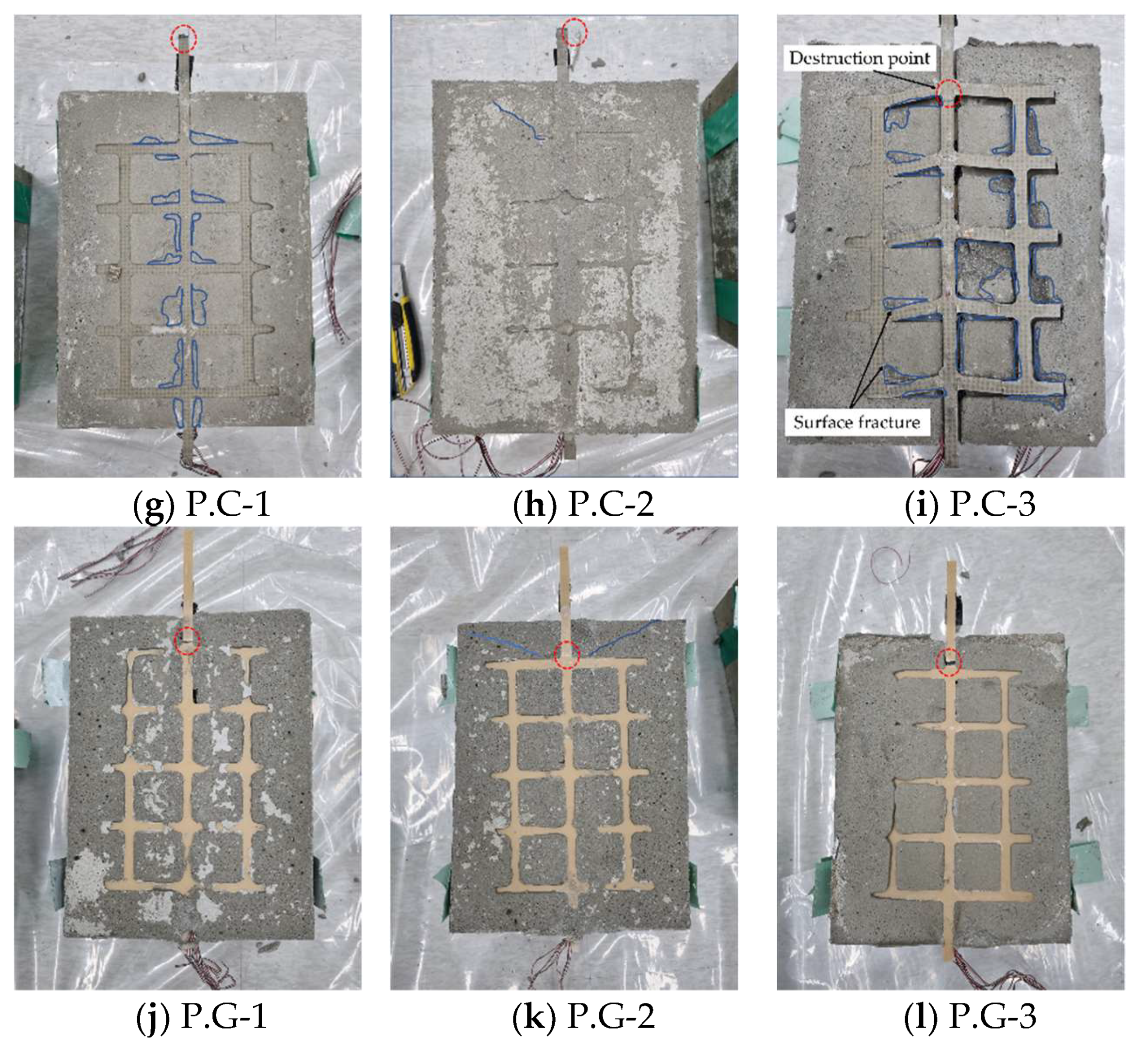
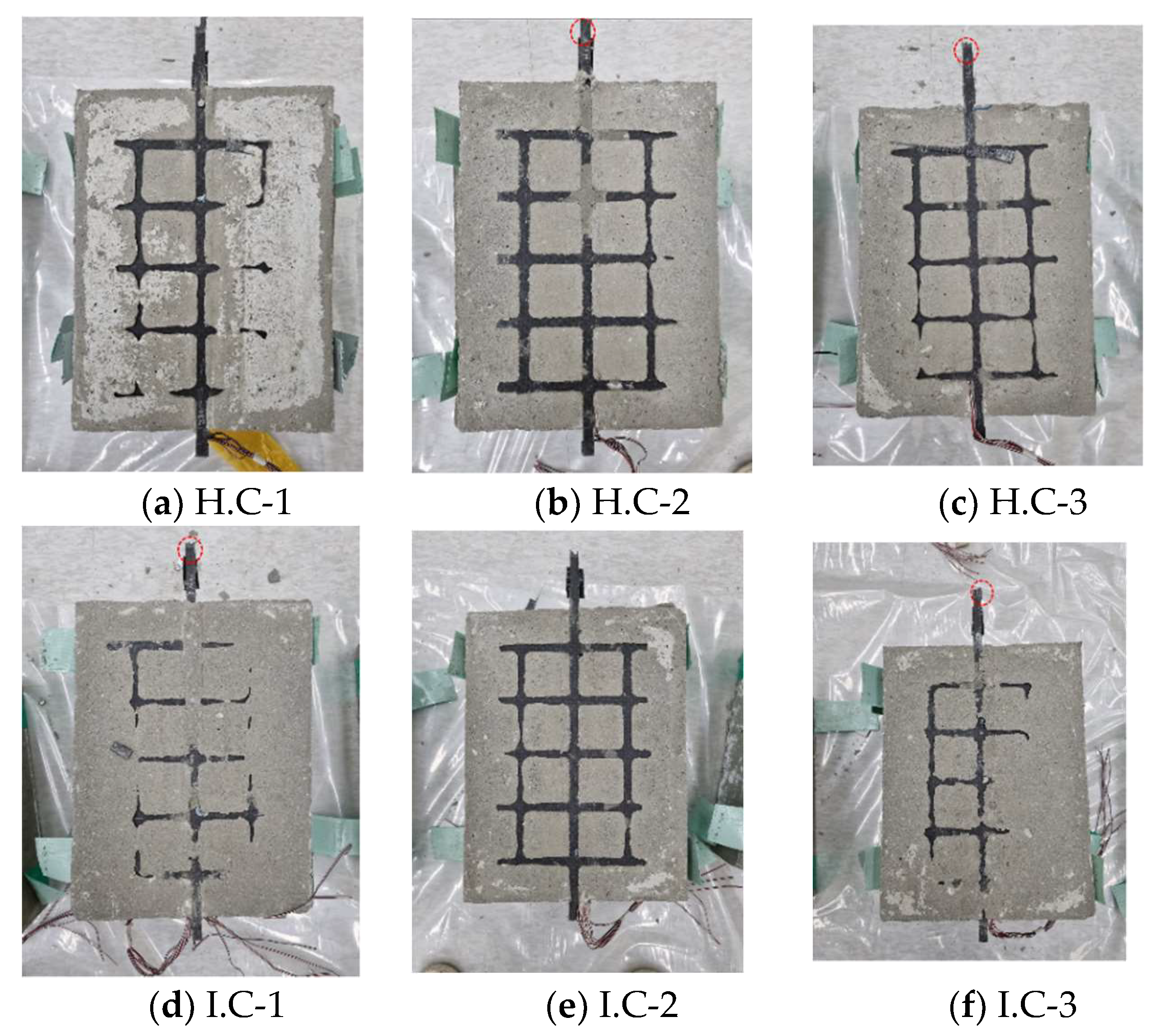
- The fracture shapes of the composites after the pull-out were analyzed. The fractured part of the FRP grid embedded in composites varied depending on the relationship between the tensile strength of the grid and the compressive strength of the mortar resisting the compressive stress of the horizontal grid.
- (3)
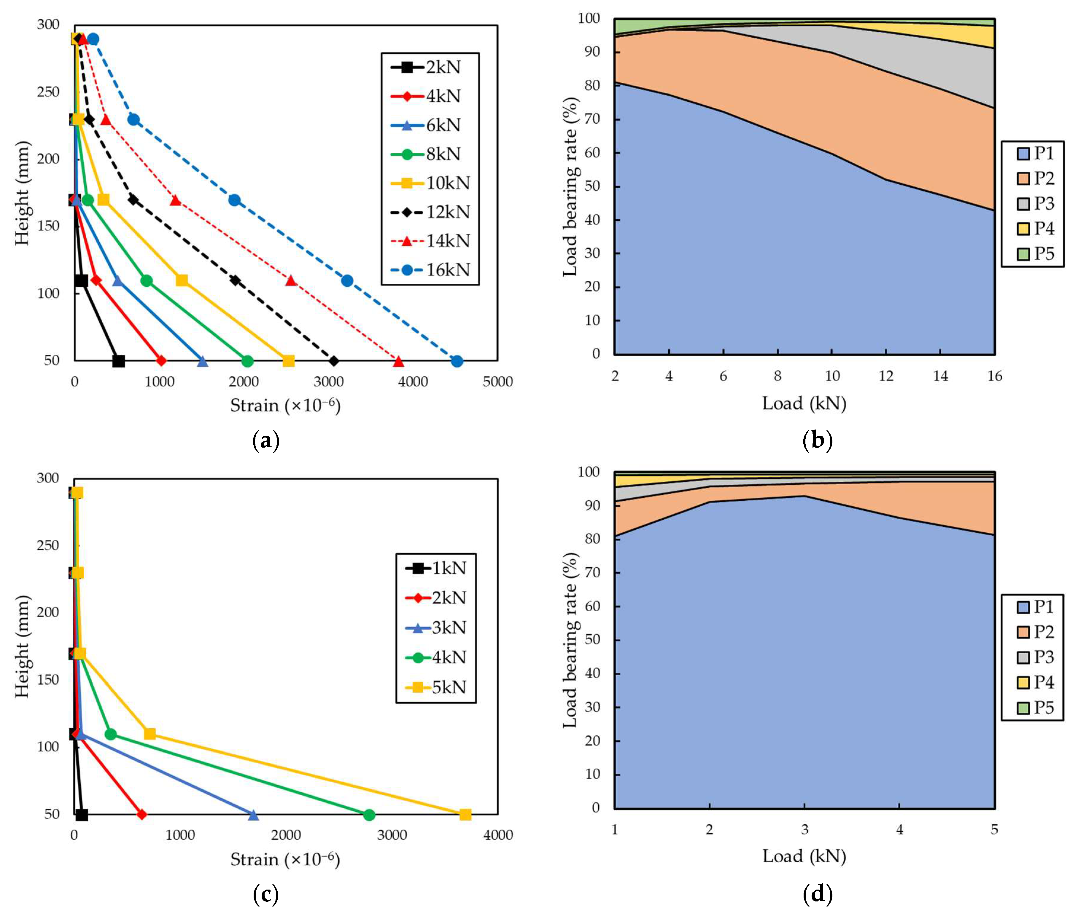
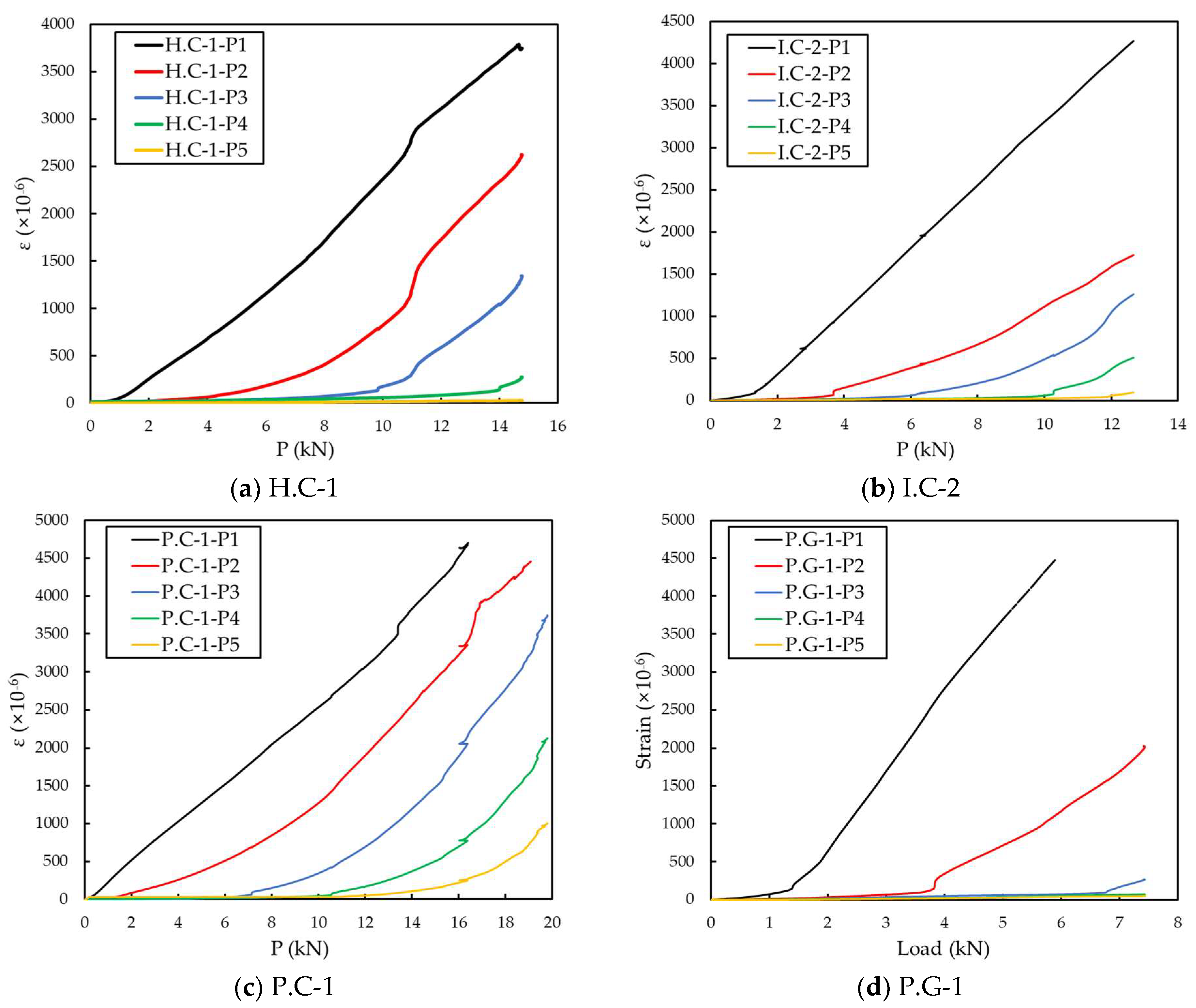
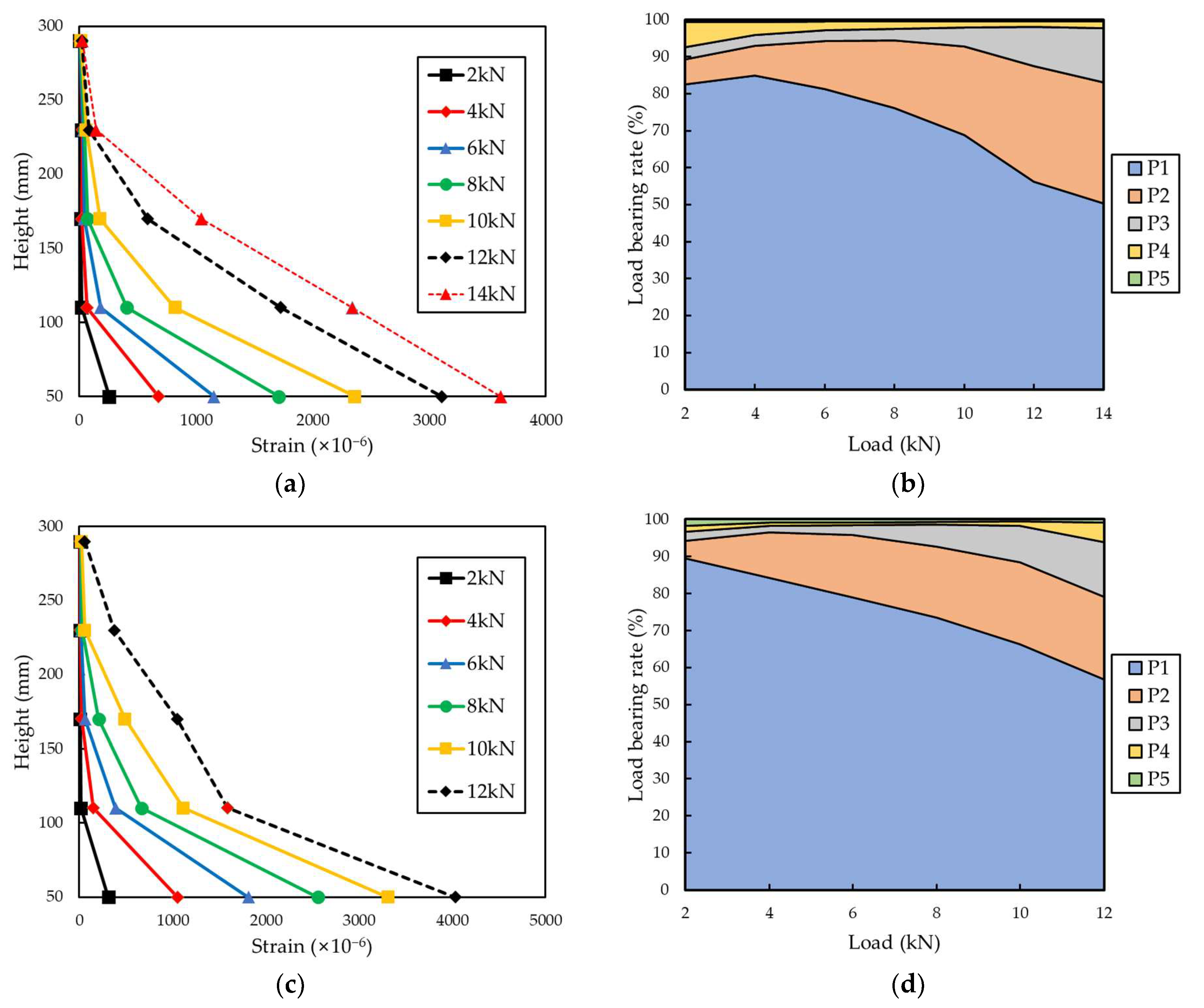
- The partial tensile strain of each grid point was investigated. The partial tensile strain of the FRP grid increased with the distance from the load-bearing part, the load at which the deformation began. At a low-tensile-load section, the deformation mainly occurred at the upper part of the FRP grid. As the tensile load increased, the deformation of the FRP grid was transmitted to the lower part of the FRP grid. The FRP grid embedded in composites did not undergo constant deformation but had different deformations in parts.
- (4)
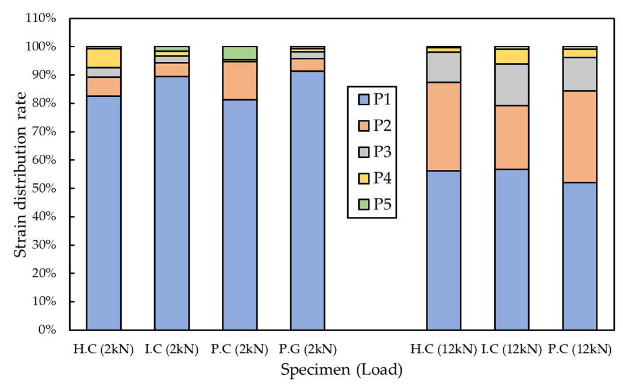
- The load-bearing rate of each grid point was evaluated. The load-bearing rate of each grid point was proportional to the height from the load-bearing part when reaching the maximum tensile load. The magnitude of the applied load had a dominant influence on the strain distribution of the FRP grid embedded in composites.
- (5)
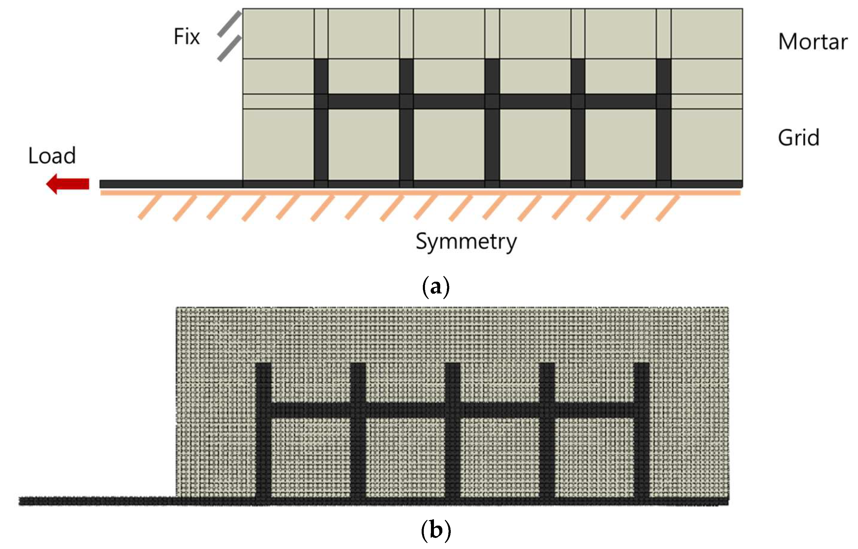
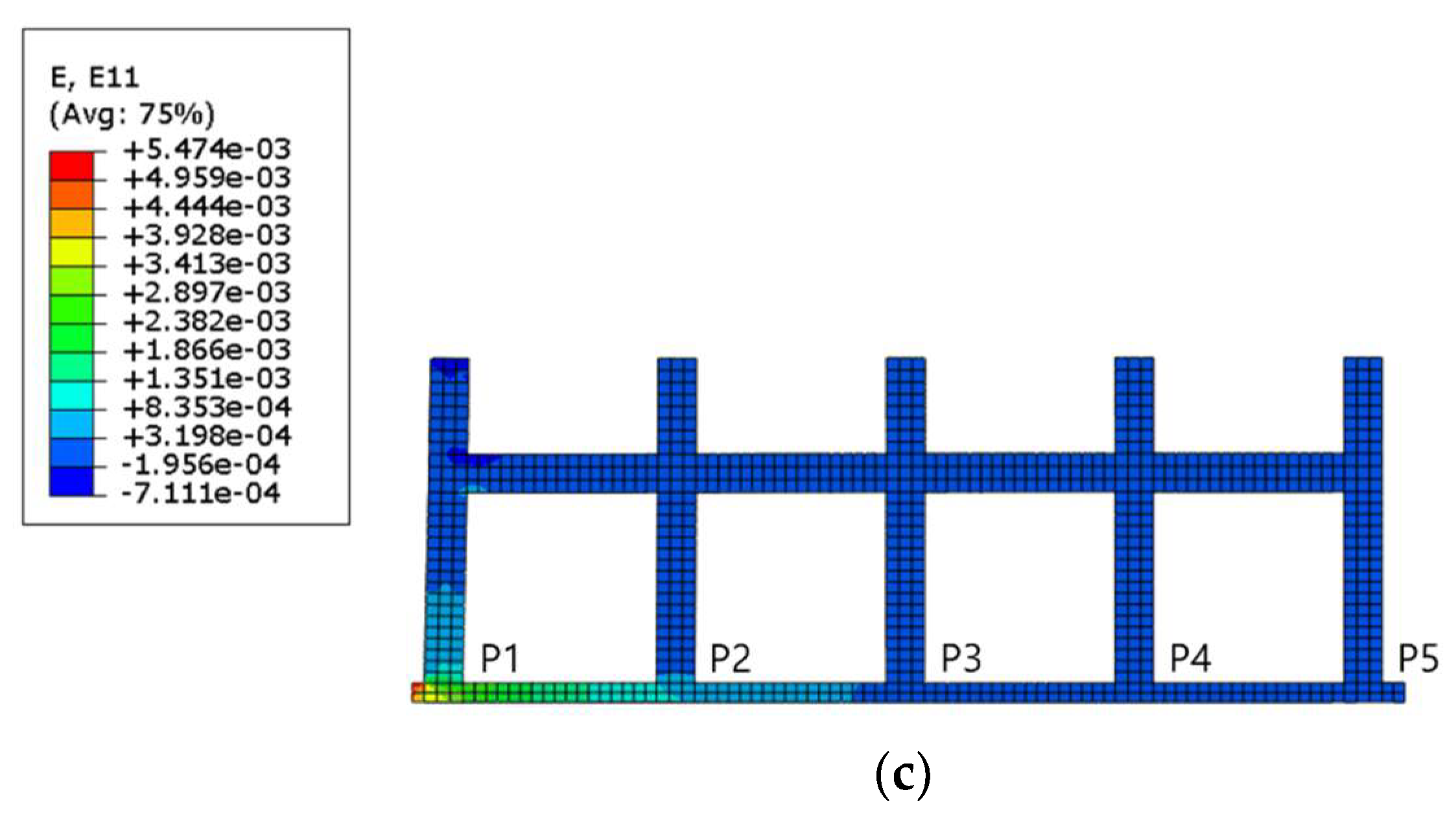
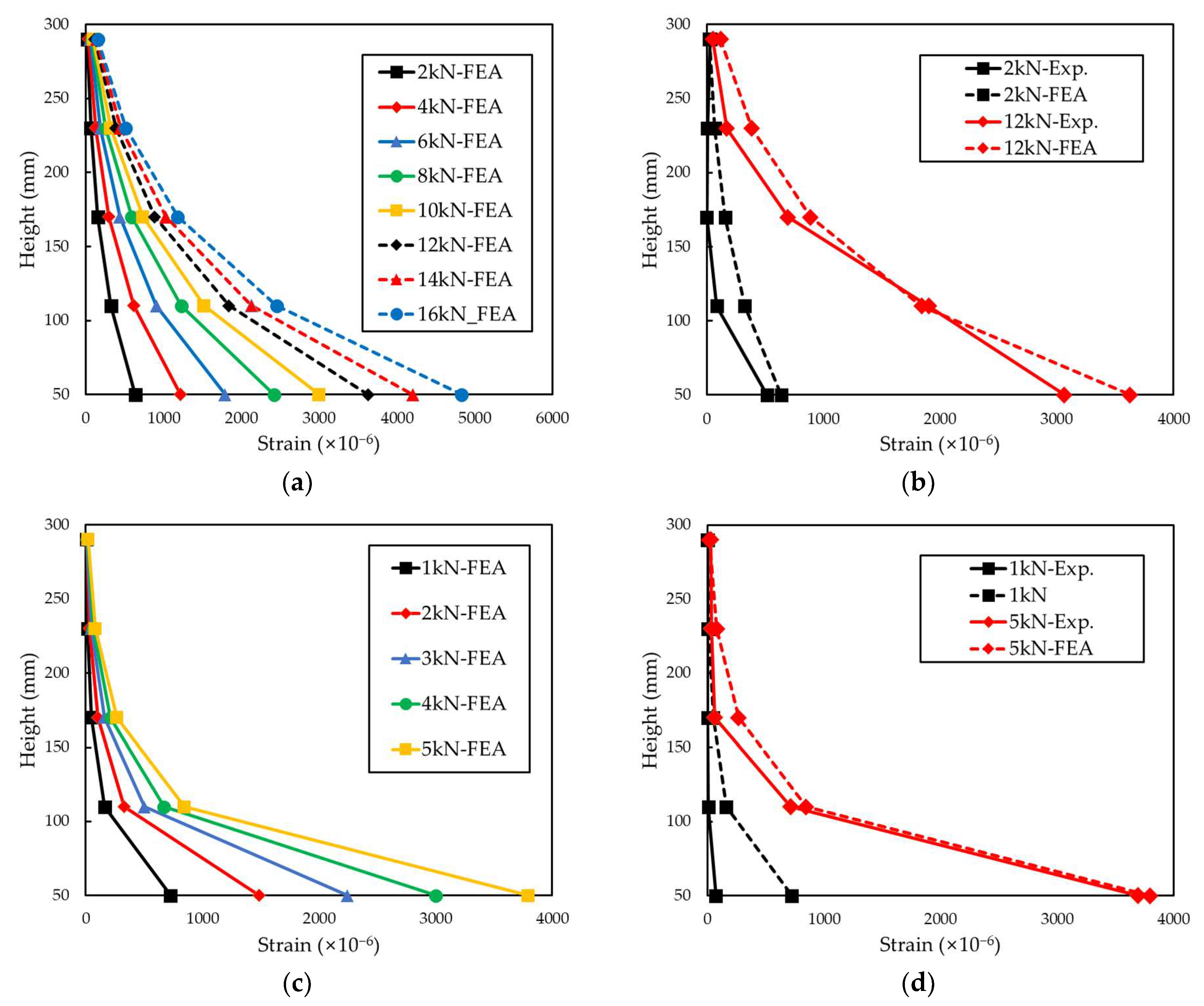
- Finite element analysis of FRP grid were conducted by using ABAQUS commercial tools. As a result of the finite element analysis, the strain values of the two grid materials were similar to the experimental results. Analysis results indicated that the tensile stress is concentrated in the load-bearing part. P1 grid point showed the highest load-bearing rate, and the rate decreased as the distance from the load-bearing part increased at FEA results.
Author Contributions
Funding
Institutional Review Board Statement
Informed Consent Statement
Data Availability Statement
Conflicts of Interest
References
- James, A.; Bazarchi, E.; Chiniforush, A.A.; Panjebashi Aghdam, P.; Hosseini, M.R.; Akbarnezhad, A.; Martek, I.; Ghodoosi, F. Rebar Corrosion Detection, Protection, and Rehabilitation of Reinforced Concrete Structures in Coastal Environments: A Review. Constr. Build. Mater. 2019, 224, 1026–1039. [Google Scholar] [CrossRef] [Scilit]
- Aydin, F. Experimental Investigation of Thermal Expansion and Concrete Strength Effects on FRP Bars Behavior Embedded in Concrete. Constr. Build. Mater. 2018, 163, 1–8. [Google Scholar] [CrossRef] [Scilit]
- Khan, I.; François, R.; Castel, A. Prediction of Reinforcement Corrosion Using Corrosion Induced Cracks Width in Corroded Reinforced Concrete Beams. Cem. Concr. Res. 2014, 56, 84–96. [Google Scholar] [CrossRef] [Scilit]
- Oh, B.H.; Kim, K.H.; Jang, B.S. Corrosion Amount to Cause Cracking of Reinforced Concrete Structures. ACI Mater. J. 2009, 106, 333–339. [Google Scholar]
- Jin, L.; Zhang, R.; Du, X.; Li, Y. Investigation on the Cracking Behavior of Concrete Cover Induced by Corner Located Rebar Corrosion. Eng. Fail. Anal. 2015, 52, 129–143. [Google Scholar] [CrossRef] [Scilit]
- Zhang, B.; Masmoudi, R.; Benmokrane, B. Behaviour of One-Way Concrete Slabs Reinforced with CFRP Grid Reinforcements. Constr. Build. Mater. 2004, 18, 625–635. [Google Scholar] [CrossRef] [Scilit]
- Gadve, S.; Mukherjee, A.; Malhotra, S.N. Corrosion of Steel Reinforcements Embedded in FRP Wrapped Concrete. Constr. Build. Mater. 2009, 23, 153–161. [Google Scholar] [CrossRef] [Scilit]
- Meng, W.; Khayat, K.H.; Bao, Y. Flexural Behaviors of Fiber-Reinforced Polymer Fabric Reinforced Ultra-High-Performance Concrete Panels. Cem. Concr. Compos. 2018, 93, 43–53. [Google Scholar] [CrossRef] [Scilit]
- Thermal Stress and Deformation Analyses in Fiber Reinforced Polymer Composites Undergoing Heat Conduction and Mechanical Loading—ScienceDirect. Available online: https://www.sciencedirect.com/science/article/pii/S0263822313006181?casa_token=jlR7tEwXPDMAAAAA:oHP0Zn5-VFVM-AEzbCzLifFsBDZt5CU6ka4UyMqMySo5uATYK21tN39C267px1C-PYLdJv0DTwxo (accessed on 30 November 2021).
- Jesthi, D.K.; Nayak, R.K. Evaluation of Mechanical Properties and Morphology of Seawater Aged Carbon and Glass Fiber Reinforced Polymer Hybrid Composites. Compos. Part B Eng. 2019, 174, 106980. [Google Scholar] [CrossRef] [Scilit]
- Itam, Z.; Ishak, Z.A.M.; Yusof, Z.M.; Salwi, N.; Zainoodin, M. Effect on the Temperature Behavior of Glass Fiber Reinforced Polymer (GFRP) in Various Application—A Review. AIP Conf. Proc. 2018, 2031, 020026. Available online: https://aip.scitation.org/doi/abs/10.1063/1.5066982 (accessed on 30 December 2021).
- Vara Prasad, V.; Talupula, S. A Review on Reinforcement of Basalt and Aramid (Kevlar 129) Fibers. Mater. Today Proc. 2018, 5, 5993–5998. [Google Scholar] [CrossRef] [Scilit]
- Sathishkumar, T.P.; Satheeshkumar, S.; Naveen, J. Glass Fiber-Reinforced Polymer Composites—A Review. J. Reinf. Plast. Compos. 2014, 3, 1258–1275. Available online: https://journals.sagepub.com/doi/full/10.1177/0731684414530790?casa_token=oAQBgDMUvEYAAAAA%3AncqFZkhVists8ws6N1piffXDpAMhU9APGSWpPsuPCZAjKf9nTf7S4619Jtax2E2r3Zp4BNFYnJaNHz4 (accessed on 30 November 2021). [CrossRef] [Scilit]
- Liu, Y.; Zwingmann, B.; Schlaich, M. Carbon Fiber Reinforced Polymer for Cable Structures—A Review. Polymers 2015, 7, 2078–2099. [Google Scholar] [CrossRef] [Scilit]
- Wittman, C.; Shook, G.D. Hand Lay-Up Techniques. In Handbook of Composites; Lubin, G., Ed.; Springer: Boston, MA, USA, 1982; pp. 321–367. ISBN 978-1-4615-7139-1. [Google Scholar]
- Ha, S.K.; Na, S.; Lee, H.K. Bond Characteristics of Sprayed FRP Composites Bonded to Concrete Substrate Considering Various Concrete Surface Conditions. Compos. Struct. 2013, 100, 270–279. [Google Scholar] [CrossRef] [Scilit]
- Kleineberg, M.; Wenner, U.; Hanke, M. Cost Effective CFRP-Fuselage Manufacturing with Liquid Resin Infusion (LRI)–Technologies. In Workshop at German Aerospace Centre (DLR) on Final Project of Black Fuselage; Braunschweig, Germany, 2002; pp. 147–150. Available online: https://citeseerx.ist.psu.edu/viewdoc/download?doi=10.1.1.610.729&rep=rep1&type=pdf (accessed on 21 December 2021).
- Tiwari, G.N.; Lawrence, S.A. Experimental Evaluation of Solar Distiller Units with Frp Lining Under Png Climatic Conditions. Int. J. Sol. Energy 1991, 9, 241–248. [Google Scholar] [CrossRef] [Scilit]
- Resin Infusion/Liquid Composite Moulding (LCM) of Advanced Fibre-Reinforced Polymer (FRP)—ScienceDirect. Available online: https://www.sciencedirect.com/science/article/pii/B9780857094186500077 (accessed on 21 December 2021).
- Abdelal, N.R.; Irshidat, M.R. Utilizing Vacuum Bagging Process to Enhance Bond Strength between FRP Sheets and Concrete. Struct. Eng. Mech. 2019, 72, 305–312. [Google Scholar] [CrossRef]
- Ge, W.; Ashour, A.F.; Cao, D.; Lu, W.; Gao, P.; Yu, J.; Ji, X.; Cai, C. Experimental Study on Flexural Behavior of ECC-Concrete Composite Beams Reinforced with FRP Bars. Compos. Struct. 2019, 208, 454–465. [Google Scholar] [CrossRef] [Scilit]
- Zhang, P.; Su, Y.; Liu, Y.; Gao, D.; Sheikh, S.A. Flexural Behavior of GFRP Reinforced Concrete Beams with CFRP Grid-Reinforced ECC Stay-in-Place Formworks. Compos. Struct. 2021, 277, 114653. [Google Scholar] [CrossRef] [Scilit]
- Zhu, Z.-F.; Wang, W.-W.; Hui, Y.-X.; Hu, S.-W.; Men, G.-Y.; Tian, J.; Huang, H. Mechanical Behavior of Concrete Columns Confined with CFRP Grid-Reinforced Engineered Cementitious Composites. J. Compos. Constr. 2022, 26, 04021060. [Google Scholar] [CrossRef] [Scilit]
- Guo, R.; Pan, Y.; Cai, L.; Hino, S. Bonding Behavior of CFRP Grid-Concrete with PCM Shotcrete. Eng. Struct. 2018, 168, 333–345. [Google Scholar] [CrossRef] [Scilit]
- Wang, B.; Uji, K.; Wu, T.; Dai, H.; Yan, D.; Guo, R. Experimental Investigation of Stress Transfer and Failure Mechanism between Existing Concrete and CFRP Grid-Sprayed PCM. Constr. Build. Mater. 2019, 215, 43–58. [Google Scholar] [CrossRef] [Scilit]
- Hong, K.; Shin, J.; Han, S.; Seo, D.; Ahn, K. Mechanical Properties of Very Rapid Hardening Polymer Mortar for Concrete Repair. J. Korean GEO-Environ. Soc. 2014, 15, 31–37. [Google Scholar] [CrossRef] [Scilit]
- Choi, H.-K.; Nam, K.-W.; Ahn, S.-H. Strength Characteristics of FRP Composite Materials for Ship Structure. J. Ocean. Eng. Technol. 2013, 27, 45–54. [Google Scholar] [CrossRef] [Scilit]






| No. | Sheet | Ply | Nominal Weight (gsm) | Density (g/mm3 × 10−3) | Impregnation Rate of Fiber (wt. %) | ||
|---|---|---|---|---|---|---|---|
| Fiber | Resin | Fiber | Resin | ||||
| 1 | Carbon fabric | 6 | 420 | 344 | 1.78 | 1.20 | 55 |
| 2 | Carbon fabric | 6 | 420 | 180 | 1.78 | 1.20 | 70 |
| 3 | Carbon prepreg | 6 | 400 | 216 | 1.78 | 1.20 | 57.4 |
| Adhesive film | 2 | - | 244 | - | 1.20 | ||
| 4 | Glass prepreg | 10 | 323 | 174 | 2.54 | 1.20 | 59.2 |
| Adhesive film | 2 | - | 244 | - | 1.20 | ||
| Specimen Code | Sheet | Method | Thickness (mm) | Width (mm) |
|---|---|---|---|---|
| H.C | Carbon fabric | Hand lay-up | 3.1 | 10 |
| I.C | Carbon fabric | Resin infusion | 2.6 | |
| P.C | Carbon prepreg | OVB | 2.8 | |
| P.G | Glass prepreg | OVB | 3.1 |
| W/B | Cement | Sand | Gravel | Water | Admixture |
|---|---|---|---|---|---|
| 0.5 | 457 | 686 | 1086 | 229 | 23 |
| Specimen | Ultimate Tensile Strain (%) | Maximum Load (kN) | Ultimate Tensile Stress (MPa) |
|---|---|---|---|
| H.C | 3.84 | 13.23 | 402.04 |
| I.C | 4.10 | 15.54 | 585.30 |
| P.C | 4.44 | 20.02 | 628.73 |
| P.G | 2.35 | 7.43 | 224.82 |
Publisher’s Note: MDPI stays neutral with regard to jurisdictional claims in published maps and institutional affiliations. |
© 2022 by the authors. Licensee MDPI, Basel, Switzerland. This article is an open access article distributed under the terms and conditions of the Creative Commons Attribution (CC BY) license (https://creativecommons.org/licenses/by/4.0/).
Share and Cite
Kim, J.S.; Kim, S.J.; Min, K.J.; Choi, J.C.; Eun, H.S.; Song, B.K. A Study on Tensile Behavior According to the Design Method for the CFRP/GFRP Grid for Reinforced Concrete. Materials 2022, 15, 357. https://doi.org/10.3390/ma15010357
Kim JS, Kim SJ, Min KJ, Choi JC, Eun HS, Song BK. A Study on Tensile Behavior According to the Design Method for the CFRP/GFRP Grid for Reinforced Concrete. Materials. 2022; 15(1):357. https://doi.org/10.3390/ma15010357
Chicago/Turabian StyleKim, Jin Sung, Seong Jong Kim, Kyoung Jae Min, Jung Chul Choi, Hwa Seong Eun, and Bhum Keun Song. 2022. "A Study on Tensile Behavior According to the Design Method for the CFRP/GFRP Grid for Reinforced Concrete" Materials 15, no. 1: 357. https://doi.org/10.3390/ma15010357
APA StyleKim, J. S., Kim, S. J., Min, K. J., Choi, J. C., Eun, H. S., & Song, B. K. (2022). A Study on Tensile Behavior According to the Design Method for the CFRP/GFRP Grid for Reinforced Concrete. Materials, 15(1), 357. https://doi.org/10.3390/ma15010357