
Powder Interlayer Bonding of Nickel-Based Superalloys with Dissimilar Chemistries


Abstract
1. Introduction
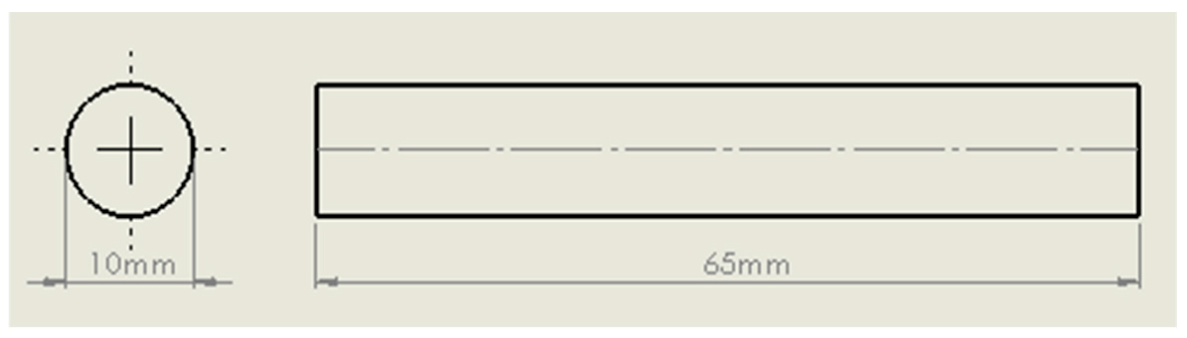
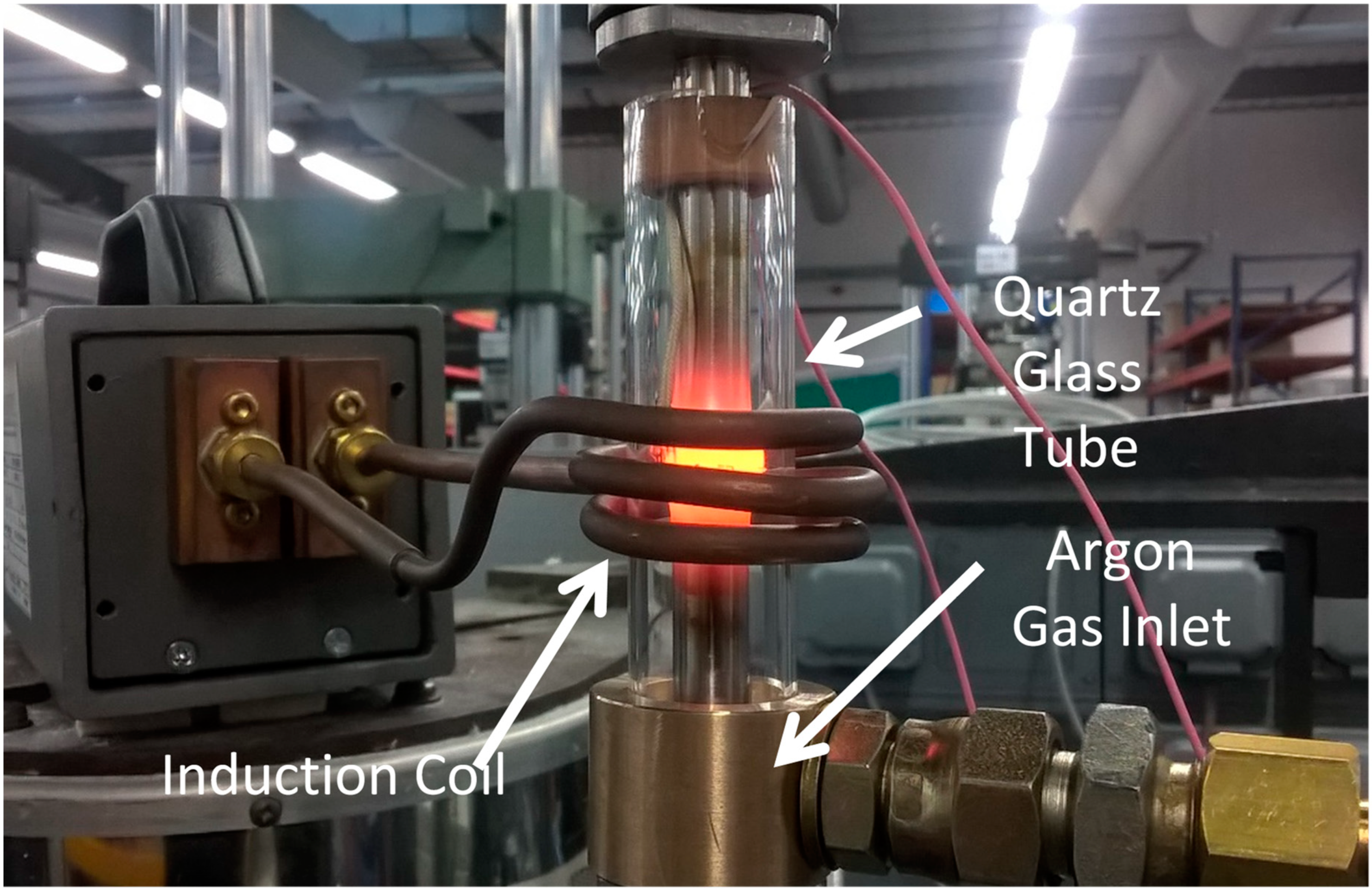
2. Materials and Methods
3. Results and Discussion
3.1. Base Materials
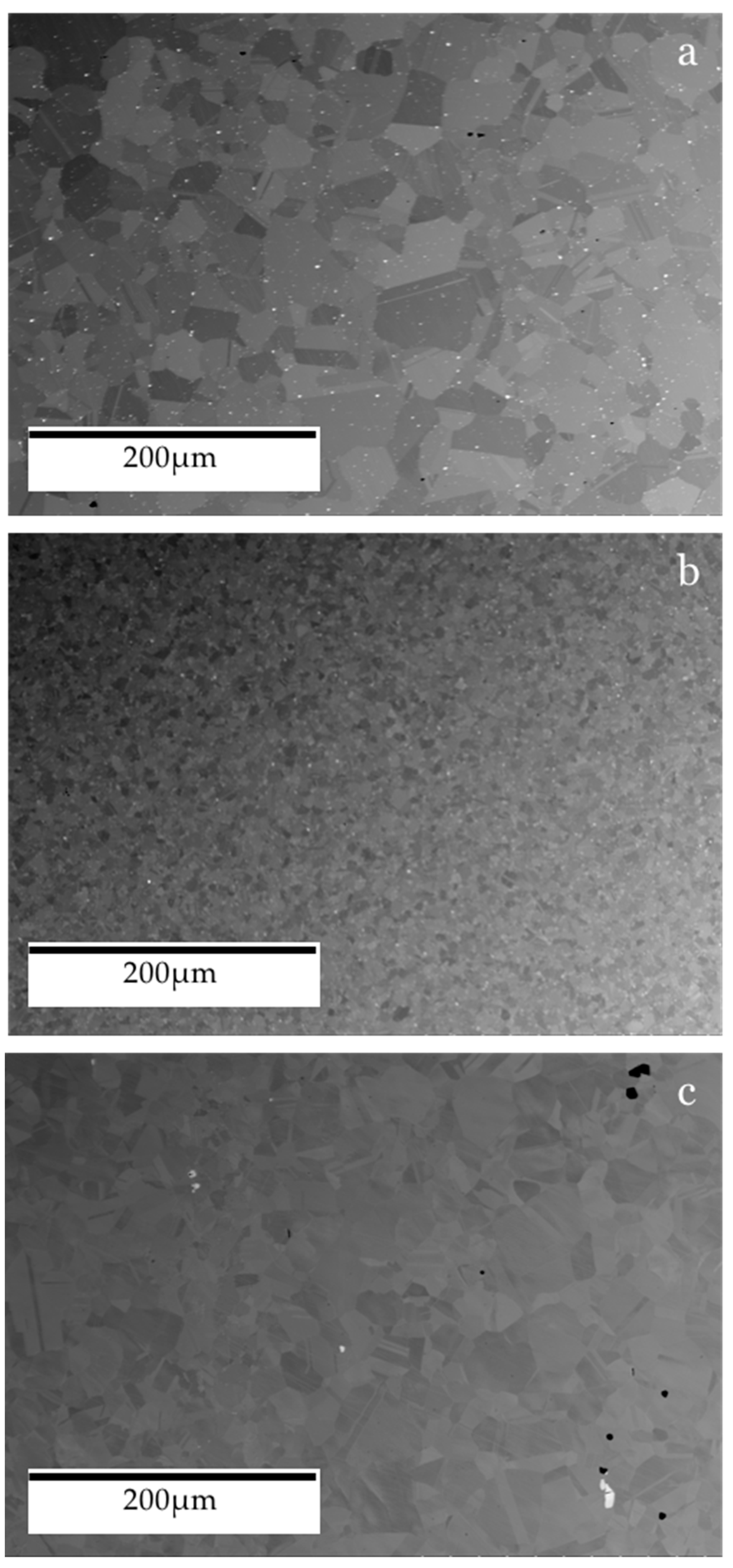
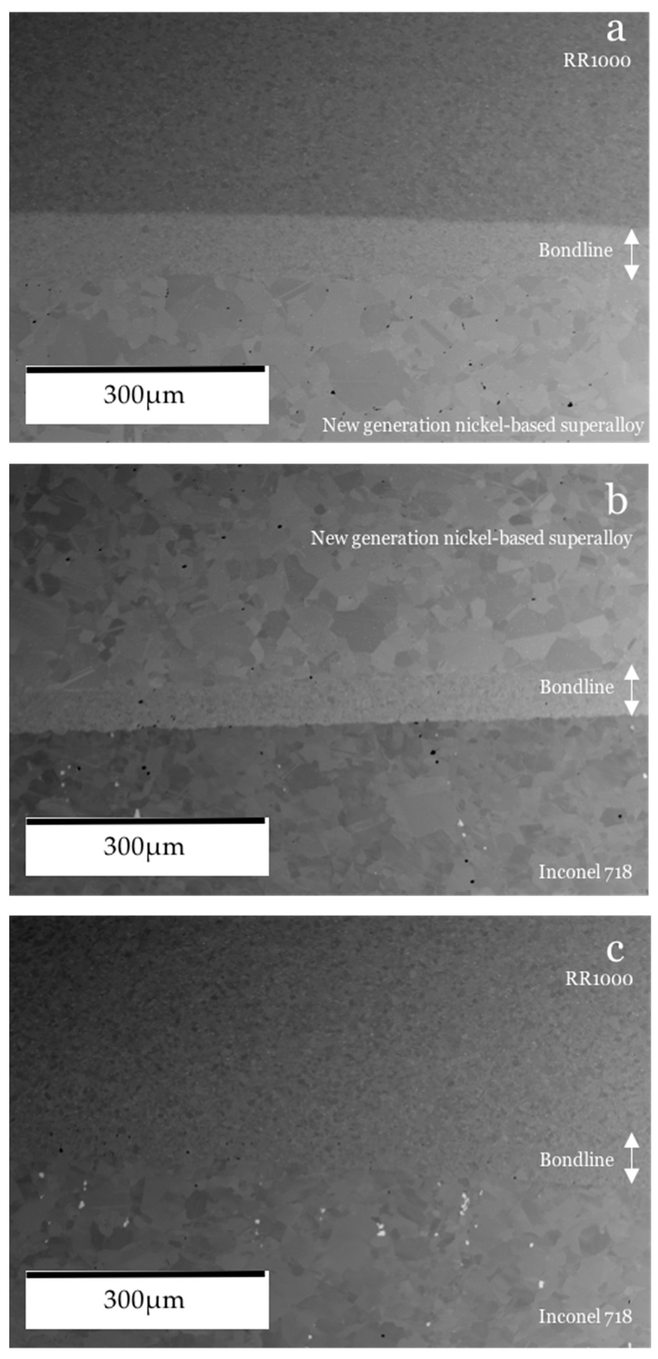
3.2. Grain Size
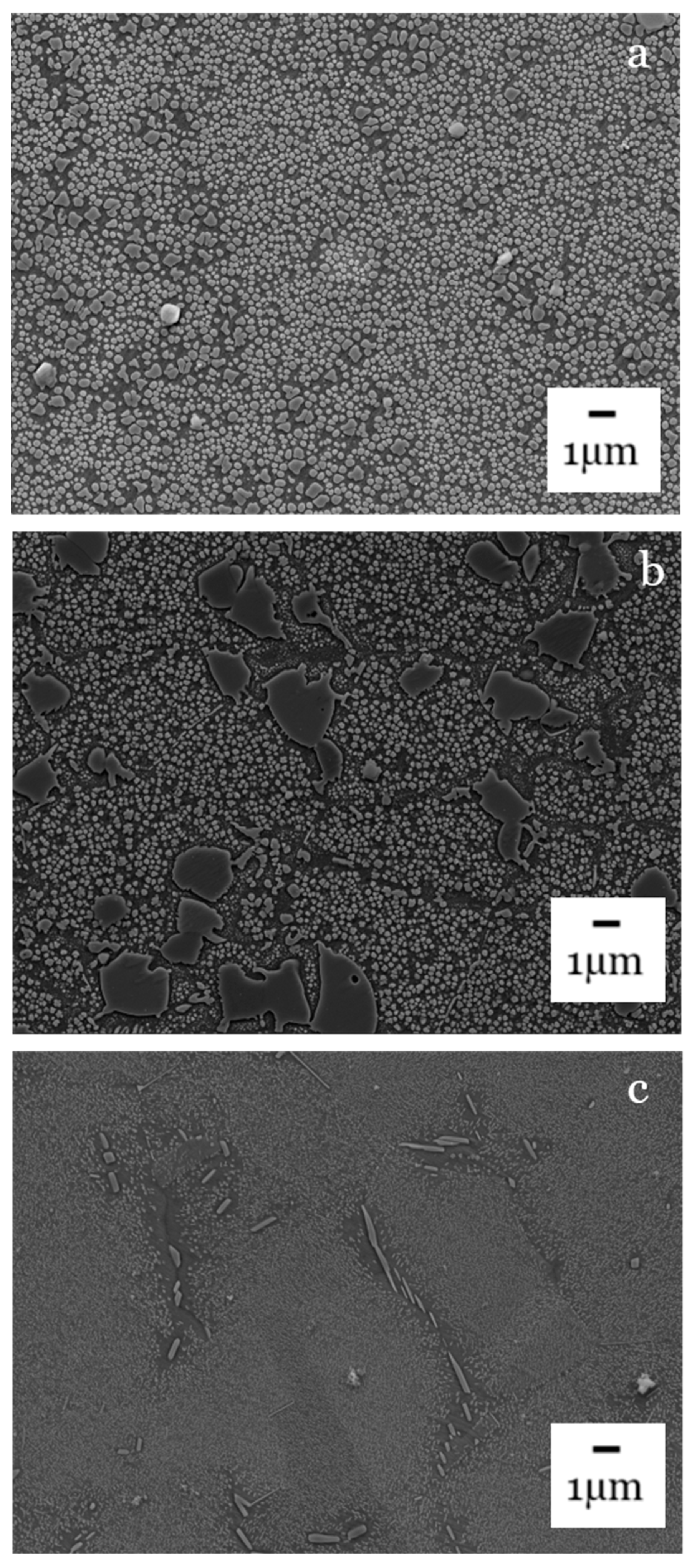
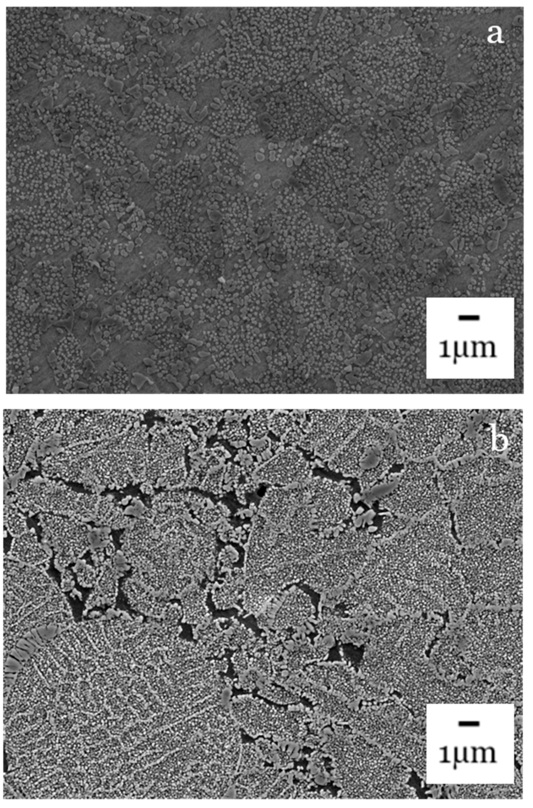
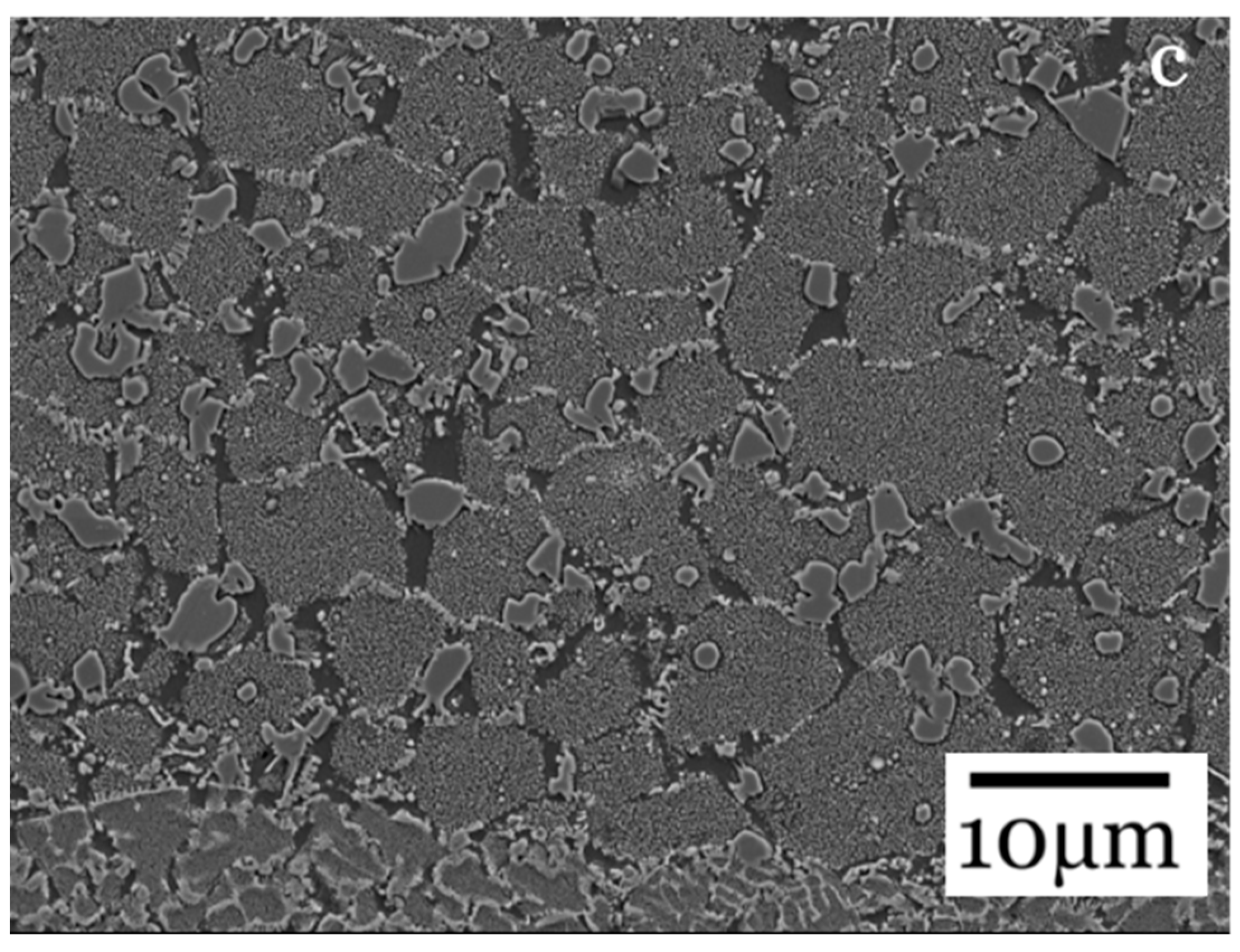
3.3. γ′/γ″ Morphology
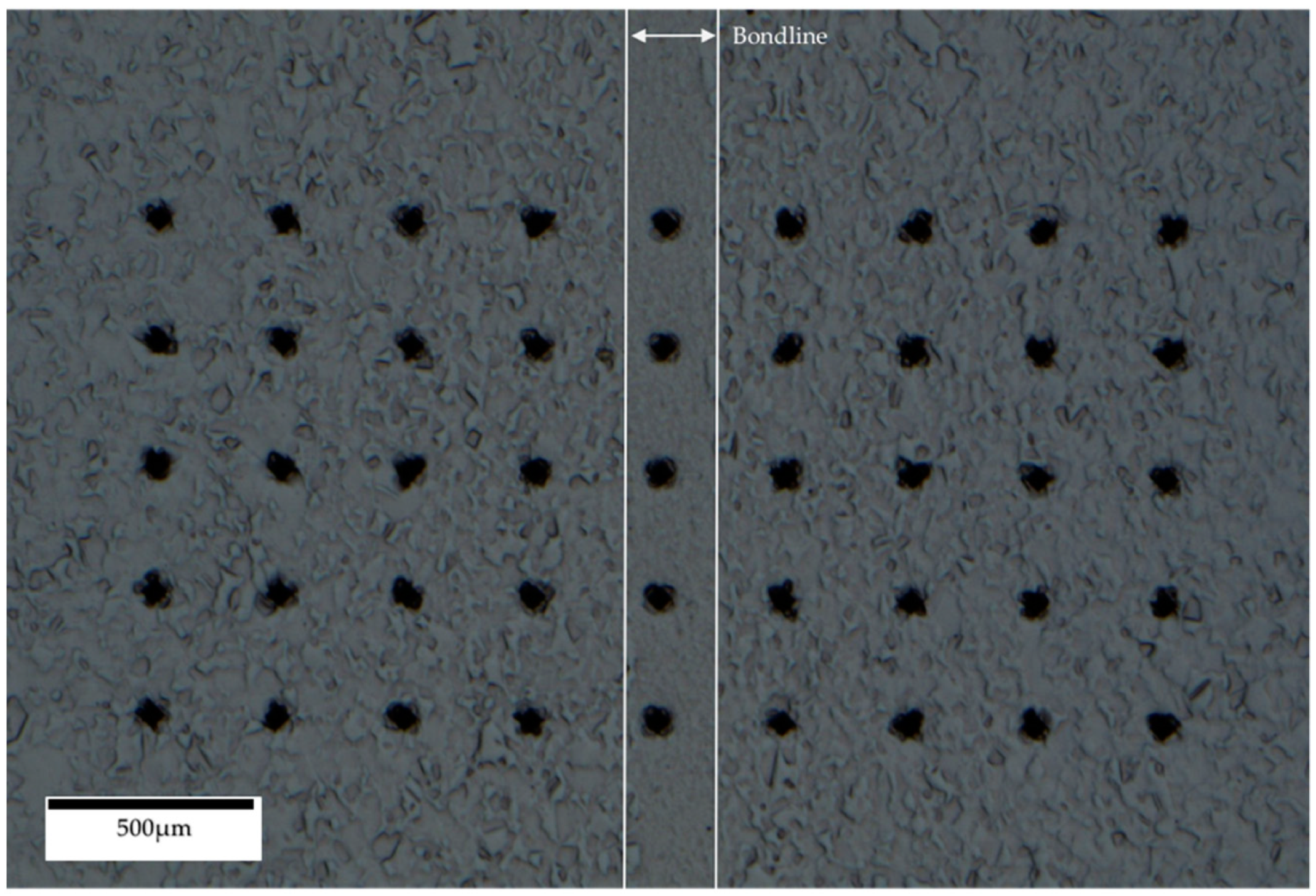
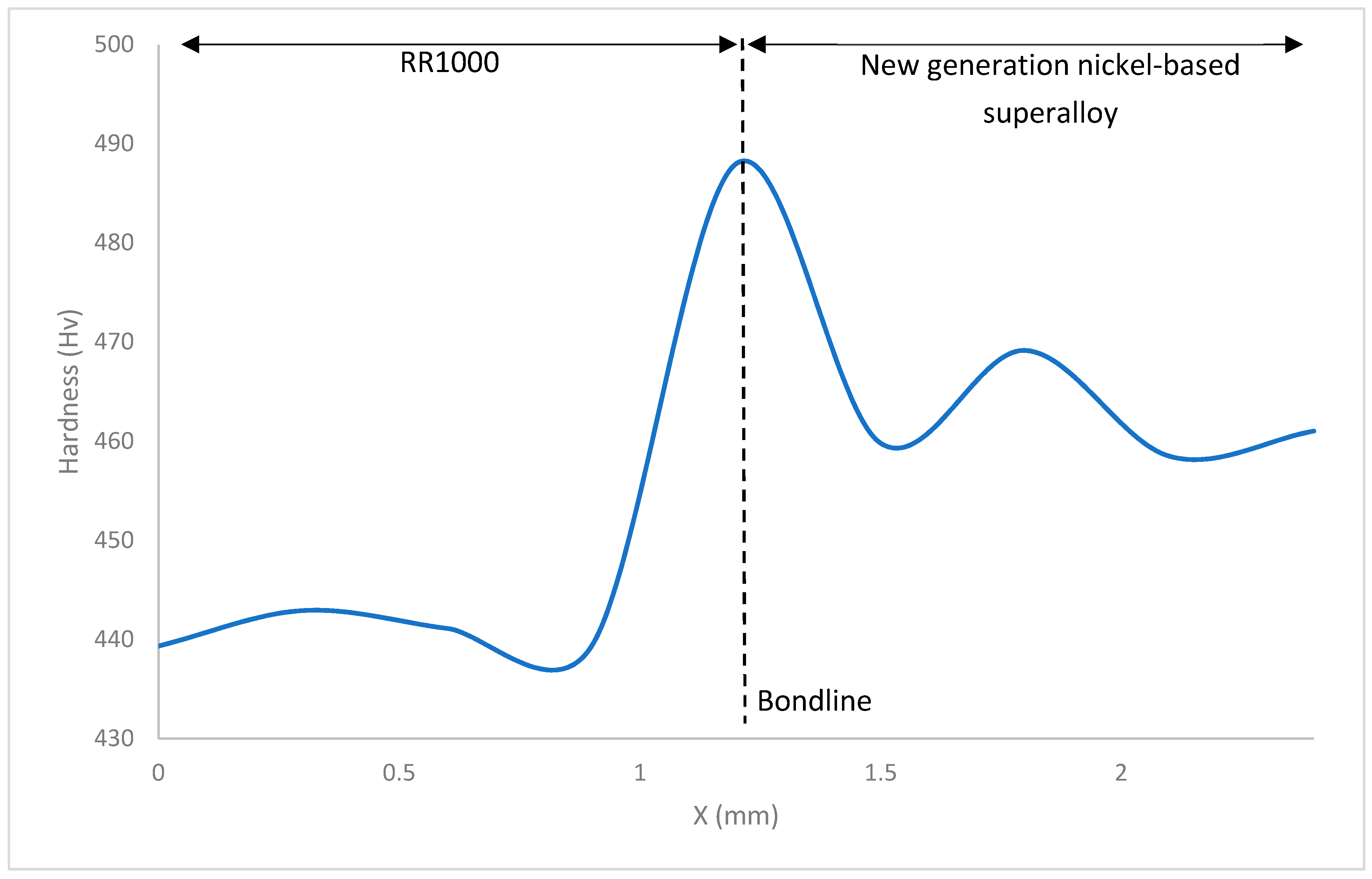
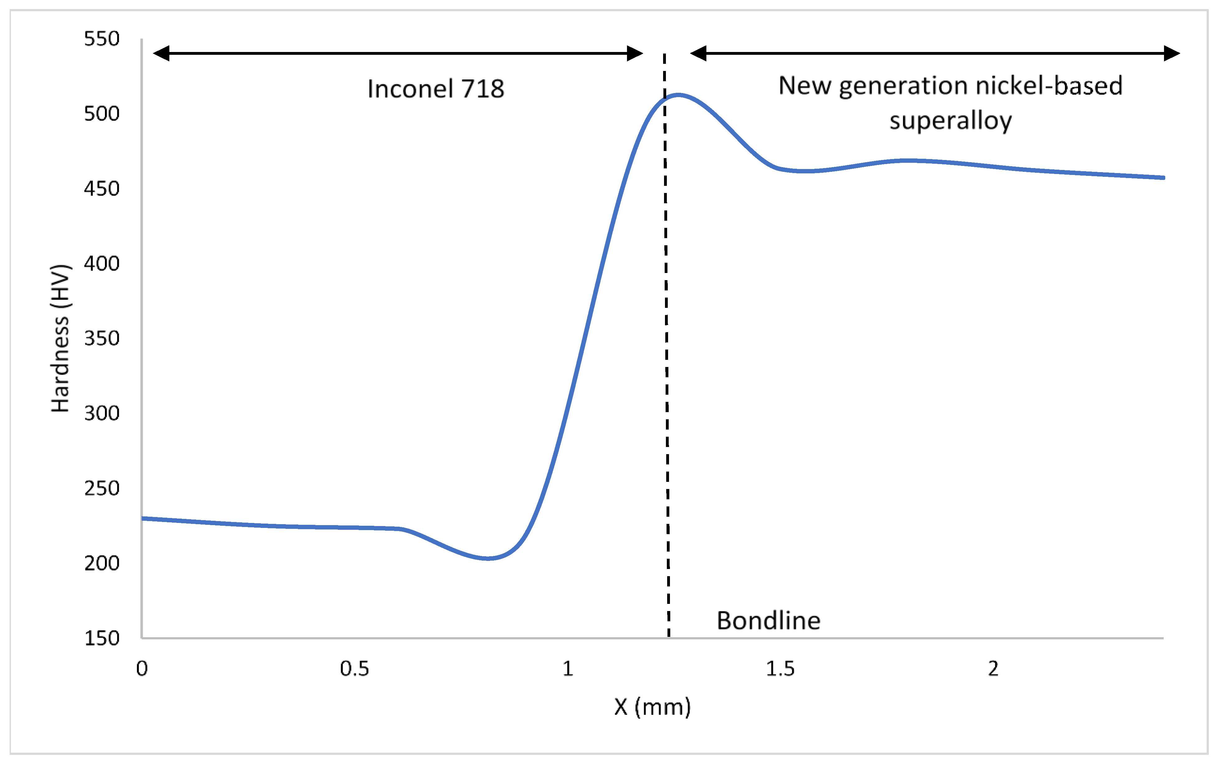
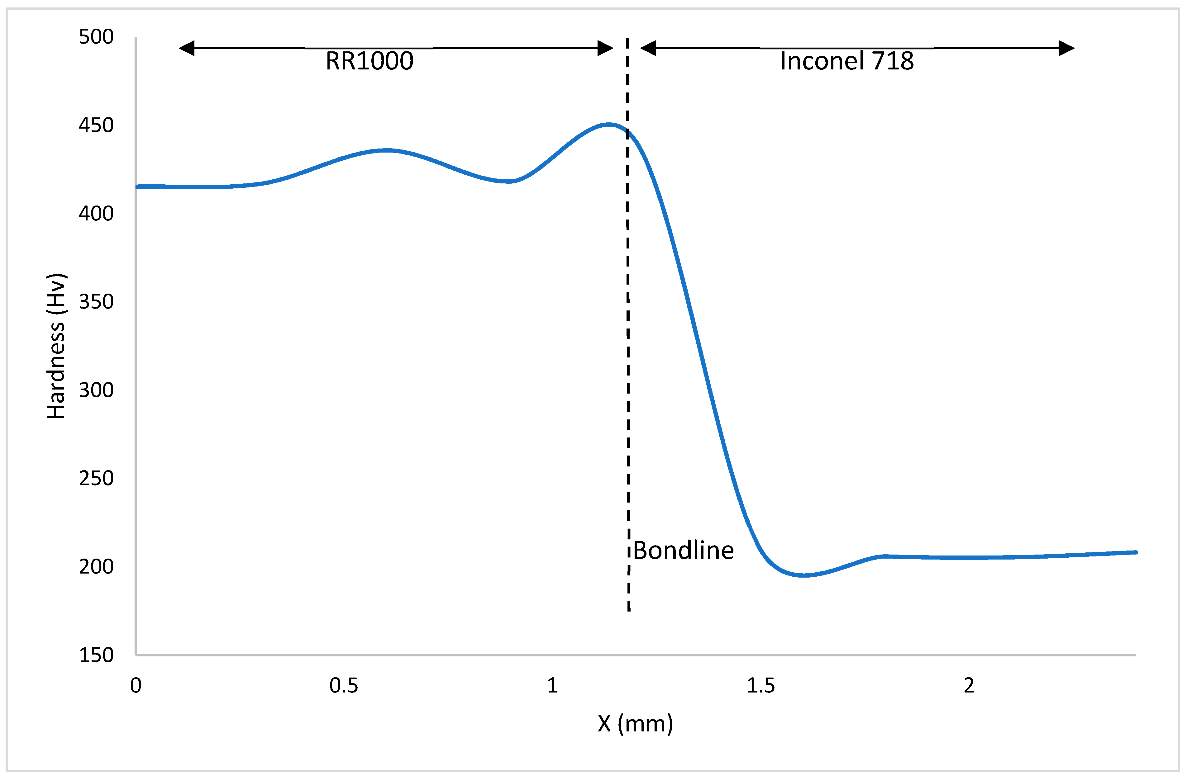
3.4. Bond Microhardness
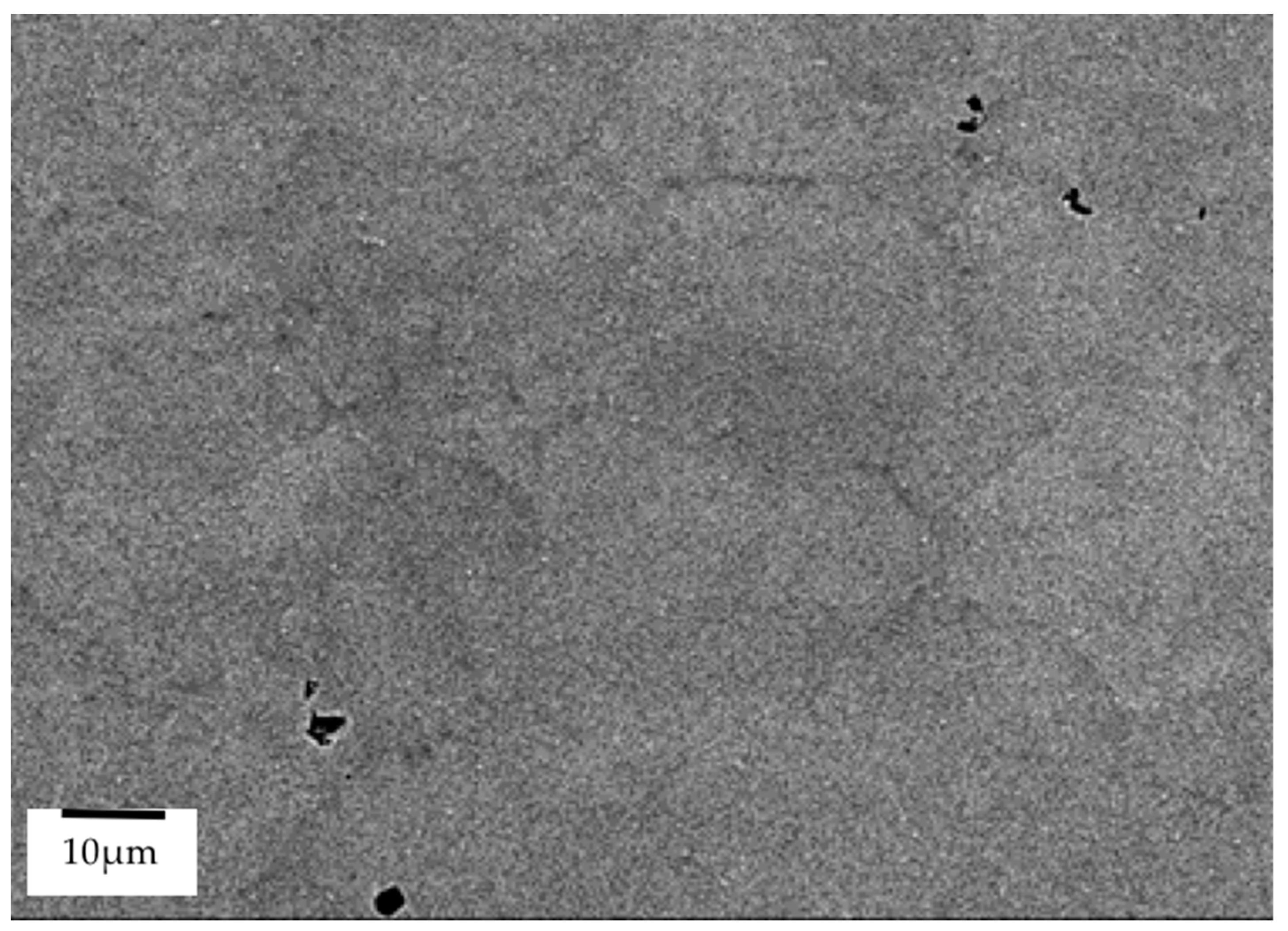
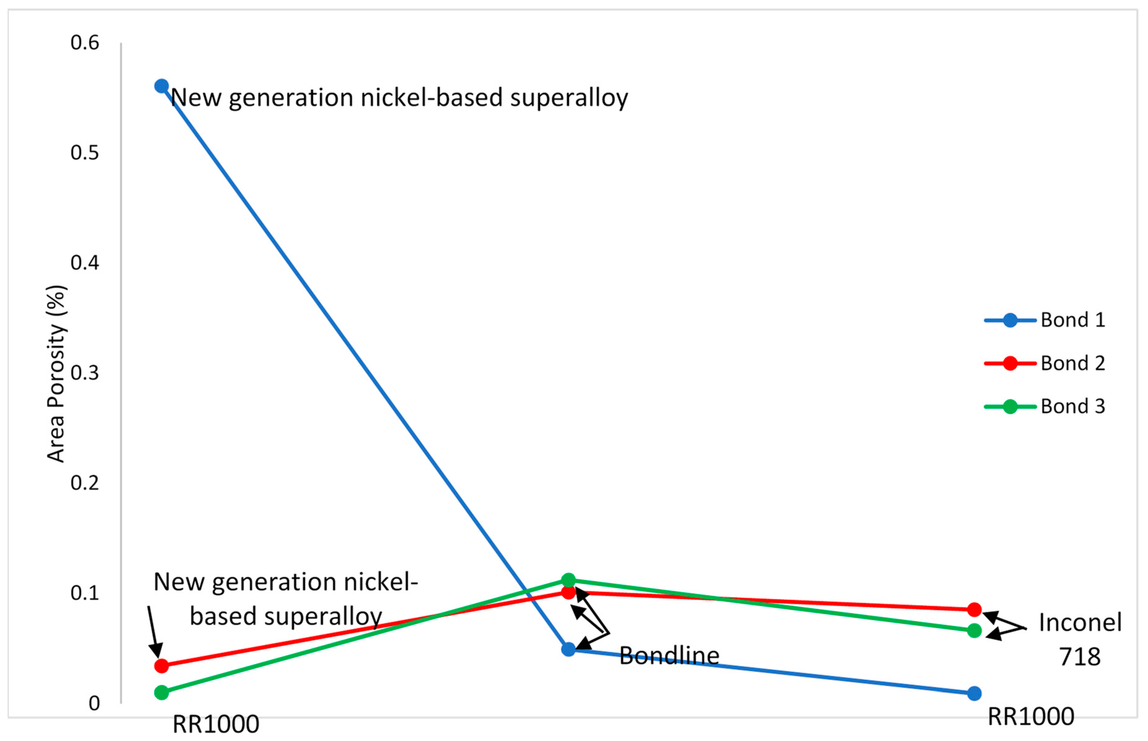
3.5. Porosity
4. Conclusions
- Bondline regions have a much finer microstructure with an increased volume of grains that are smaller in size than those of the base materials bonded.
- The bondline region provides an area of increased hardness and this relates to the Hall–Petch relationship.
- An increased volume of finer precipitates at bondlines and the nearby HAZ contributes to increased hardness in these regions and this is a trend also observed in inertia friction welding of nickel-based superalloys.
- γ′ strengthened alloys proved to be harder than γ″ strengthened alloys after being subjected to elevated bonding temperatures as the γ″ strengthening precipitates decompose into the stable δ phase.
- There is no clear trend between porosity in the bondline and surrounding base material for PIB of dissimilar materials as bondlines with reduced porosity compared to their surrounding material and bondlines with increasing porosity compared to their surrounding materials were both observed in this study.
- Further work is required to understand fully the mechanical property effects of PIB for dissimilar metals.
Author Contributions
Funding
Institutional Review Board Statement
Informed Consent Statement
Data Availability Statement
Acknowledgments
Conflicts of Interest
References
- Pollock, T.M.; Tin, S. Nickel-Based Superalloys for Advanced Turbine Engines: Chemistry, Microstructure and Properties. J. Propuls. Power 2006, 22, 361–374. [Google Scholar] [CrossRef]
- Kumar, B.V.R.R. A Review on Blisk Technology. Int. J. Innov. Res. Sci. Eng. Technol. 2013, 2, 1353–1358. [Google Scholar]
- Aschenbruck, J.; Adamczuk, R.; Seume, J.R. Recent Progress in Turbine Blade and Compressor Blisk Regeneration. Procedia CIRP 2014, 22, 256–262. [Google Scholar] [CrossRef]
- Wisbey, J.L. Joining, Repair and Structural Integrity of IN718 Aerospace Material. Ph.D. Thesis, Swansea University, Swansea, UK, 2013. [Google Scholar]
- Davies, P.; Johal, A.; Davies, H.; Marchisio, S. Powder interlayer bonding of titanium alloys: Ti-6Al-2Sn-4Zr-6Mo and Ti-6Al-4V. Int. J. Adv. Manuf. Technol. 2019, 103, 441–452. [Google Scholar] [CrossRef]
- Watkins, I.T.; Davies, H.M.; Stanners, O.G.; Marchisio, S. Powder interlayer bonding of geometrically complex Ti-6Al-4V parts. Int. J. Adv. Manuf. Technol. 2019, 106, 3629–3639. [Google Scholar] [CrossRef]
- Stanners, O.; John, S.; Davies, H.M.; Watkins, I.; Marchisio, S. The Effect of Processing Variables on Powder Interlayer Bonding in Nickel-Based Superalloys. Materials 2020, 13, 601. [Google Scholar] [CrossRef] [PubMed]
- Akca, E.; Gürsel, A. The importance of interlayers in diffusion welding—A review. Period. Eng. Nat. Sci. (PEN) 2015, 3. [Google Scholar] [CrossRef]
- Lee, H.-S. Diffusion bonding of metal alloys in aerospace and other applications. Weld. Join. Aerosp. Mater. 2012, 320–344. [Google Scholar] [CrossRef]
- Tuppen, S.J.; Bache, M.R.; Voice, W.E. Structural integrity of diffusion bonds in Ti–6Al–4V processed via low cost route. Mater. Sci. Technol. 2006, 22, 1423–1430. [Google Scholar] [CrossRef]
- Allazadeh, M.R.; Zuelli, N. Metrology and Microscopy Analysis of Multisheet Packs Manufactured via Superplastic Forming to Study Possible Diffusion Bonding. Procedia Eng. 2017, 183, 251–256. [Google Scholar] [CrossRef]
- Kumar, S.S.; Ravisankar, B. An Evaluation of Quality of Joints of Two Dissimilar Metals by Diffusion Bonding using Ultrasonic C Scan. Mater. Manuf. Process. 2015, 31, 2084–2090. [Google Scholar] [CrossRef]
- Forsdike, J. Novel Joining and Repair of Aerospace Materials. Ph.D. Thesis, Swansea University, Swansea, UK, 2009. [Google Scholar]
- Daus, F.; Li, H.Y.; Baxter, G.; Bray, S.; Bowen, P. Mechanical and microstructural assessments of RR1000 to IN718 inertia welds –effects of welding parameters. Mater. Sci. Technol. 2007, 23, 1424–1432. [Google Scholar] [CrossRef]
- Li, W.; Vairis, A.; Preuss, M.; Ma, T. Linear and rotary friction welding review. Int. Mater. Rev. 2016, 61, 71–100. [Google Scholar] [CrossRef]
- Morton, T.W. Solid State Joining od Dissimilar Titanium Alloys. Ph.D. Thesis, University of Washington, Seattle, WA, USA, 2015. [Google Scholar]
- Esposito, L.; Bertocco, A.; Cricrì, G.; Rosiello, V. Welding-repair effect on F357-T6 aluminum castings: Analysis of fatigue life. Int. J. Adv. Manuf. Technol. 2019, 102, 3699–3706. [Google Scholar] [CrossRef]
- Pleydell-Pearce, C. Resistance Bonding of Dissimilar Alloys Using a Powder Interlayer: A Feasibility Study. Ph.D. Thesis, Swansea University, Swansea, UK, 2008. [Google Scholar]
- Ye, R.; Li, H.; Ding, R.; Doel, T.; Bray, S.; Walpole, A.; Bowen, P. Microstructure and microhardness of dissimilar weldment of Ni-based superalloys IN718-IN713LC. Mater. Sci. Eng. A 2020, 774, 138894. [Google Scholar] [CrossRef]
- Reed, R.; Rae, C. Physical Metallurgy of the Nickel-Based Superalloys. Phys. Metall. 2014, 2215–2290. [Google Scholar] [CrossRef]
- May, J.; Hardy, M.; Bache, M.; Kaylor, D.D. Microstructure and Mechanical Properties of an Advanced Nickel-Based Superalloy in the as-HIP Form. Adv. Mater. Res. 2011, 278, 265–270. [Google Scholar] [CrossRef]
- Kitaguchi, H. Microstructure-Property Relationship in Advanced Ni-Based Superalloys. Metall. Adv. Mater. Process. 2012. [Google Scholar] [CrossRef]
- Mignanelli, P.; Jones, N.; Pickering, E.; Messé, O.; Rae, C.; Hardy, M.; Stone, H. Gamma-gamma prime-gamma double prime dual-superlattice superalloys. Scr. Mater. 2017, 136, 136–140. [Google Scholar] [CrossRef]
- Mitchell, R.; Lemsky, J.; Ramanathan, R.; Li, H.; Perkins, K.; Connor, L. Process Development and Microstructure and Mechanical Property Evaluation of a Dual Microstructure Heat Treated Advanced Nickel Disc Alloy. Superalloys 718, 625, 706 and Various Derivatives (2001). 2008. Available online: https://www.tms.org/superalloys/10.7449/2008/Superalloys_2008_347_356.pdf (accessed on 7 April 2021).
- Available online: https://www.specialmetals.com/assets/smc/documents/inconel_alloy_718.pdf (accessed on 7 April 2021).
- Torres-Caceres, J. A Framework for Miniaturized Mechanical Characterization of Tensile, Creep, and Fatigue Properties of SLM Alloys. Ph.D. Thesis, University of Central Florida, Orlando, FL, USA, 2018. [Google Scholar]
- Lehto, P.; Remes, H.; Saukkonen, T.; Hänninen, H.; Romanoff, J. Influence of grain size distribution on the Hall–Petch relationship of welded structural steel. Mater. Sci. Eng. A 2014, 592, 28–39. [Google Scholar] [CrossRef]
- Preuss, M.; Withers, P.; Baxter, G. A comparison of inertia friction welds in three nickel base superalloys. Mater. Sci. Eng. A 2006, 437, 38–45. [Google Scholar] [CrossRef]
- Huang, Z.; Li, H.; Baxter, G.; Bray, S.; Bowen, P. Electron microscopy characterization of the weld line zones of an inertia friction welded superalloy. J. Mater. Process. Technol. 2011, 211, 1927–1936. [Google Scholar] [CrossRef]


| Bond | Specimen 1 | Specimen 2 | Time (min) | Temperature (°C) | Force (kN) | Interlayer |
|---|---|---|---|---|---|---|
| 1 | New generation nickel-based superalloy | RR1000 | 30 | 1050 | 5 | New generation nickel-based superalloy |
| 2 | New generation nickel-based superalloy | Inconel 718 | 30 | 970 | 6 | New generation nickel-based superalloy |
| 3 | RR1000 | Inconel 718 | 30 | 970 | 6 | RR1000 |
| Bond | Length Deformation | Diameter Deformation |
|---|---|---|
| 1 | −2.659% | 46.3% |
| 2 | −0.013% | 5.5% |
| 3 | −1.415 | 11.5% |
| As-Received Material | % Area Porous |
|---|---|
| New generation nickel-based superalloy | 0.037 |
| RR1000 | 0.006 |
| Inconel 718 | 0.025 |
| Bond | Material | % Area Porous |
|---|---|---|
| 1 | New generation nickel-based superalloy | 0.561 |
| Bondline | 0.049 | |
| RR1000 | 0.009 | |
| 2 | New generation nickel-based superalloy | 0.034 |
| Bondline | 0.101 | |
| Inconel 718 | 0.085 | |
| 3 | RR1000 | 0.010 |
| Bondline | 0.112 | |
| Inconel 718 | 0.066 |
Publisher’s Note: MDPI stays neutral with regard to jurisdictional claims in published maps and institutional affiliations. |
© 2021 by the authors. Licensee MDPI, Basel, Switzerland. This article is an open access article distributed under the terms and conditions of the Creative Commons Attribution (CC BY) license (https://creativecommons.org/licenses/by/4.0/).
Share and Cite
Stanners, O.; Russell, J.; John, S.; Davies, H.M.; Marchisio, S. Powder Interlayer Bonding of Nickel-Based Superalloys with Dissimilar Chemistries. Materials 2021, 14, 2029. https://doi.org/10.3390/ma14082029
Stanners O, Russell J, John S, Davies HM, Marchisio S. Powder Interlayer Bonding of Nickel-Based Superalloys with Dissimilar Chemistries. Materials. 2021; 14(8):2029. https://doi.org/10.3390/ma14082029
Chicago/Turabian StyleStanners, Olivia, James Russell, Sean John, Helen M. Davies, and Silvia Marchisio. 2021. "Powder Interlayer Bonding of Nickel-Based Superalloys with Dissimilar Chemistries" Materials 14, no. 8: 2029. https://doi.org/10.3390/ma14082029
APA StyleStanners, O., Russell, J., John, S., Davies, H. M., & Marchisio, S. (2021). Powder Interlayer Bonding of Nickel-Based Superalloys with Dissimilar Chemistries. Materials, 14(8), 2029. https://doi.org/10.3390/ma14082029