
Influence of Welding Speed on Fracture Toughness of Friction Stir Welded AA2024-T351 Joints

 ,
, 
 ,
, 
Abstract
1. Introduction
2. Material and Experimental Procedure
2.1. Material
2.2. Friction Stir Welding
2.3. Microstructural Analysis
2.4. Hardness Testing
2.5. Fracture Testing
3. Results and Discussion
3.1. Microstructural Analysis
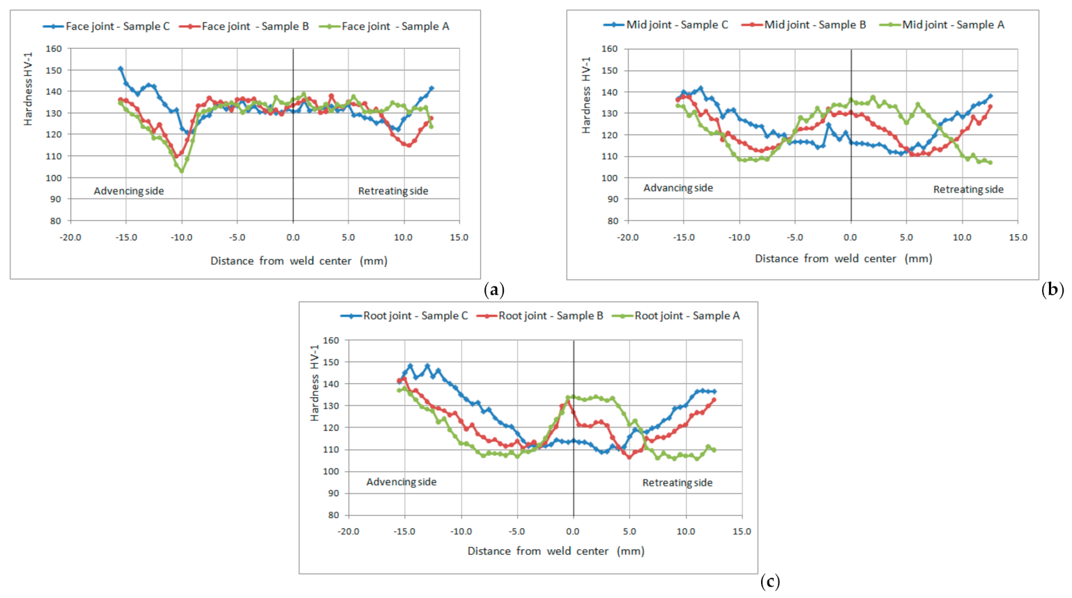
3.2. Effects Welding Parameters of FSW on Microhardness
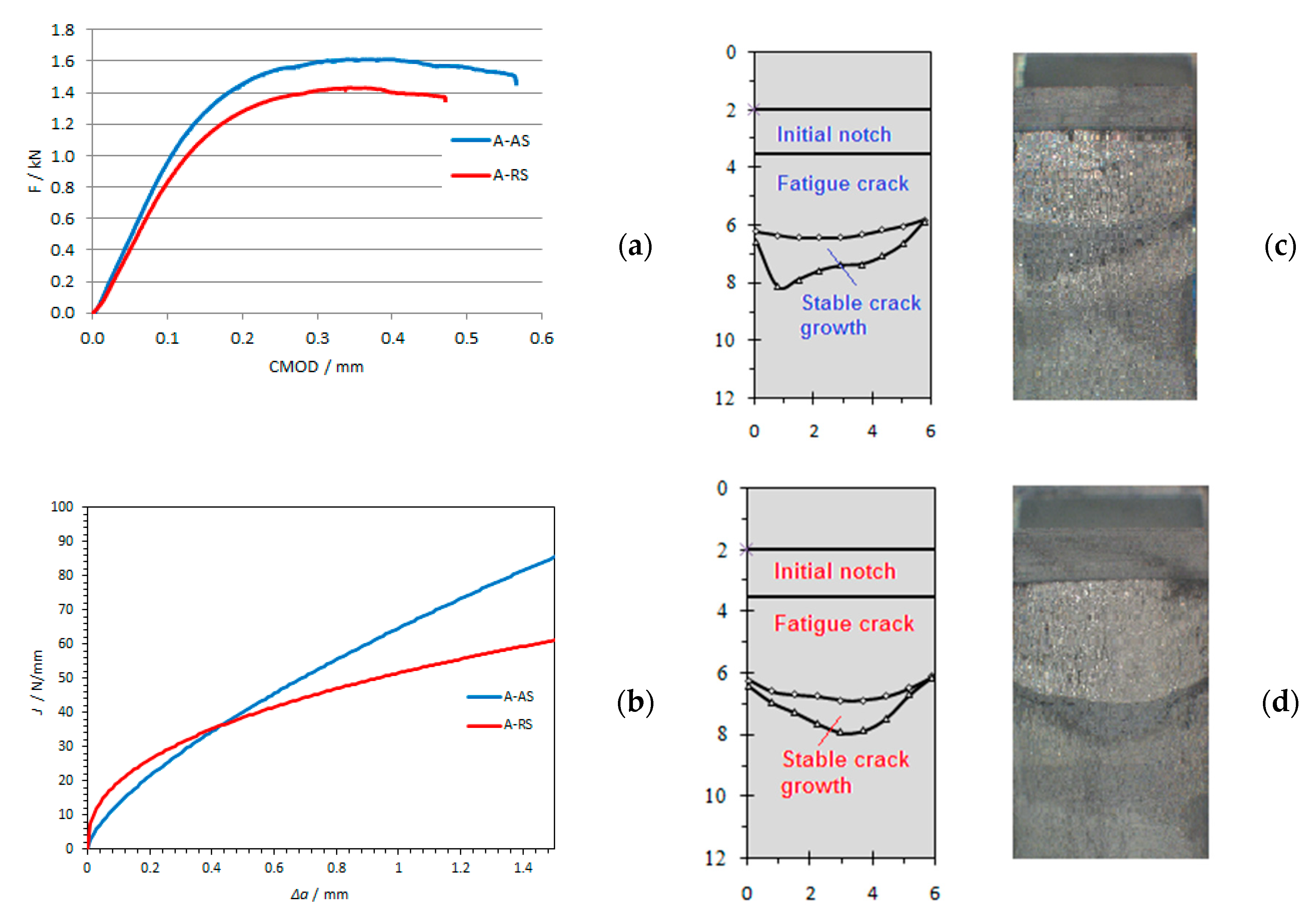
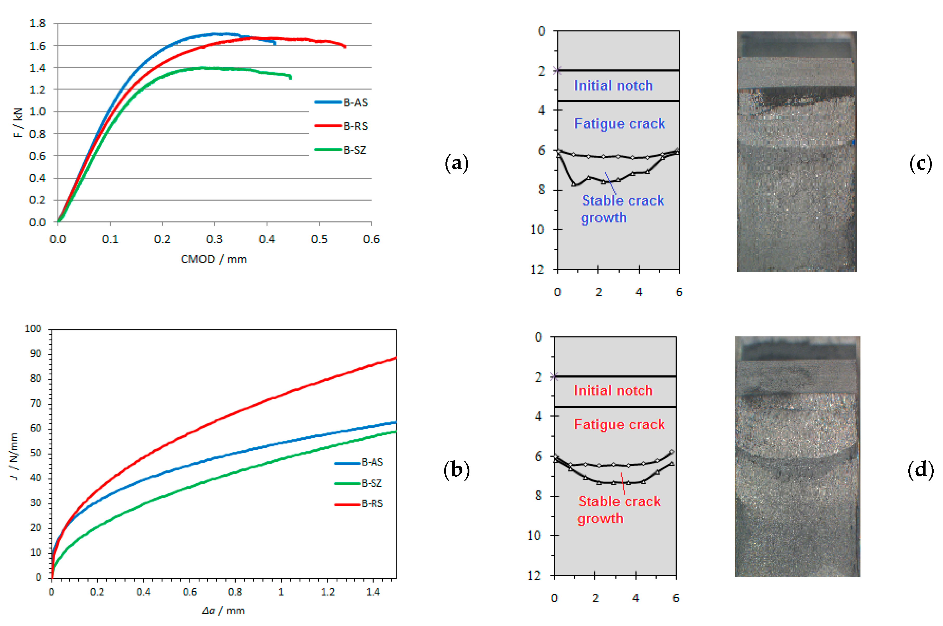
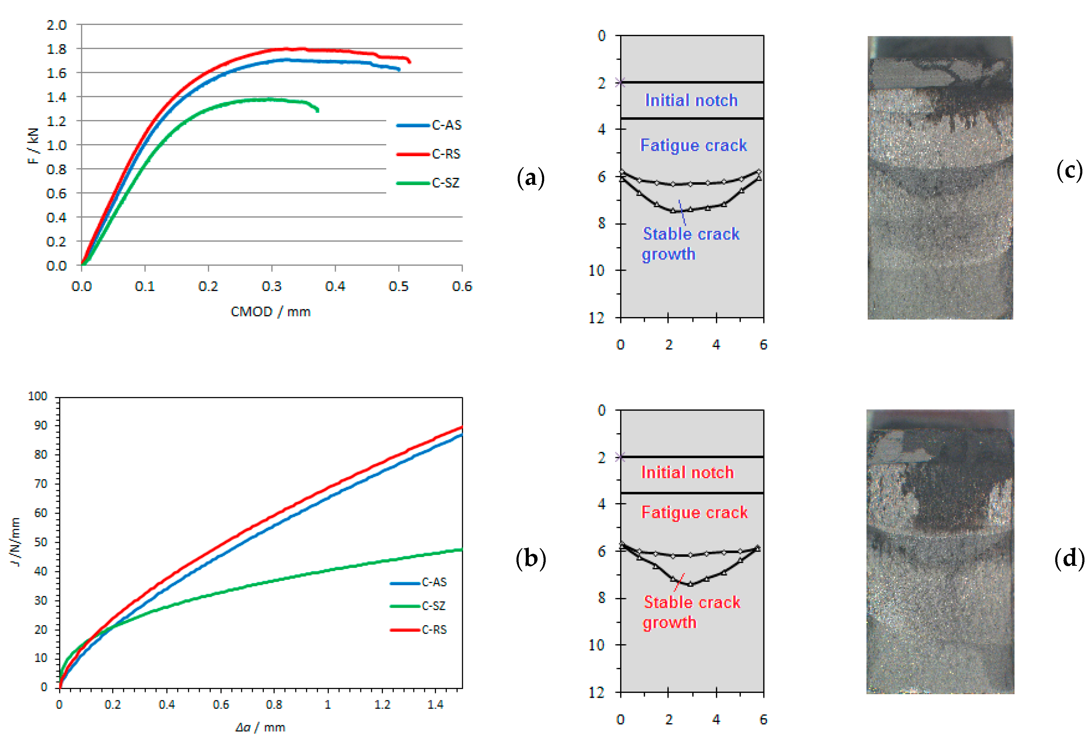
3.3. Effects Welding Parameters of FSW on Fracture Toughness
4. Conclusions
- Although at the lowest welding speed (the amount of heat generated is the largest) the grain size in the SZ is the largest; the hardness increases as the welding speed decreases, regardless of the coarser grain in the SZ. This tendency suggests that a significant increase in hardness with decreasing welding speed is not a function of grain size, but a function of particle size and distribution of the second phase and precipitate.
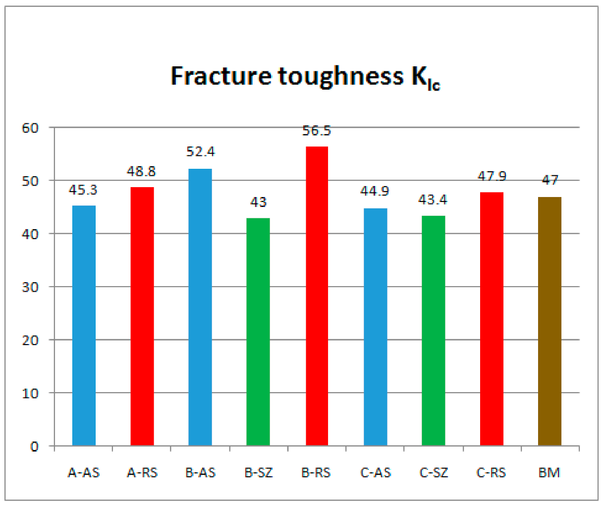
- By analyzing the results of fracture toughness, it can be concluded that for all welding samples, the structure of the welded joint on the retreating side has higher fracture toughness, i.e., it has a more pronounced resistance to crack propagation in relation to the welded joint structure on the advancing side.
- If we compare the fracture toughness of structures obtained by different welding parameters at the same position of the welded joint, it can be concluded that the highest fracture toughness has welded joints achieved by welding parameters B-750/116, followed by welded joints obtained by welding parameters A-750/73 and C-750/150, which have approximately 15% lower fracture toughness.
Author Contributions
Funding
Institutional Review Board Statement
Informed Consent Statement
Data Availability Statement
Conflicts of Interest
References
- Mazzolani, F. Aluminium Alloy Structures, 2nd ed.; CRC Press: Boca Raton, FL, USA, 2019. [Google Scholar]
- Mishra, R.S.; Ma, Z.Y. Friction stir welding and processing. Mater. Sci. Eng. R. 2005, 50, 1–78. [Google Scholar] [CrossRef]
- Thomas, W.M.; Nicholas, E.D.; Needham, J.C.; Murch, M.G.; Temple-Smith, P.; Dawes, C.J. Friction Stir Butt Welding. GB Patent No. 9125978.8, 1 December 1991. [Google Scholar]
- Heinz, A.; Haszler, A.; Keidel, C.; Moldenhauer, S.; Benedictus, R.; Miller, W. Recent development in aluminium alloys for aerospace applications. Mater. Sci. Eng. A 2000, 280, 102–107. [Google Scholar] [CrossRef]
- Su, J.Q.; Nelson, T.W.; Mishra, R.; Mahoney, M. Microstructural investigation of friction stir welded 7050-T651 aluminium. Acta Mater. 2003, 51, 713–729. [Google Scholar] [CrossRef]
- Dracup, B.J.; Arbegast, W.J. Friction Stir Welding as a Rivet Replacement Technology. SAE Tech. Pap. 1999, 14. [Google Scholar] [CrossRef]
- Threadgill, P.L.; Leonard, A.J.; Shercliff, H.R.; Withers, P.J. Friction stir welding of aluminium alloys. Int. Mater. Rev. 2009, 54, 49–93. [Google Scholar] [CrossRef]
- Malarvizhi, S.; Balasubramanian, V. Effect of welding processes on AA2219 aluminium alloy joint properties. Trans. Nonferr. Met. Soc. 2011, 21, 962–973. [Google Scholar] [CrossRef]
- Vilaça, P.; Santos, J.P.; Góis, A.; Quintino, L. Joining Aluminium Alloys Dissimilar in Thickness by Friction Stir Welding and Fusion Processes. Weld. World 2005, 49, 56–62. [Google Scholar] [CrossRef]
- El-Kassas, A.M.; Sabry, I. A Comparison between FSW, MIG and TIG Based on Total Cost Estimation for Aluminum Pipes. Eur. J. Adv. Eng. Technol. 2017, 4, 158–163. [Google Scholar]
- Mohammed, H.K.A. Comparative study between friction stir welding and metal inert gas welding of 2024-T4 aluminum alloy. ARPN J. Eng. Appl. Sci. 2011, 6, 36–40. [Google Scholar]
- Gibson, B.T.; Lammlein, D.H.; Prater, T.J.; Longhurst, W.R.; Cox, C.D.; Ballun, M.C.; Dharmaraj, K.J.; Cook, G.E.; Strauss, A.M. Friction stir welding: Process, automation, and control. J. Manuf. Process. 2014, 16, 56–73. [Google Scholar] [CrossRef]
- Abbasi, G.M.; Kokabi, A.H.; Daneshi, G.H.; Shalchi, B.; Sarrafi, R. The influence of the “ratio of rotational speed/traverse speed” (ω/v) on mechanical properties of AZ31 friction stir welds. Int. J. Mach. Tools Manufact. 2006, 46, 1983–1987. [Google Scholar] [CrossRef]
- Payganeh, G.H.; Arab, N.B.M.; Asl, Y.D.; Ghasemi, F.A.; Boroujeni, M.S. Effects of friction stir welding process parameters on appearance and strength of polypropylene composite welds. Int. J. Phys. Sci. 2011, 6, 4595–4601. [Google Scholar]
- Bertrand, R.; Robe, H.; Texier, D.; Zedan, Y.; Feulvarch, E.; Bocher, P. Analysis of AA2xxx/AA7xxx friction stir welds. J. Mater. Process Technol. 2019, 271, 312–324. [Google Scholar] [CrossRef]
- Myśliwiec, P.; Śliwa, R.E.; Ostrowski, R.; Bujny, M.; Zwolak, M. Effect of welding parameters and metal arrangement of the AA2024-T3 on the quality and strength of FSW lap joints for joining elements of landing gear beam. Arch. Metall. Mater. 2020, 65, 1205–1216. [Google Scholar]
- Radisavljević, I.; Živković, A.; Radović, N.; Grabulov, V. Influence of FSW parameters on formation quality and mechanical properties of Al 2024-T351 butt welded joints. Trans. Nonferr. Met. Soc. China 2013, 23, 3525–3539. [Google Scholar] [CrossRef]
- Moghadam, D.G.; Farhangdoost, K.; Nejad, R.M. Microstructure and Residual Stress Distributions Under the Influence of Welding Speed in Friction Stir Welded 2024 Aluminum Alloy. Met. Mater. Trans. B 2016, 47, 2048–2062. [Google Scholar] [CrossRef]
- Said, M.T.S.M.; Hamid, D.A.; Ismail, A.; Zainal, S.N.N.; Awang, M.; Rojan, M.A.; Ikram, I.M.; Makhtar, M.F. Experimental Study on Effect of Welding Parameters of Friction Stir Welding (FSW) on Aluminium AA5083 T-joint. Inf. Technol. J. 2016, 15, 99–107. [Google Scholar]
- Serio, L.M.; Palumbo, D.; De Filippis, L.A.C.; Galietti, U.; Ludovico, A.D. Effect of Friction Stir Process Parameters on the Mechanical and Thermal Behavior of 5754-H111 Aluminum Plates. Materials 2016, 9, 122. [Google Scholar] [CrossRef]
- Vilaça, P.; Quintino, L.; Dos Santos, J.F. ISTIR—Analytical thermal model for friction stir welding. J. Mater. Process. Technol. 2005, 169, 452–465. [Google Scholar] [CrossRef]
- Kosturek, R.; Śnieżek, L.; Torzewski, J.; Wachowski, M. Research on the Friction Stir Welding of Sc-Modified AA2519 Extrusion. Met. J. 2019, 9, 1024. [Google Scholar] [CrossRef]
- Khodir, S.A.; Shibayanagi, T.; Naka, M. Microstructure and Mechanical Properties of Friction Stir Welded AA2024-T3 Aluminum Alloy. Mater. Trans. 2006, 47, 185–193. [Google Scholar] [CrossRef]
- Perović, M.; Vuherer, T.; Bajić, D.; Gerić, K.; Baloš, S.; Rakin, M. Fracture toughness of base and weld metal of aluminum alloy EN AW 7049A T652 FSW joint. Zavar. Zavarene Konstr. 2018, 4, 159–167. [Google Scholar] [CrossRef]
- Barenji, R.V. Effect of tool traverse speed on microstructure and mechanical performance of friction stir welded 7020 aluminum alloy. Proc. Inst. Mech. Eng. Part L J. Mater. Des. Appl. 2015, 230, 663–673. [Google Scholar] [CrossRef]
- El-Morsy, A.W.; Ghanem, M.M.; Bahaitham, H. Effect of Friction Stir Welding Parameters on the Microstructure and Mechanical Properties of AA2024-T4 Aluminum Alloy. Eng. Technol. Appl. Sci. Res. 2018, 8, 2493–2498. [Google Scholar] [CrossRef]
- Cao, X.; Jahazi, M. Effect of welding speed on the quality of friction stir welded butt joints of a magnesium alloy. Mater. Des. 2009, 30, 2033–2042. [Google Scholar] [CrossRef]
- Ziemian, C.W.; Sharma, M.M.; Bouffard, B.D.; Nissley, T.; Eden, T.J. Effect of substrate surface roughening and cold spray coating on the fatigue life of AA2024 specimens. Mater. Des. 2014, 54, 212–221. [Google Scholar] [CrossRef]
- Ilman, M.N. Chromate inhibition of environmentally assisted fatigue crack propagation of aluminium AA2024-T3 in 3.5% NaCl solution. Int. J. Fatigue 2014, 62, 228–235. [Google Scholar] [CrossRef]
- Abazadeh, B.; Chakherlou, T.N.; Alderliesten, R.C. Effect of interference fitting and/or bolt clampiong on the fatigue behaviour of Al alloy 2024-T3 double shear lap joints in different cyclic load ranges. Int. J. Mech. Sci. 2013, 72, 2–12. [Google Scholar] [CrossRef]
- Zheng, Z.Q.; Cai, B.; Zhai, T.; Li, S.C. The behaviour of fatigue crack initiation and propagation in AA2524-T34 alloy. Mater. Sci. Eng. A 2011, 528, 2017–2022. [Google Scholar] [CrossRef]
- Liao, M. Probabilistic modelling of fatigue related microstructural parameters in aluminium alloys. Eng. Fract. Mech. 2009, 76, 668–680. [Google Scholar] [CrossRef]
- Yanbin, L.; Zhioyi, L.; Yuntao, L.; Qinkun, X.; Jie, Z. Enhanced fatigue crack propagation resistance of an Al-Cu-Mg alloy by artificial aging. Mater. Sci. Eng. A 2008, 492, 333–336. [Google Scholar] [CrossRef]
- Aydin, H.; Tutar, M.; Durmus, A. Effect of weldin parameters on tensile properties and fatigue behaviour of friction stir welded 2014-T6 aluminum alloy. TransIndian Inst. Met. 2012, 65, 21–30. [Google Scholar] [CrossRef]
- Moghadam, D.G.; Farhangdoost, K. Influence of welding parameters on fracture toughness and fatigue crack growth rate in friction stir welded nugget of 2024-T351 aluminum alloy joints. Trans. Nonferr. Met. Soc. China 2016, 26, 2567–2585. [Google Scholar] [CrossRef]
- Correia José, A.F.O.; De Jesus Abílio, M.P.; Alvesa Ana, S.F.; Lesiuk, G.; Tavares Paulo, J.S.; Moreira Pedro, M.G.P. Fatigue crack growth behaviour of the 6082-T6 aluminium using CT specimens with distinct notches. Procedia Struct. Integr. 2016, 2, 3272–3279. [Google Scholar] [CrossRef]
- Zhiqiang, Z.; Changshu, H.; Ying, L.; Jingxun, W.; Menggang, Z.; Su, Z.; Xiang, Z. Fatigue Behaviour of 7N01-T4 Aluminium Alloy Welded by Ultrasonic-Assisted Friction Stir Welding. Materials 2020, 13, 4582. [Google Scholar]
- Milčić, M.; Vuherer, T.; Radisavljević, I.; Milčić, D.; Kramberger, J. The influence of process parameters on the mechanical properties of friction-stir-welded joints of 2024 T351 aluminum alloys. Mater. Technol. 2019, 53, 771–776. [Google Scholar] [CrossRef]
- Milčić, M.; Vuherer, T.; Radisavljević, I.; Milčić, D.; Kramberger, J.; Andjelković, B. Mechanical behaviour of Al 2024 alloy welded by friction stir welding. IOP Conf. Series: Mater. Sci. Eng. 2018, 393, 1–9. [Google Scholar] [CrossRef]
- Vuherer, T.; Kramberger, J.; Milčić, D.; Milčić, M.; Glodež, S. Fatigue behaviour of friction stir welded AA-2024 aluminium alloy sheets, IOP Conf. Series: Mater. Sci. Eng. 2019, 659, 1–8. [Google Scholar]
- Milčić, M.; Burzić, Z.; Radisavljević, I.; Vuherer, T.; Milčić, D.; Grabulov, V. Experimental investigation of fatigue properties of FSW in AA-2024-T351. Procedia Struct. Integr. 2018, 13, 1977–1984. [Google Scholar] [CrossRef]
- Alcoa. Alloy 2024 Sheet and Plate. Available online: http://www.matweb.com/search/datasheet_print.aspx?matguid=67d8cd7c00a04ba29b618484f7ff7524 (accessed on 20 February 2021).
- ASTM E1820. Standard Test Method for Measurement of Fracture Toughness; ASTM International: West Conshohocken, PA, USA, 2015. [Google Scholar]


| Chemical Composition | Al | Cu | Mg | Mn | Fe | Si | Zn | Ti |
|---|---|---|---|---|---|---|---|---|
| wt. % | 90.7–94.7 | 3.8–4.9 | 1.2–1.8 | 0.3–0.9 | 0.5 | 0.5 | 0.25 | 0.15 |
| Yield Strength Reh (Mpa) | Ultimate Tensile Strength Rm (MPa) | Elongation A5 (%) | Hardness * HB | Hardness HV |
|---|---|---|---|---|
| ≥310 | ≥425 | ≥10 | 120 | 137 |
| Sample | Tool Rotation Speed n rpm | Welding Speed v mm/min | Ratio n/v rev/mm |
|---|---|---|---|
| A | 750 | 73 | 10.27 |
| B | 116 | 6.47 | |
| C | 150 | 5 |
| Sample | JIc N/mm | KIc N/m3/2 | δIc mm |
|---|---|---|---|
| A-AS | 25 | 45.3 | 0.040 |
| A-RS | 29 | 48.8 | 0.046 |
| B-AS | 33.5 | 52.4 | 0.043 |
| B-SZ | 23 | 43 | 0.035 |
| B-RS | 39 | 56.5 | 0.059 |
| C-AS | 24.6 | 44.9 | 0.037 |
| C-SZ | 23 | 43.4 | 0.029 |
| C-RS | 28 | 47.9 | 0.036 |
| BM | 27 | 47 | 0.035 |
Publisher’s Note: MDPI stays neutral with regard to jurisdictional claims in published maps and institutional affiliations. |
© 2021 by the authors. Licensee MDPI, Basel, Switzerland. This article is an open access article distributed under the terms and conditions of the Creative Commons Attribution (CC BY) license (http://creativecommons.org/licenses/by/4.0/).
Share and Cite
Milčić, M.; Milčić, D.; Vuherer, T.; Radović, L.; Radisavljević, I.; Đurić, A. Influence of Welding Speed on Fracture Toughness of Friction Stir Welded AA2024-T351 Joints. Materials 2021, 14, 1561. https://doi.org/10.3390/ma14061561
Milčić M, Milčić D, Vuherer T, Radović L, Radisavljević I, Đurić A. Influence of Welding Speed on Fracture Toughness of Friction Stir Welded AA2024-T351 Joints. Materials. 2021; 14(6):1561. https://doi.org/10.3390/ma14061561
Chicago/Turabian StyleMilčić, Miodrag, Dragan Milčić, Tomaž Vuherer, Ljubica Radović, Igor Radisavljević, and Aleksija Đurić. 2021. "Influence of Welding Speed on Fracture Toughness of Friction Stir Welded AA2024-T351 Joints" Materials 14, no. 6: 1561. https://doi.org/10.3390/ma14061561
APA StyleMilčić, M., Milčić, D., Vuherer, T., Radović, L., Radisavljević, I., & Đurić, A. (2021). Influence of Welding Speed on Fracture Toughness of Friction Stir Welded AA2024-T351 Joints. Materials, 14(6), 1561. https://doi.org/10.3390/ma14061561