
Study on Mechanical and Frost Resistance Properties of Slag and Macadam Stabilized with Cement and Fly Ash


Abstract
:1. Introduction
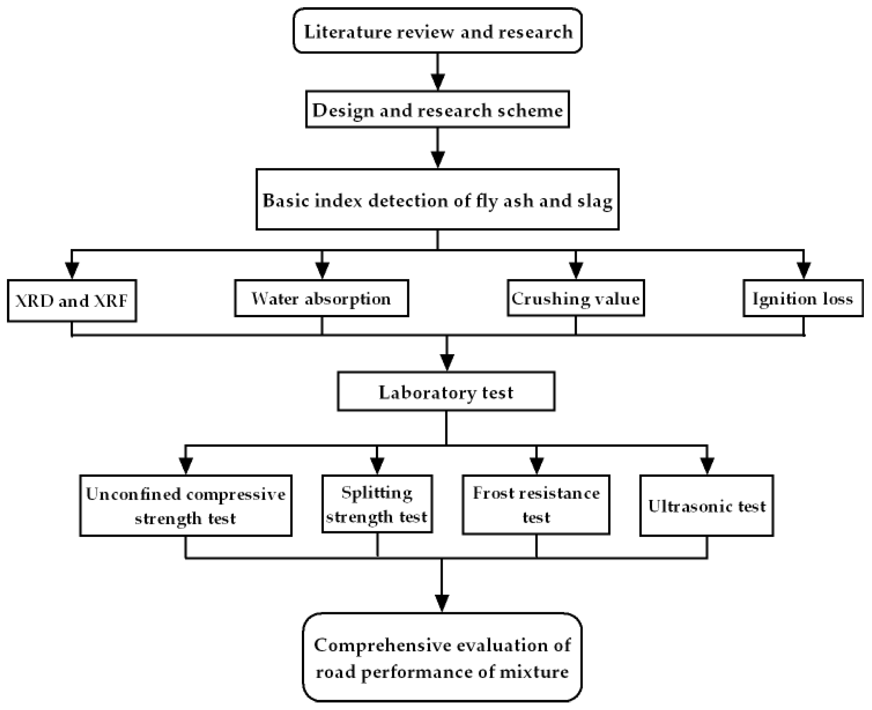
2. Materials and Methods
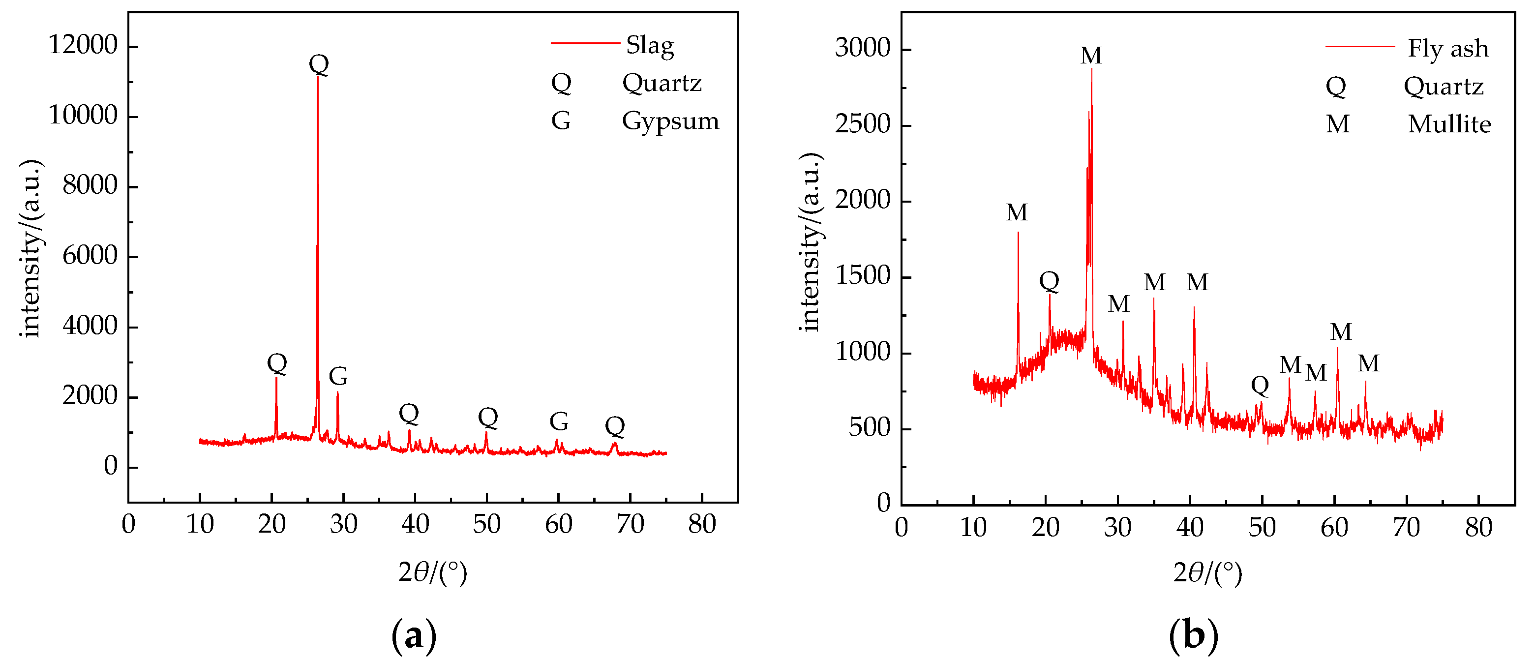
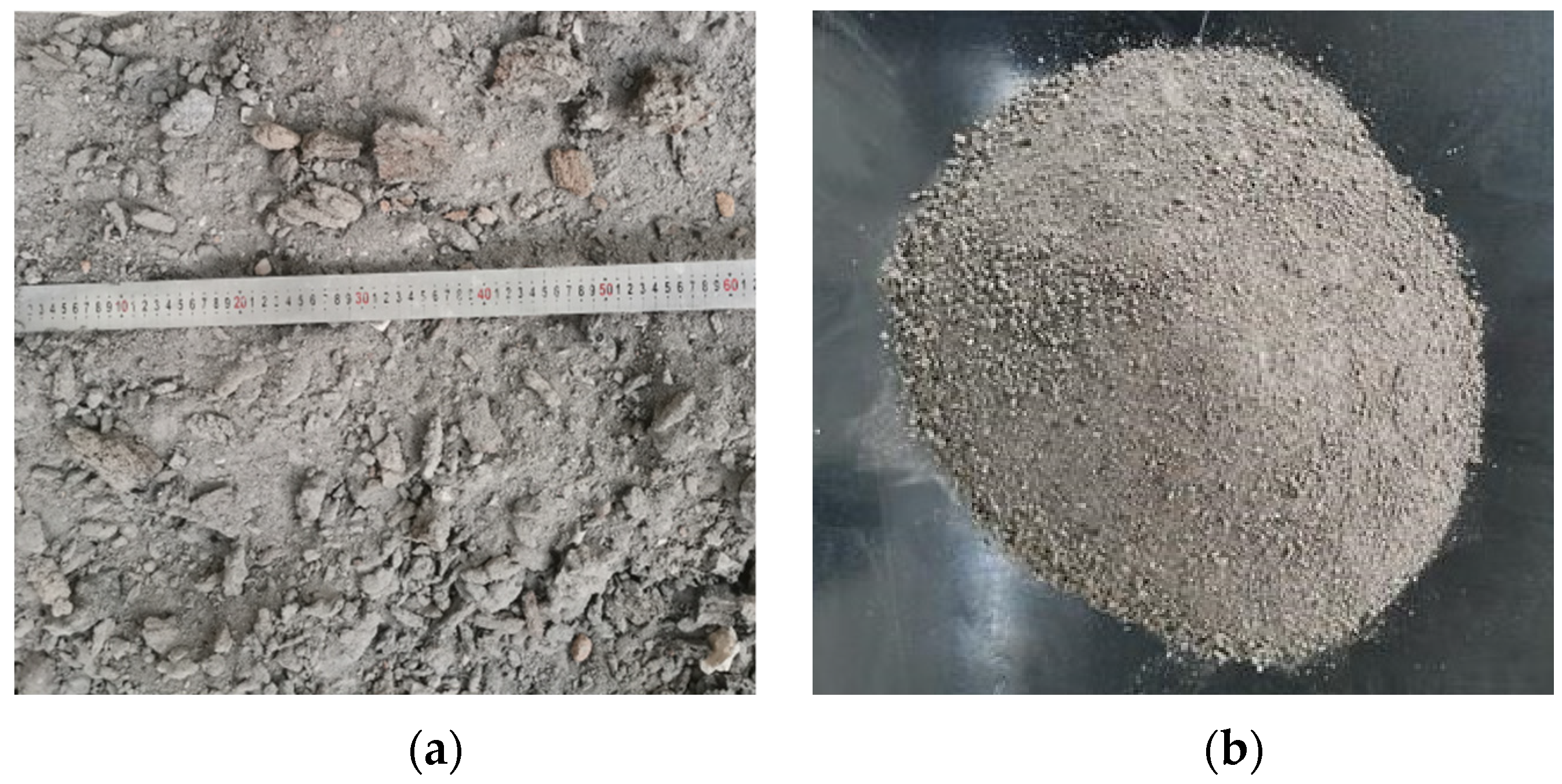
2.1. Materials
- Cement: P·O 42.5 R Ordinary Portland Cement obtained from Ningxia Horse Racing Cement Co., Ltd., Yinchuan, China;
- Fly ash: grade III fly ash produced by Thermal Power Plant in Xixia District, Yinchuan, China;
- Slag: slag produced by Thermal Power Plant in Xixia District, Yinchuan, China;
- Macadam: macadam from Helan Mountain, Yinchuan, China;
- Water: tap water.
2.2. Mix Proportion
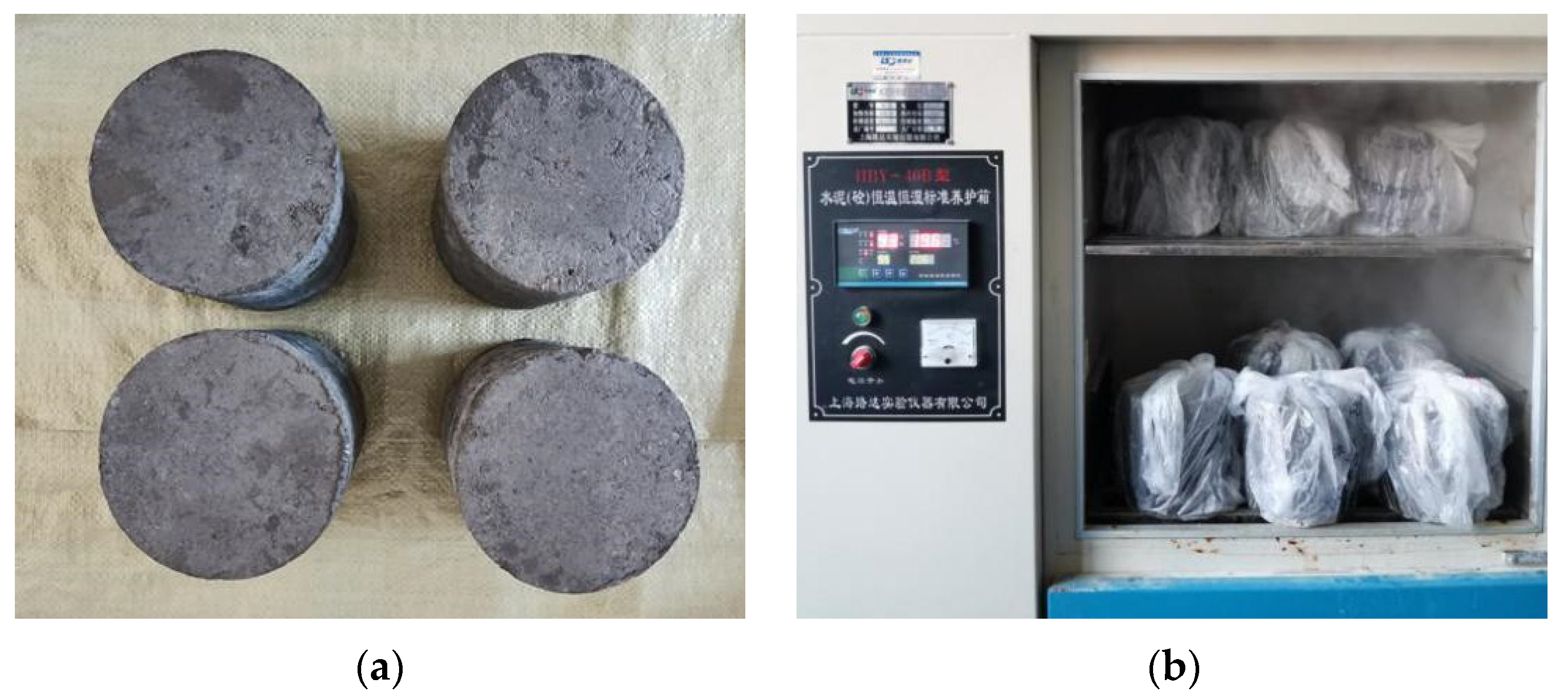
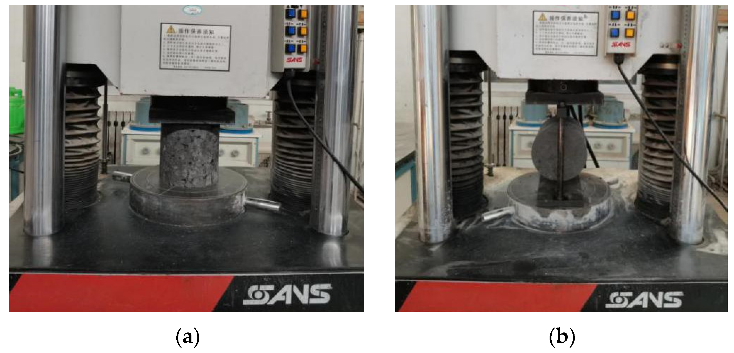
2.3. Test Methods
3. Results
3.1. Compaction Test Results
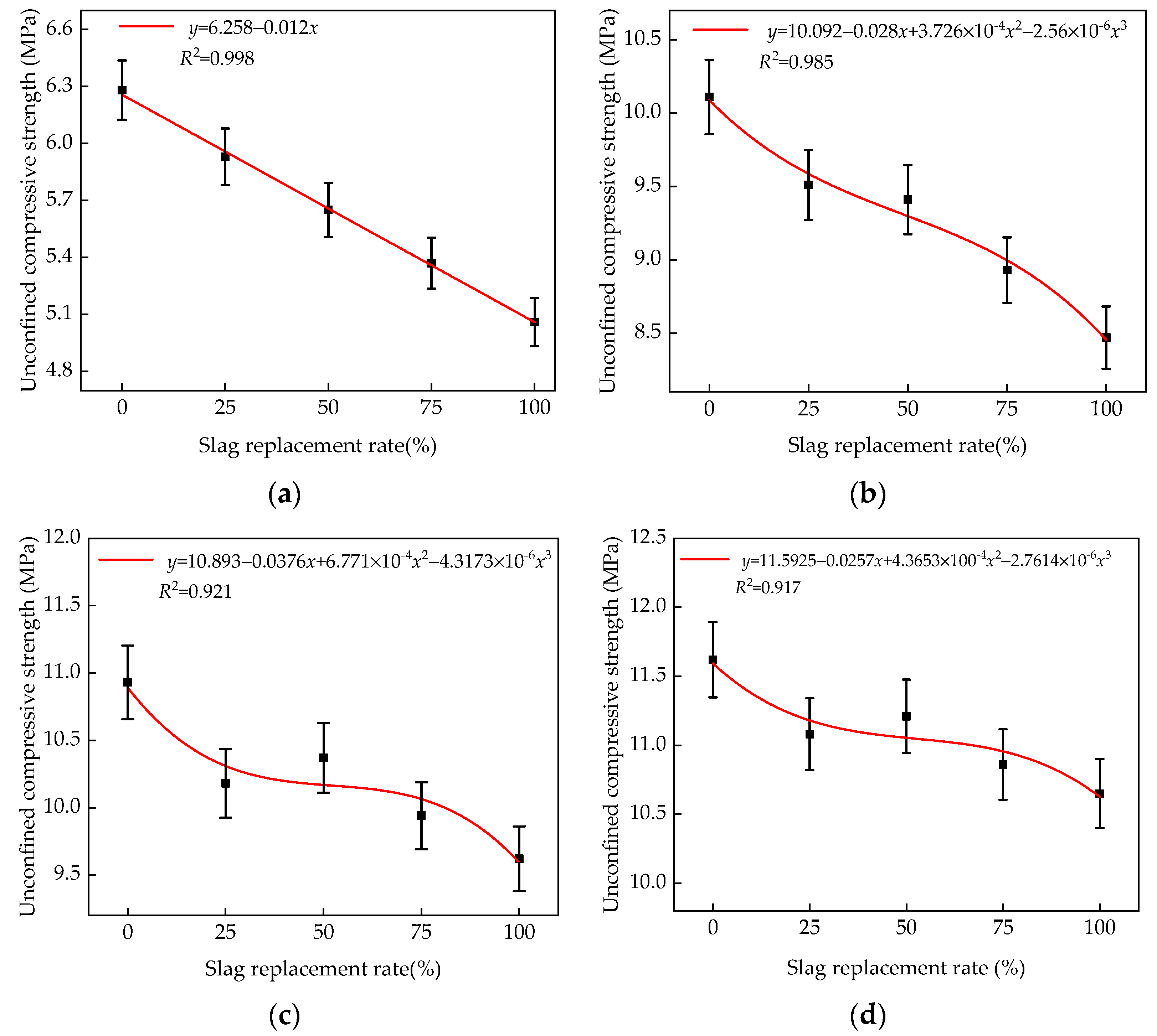
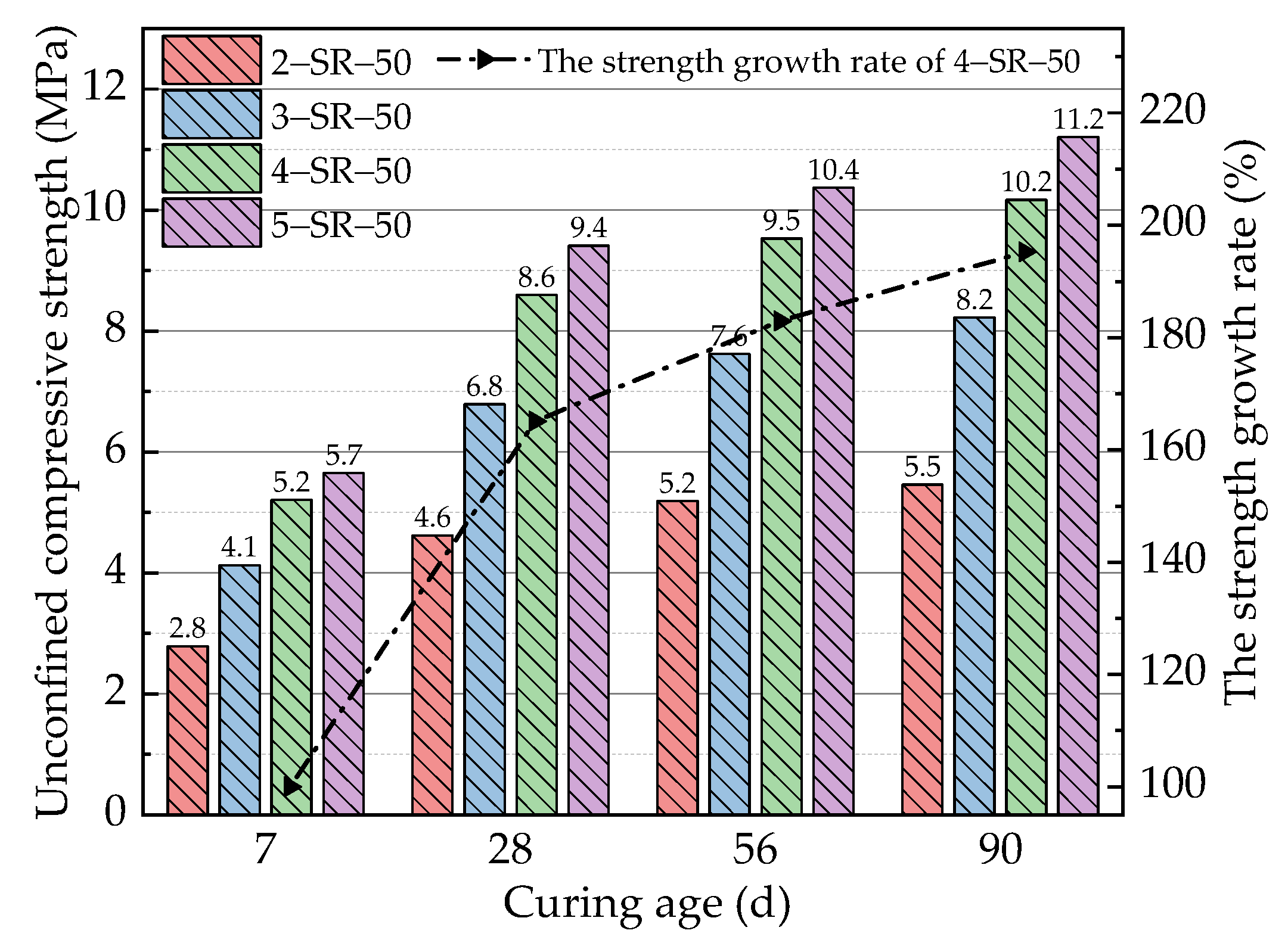
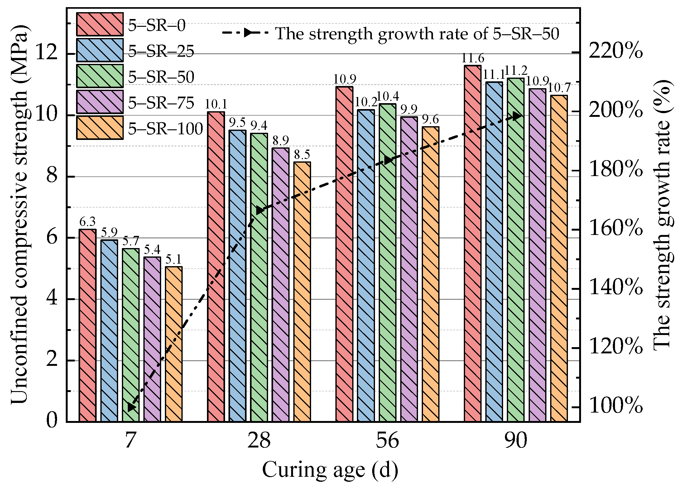
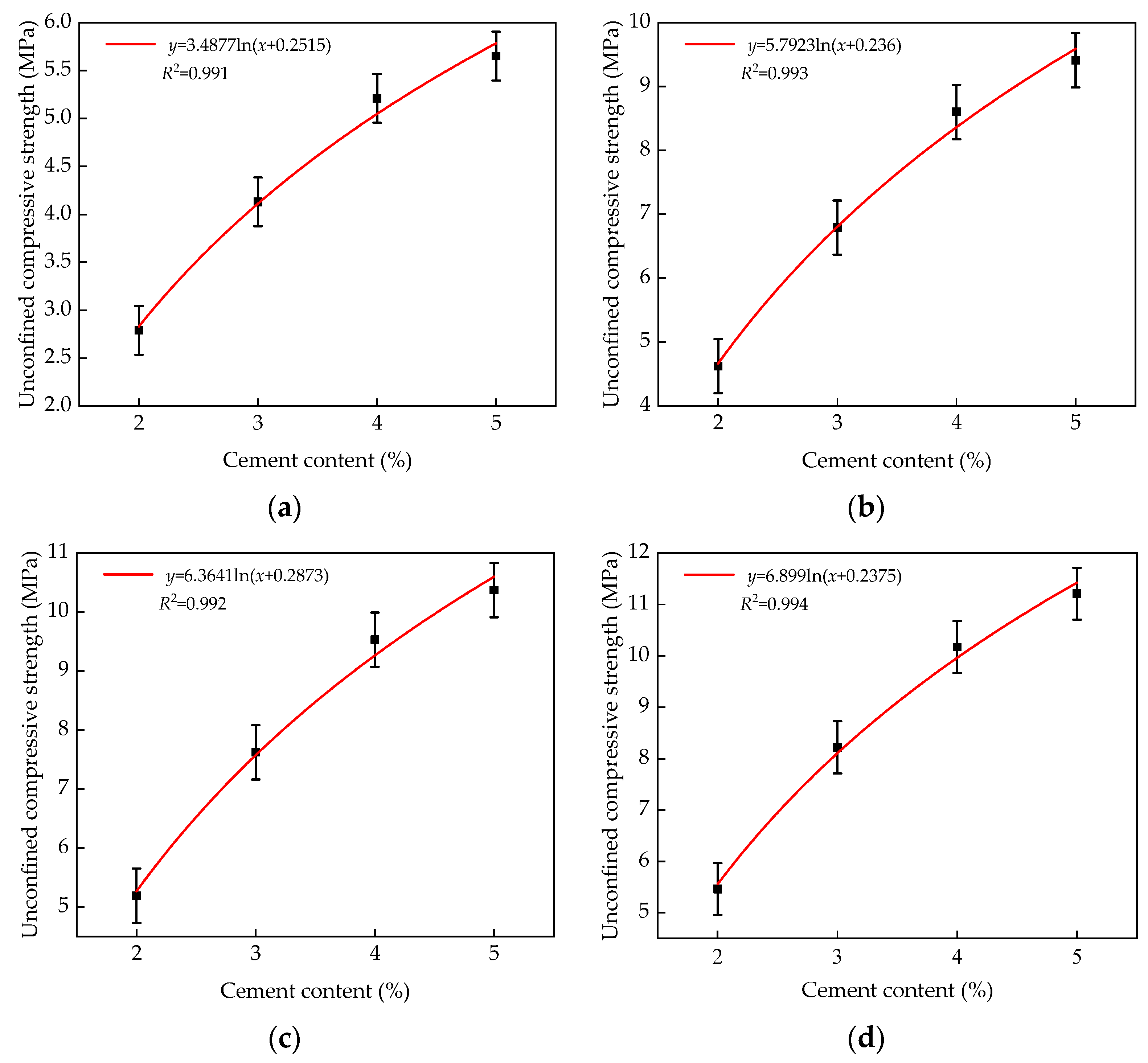
3.2. Unconfined Compressive Strength
Ca(OH)2 + Al2O3 + H2O → CaO·Al2O3·2H2O
3CaO·Al2O3 + (CaSO4·H2O) + H2O → 3CaO·Al2O3·CaSO4·2H2O
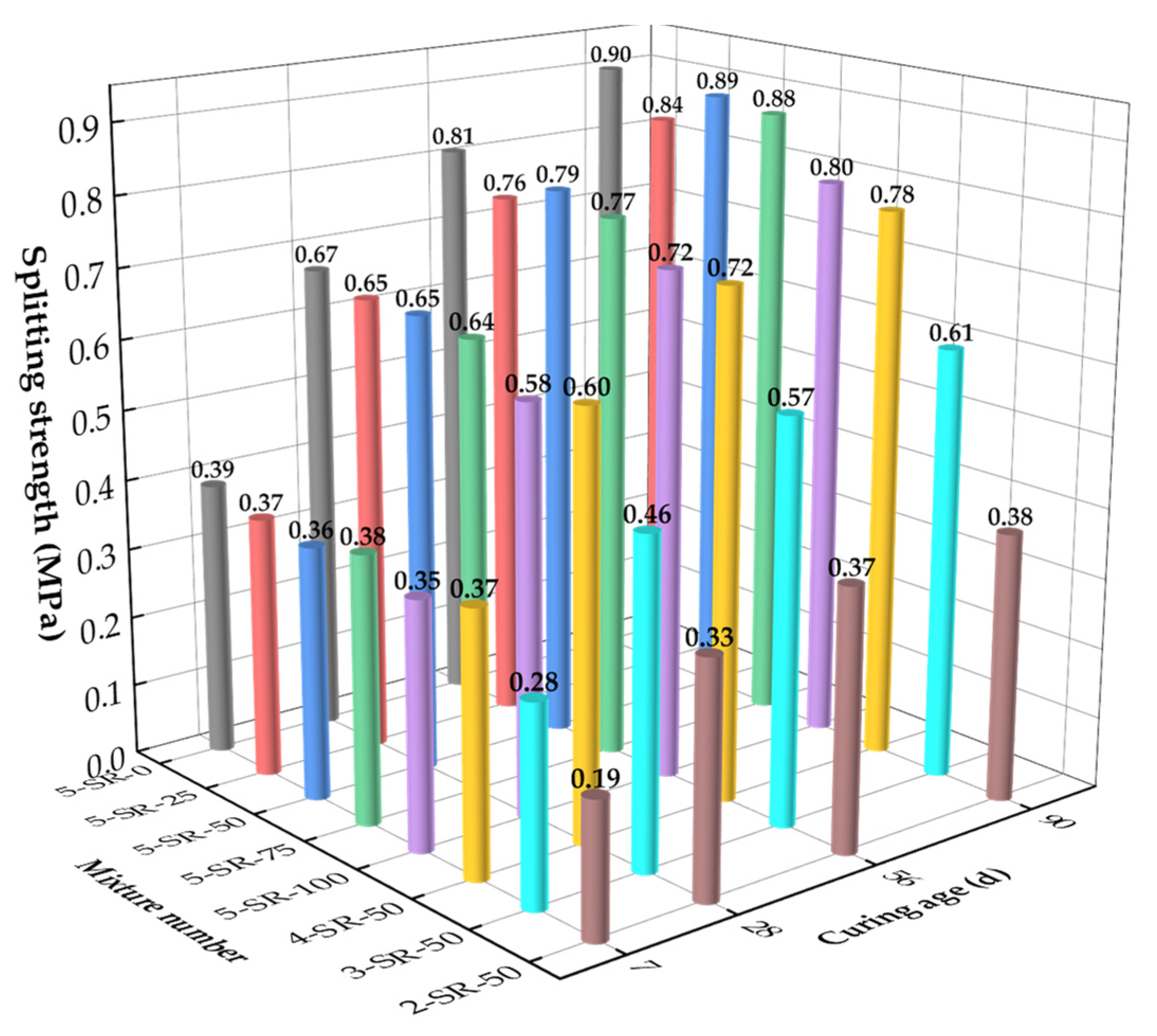
3.3. Splitting Strength
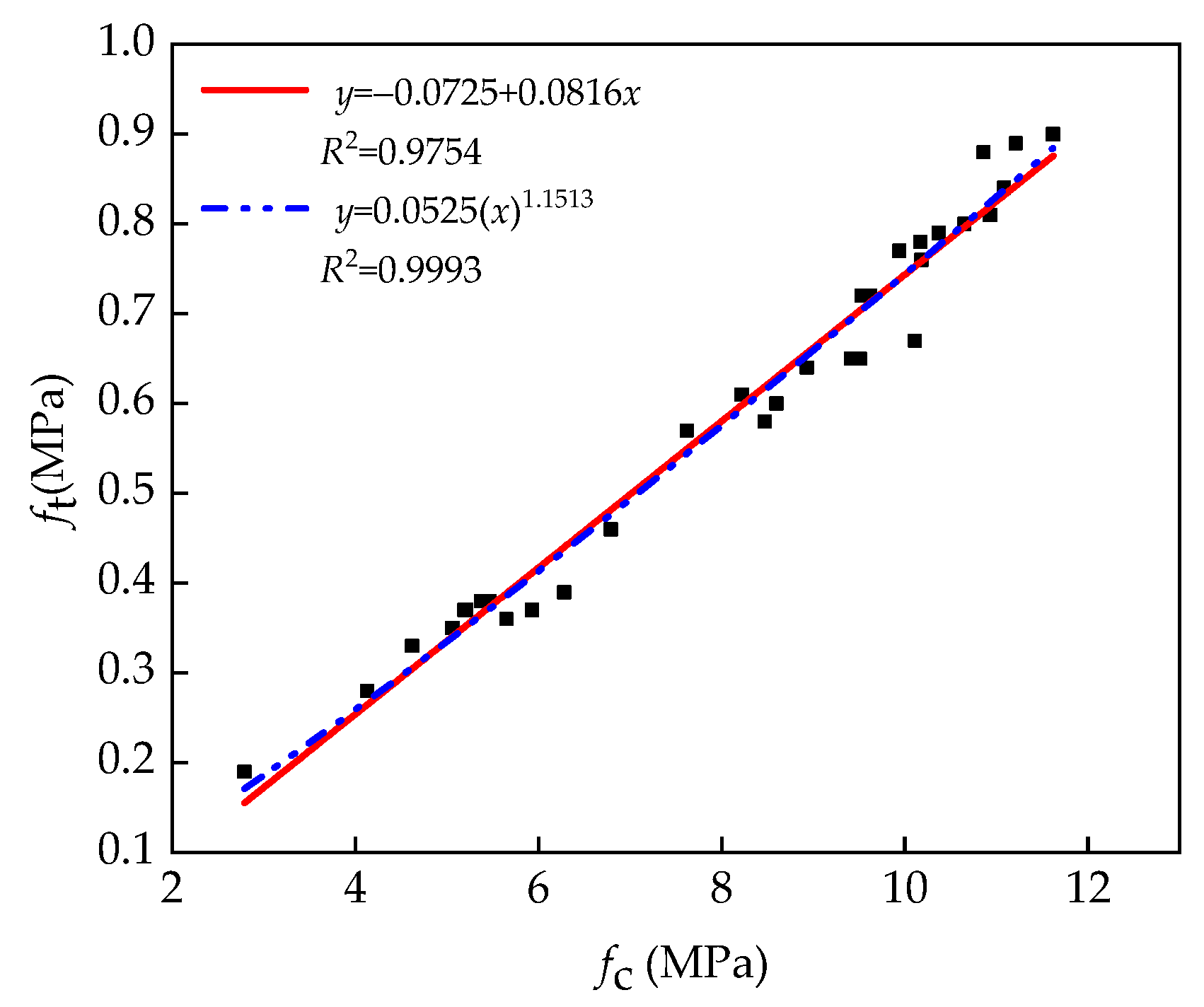
3.4. Relation between Unconfined Compressive Strength and Splitting Strength
3.5. Frost Resistance Test
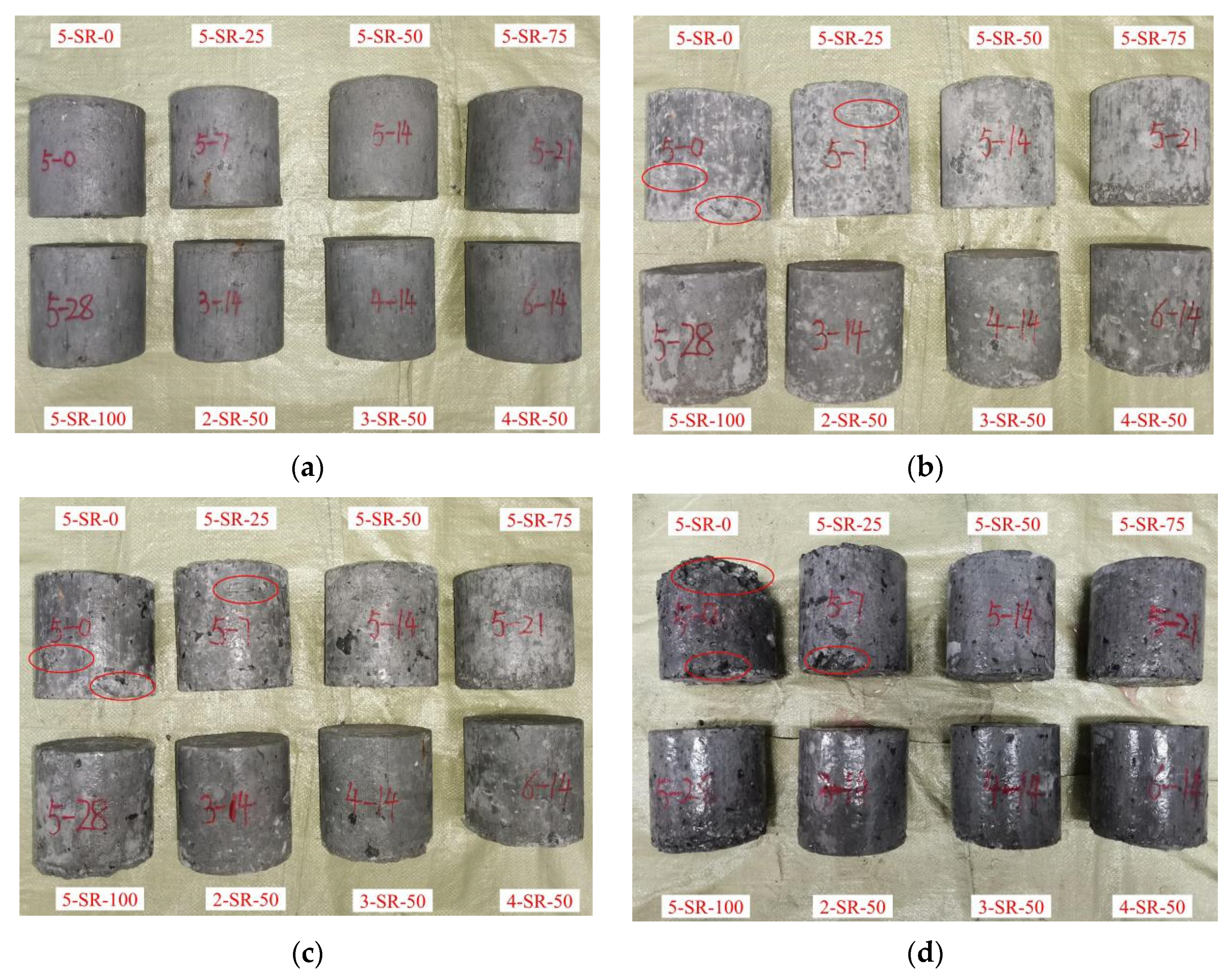
3.5.1. Appearance of the Specimens
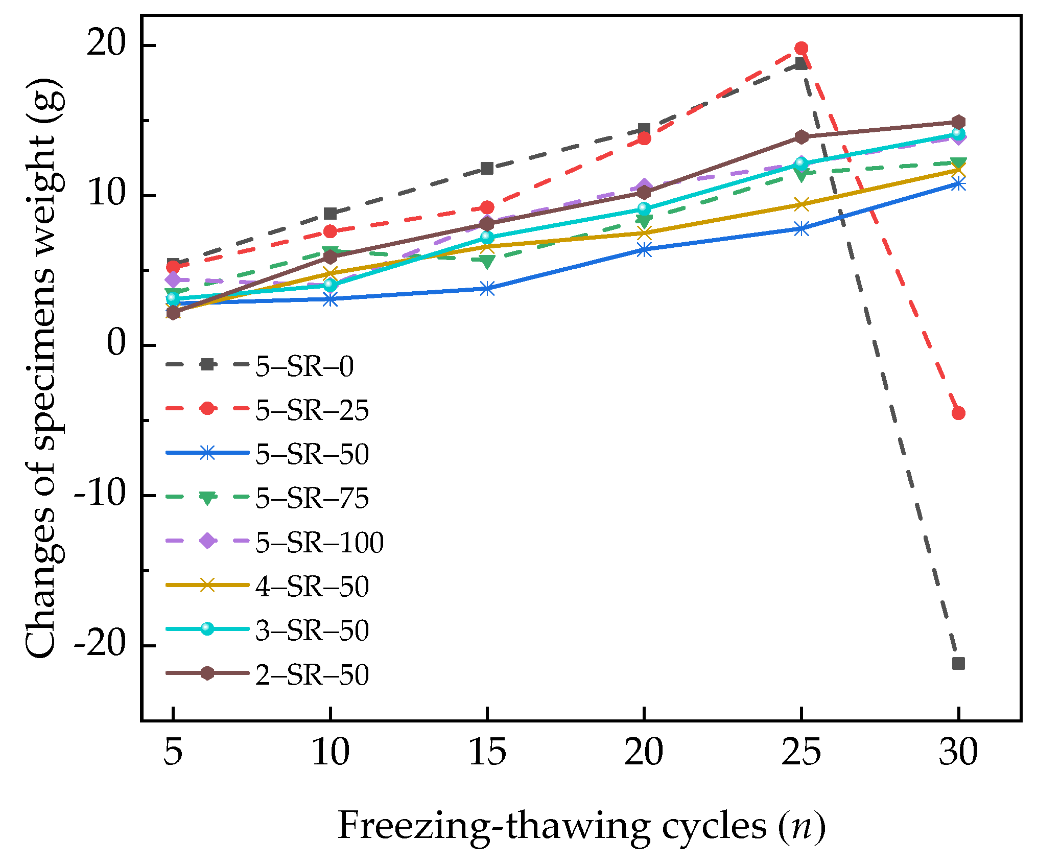
3.5.2. Change in the Weight of Specimens
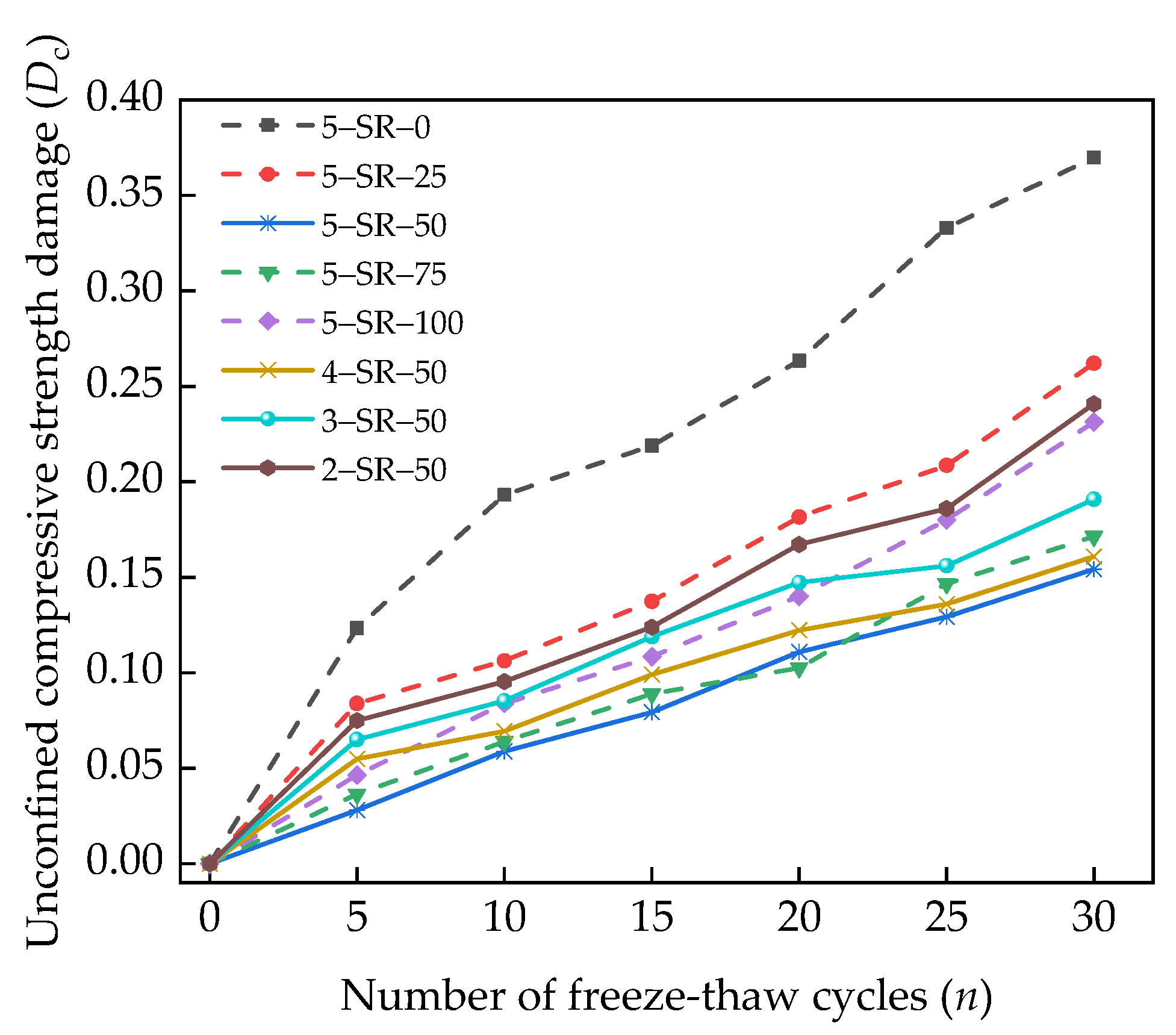
3.5.3. Loss Rate of Unconfined Compressive Strength
3.5.4. Analysis of Freeze–Thaw Failure Mechanism
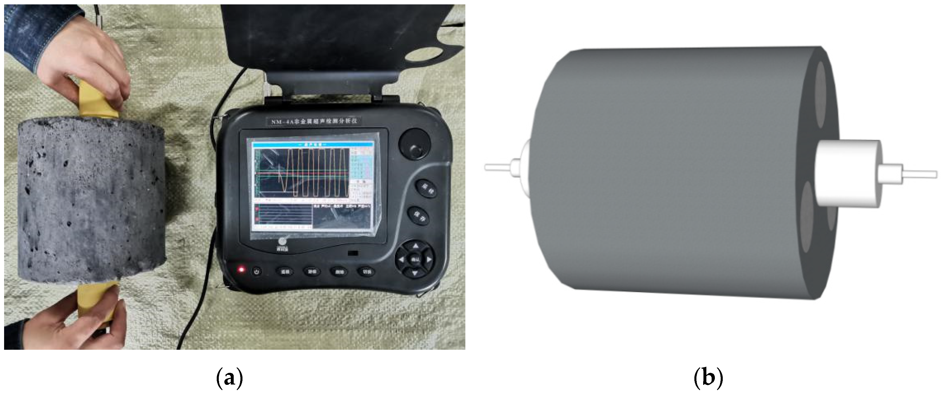
4. Ultrasonic Testing
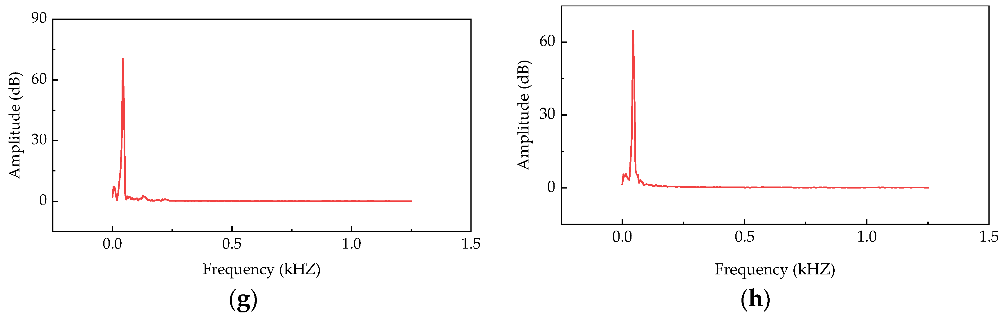
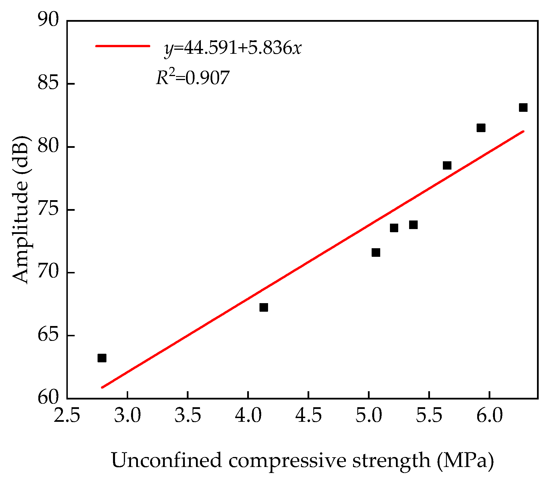
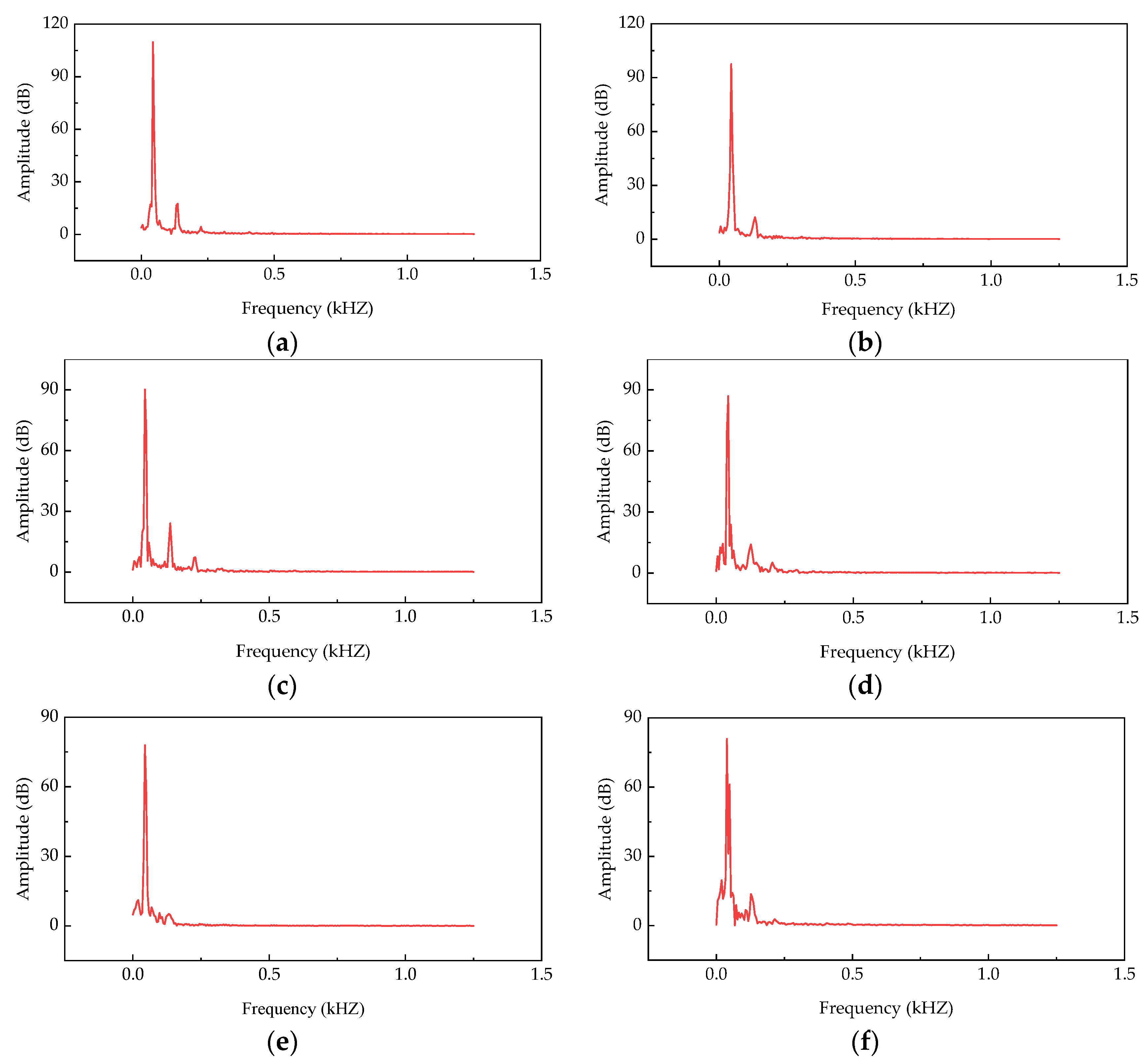
4.1. Relation between Ultrasonic Amplitude and Compressive Strength
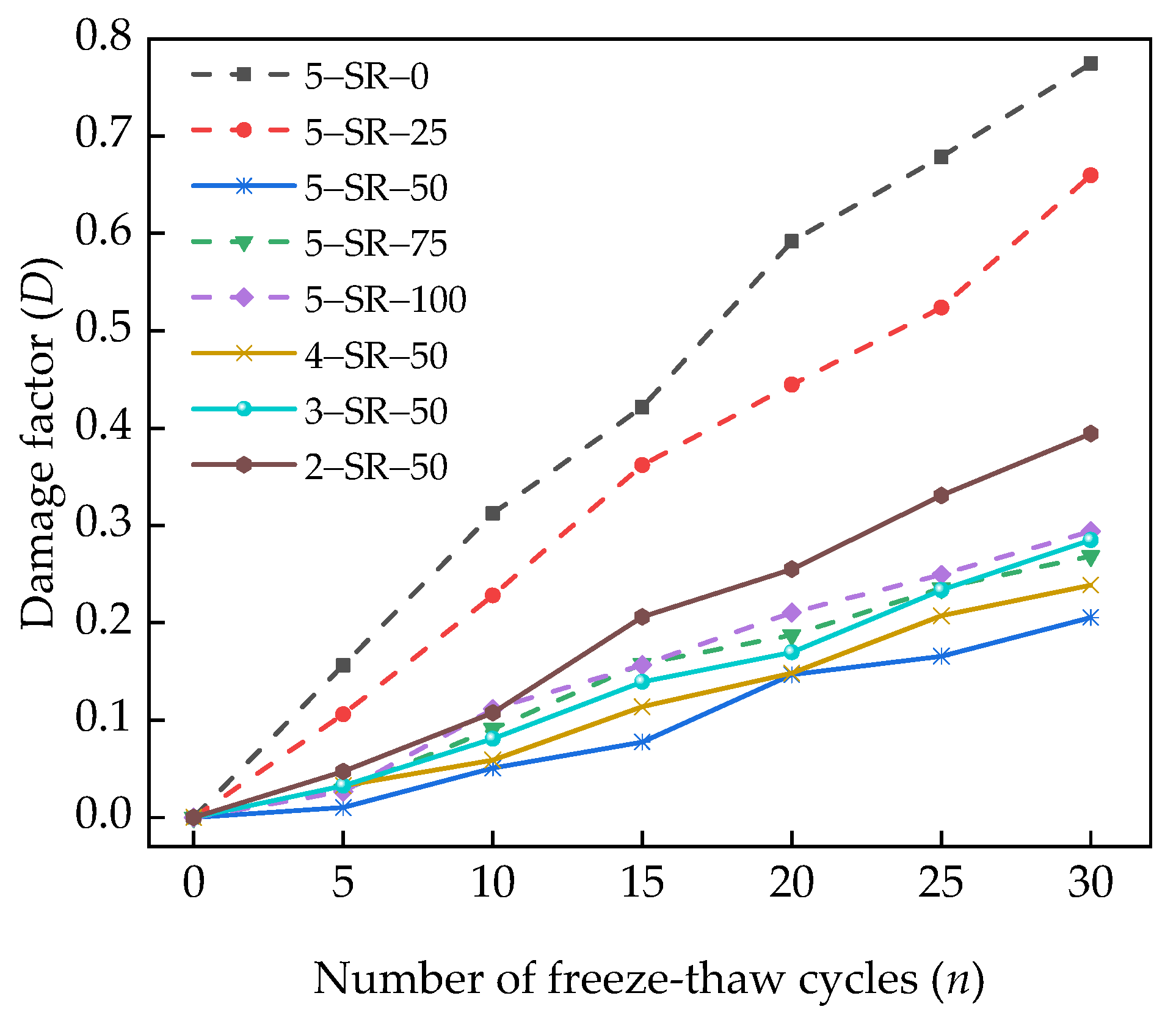
4.2. Relation between Ultrasonic Wave Velocity and Freeze–Thaw Cycles
4.3. Strength Degradation under Ultrasonic Testing
5. Discussion
- (1)
- Macadam of 0–4.75 mm was replaced by 0–4.75 mm slag, which not only reduced the consumption of macadam and the pollution of slag caused to the environment but also significantly increased the frost resistance of the mixture.
- (2)
- Based on the principles of ultrasonic testing, the relationship models between ultrasonic wave amplitude and unconfined compressive strength, freeze–thaw damage factor D, were established. According to the relationship models, ultrasonic nondestructive testing was used to detect the unconfined compressive strength and freeze–thaw damage degree of the mixture.
- (1)
- The fatigue and shrinkage performance of the mixture are not tested.
- (2)
- The meso-finite element model of mixture is not established.
- (3)
- A machine learning algorithm is not used to predict the strength and freeze–thaw damage degree of mixture.
6. Conclusions
- (1)
- The optimum water content of the specimens increases, and the maximum dry density decreases with an increase in the slag replacement rate. Slag has an adverse effect on the unconfined compressive strength of the specimens. However, with extension of the curing age, the adverse effect of slag on the unconfined compressive strength of the specimens decreases gradually. With an increase in the cement content, the unconfined compressive strength of the specimens increases.
- (2)
- The appearance of the specimens worsens, and the unconfined compressive strength decreases gradually with the increase of freeze–thaw cycles. The unconfined compressive strength loss of the specimens decreases at first and then increases with the increase of slag replacement rate, and the unconfined compressive strength loss decreases with the increase of cement content. When the cement content is 5% and the slag replacement rate is 50%, the unconfined compressive strength loss of the specimen is minimal.
- (3)
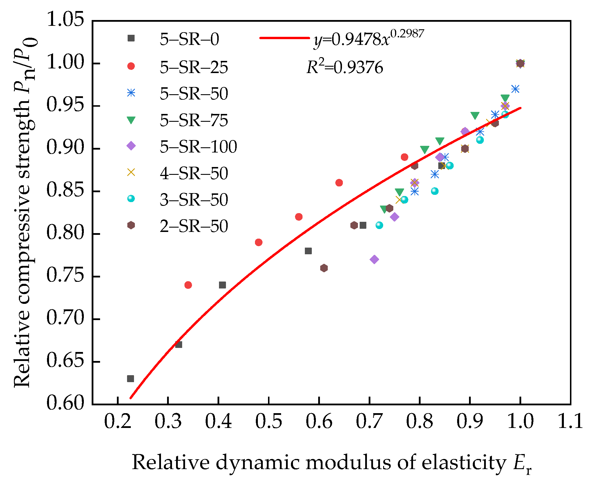
- According to the test results, the relationship model between compressive strength and splitting strength of the mixture was established by linear function and power function regression analyses. The relationship model between unconfined compressive strength at 7 days and ultrasonic amplitude was established. The formulas between ultrasonic wave velocity v, relative dynamic elastic modulus Er, and damage factor D were proposed. The strength attenuation model between relative dynamic elastic modulus and relative compressive strength under freeze–thaw cycles was established to evaluate the frost resistance of the mixture.
- (4)
- The comprehensive test results show that the slag replacement rate is recommended to be ~50%, and the mixture has good mechanical and frost resistance properties. When the cement content is 5%, the mixture can meet the technical requirements of expressway and first-class highway pavement base in China.
Author Contributions
Funding
Institutional Review Board Statement
Informed Consent Statement
Data Availability Statement
Conflicts of Interest
References
- Zhang, X.C.; Meng, Y.B. Brief analysis on present situation of comprehensive utilization of fly ash in China. Inorg. Chem. Ind. 2020, 52, 1–5. [Google Scholar]
- Ding, F.X.; Wang, W.; Liu, X.M.; Wang, L.; Sun, Y. Mechanical behavior of outer square inner circular concrete filled dual steel tubular stub columns. Steel Compos. Struct. 2021, 38, 305–317. [Google Scholar]
- Li, D.R.; Wang, W.J.; Ding, F.X.; Liu, X.M.; Fang, C.J. The impact of stirrups on the composite action of concrete-filled steel tubular stub columns under axial loading. Structures 2021, 30, 768–802. [Google Scholar]
- Ding, F.X.; Wang, W.J.; Liu, D.R. Study on the behavior of concrete-filled square double-skin steel tubular stub columns under axial loading. Structures 2020, 23, 665–676. [Google Scholar] [CrossRef]
- Golewski, G.L. The influence of microcrack width on the mechanical parameters in concrete with the addition of fly ash: Consideration of technological and ecological benefits. Constr. Build. Mater. 2019, 197, 849–861. [Google Scholar] [CrossRef]
- Poltue, T.; Suddeepong, A.; Horpibulsuk, S. Strength development of recycled concrete aggregate stabilized with fly ash-rice husk ash based geopolymer as pavement base material. Road Mater. Pavement. 2020, 21, 2344–2355. [Google Scholar] [CrossRef]
- Chu, H.H.; Khan, M.A.; Javed, M.; Zafar, A.; Khan, M.; Alabduljabbar, H.; Qayyum, S. Sustainable use of fly-ash: Use of gene-expression programming (GEP) and multi-expression programming (MEP) for forecasting the compressive strength geopolymer concrete. Ain Shams Eng. J. 2021, 12, 3603–3617. [Google Scholar] [CrossRef]
- Khan, M.A.; Memon, S.A.; Farooq, F.; Javed, M.F.; Alyousef, R. Compressive Strength of Fly-Ash-Based Geopolymer Concrete by Gene Expression Programming and Random Forest. Adv. Civ. Eng. 2021, 2021, 1–17. [Google Scholar] [CrossRef]
- Xiao, Q.Y.; Feng, S.J.; Sun, L.D. Mechanical properties and shrinkage properties of lime-fly ash stabilized semi-rigid recycled base. B. Chin. Ceram. Soc. 2019, 38, 3611–3618. [Google Scholar]
- Zhang, J.F.; Xu, J.W. Study on the strength and freezing resistance of lime and fly-ash and coal gangue mixture. Concrete 2017, 12, 92–94. [Google Scholar]
- Li, S.L.; Wu, W.L.; Wan, S. The study on properties of alkali-activated fly ash cement stabilized recycled aggregate. Highway Eng. 2020, 45, 197–202. [Google Scholar]
- Alireza, M.; Arulrajah, A.; Horpibulsuk, S. Effect of fly ash on properties of crushed brick and reclaimed asphalt in pavement base/subbase applications. J. Hazard. Mater. 2017, 321, 547–556. [Google Scholar]
- Thi, N.N.; Truong, S.B.; Do, N. Reusing coal ash of thermal power plant in a pavement base course. J. King Saud Univ.-Eng. Sci. 2020, 2020, 20. [Google Scholar]
- Zhu, Y.T.; Zhao, Y.; Zhao, C. Experimental study on environmental safety of cement stabilized MSWI-BA macadam base. B. Chin. Ceram. Soc. 2018, 37, 3296–3302. [Google Scholar]
- Liu, D.; Li, L.H.; Cui, H.J. Pavement performance of cement stabilized municipal solid waste incineration bottom ash aggregate and crushed stones. J. TONGJI Univ. Nat. Sci. Ed. 2015, 43, 405–409. [Google Scholar]
- Xue, G.Q.; Lu, C.; Gu, H.D. Experimental and numerical analysis of municipal solid waste incineration bottom ash used in road base. Sci. Techno. Eng. 2018, 18, 148–155. [Google Scholar]
- Zhang, X.D.; Ren, K. Strength and damage characteristic of cement stabilized cinder macadam base. J. Traffic Transport. Eng. 2018, 18, 1–9. [Google Scholar]
- Jia, L.; Zhang, L.; Guo, J. Evaluation on strength properties of lime-slag stabilized loess as pavement base material. Sustainability 2019, 11, 4099. [Google Scholar] [CrossRef] [Green Version]
- Du, Y.; Wei, M.; Reddy, K.R. Effect of acid rain pH on leaching behavior of cement stabilized lead-contaminated soil. J. Hazard. Mater. 2014, 271, 131–140. [Google Scholar] [CrossRef]
- Brue, F.; Davy, C.A.; Skoczylas, F. Effect of temperature on the water retention properties of two high performance concretes. Cem. Concr. Res. 2012, 42, 384–396. [Google Scholar] [CrossRef]
- Jiang, J.H.; Yuan, Y.S. Relationship of moisture content with temperature and relative humidity in concrete. Mag. Concr. Res. 2013, 65, 685–692. [Google Scholar] [CrossRef]
- CJJ1-2008. In Code for Construction and Quality Acceptance of Road Works in City and Town; China Architecture & Building Press: Beijing, China, 2008.
- JTG E51-2009. In Test Methods of Materials Stabilized with Inorganic Binders for Highway Engineering; Ministry of Transport of the People’s Republic of China: Beijing, China, 2009.
- Li, H.B.; Yin, J.G.; Yan, P.F.; Sun, H. Experimental investigation on the mechanical properties of self-compacting concrete under uniaxial and triaxial stress. Materials 2020, 13, 1830. [Google Scholar] [CrossRef]
- Sun, H.; Xu, Q.Y.; Yan, P.F.; Yin, J.G.; Lou, P. A Study on Axial Compression Performance of Concrete-Filled Steel-Tubular Shear Wall with a Multi-Cavity T-Shaped Cross-Section. Energies 2020, 13, 4831. [Google Scholar] [CrossRef]
- JTG/T F20-2015. In Technical Guidelines for Construction of Highway Roadbases; Ministry of Transport of the People’s Republic of China: Beijing, China, 2015.
- Ding, S.; Niu, D.T.; Wang, J.B. Experimental study on micro-structure and mechanical properties of shotcrete with fly ash. B. Chin. Ceram. Soc. 2015, 34, 1187–1192. [Google Scholar]
- Li, H.; Wang, J.B.; Guo, Q.J. Mechanical properties of recycled aggregate concrete with mineral admixture. B. Chin. Ceram. Soc. 2020, 39, 2608–2614. [Google Scholar]
- Guo, Z.G.; Jiang, T.; Zhang, J. Mechanical and durability properties of sustainable self-compacting concrete with recycled concrete aggregate and fly ash, slag and silica fume. Constr. Build. Mater. 2020, 231, 849–861. [Google Scholar] [CrossRef]
- Cheng, M.; Zhang, J.S.; Duan, L.X. Experimental study on mechanical properties of concrete reinforced with hybrid fiber and fly ash subjected to freeze-thaw cycles. Sci. Technol. Eng. 2020, 20, 11288–11294. [Google Scholar]
- Wang, J.B.; Niu, D.T.; Yuan, B. Constitutive relation and microstructure on shotcrete after freeze and thaw damage. J. Civ. Archit. Environ. Eng. 2016, 38, 30–39. [Google Scholar]
- Liu, Y.P.; Niu, D.T.; Wang, J.B. Study on durability of sprayed concrete under the action of freeze-thaw cycle. B. Chin. Ceram. Soc. 2014, 33, 2381–2386. [Google Scholar]
- Li, H.B.; Yan, P.F.; Sun, H. Axial compression performance and ultrasonic testing of multicavity concrete-filled steel tube shear wall under axial load. Adv. Civ. Eng. 2020, 2020, 1–19. [Google Scholar] [CrossRef]
- Li, H.; Guo, Q.B.; Wang, J.B. Meso-/micro-structure of interfacial transition zone and durability of recycled aggregate concrete: A review. Mater. Rev. 2020, 34, 13050–13057. [Google Scholar]
- Wang, J.B.; Niu, D.T.; Liu, Y.P. Investigation of frost resistance and stress-strain curve of shotcrete. J. Funct. Mater. 2015, 46, 6095–6101. [Google Scholar]
- Su, X.P.; Wang, Q.; Wang, W.H. Frost resistance and durability mechanism of concrete under saline-alkali condition in seasonal frozen soil area. J. Jilin Univ. 2014, 44, 1244–1253. [Google Scholar]
- Zhao, Y.R.; Fan, X.Q.; Wang, L.Q. Attenuation model of mechanical properties of concrete under different freezing and thawing. Acta Mater. Compos. Sin. 2017, 34, 463–470. [Google Scholar]


| Composition | SiO2 | Al2O3 | Fe2O3 | CaO | MgO | K2O | Na2O | TiO2 | SO3 | LOI |
|---|---|---|---|---|---|---|---|---|---|---|
| Slag (%) | 47.47 | 22.69 | 8.77 | 8.57 | 1.84 | 2.23 | 1.09 | 1.56 | 1.21 | 4.52 |
| Fly ash (%) | 45.16 | 32.91 | 7.47 | 4.95 | 1.20 | 2.12 | 0.78 | 1.77 | 0.80 | 2.63 |
| Cement (%) | 22.12 | 7.42 | 5.33 | 56.85 | 1.53 | 0.76 | 0.33 | 0.11 | 2.87 | 1.52 |
| Material | Particle Size (mm) | Crushing Value (%) | Apparent Density (g·cm−3) | Packing Density (g·cm−3) | Water Absorption Rate (%) |
|---|---|---|---|---|---|
| Slag | 0–2.36 | / | 2.353 | 0.786 | 11.1 |
| 2.36–4.75 | 38.4 | 2.414 | 0.758 | ||
| Macadam | 0–2.36 | / | 2.578 | 1.534 | 0.68 |
| 2.36–4.75 | 16.7 | 2.622 | 1.507 | ||
| 4.75–9.5 | 18.8 | 2.679 | 1.432 | 0.64 | |
| 9.5–16 | 20.9 | 2.694 | 1.505 | 0.56 | |
| 16–26.5 | 21.5 | 2.705 | 1.536 | 0.51 |
| Setting Time (min) | Flexural Strength (MPa) | Compressive Strength (MPa) | Fineness (%) | |||
|---|---|---|---|---|---|---|
| Initial Setting | Final Setting | 3 Days | 28 Days | 3 Days | 28 Days | |
| 225 | 375 | 5.61 | 8.72 | 25.50 | 42.65 | 1.63 |
| Mixture Number | Mass Fraction of Materials (%) | ||||||
|---|---|---|---|---|---|---|---|
| Gradation of Macadam (mm) | Slag (mm) | Fly Ash | Cement | ||||
| 16–26.5 | 9.5–16 | 4.75–9.5 | 0–4.75 | 0–4.75 | |||
| 5-SR-0 | 18 | 19 | 15 | 28 | 0 | 15 | 5 |
| 5-SR-25 | 18 | 19 | 15 | 21 | 7 | 15 | 5 |
| 5-SR-50 | 18 | 19 | 15 | 14 | 14 | 15 | 5 |
| 5-SR-75 | 18 | 19 | 15 | 7 | 21 | 15 | 5 |
| 5-SR-100 | 18 | 19 | 15 | 0 | 28 | 15 | 5 |
| 4-SR-y | 18 | 19 | 16 | 28-x | x | 15 | 4 |
| 3-SR-y | 18 | 19 | 17 | 28-x | x | 15 | 3 |
| 2-SR-y | 18 | 19 | 18 | 28-x | x | 15 | 2 |
| Mixture Number | Optimum Moisture Content (%) | Maximum Dry Density (g·cm−3) |
|---|---|---|
| 5-SR-0 | 8.3 | 2.022 |
| 5-SR-25 | 9.3 | 1.970 |
| 5-SR-50 | 10.5 | 1.915 |
| 5-SR-75 | 11.8 | 1.858 |
| 5-SR-100 | 13.4 | 1.809 |
| Mixture Number | Maximum Value (MPa) | Minimum Value (MPa) | Average Value (MPa) | Standard Deviation (%) | Variation Coefficient (%) | Representative Value of 95% (MPa) |
|---|---|---|---|---|---|---|
| 5-SR-0 | 6.71 | 5.97 | 6.28 | 38.47 | 6.13 | 5.65 |
| 5-SR-25 | 6.13 | 5.63 | 5.93 | 26.57 | 4.48 | 5.49 |
| 5-SR-50 | 5.93 | 5.29 | 5.65 | 32.40 | 5.74 | 5.11 |
| 5-SR-75 | 5.78 | 5.05 | 5.37 | 39.03 | 7.28 | 4.72 |
| 5-SR-100 | 5.35 | 4.71 | 5.06 | 32.27 | 6.38 | 4.53 |
| 4-SR-50 | 5.75 | 4.71 | 5.21 | 51.98 | 9.97 | 4.36 |
| 3-SR-50 | 4.44 | 3.86 | 4.13 | 29.41 | 7.13 | 3.64 |
| 2-SR-50 | 3.01 | 2.63 | 2.79 | 20.12 | 7.21 | 2.46 |
| Mixture Number | Measured Distance | Sound Time | Wave Velocity |
|---|---|---|---|
| l (mm) | t (μs) | v (m/s) | |
| 5-SR-0 | 151.6 | 39.8 | 3806.7 |
| 5-SR-25 | 151.8 | 41.5 | 3661.1 |
| 5-SR-50 | 151.3 | 41.9 | 3614.4 |
| 5-SR-75 | 150.9 | 44.0 | 3427.7 |
| 5-SR-100 | 151.5 | 45.1 | 3362.7 |
| 4-SR-50 | 151.2 | 43.1 | 3508.1 |
| 3-SR-50 | 151.3 | 46.9 | 3223.3 |
| 2-SR-50 | 151.7 | 52.6 | 2883.1 |
Publisher’s Note: MDPI stays neutral with regard to jurisdictional claims in published maps and institutional affiliations. |
© 2021 by the authors. Licensee MDPI, Basel, Switzerland. This article is an open access article distributed under the terms and conditions of the Creative Commons Attribution (CC BY) license (https://creativecommons.org/licenses/by/4.0/).
Share and Cite
Li, H.; Yan, P.; Tian, J.; Sun, H.; Yin, J. Study on Mechanical and Frost Resistance Properties of Slag and Macadam Stabilized with Cement and Fly Ash. Materials 2021, 14, 7241. https://doi.org/10.3390/ma14237241
Li H, Yan P, Tian J, Sun H, Yin J. Study on Mechanical and Frost Resistance Properties of Slag and Macadam Stabilized with Cement and Fly Ash. Materials. 2021; 14(23):7241. https://doi.org/10.3390/ma14237241
Chicago/Turabian StyleLi, Hongbo, Pengfei Yan, Juncang Tian, Hao Sun, and Jianguang Yin. 2021. "Study on Mechanical and Frost Resistance Properties of Slag and Macadam Stabilized with Cement and Fly Ash" Materials 14, no. 23: 7241. https://doi.org/10.3390/ma14237241
APA StyleLi, H., Yan, P., Tian, J., Sun, H., & Yin, J. (2021). Study on Mechanical and Frost Resistance Properties of Slag and Macadam Stabilized with Cement and Fly Ash. Materials, 14(23), 7241. https://doi.org/10.3390/ma14237241