
Wire Laser Metal Deposition Additive Manufacturing of Duplex Stainless Steel Components—Development of a Systematic Methodology

 , , ,
, , ,
Abstract
:1. Introduction
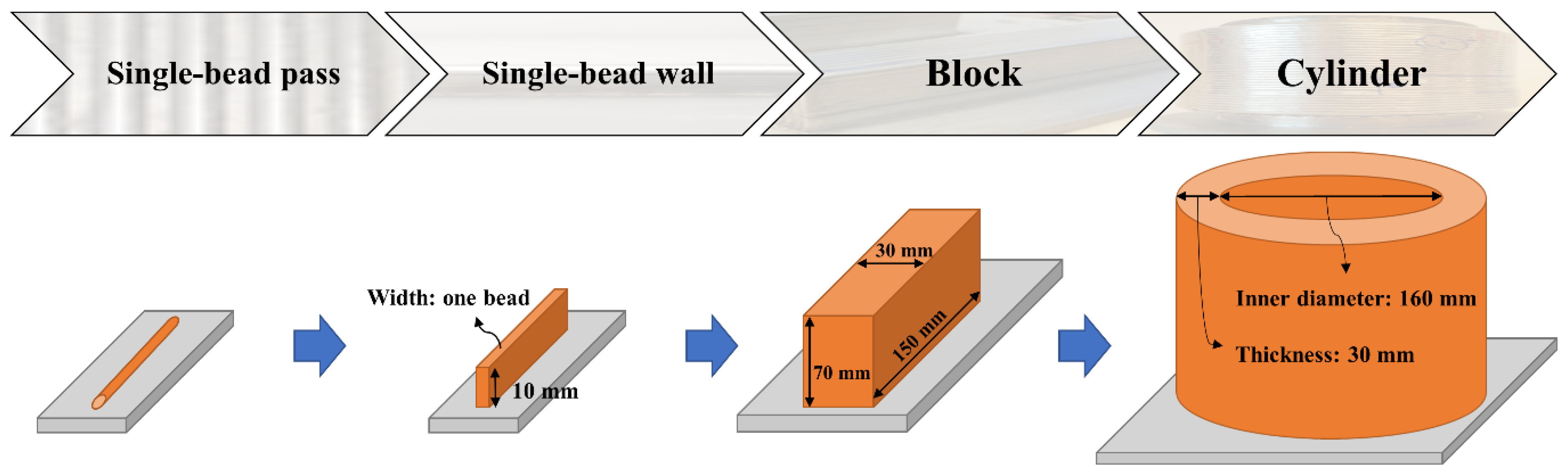
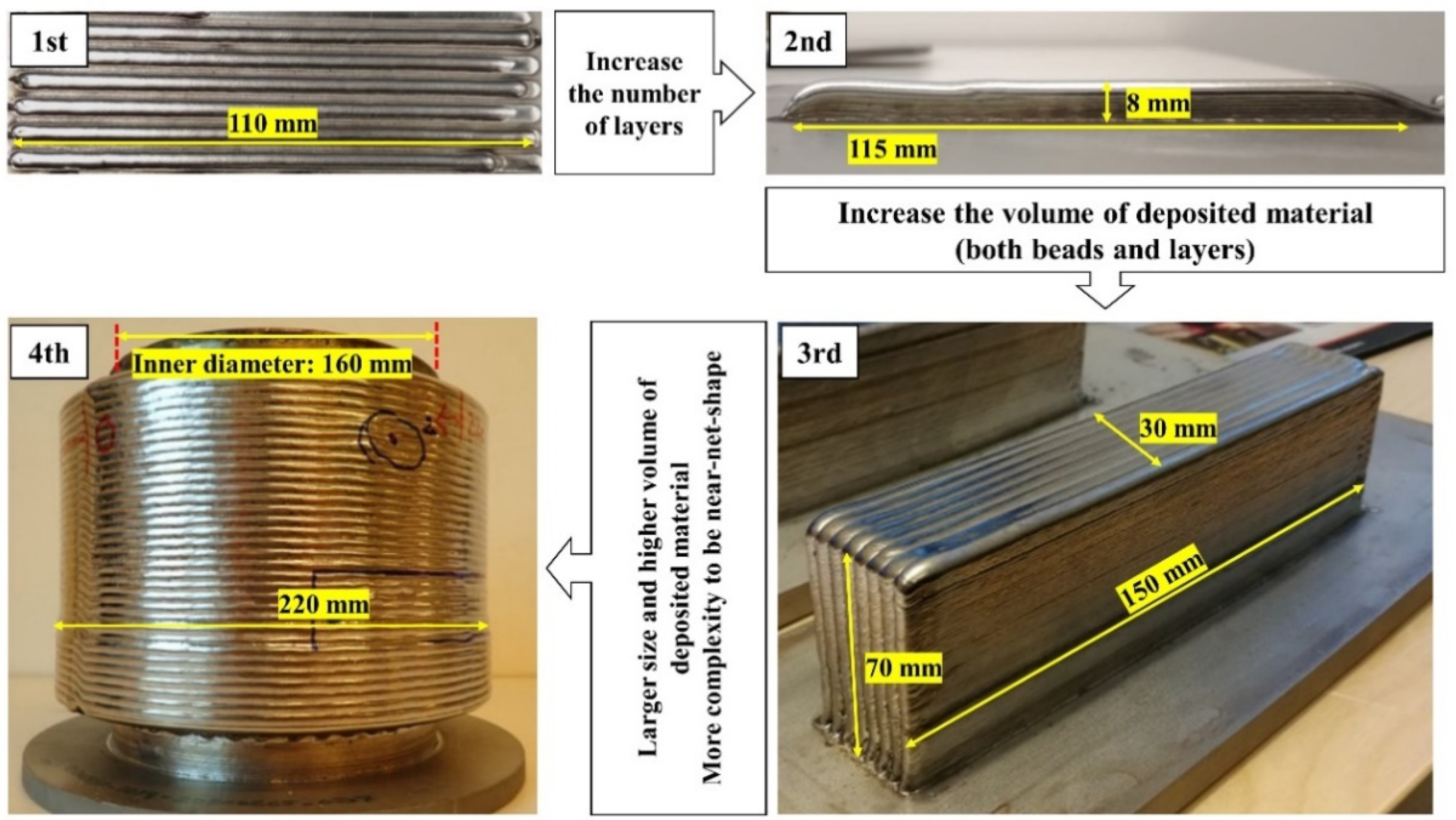
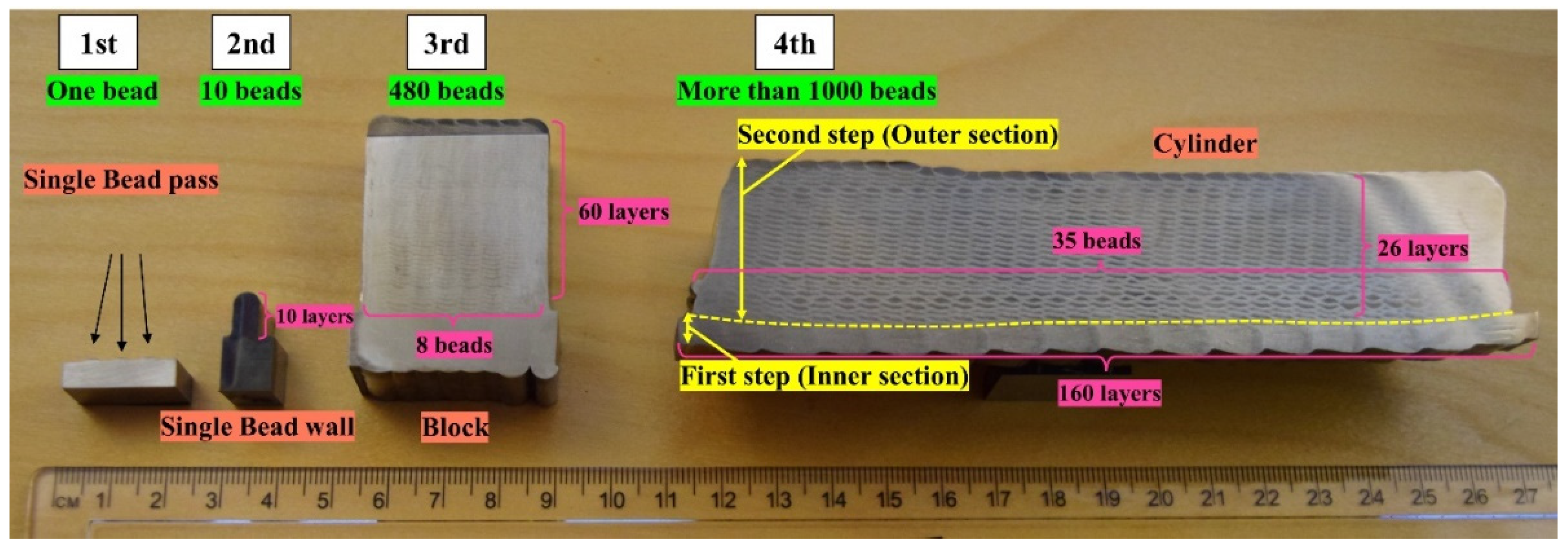
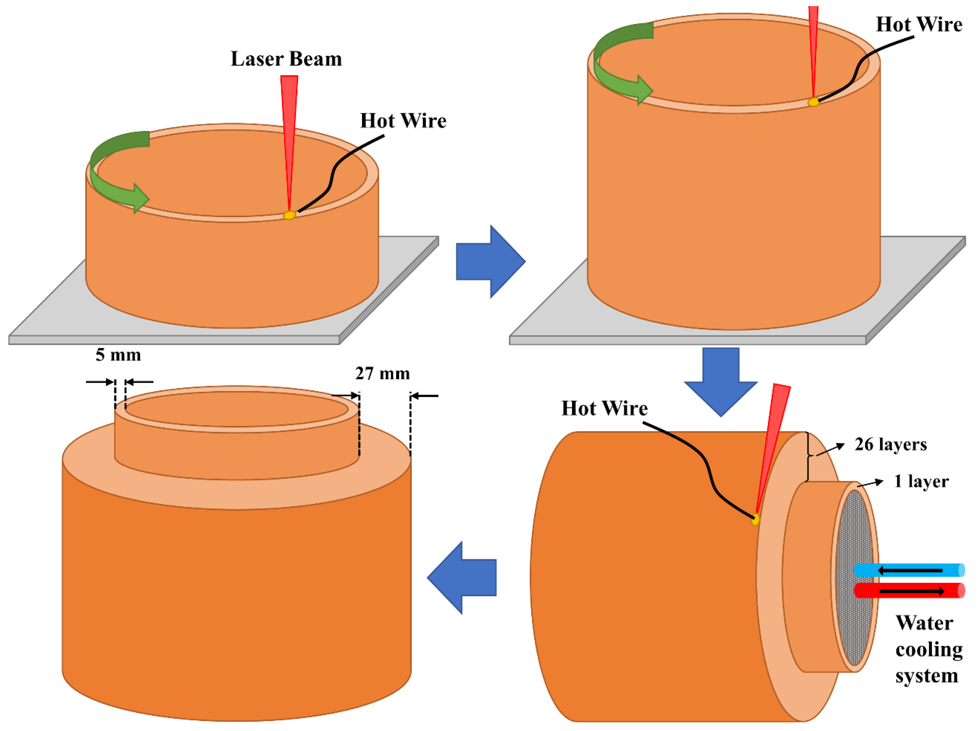
2. The Systematic Four-Stage Methodology
3. Experimental
3.1. Materials
3.2. Laser Metal Deposition with Wire Setup
3.3. Heat Treatment
3.4. Testing and Characterization
4. Results
4.1. Material Produced by the Four-Stage Methodology
4.2. Microstructure
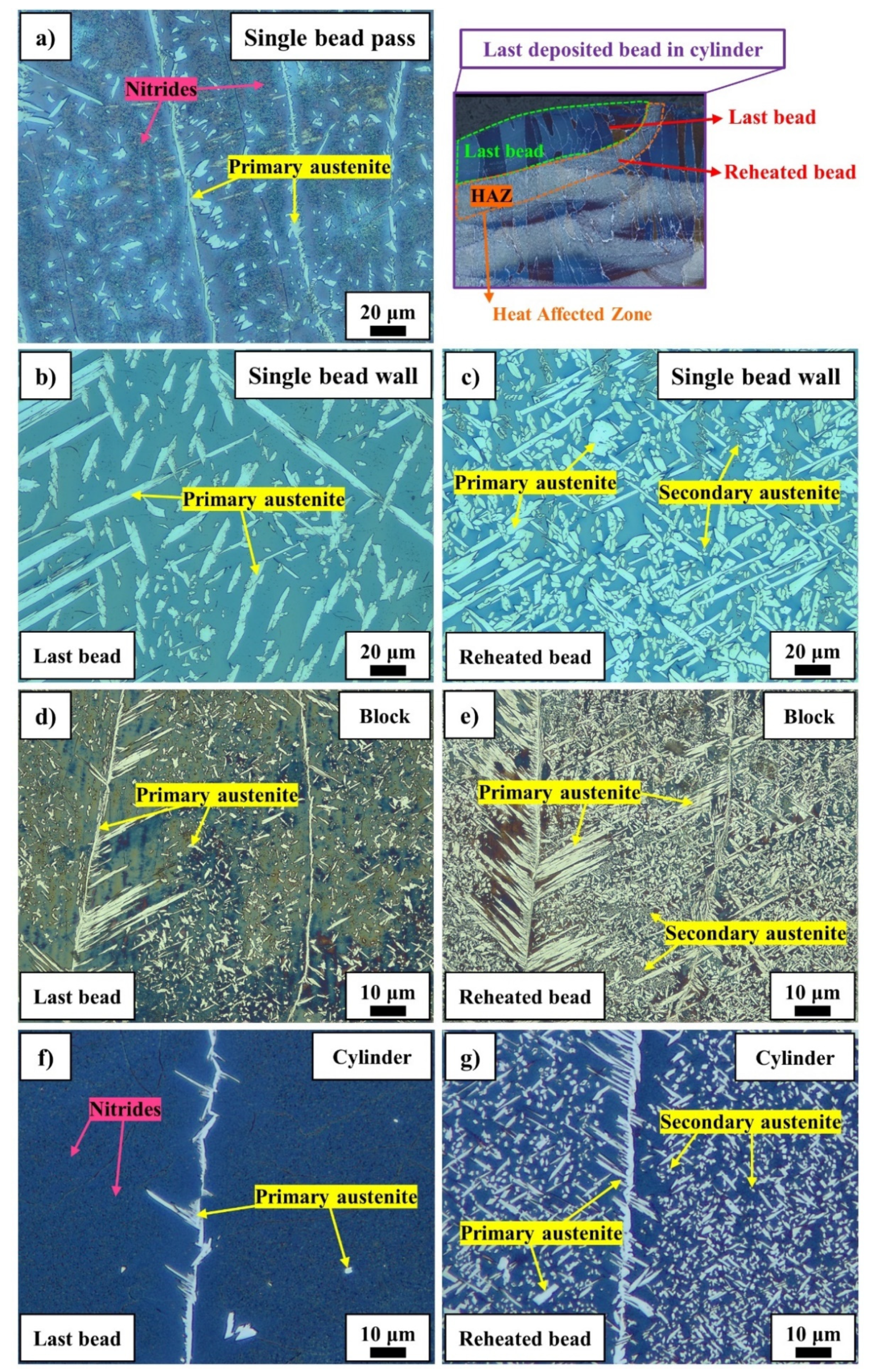
4.2.1. Last Bead and Reheated Bead Microstructures
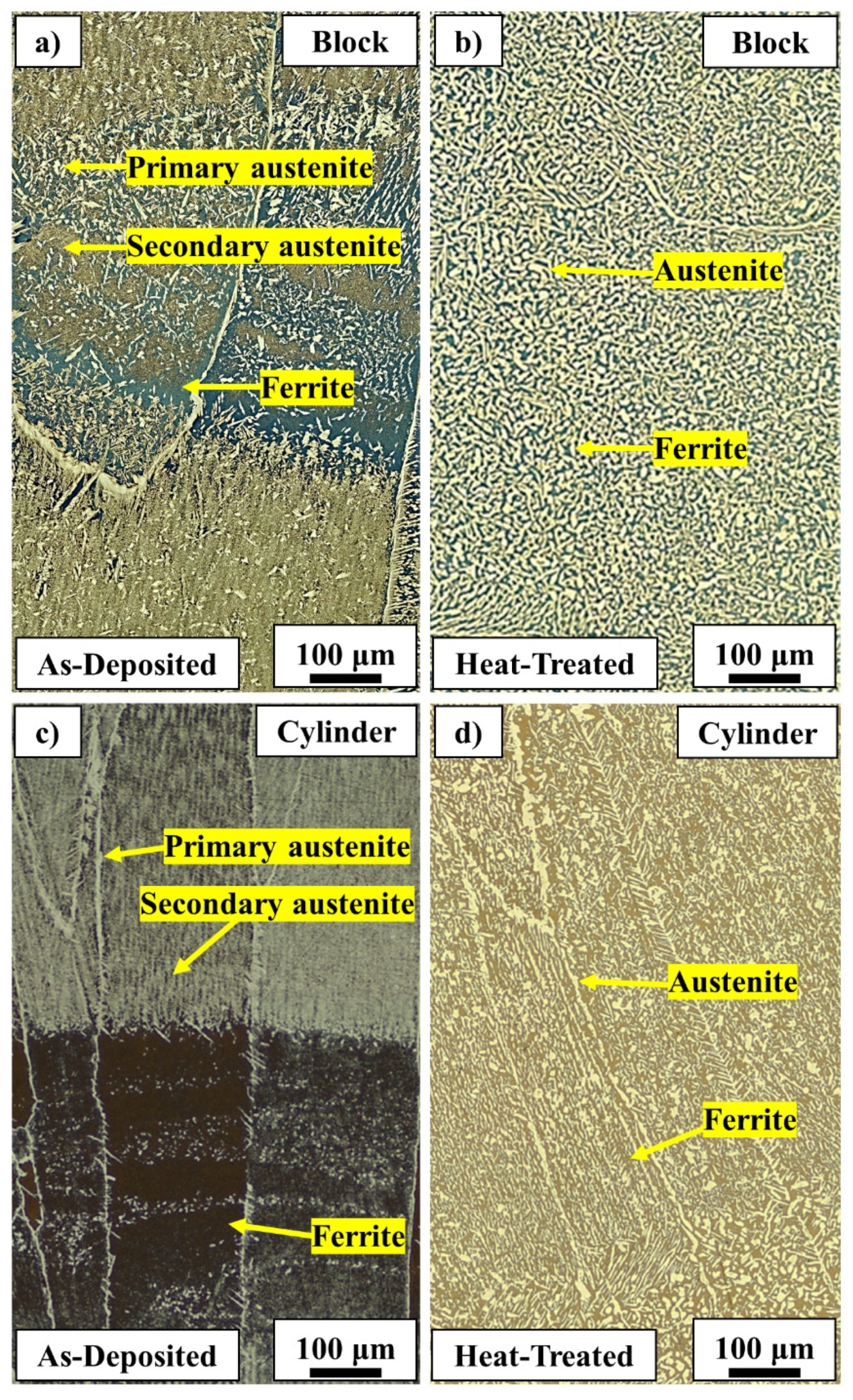
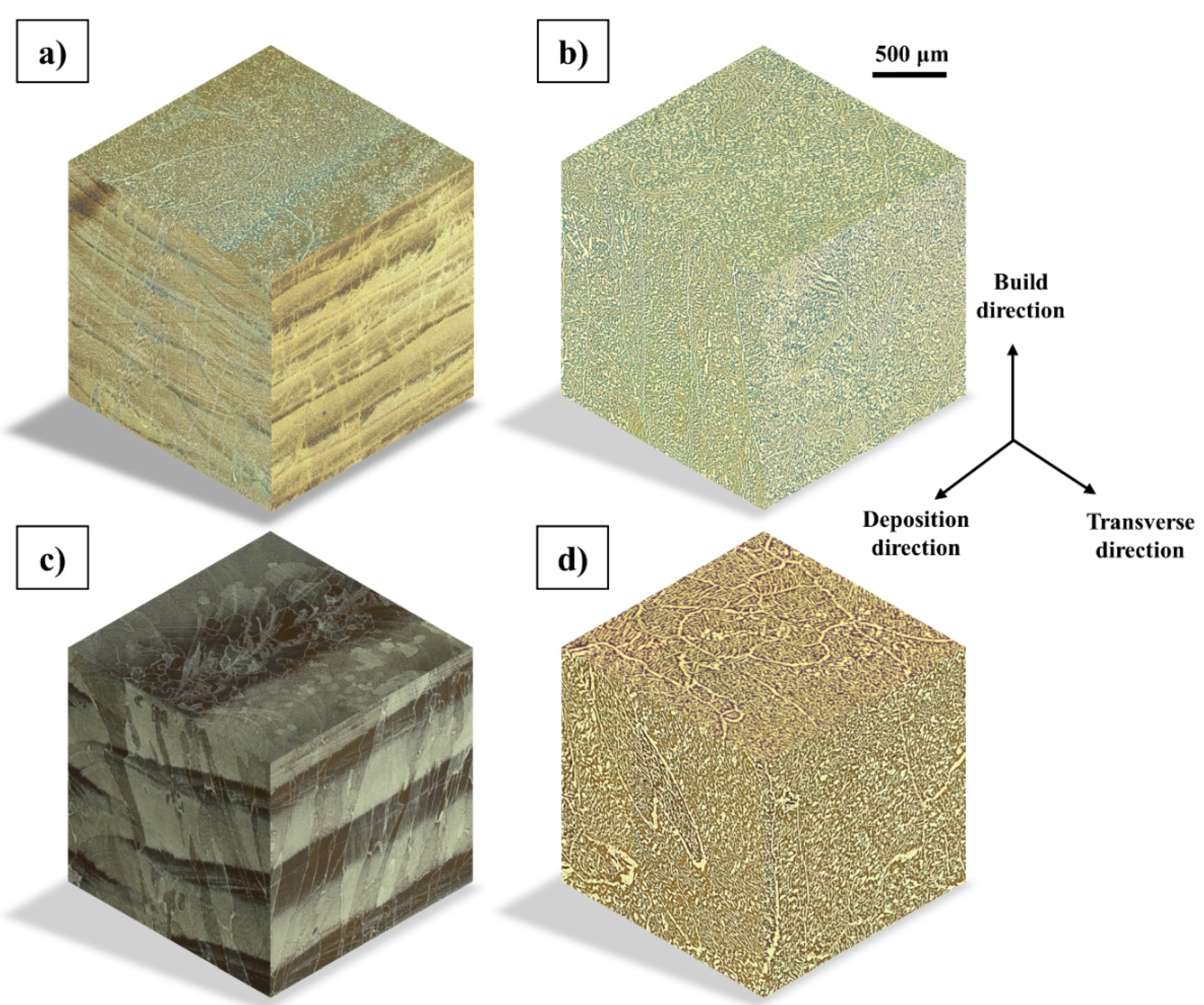
4.2.2. As-Deposited and Heat-Treated Bulk Microstructures
4.3. Chemical Analysis
4.4. Mechanical Properties
4.5. Thermodynamic Calculations
5. Discussion
5.1. Deposit Quality
5.2. Nitrogen Loss
5.3. Microstructure
5.3.1. As-Deposited
5.3.2. Heat-Treated
5.4. Mechanical Properties
5.5. Additive Manufacturing of Duplex Stainless Steel Components
5.6. Four-Stage Methodology
6. Conclusions
- The implementation of the four-stage methodology made it possible to achieve a stable and consistent LMDw process while, step by step, the volume of deposited material and the complexity of the additively manufactured components increased.
- Addition of water cooling was found necessary to avoid heat accumulation when increasing component size.
- The final components were of high quality with no cracks or lack of fusion defects, and only a few small pores were detected.
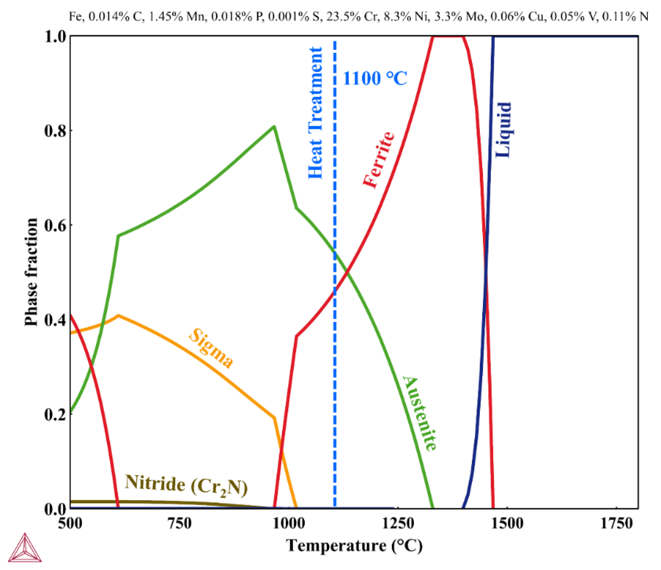
- Some nitrogen loss was observed resulting in a content of 0.11% N in the cylinder compared to 0.14% N in the wire.
- The as-deposited duplex microstructure was inhomogeneous and repetitive and included regions with low and high fractions of austenite. Nitrides were observed in highly ferritic regions.
- Heat treatment at 1100 °C for 1 h locally and globally homogenized the microstructure, removed nitrides, and balanced the ferrite and austenite fractions. The austenite fractions reached around 50% after heat treatment.
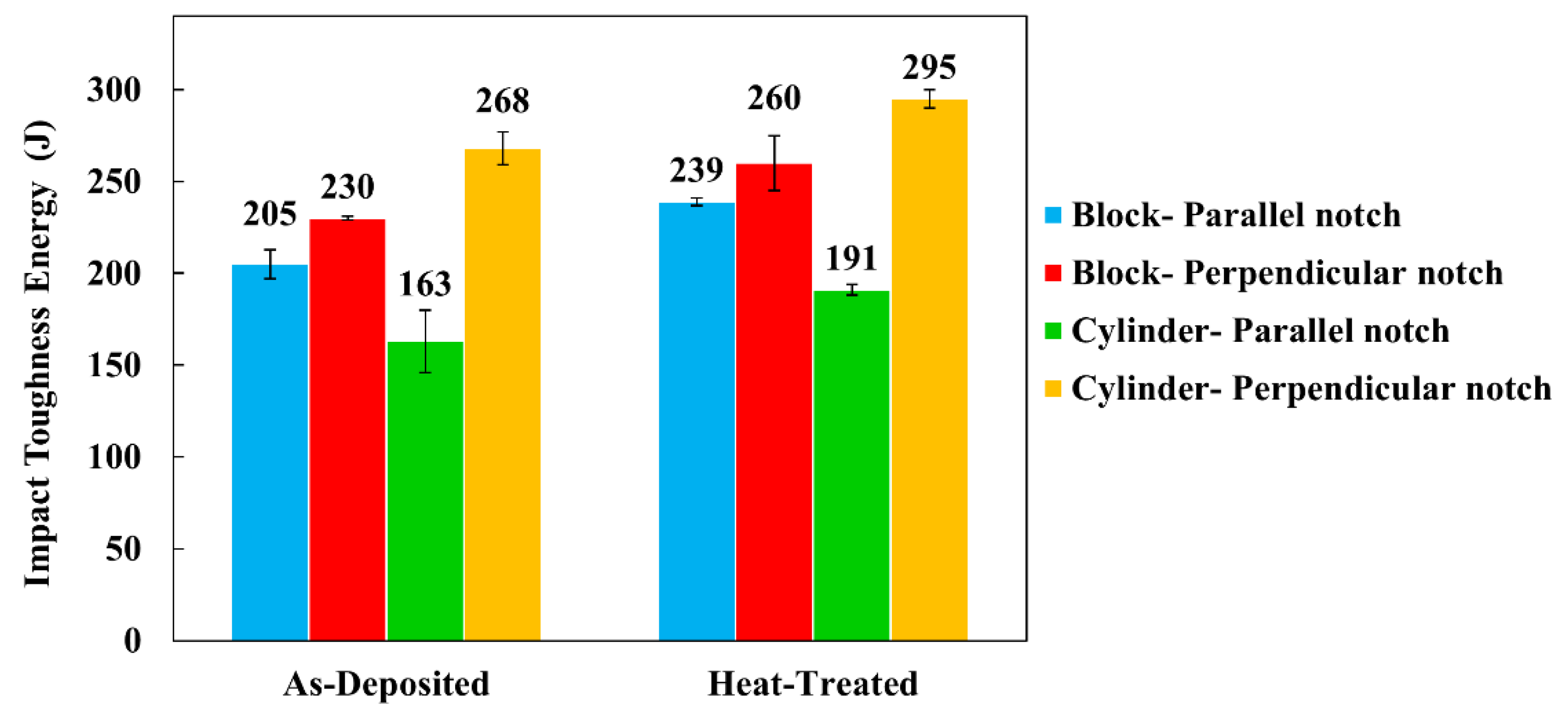
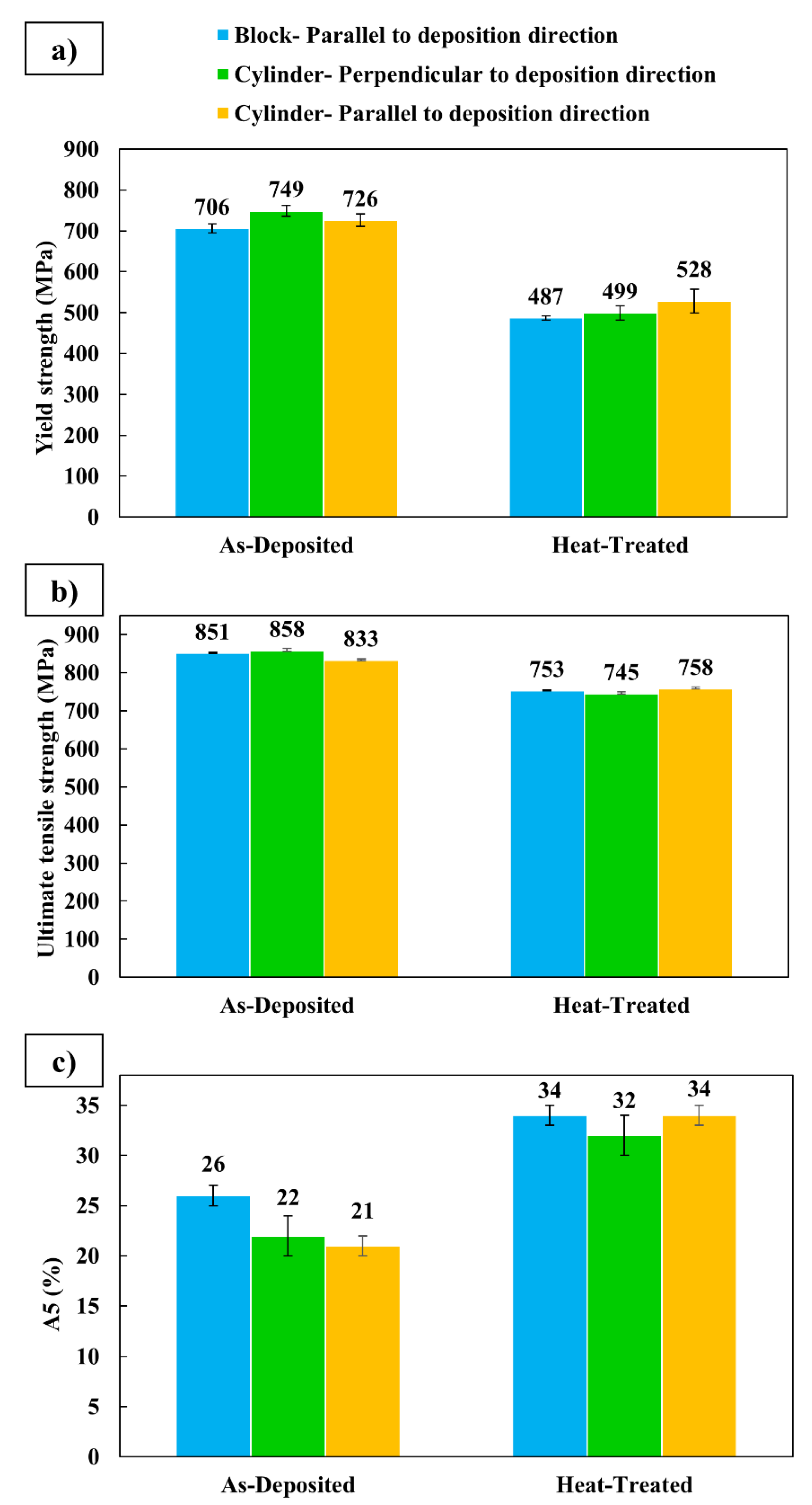
- Strength and toughness were at a high level, comparable to those of the corresponding steel grade, both as-deposited and after heat treatment. The highest strength was achieved in as-deposited condition with an average yield strength of 749 MPa and average UTS of 858 MPa, and the best toughness and ductility was in the heat-treated condition by an average of 34%. The heat treatment increased the toughness and ductility, while it decreased the strength.
Author Contributions
Funding
Institutional Review Board Statement
Informed Consent Statement
Data Availability Statement
Conflicts of Interest
References
- Haghdadi, N.; Laleh, M.; Moyle, M.; Primig, S. Additive manufacturing of steels: A review of achievements and challenges. J. Mater. Sci. 2021, 56, 64–107. [Google Scholar] [CrossRef]
- ASTM. Standard Terminology for Additive Manufacturing Technologies; F2792-12a; ASTM International: West Conshohocken, PA, USA, 2012; Volume 63, pp. 4–11. [Google Scholar]
- Kisielewicz, A.; Thalavai Pandian, K.; Sthen, D.; Hagqvist, P.; Valiente Bermejo, M.A.; Sikström, F.; Ancona, A. Hot-Wire Laser-Directed Energy Deposition: Process Characteristics and Benefits of Resistive Pre-Heating of the Feedstock Wire. Metals 2021, 11, 634. [Google Scholar] [CrossRef]
- Valiente Bermejo, M.A.; Thalavai Pandian, K.; Axelsson, B.; Harati, E.; Kisielewicz, A.; Karlsson, L. Microstructure of laser metal deposited duplex stainless steel: Influence of shielding gas and heat treatment. Weld. World 2021, 65, 525–541. [Google Scholar] [CrossRef]
- Shaikh, M.O.; Chen, C.C.; Chiang, H.C.; Chen, J.R.; Chou, Y.C.; Kuo, T.Y.; Ameyama, K.; Chuang, C.H. Additive manufacturing using fine wire-based laser metal deposition. Rapid Prototyp. J. 2020, 26, 473–483. [Google Scholar] [CrossRef]
- Kulkarni, J.D.; Goka, S.B.; Parchuri, P.K.; Yamamoto, H.; Ito, K.; Simhambhatla, S. Microstructure evolution along build direction for thin-wall components fabricated with wire-direct energy deposition. Rapid Prototyp. J. 2021, 27, 1289–1301. [Google Scholar] [CrossRef]
- Verma, J.; Taiwade, R.V. Effect of welding processes and conditions on the microstructure, mechanical properties and corrosion resistance of duplex stainless steel weldments—A review. J. Manuf. Process. 2017, 25, 134–152. [Google Scholar] [CrossRef]
- Sarlak, H.; Atapour, M.; Esmailzadeh, M. Corrosion behavior of friction stir welded lean duplex stainless steel. Mater. Des. 2015, 66, 209–216. [Google Scholar] [CrossRef]
- Karlsson, L.; Arcini, H. Low energy input welding of duplex stainless steels. Weld. World 2012, 56, 41–47. [Google Scholar] [CrossRef]
- Karlsson, L. Welding duplex stainless steels-A review of current recommendations. Weld. World 2012, 56, 65–76. [Google Scholar] [CrossRef]
- Hosseini, V.A.; Wessman, S.; Hurtig, K.; Karlsson, L. Nitrogen loss and effects on microstructure in multipass TIG welding of a super duplex stainless steel. Mater. Des. 2016, 98, 88–97. [Google Scholar] [CrossRef]
- Baghdadchi, A.; Hosseini, V.A.; Hurtig, K.; Karlsson, L. Promoting austenite formation in laser welding of duplex stainless steel—impact of shielding gas and laser reheating. Weld. World 2020, 65, 499–511. [Google Scholar] [CrossRef]
- Davidson, K.; Singamneni, S. Selective Laser Melting of Duplex Stainless Steel Powders: An Investigation. Mater. Manuf. Process. 2016, 31, 1543–1555. [Google Scholar] [CrossRef]
- Papula, S.; Song, M.; Pateras, A.; Chen, X.B.; Brandt, M.; Easton, M.; Yagodzinskyy, Y.; Virkkunen, I.; Hänninen, H. Selective laser melting of duplex stainless Steel 2205: Effect of post-processing heat treatment on microstructure, mechanical properties, and corrosion resistance. Materials 2019, 12, 2468. [Google Scholar] [CrossRef] [Green Version]
- Saeidi, K.; Kevetkova, L.; Lofaj, F.; Shen, Z. Novel ferritic stainless steel formed by laser melting from duplex stainless steel powder with advanced mechanical properties and high ductility. Mater. Sci. Eng. A 2016, 665, 59–65. [Google Scholar] [CrossRef]
- Hengsbach, F.; Koppa, P.; Duschik, K.; Holzweissig, M.J.; Burns, M.; Nellesen, J.; Tillmann, W.; Tröster, T.; Hoyer, K.P.; Schaper, M. Duplex stainless steel fabricated by selective laser melting-Microstructural and mechanical properties. Mater. Des. 2017, 133, 136–142. [Google Scholar] [CrossRef]
- Hosseini, V.A.; Högström, M.; Hurtig, K.; Valiente Bermejo, M.A.; Stridh, L.E.; Karlsson, L. Wire-arc additive manufacturing of a duplex stainless steel: Thermal cycle analysis and microstructure characterization. Weld. World 2019, 63, 975–987. [Google Scholar] [CrossRef] [Green Version]
- Zhang, X.; Wang, K.; Zhou, Q.; Kong, J.; Peng, Y.; Ding, J.; Diao, C.; Yang, D.; Huang, Y.; Zhang, T.; et al. Element partitioning and electron backscatter diffraction analysis from feeding wire to as-deposited microstructure of wire and arc additive manufacturing with super duplex stainless steel. Mater. Sci. Eng. A 2020, 773, 138856. [Google Scholar] [CrossRef]
- Posch, G.; Chladil, K.; Chladil, H. Material properties of CMT—metal additive manufactured duplex stainless steel blade-like geometries. Weld. World 2017, 61, 873–882. [Google Scholar] [CrossRef]
- Lervåg, M.; Sørensen, C.; Robertstad, A.; Brønstad, B.M.; Nyhus, B.; Eriksson, M.; Aune, R.; Ren, X.; Akselsen, O.M.; Bunaziv, I. Additive manufacturing with superduplex stainless steel wire by cmt process. Metals 2020, 10, 5–12. [Google Scholar] [CrossRef] [Green Version]
- Stuzer, J.; Totzauer, T.; Wittig, B.; Zinke, M.; Juttner, S. GMAW Cold Wire Technology for Adjusting the Manufactured Duplex Stainless Steel Components. Metals 2019, 9, 564–583. [Google Scholar] [CrossRef] [Green Version]
- Zhang, X.; Wang, K.; Zhou, Q.; Ding, J.; Ganguly, S.; Grasso, M.; Yang, D.; Xu, X.; Dirisu, P.; Williams, S.W. Microstructure and mechanical properties of TOP-TIG-wire and arc additive manufactured super duplex stainless steel (ER2594). Mater. Sci. Eng. A 2019, 762, 138097. [Google Scholar] [CrossRef]
- Zhang, Y.; Cheng, F.; Wu, S. The microstructure and mechanical properties of duplex stainless steel components fabricated via flux-cored wire arc-additive manufacturing. J. Manuf. Process. 2021, 69, 204–214. [Google Scholar] [CrossRef]
- Wanwan, J.; Chaoqun, Z.; Shuoya, J.; Yingtao, T.; Daniel, W.; Wen, L. Wire Arc Additive Manufacturing of Stainless Steels: A Review. Appl. Sci. 2020, 10, 1563. [Google Scholar]
- Hejripour, F.; Binesh, F.; Hebel, M.; Aidun, D.K. Thermal modeling and characterization of wire arc additive manufactured duplex stainless steel. J. Mater. Process. Technol. 2019, 272, 58–71. [Google Scholar] [CrossRef]
- Eriksson, M.; Lervåg, M.; Sørensen, C.; Robertstad, A.; Brønstad, B.M.; Nyhus, B.; Aune, R.; Ren, X.; Akselsen, O.M. Additive manufacture of superduplex stainless steel using WAAM. MATEC Web Conf. 2018, 188, 1–8. [Google Scholar] [CrossRef]
- Greer, C.; Nycz, A.; Noakes, M.; Richardson, B.; Post, B.; Kurfess, T.; Love, L. Introduction to the design rules for Metal Big Area Additive Manufacturing. Addit. Manuf. 2019, 27, 159–166. [Google Scholar] [CrossRef]
- Yang, S.; Zhao, Y.F. Additive manufacturing-enabled design theory and methodology: A critical review. Int. J. Adv. Manuf. Technol. 2015, 80, 327–342. [Google Scholar] [CrossRef]
- Kotecki, D.J. Heat treatment of duplex stainless steel weld metals. Weld. J. 1989, 68, 431s–441s. [Google Scholar]
- Baghdadchi, A.; Hosseini, V.A.; Karlsson, L. Identification and Quantification of Martensite in Ferritic-Austenitic Stainless Steels and Welds. J. Mater. Res. Technol. 2021, 15, 3610–3621. [Google Scholar] [CrossRef]
- Lippold, J.C.; Kotecki, D.J.; Sant, S. Welding Metallurgy and Weldability of Stainless Steels. MRS Bull. Res. Soc. 2006, 31, 58. [Google Scholar]
- Zhang, Z.; Jing, H.; Xu, L.; Han, Y.; Zhao, L. Investigation on microstructure evolution and properties of duplex stainless steel joint multi-pass welded by using different methods. Mater. Des. 2016, 109, 670–685. [Google Scholar] [CrossRef]
- Kim, S.T.; Lee, I.S.; Kim, J.S.; Jang, S.H.; Park, Y.S.; Kim, K.T.; Kim, Y.S. Investigation of the localized corrosion associated with phase transformation of tube-to-tube sheet welds of hyper duplex stainless steel in acidified chloride environments. Corros. Sci. 2012, 64, 164–173. [Google Scholar] [CrossRef]
- Tan, H.; Wang, Z.; Jiang, Y.; Han, D.; Hong, J.; Chen, L.; Jiang, L.; Li, J. Annealing temperature effect on the pitting corrosion resistance of plasma arc welded joints of duplex stainless steel UNS S32304 in 1.0M NaCl. Corros. Sci. 2011, 53, 2191–2200. [Google Scholar] [CrossRef]
- Shamsaei, N.; Yadollahi, A.; Bian, L.; Thompson, S.M. An overview of Direct Laser Deposition for additive manufacturing; Part II: Mechanical behavior, process parameter optimization and control. Addit. Manuf. 2015, 8, 12–35. [Google Scholar] [CrossRef]
- Abioye, T.E.; Medrano-Tellez, A.; Farayibi, P.K.; Oke, P.K. Laser metal deposition of multi-track walls of 308LSi stainless steel. Mater. Manuf. Process. 2017, 32, 1660–1666. [Google Scholar] [CrossRef]
- Xu, X.; Mi, G.; Luo, Y.; Jiang, P.; Shao, X.; Wang, C. Morphologies, microstructures, and mechanical properties of samples produced using laser metal deposition with 316 L stainless steel wire. Opt. Lasers Eng. 2017, 94, 1–11. [Google Scholar] [CrossRef]
- Kim, S.T.; Jang, S.H.; Lee, I.S.; Park, Y.S. Effects of solution heat-treatment and nitrogen in shielding gas on the resistance to pitting corrosion of hyper duplex stainless steel welds. Corros. Sci. 2011, 53, 1939–1947. [Google Scholar] [CrossRef]
- Muthupandi, V.; Bala Srinivasan, P.; Shankar, V.; Seshadri, S.K.; Sundaresan, S. Effect of nickel and nitrogen addition on the microstructure and mechanical properties of power beam processed duplex stainless steel (UNS 31803) weld metals. Mater. Lett. 2005, 59, 2305–2309. [Google Scholar] [CrossRef]
- Gunn, R.N. Duplex Stainless Steels: Microstructure, Properties and Applications; Woodhead Publisher: Sawston, UK, 1997; Volume 219. [Google Scholar]
- Messer, B.; Oprea, V.; Wright, A. Duplex stainless steel welding: Best practices. Stainl. Steel World 2007, 53, 53–63. [Google Scholar]
- Chaudhari, A.N.; Dixit, K.; Bhatia, G.S.; Singh, B.; Singhal, P.; Saxena, K.K. Welding behaviour of duplex stainless Steel AISI 2205: AReview. Mater. Today Proc. 2019, 18, 2731–2737. [Google Scholar] [CrossRef]
- Valiente Bermejo, M.A.; Hurtig, K.; Eyzop, D.; Karlsson, L. A new approach to the study of multi-pass welds-microstructure and properties of welded 20-mm-thick superduplex stainless steel. Appl. Sci. 2019, 9, 1050. [Google Scholar] [CrossRef] [Green Version]
- Ramirez, A.J.; Brandi, S.D.; Lippold, J.C. Secondary austenite and chromium nitride precipitation in simulated heat affected zones of duplex stainless steels. Sci. Technol. Weld. Join. 2004, 9, 301–313. [Google Scholar] [CrossRef]
- Hosseini, V.A.; Hurtig, K.; Karlsson, L. Bead by bead study of a multipass shielded metal arc-welded super-duplex stainless steel. Weld. World 2020, 64, 283–299. [Google Scholar] [CrossRef] [Green Version]
- Valiente Bermejo, M.A.; Eyzop, D.; Hurtig, K.; Karlsson, L. Welding of large thickness super duplex stainless steel: Microstructure and properties. Metals 2021, 11, 1184. [Google Scholar] [CrossRef]
- Park, S.; Shin, B.; Park, J.; Kim, D.; Chung, W. Effect of austenite morphology on the electrochemical properties of super duplex stainless UNS S 32750. Int. J. Electrochem. Sci 2019, 14, 5386–5395. [Google Scholar] [CrossRef]
- DebRoy, T.; Wei, H.L.; Zuback, J.S.; Mukherjee, T.; Elmer, J.W.; Milewski, J.O.; Beese, A.M.; Wilson-Heid, A.; De, A.; Zhang, W. Additive manufacturing of metallic components–Process, structure and properties. Prog. Mater. Sci. 2018, 92, 112–224. [Google Scholar] [CrossRef]
- Moon, Y.H.; Kim, H.T.; Hur, S.D. Effect of oxygen content on impact toughness of austenitic and duplex stainless steel weld metal. J. Korean Weld. Soc. 1987, 5, 38–45. [Google Scholar]
- Jeon, S.-H.; Hur, D.H.; Kim, H.-J.; Park, Y.-S. Influence of oxygen content on the inclusion formation and pitting corrosion resistance of hyper duplex stainless steels. Mater. Trans. 2014, 55, 1872–1877. [Google Scholar] [CrossRef] [Green Version]
- Karlsson, L. Intermetallic phase precipitation in duplex stainless steels and weld metals: Metallurgy, influence on properties, welding and testing aspects. Weld. Res. Counc. Bull. 1999, 438, 1–23. [Google Scholar]


| # Stage | Component produced by LMDw | 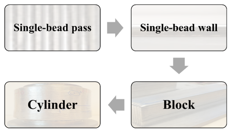 | Evaluations | |||||||
| Process stability | Bead shape and geometry | Inspection for lack of fusion, porosity, and inclusions | Post-production homogenization heat treatment | Chemical analysis | Microstructure characterization & study phase balance | Mechanical testing: strength and toughness | ||||
| Nitrogen measurement | Full chemical analysis | |||||||||
| 1 | Single-bead pass | Aim: Find a process window, giving a stable process in single-bead deposition. Approach: Systematic testing of combinations of parameters such as power, travel speed, wire feed rate, and wire pre-heating. | Y | Y | N | N | Y | N | Y | N |
| 2 | Single-bead wall | Aim: Find a process window, giving a stable process for single-bead wall deposition, control of the geometry and avoiding imperfections. Approach: Systematic testing of combinations of control system setting parameters and process parameters such as power, travel speed, wire feed rate, and wire pre-heating. | Y | Y | Y | N | Y | N | Y | N |
| 3 | Block | Aim: Apply learnings from previous stages to the production of a block to find a process window and control settings, giving a stable process and control of the geometry and avoiding imperfections. Approach: Systematic testing of combinations of the control system setting parameters and process parameters such as power, travel speed, wire feed rate, and wire pre-heating based on learnings from previous stages. | Y | Y | Y | Y | Y | Y | Y | Y |
| 4 | Cylinder | Aim: Verify developed deposition procedure by the production of a full-size near-net-shape component in the shape of a cylinder with 160 mm inner diameter, 30 mm thickness, and height of 140 mm. Approach: Systematic testing of combinations of control system setting parameters and process parameters such as power, travel speed, wire feed rate, and wire pre-heating, based on learnings from the stage. | Y | Y | Y | Y | Y | Y | Y | Y |
| C | Si | Mn | P | S | Cr | Ni | Mo | Cu | N | |
|---|---|---|---|---|---|---|---|---|---|---|
| Plate | 0.016 | 0.32 | 1.77 | 0.027 | <0.001 | 22.77 | 5.50 | 3.07 | 0.21 | 0.18 |
| Wire-batch 1 | 0.016 | 0.45 | 1.45 | 0.016 | 0.001 | 23.23 | 8.62 | 3.29 | 0.04 | 0.16 |
| Wire-batch 2 | 0.013 | 0.52 | 1.48 | 0.018 | 0.001 | 23.50 | 8.35 | 3.40 | 0.08 | 0.14 |
| Laser power (W) | 3500 |
| Wire feed rate (m/min) | 2 |
| Deposition speed (mm/s) | 10 |
| Focal length (mm) | 300 |
| Wavelength (nm) | 1040 |
| Spot size (mm) | 3 |
| Shielding gas | Argon |
| Hot-wire voltage (V)–Average value | 1.5 V in the first layer and 1 V in the subsequent layers |
| Hot-wire current (A)–Average values | ~100 A in the first layer and ~70 A in the subsequent layers |
| Sample | Single-Bead Pass | Single-Bead Wall | Block | Cylinder |
|---|---|---|---|---|
| Nitrogen (wt.%) | 0.14 | 0.11 | 0.11 | 0.11 |
| C | Si | Mn | P | S | Cr | Ni | Mo | Cu | V | |
|---|---|---|---|---|---|---|---|---|---|---|
| Block | 0.022 | 0.45 | 1.46 | 0.016 | 0.002 | 23.22 | 8.48 | 3.17 | 0.04 | 0.08 |
| Cylinder | 0.014 | 0.48 | 1.42 | 0.018 | <0.002 | 23.54 | 8.30 | 3.32 | 0.06 | 0.05 |
Publisher’s Note: MDPI stays neutral with regard to jurisdictional claims in published maps and institutional affiliations. |
© 2021 by the authors. Licensee MDPI, Basel, Switzerland. This article is an open access article distributed under the terms and conditions of the Creative Commons Attribution (CC BY) license (https://creativecommons.org/licenses/by/4.0/).
Share and Cite
Baghdadchi, A.; Hosseini, V.A.; Valiente Bermejo, M.A.; Axelsson, B.; Harati, E.; Högström, M.; Karlsson, L. Wire Laser Metal Deposition Additive Manufacturing of Duplex Stainless Steel Components—Development of a Systematic Methodology. Materials 2021, 14, 7170. https://doi.org/10.3390/ma14237170
Baghdadchi A, Hosseini VA, Valiente Bermejo MA, Axelsson B, Harati E, Högström M, Karlsson L. Wire Laser Metal Deposition Additive Manufacturing of Duplex Stainless Steel Components—Development of a Systematic Methodology. Materials. 2021; 14(23):7170. https://doi.org/10.3390/ma14237170
Chicago/Turabian StyleBaghdadchi, Amir, Vahid A. Hosseini, Maria Asuncion Valiente Bermejo, Björn Axelsson, Ebrahim Harati, Mats Högström, and Leif Karlsson. 2021. "Wire Laser Metal Deposition Additive Manufacturing of Duplex Stainless Steel Components—Development of a Systematic Methodology" Materials 14, no. 23: 7170. https://doi.org/10.3390/ma14237170
APA StyleBaghdadchi, A., Hosseini, V. A., Valiente Bermejo, M. A., Axelsson, B., Harati, E., Högström, M., & Karlsson, L. (2021). Wire Laser Metal Deposition Additive Manufacturing of Duplex Stainless Steel Components—Development of a Systematic Methodology. Materials, 14(23), 7170. https://doi.org/10.3390/ma14237170