
Electromagnetic Wave Shielding Properties of Amorphous Metallic Fiber-Reinforced High-Strength Concrete Using Waveguides

 ,
,  ,
, 
Abstract
:1. Introduction
2. Experimental Design and Method
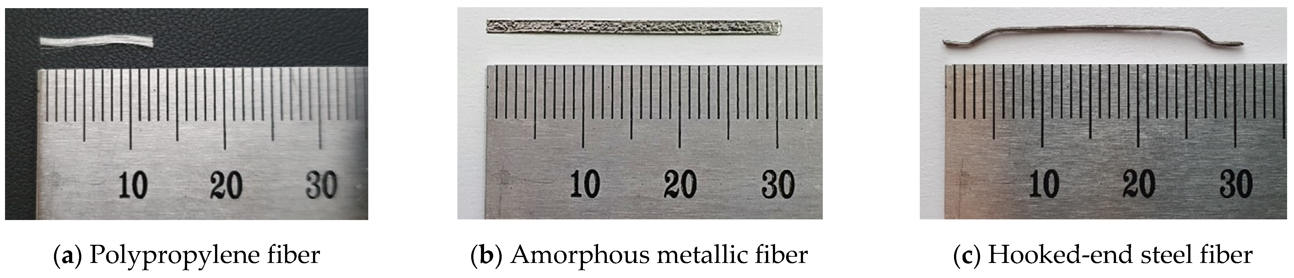
2.1. Materials
2.2. Experimental Plan and Mixture Proportions
2.3. Preparation of Specimens
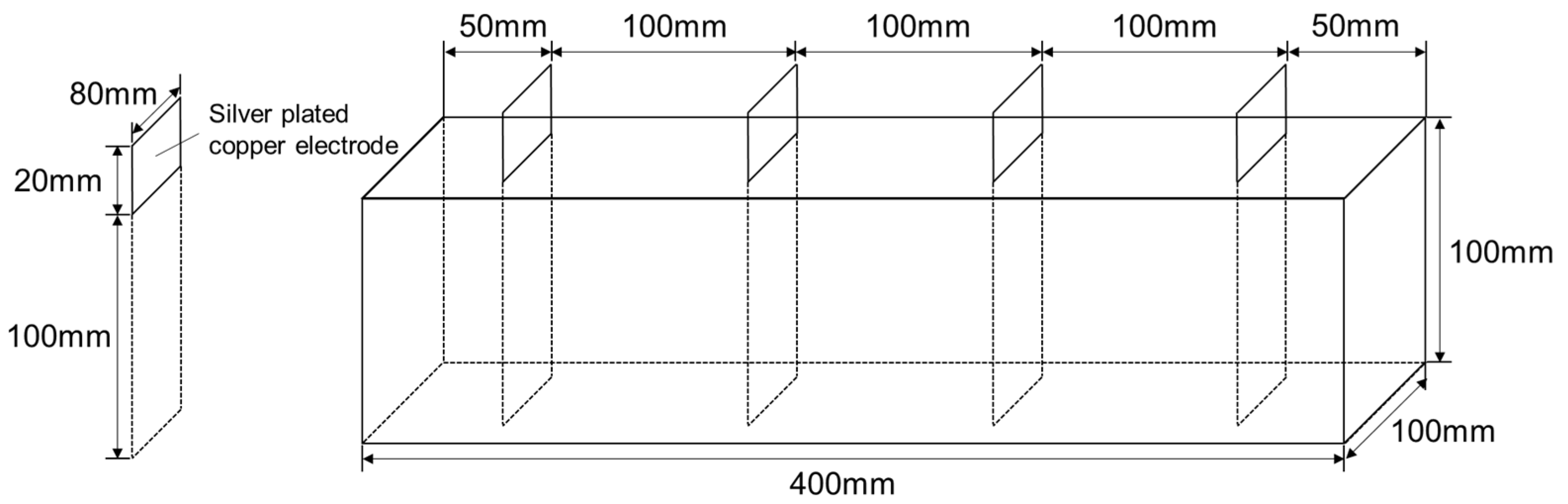
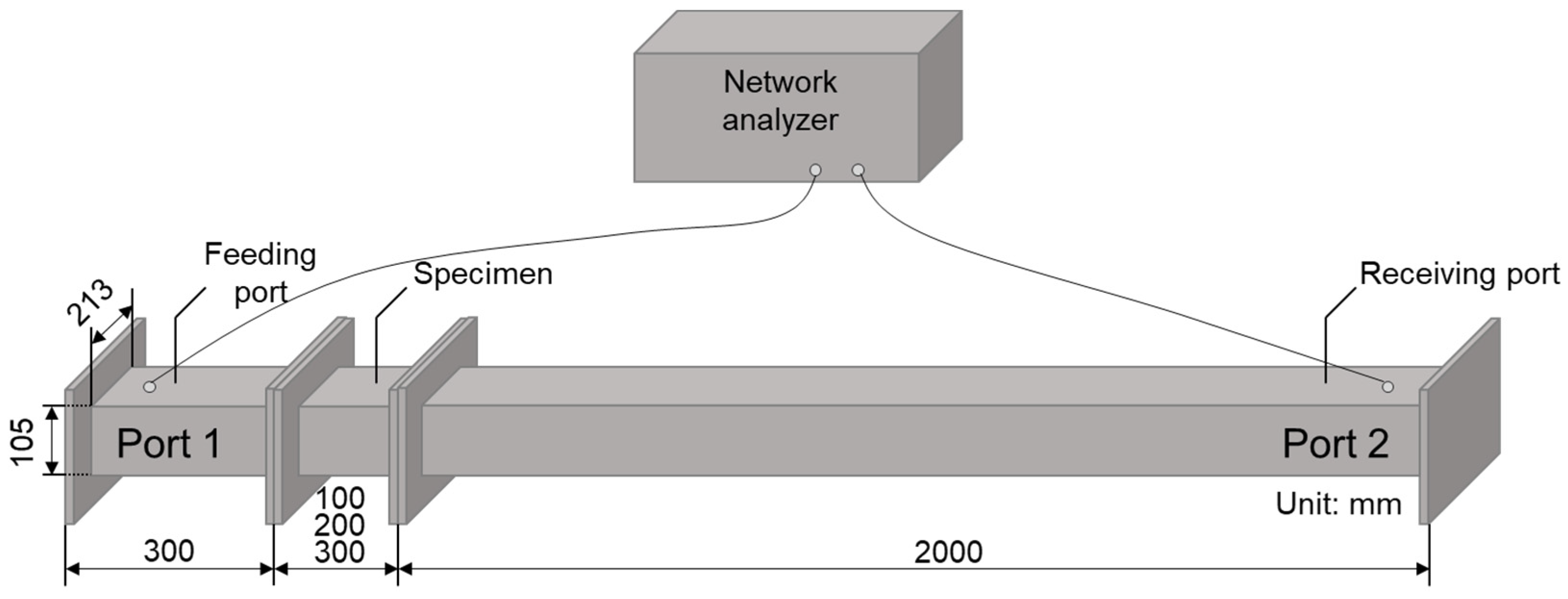
2.4. Experimental Method
3. Experimental Results and Discussion
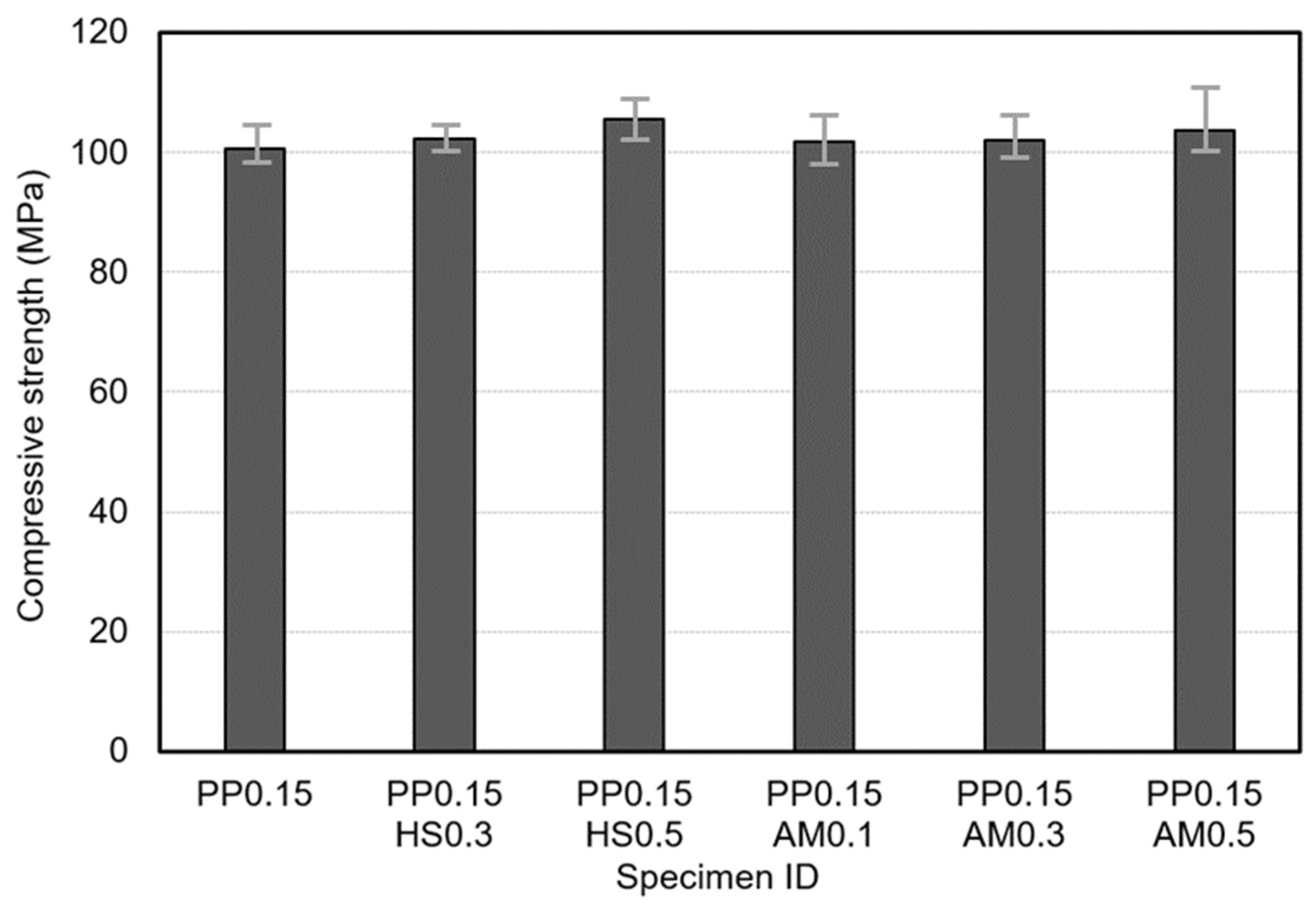
3.1. Compressive and Flexural Properties
3.2. Electrical Conductivity
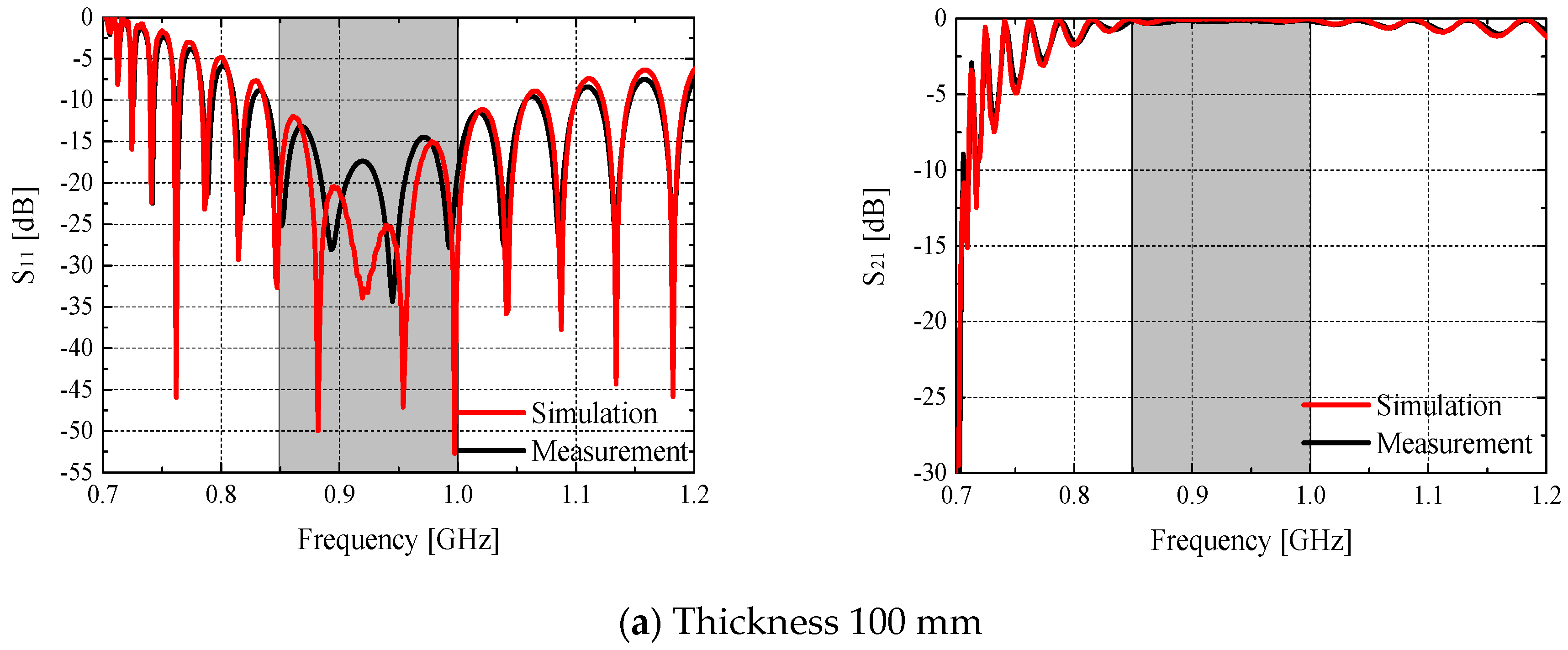
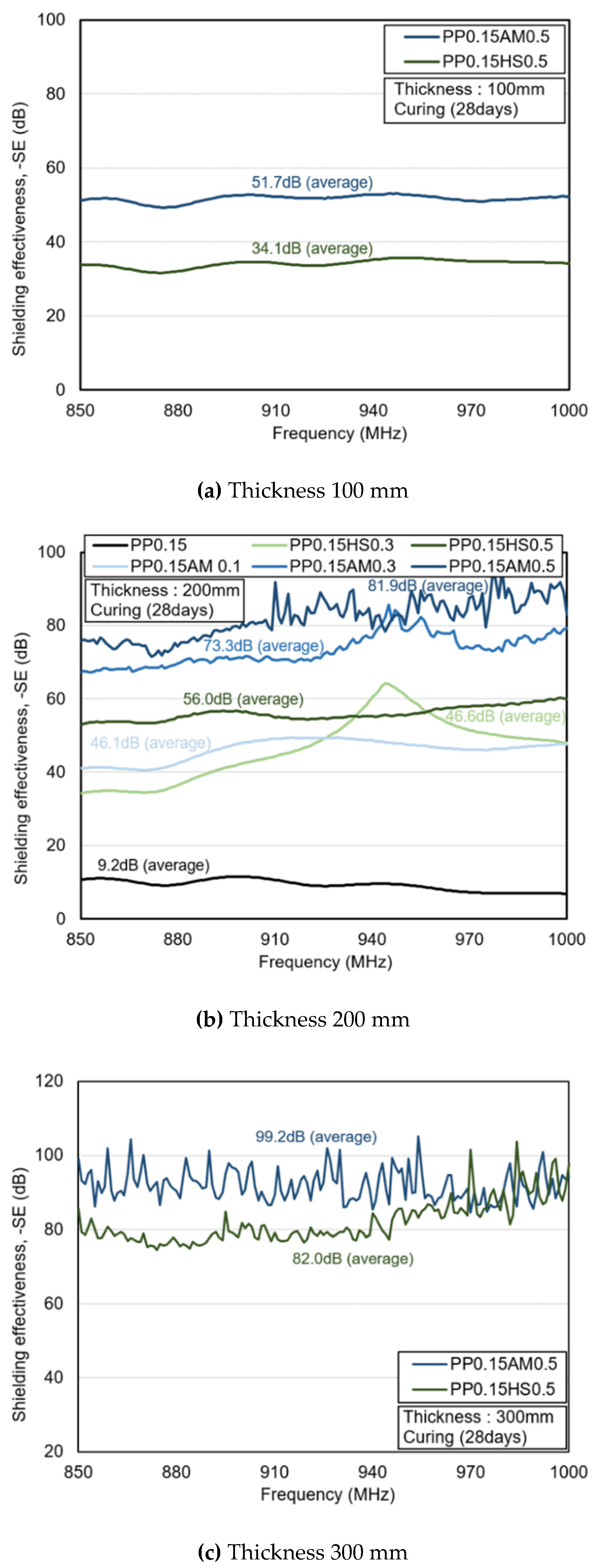
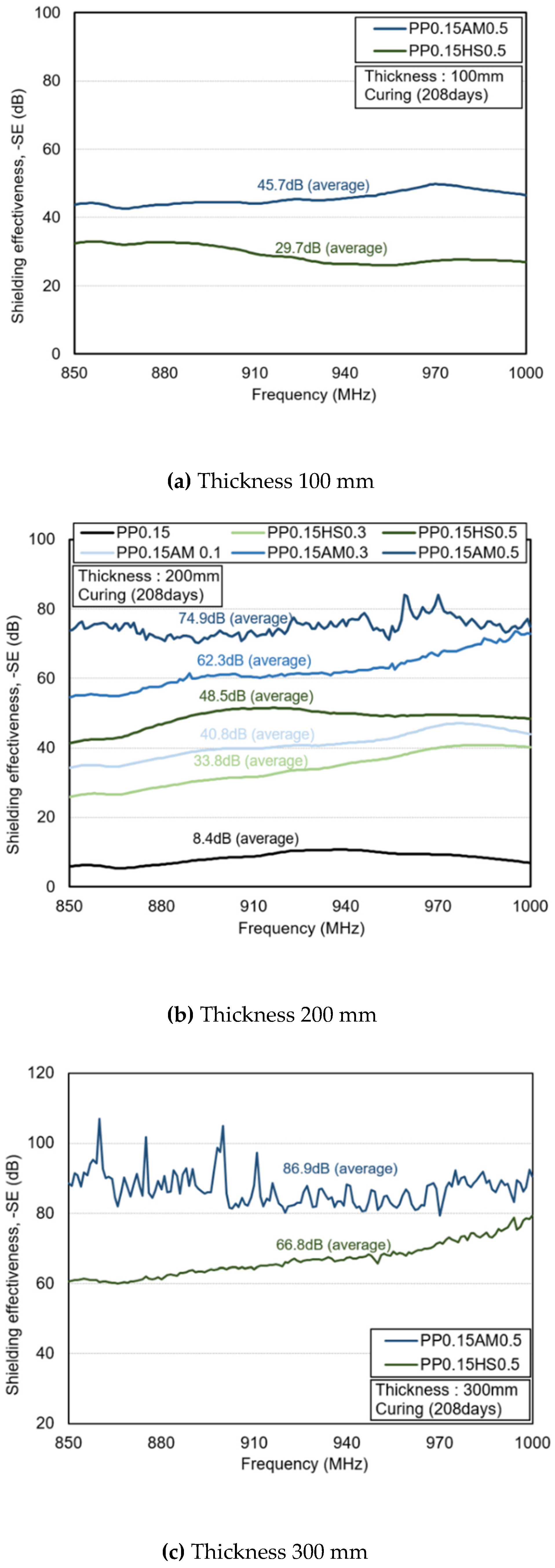
3.3. Electromagnetic Shielding Effectiveness
4. Conclusions
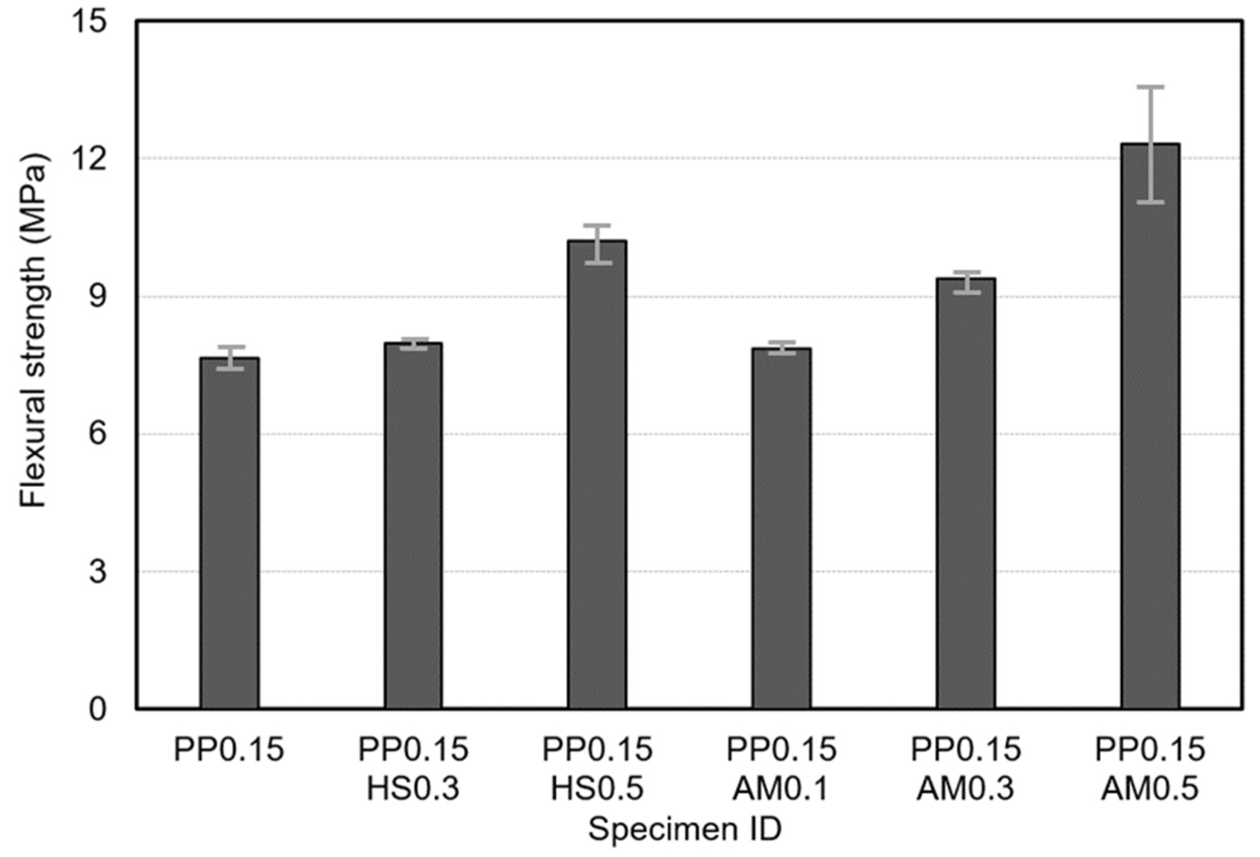
- Regardless of the reinforcing fibers, the flexural strength of fiber-reinforced, high-strength concrete was improved as the content of fibers increased owing to an improvement in the bridging effect. In particular, amorphous metallic fibers significantly improved the flexural strength compared to hooked-end steel fibers owing to the improved adhesion efficiency with the matrix. This was attributed to their larger surface area as thin plates and the fact that relatively more fibers were added at the same content.
- Amorphous metallic fibers are favorable for forming a conductive network because they can be added in large quantities owing to their low density, and have a large specific surface area as thin plates, even though they have the same length and length/equivalent diameter ratio value as hooked-end steel fibers. Therefore, it can be said that amorphous metallic fibers form a percolation conductive network at a lower content compared with hooked-end steel fibers.
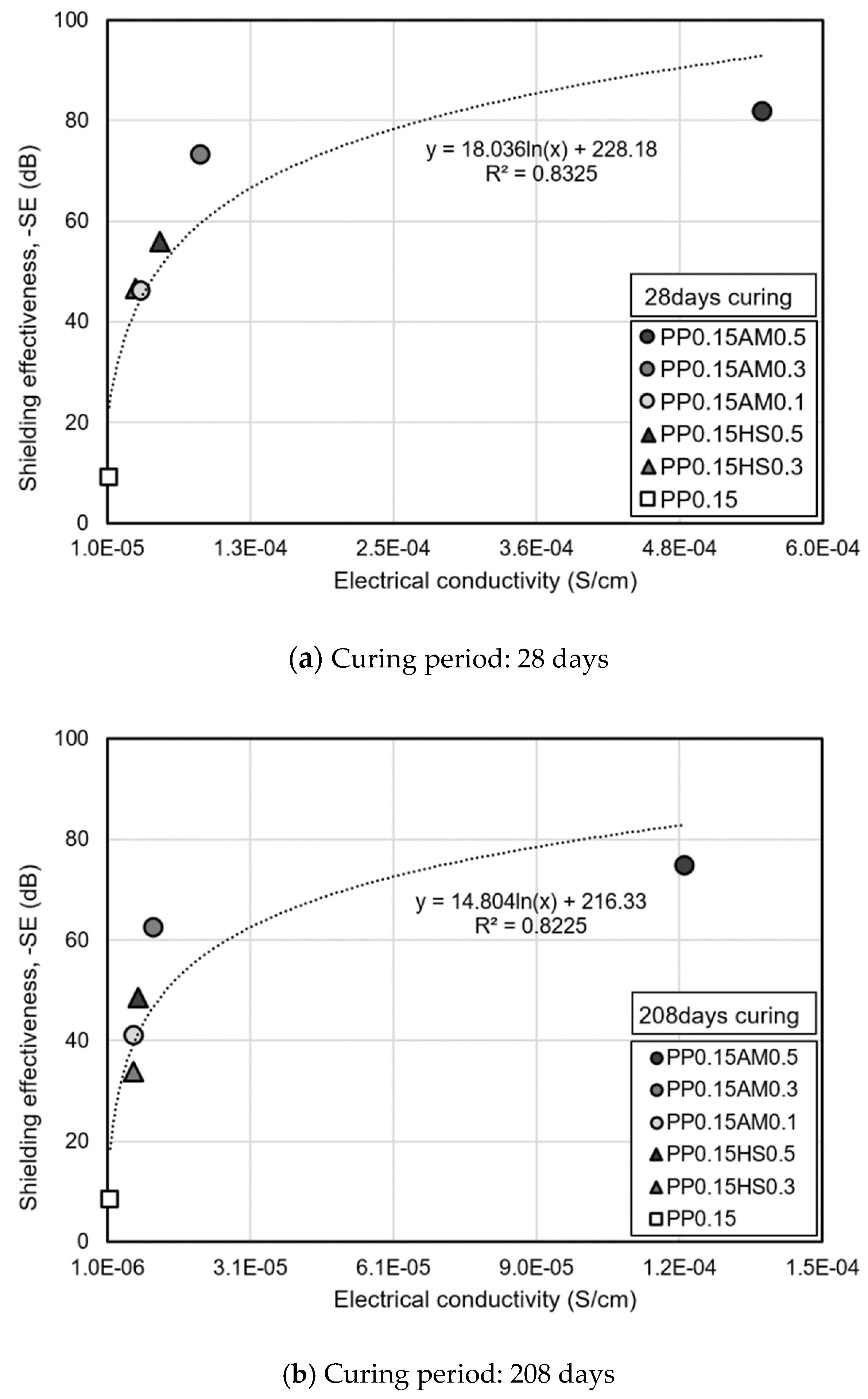
- The addition of metal fibers improved the electromagnetic shielding effectiveness (frequency range: 850–1000 Hz) owing to an improvement in electrical conductivity. Additionally, the shielding effectiveness of more than 80 dB (based on a thickness of 300 mm) was observed at a low moisture content after 208 days when amorphous metallic fibers (0.5 vol.%) were added. In addition, similar to the electrical conductivity, the efficient shielding effectiveness can be expected from amorphous metallic fibers at a low content compared with hooked-end steel fibers.
- Regardless of the age, the electromagnetic shielding effectiveness clearly improved as the electrical conductivity increased, and it can be expected that the shielding effectiveness will approach the saturation level when the fiber volume fraction of amorphous metallic fibers exceeds 0.5 vol.%. Meanwhile, given that the electrical conductivity and electromagnetic shielding effectiveness decrease owing to a reduction in the moisture content of the specimen, it is necessary to reduce the amount of moisture to conservatively evaluate the electromagnetic shielding performance.
Author Contributions
Funding
Institutional Review Board Statement
Informed Consent Statement
Conflicts of Interest
References
- Das, N.C.; Khastgir, D.; Chaki, T.K.; Chakraborty, A. Electromagnetic interference shielding effectiveness of carbon black and carbon fibre filled EVA and NR based composites. Compos. Part A 2000, 31, 1069–1081. [Google Scholar] [CrossRef]
- Kim, B.R.; Lee, H.K.; Park, S.H.; Kim, H.K. Electromagnetic interference shielding characteristics and shielding effectiveness of polyaniline-coated films. Thin Solid Film 2011, 519, 3492–3496. [Google Scholar] [CrossRef]
- Yoon, H.N.; Jang, D.; Lee, H.K.; Nam, I.W. Influence of carbon fiber additions on the electromagnetic wave shielding characteristics of CNT-cement composites. Constr. Build. Mater. 2021, 269, 121238. [Google Scholar] [CrossRef]
- Chung, D.D.L. Carbon materials for structural self-sensing, electromagnetic shielding and thermal interfacing. Carbon 2012, 50, 3342–3353. [Google Scholar] [CrossRef]
- Binggeli, C.; Rickli, H.; Ammann, P.; Brunckhorst, C.; Hufschmid, U.; Luechinger, R.; Duru, F. Induction ovens and electromagnetic interference: What is the risk for patients with implantable cardioverter defibrillators? J. Cardiov. Electrophys. 2005, 16, 399–401. [Google Scholar] [CrossRef] [PubMed]
- Radasky, W.A.; Baum, C.E.; Wik, M.W. Introduction to the special issue on high-power electromagnetics (HPEM) and intentional electromagnetic interference (IEMI). IEEE Trans. Electromagn. Compat. 2004, 46, 314–321. [Google Scholar] [CrossRef]
- Lemer, E.J. Military electronics: Electromagnetic pulses: Potential crippler: Three bombs, exploded in space over the US, could black out the nation, wipe out communications, and make computers useless. IEEE Spectr. 1981, 18, 41–46. [Google Scholar] [CrossRef]
- Beall, C.; Delzell, E.; Cole, P.; Brill, I. Brain tumors among electronics industry workers. Epidemiology 1996, 7, 125–130. [Google Scholar] [CrossRef]
- Grayson, J.K. Radiation exposure, socioeconomic status, and brain tumor risk in the US Air Force: A nested case-control study. Am. J. Epidemiol. 1996, 143, 480–486. [Google Scholar] [CrossRef]
- Szmigielski, S. Cancer morbidity in subjects occupationally exposed to high frequency (radiofrequency and microwave) electromagnetic radiation. Sci. Total Environ. 1996, 180, 9–17. [Google Scholar] [CrossRef]
- Wen, S.; Chung, D.D.L. Electromagnetic interference shielding reaching 70 dB in steel fiber cement. Cem. Concr. Res. 2004, 34, 329–332. [Google Scholar] [CrossRef]
- Wanasinghe, D.; Aslani, F.; Ma, G.; Habibi, D. Advancements in electromagnetic interference shielding cementitious composites. Const. Build. Mater. 2020, 231, 117116. [Google Scholar] [CrossRef]
- Li, Y.H.; Lue, J.T. Dielectric constants of single-wall carbon nanotubes at various frequencies. J. Nanosci. Nanotechnol. 2007, 7, 3185–3188. [Google Scholar] [CrossRef] [PubMed] [Green Version]
- Khushnood, R.A.; Ahmad, S.; Savi, P.; Tulliani, J.M.; Giorcelli, M.; Ferro, G.A. Improvement in electromagnetic interference shielding effectiveness of cement composites using carbonaceous nano/micro inerts. Const. Build. Mater. 2015, 85, 208–216. [Google Scholar] [CrossRef]
- Ma, P.C.; Siddiqui, N.A.; Marom, G.; Kim, J.K. Dispersion and functionalization of carbon nanotubes for polymer-based nanocomposites: A review. Compos. Part A Appl. Sci. Manuf. 2010, 41, 1345–1367. [Google Scholar] [CrossRef]
- Guan, H.; Liu, S.; Duan, Y.; Cheng, J. Cement based electromagnetic shielding and absorbing building materials. Cem. Concr. Compos. 2006, 28, 468–474. [Google Scholar] [CrossRef]
- Singh, A.P.; Gupta, B.K.; Mishra, M.; Chandra, A.; Mathur, R.B.; Dhawan, S.K. Multiwalled carbon nanotube/cement composites with exceptional electromagnetic interference shielding properties. Carbon 2013, 56, 86–96. [Google Scholar] [CrossRef]
- Lee, N.; Kim, S.; Park, G. The effects of multi-walled carbon nanotubes and steel fibers on the AC impedance and electromagnetic shielding effectiveness of high-performance, fiber-reinforced cementitious composites. Materials 2019, 12, 3591. [Google Scholar] [CrossRef] [Green Version]
- Berrocal, C.G.; Hornbostel, K.; Geiker, M.R.; Löfgren, I.; Lundgren, K.; Bekas, D.G. Electrical resistivity measurements in steel fibre reinforced cementitious materials. Cem. Concr. Compos. 2018, 89, 216–229. [Google Scholar] [CrossRef] [Green Version]
- Dehghanpour, H.; Yilmaz, K.; Afshari, F.; Ipek, M. Electrically conductive concrete: A laboratory-based investigation and numerical analysis approach. Constr. Build. Mater. 2020, 260, 119948. [Google Scholar] [CrossRef]
- Kim, H.; Kim, G.; Lee, S.; Son, M.; Choe, G.; Nam, J. Strain rate effects on the compressive and tensile behavior of bundle-type polyamide fiber-reinforced cementitious composites. Compos. Part B: Eng. 2019, 160, 50–65. [Google Scholar] [CrossRef]
- Kim, H.; Kim, G.; Gucunski, N.; Nam, J.; Jeon, J. Assessment of flexural toughness and impact resistance of bundle-type polyamide fiber-reinforced concrete. Compos. Part B Eng. 2015, 78, 431–446. [Google Scholar] [CrossRef]
- Yang, J.M.; Shin, H.O.; Yoo, D.Y. Benefits of using amorphous metallic fibers in concrete pavement for long-term performance. Arch. Civ. Mech. Eng. 2017, 17, 750–760. [Google Scholar] [CrossRef]
- Lee, S.; Kim, G.; Kim, H.; Son, M.; Choe, G.; Kobayashi, K.; Nam, J. Impact resistance, flexural and tensile properties of amorphous metallic fiber-reinforced cementitious composites according to fiber length. Constr. Build. Mater. 2021, 271, 121872. [Google Scholar] [CrossRef]
- Kim, H.; Kim, G.; Lee, S.; Choe, G.; Nam, J.; Noguchi, T.; Mechtcherine, V. Effects of strain rate on the tensile behavior of cementitious composites made with amorphous metallic fiber. Cem. Concr. Compos. 2020, 108, 103519. [Google Scholar] [CrossRef]
- Kim, H.; Kim, G.; Lee, S.; Choe, G.; Noguchi, T.; Nam, J. Direct tensile behavior of amorphous metallic fiber-reinforced cementitious composites: Effect of fiber length, fiber volume fraction, and strain rate. Compos. Part B: Eng. 2019, 177, 107430. [Google Scholar] [CrossRef]
- Choe, G.; Kim, G.; Kim, H.; Hwang, E.; Lee, S.; Nam, J. Effect of amorphous metallic fiber on mechanical properties of high-strength concrete exposed to high-temperature. Constr. Build. Mater. 2019, 218, 448–456. [Google Scholar] [CrossRef]
- Choe, G.; Kim, G.; Kim, H.; Hwang, E.; Lee, S.; Son, M.; Nam, J. Influence of amorphous metallic fibers on spalling properties of high-strength concrete exposed to high temperature. Constr. Build. Mater. 2020, 263, 120711. [Google Scholar] [CrossRef]
- Liao, J.; Yang, K.Y.; Zeng, J.J.; Quach, W.M.; Ye, Y.Y.; Zhang, L. Compressive behavior of FRP-confined ultra-high performance concrete (UHPC) in circular columns. Eng. Struct. 2021, 249, 113246. [Google Scholar] [CrossRef]
- Ye, Y.Y.; Smith, S.T.; Zeng, J.J.; Zhuge, Y.; Quach, W.M. Novel ultra-high-performance concrete composite plates reinforced with FRP grid: Development and mechanical behaviour. Compos. Struct. 2021, 269, 114033. [Google Scholar] [CrossRef]
- Schneider, U.; Schwesinger, P.; Debicki, G.; Diederichs, U.; Felicetti, R.; Franssen, J.M.; Jumppanen, U.M.; Khoury, G.A.; Millard, A.; Morris, W.A.; et al. RILEM Recommendations: Part 4: Tensile strength for service and accident conditions. Mater. Struct. 2000, 33, 219–223. [Google Scholar]
- American Society for Testing and Materials (ASTM). Standard Test Method for Compressive Strength of Cylindrical Concrete Specimens, ASTM C 39/39M; American Society for Testing and Materials: West Conshohocken, PA, USA, 2014; pp. 1–7. [Google Scholar]
- American Society for Testing and Materials (ASTM). Standard Test Method for Flexural Performance of Fiber-Reinforced Concrete (Using Beam with Third-Point Loading), ASTM C1609/C1609M; ASTM International: West Conshohocken, PA, USA, 2012; pp. 1–9. [Google Scholar]
- Nam, I.W.; Souri, H.; Lee, H.K. Percolation threshold and piezoresistive response of multi-wall carbon nanotube/cement composites. Smart Struct. Syst. 2016, 18, 217–231. [Google Scholar] [CrossRef]
- Micheli, D.; Pastore, R.; Vricella, A.; Morles, R.B.; Marchetti, M.; Delfini, A.; Moglie, F.; Primiani, V.M. Electromagnetic characterization and shielding effectiveness of concrete composite reinforced with carbon nanotubes in the mobile phones frequency band. Mater. Sci. Eng. B 2014, 188, 119–129. [Google Scholar] [CrossRef]
- Micheli, D.; Vricella, A.; Pastore, R.; Delfini, A.; Morles, R.B.; Marchetti, M.; Donnini, J. Electromagnetic properties of carbon nanotube reinforced concrete composites for frequency selective shielding structures. Constr. Build. Mater. 2017, 131, 267–277. [Google Scholar] [CrossRef]
- Gomis, J.; Galao, O.; Gomis, V.; Zornoza, E.; Garcés, P. Self-heating and deicing conductive cement. Experimental study and modeling. Constr. Build. Mater. 2015, 75, 442–449. [Google Scholar] [CrossRef]
- Xie, P.; Gu, P.; Beaudoin, J.J. Electrical percolation phenomena in cement composites containing conductive fibres. J. Mater. Sci. 1996, 31, 4093–4097. [Google Scholar] [CrossRef]
- Department of Defense. MIL-STD-188-125-1 High-Altitude Electromagnetic (HEMP) Protection for Ground Based C41 Facilities; US Military Specs/Standards/Handbooks; Department of Defense: Arlington, VA, USA, 2005; p. 106. [Google Scholar]
- Wanasinghe, D.; Aslani, F.; Ma, G. Electromagnetic shielding properties of carbon fibre reinforced cementitious composites. Constr. Build. Mater. 2020, 260, 120439. [Google Scholar] [CrossRef]
- Al-Saleh, M.H.; Sundararaj, U. Electromagnetic interference shielding mechanisms of CNT/polymer composites. Carbon 2009, 47, 1738–1746. [Google Scholar] [CrossRef]
- Jana, P.B.; Mallick, A.K.; De, S.K. Effects of sample thickness and fiber aspect ratio on EMI shielding effectiveness of carbon fiber filled polychloroprene composites in the X-band frequency range. IEEE Trans. Electromagn. Compat. 1992, 34, 478–481. [Google Scholar] [CrossRef]


| Mechanical Properties |
|---|
| Length: 15 mm, diameter: 20 µm, density: 0.91 g/cm3, melting point: 170 °C |
| Length: 30 mm, width: 1.6 mm, thickness: 29 µm, density: 7.2 g/cm3, tensile strength: 1400 MPa, specific surface area: 9.6 m2/kg |
| Length: 30 mm, diameter: 0.25 mm, density: 7.85 g/cm3, tensile strength: 1140 MPa, specific surface area: 1.0 m2/kg |
| Materials | Mechanical Properties |
|---|---|
| Cement | Ordinary Portland cement, density: 3150 kg/m3, fineness: 320 m2/kg |
| Silica fume | Density: 2500 kg/m3, fineness: 20,000 m2/kg |
| Ground granulated blast-furnace slag | Density: 2500 kg/m3, fineness: 600 m2/kg |
| Coarse aggregate | Crushed granitic aggregate, maximum size: 20 mm, density: 2700 kg/m3, absorption: 0.9% |
| Fine aggregate | River sand, density: 2650 kg/m3, absorption: 1%, fineness modulus: 2.6 |
| Super plasticizer | Polycarboxylic acid type |
| Identity 1 | Fiber Type and Volume Fraction | Evaluation Items | ||
|---|---|---|---|---|
| PP | HS | AM | ||
| PP0.15 | 0.15 | - | - | Compressive strength (MPa) Flexural strength (MPa) Electrical conductivity (S/cm) Electromagnetic shielding effectiveness (dB) |
| PP0.15HS0.3 | 0.3 | - | ||
| PP0.15HS0.5 | 0.5 | - | ||
| PP0.15AM0.1 | - | 0.1 | ||
| PP0.15AM0.3 | - | 0.3 | ||
| PP0.15AM0.5 | - | 0.5 | ||
| W/B | C/B | SF/B | GGBS/B | S/a | Fibers (kg) | ||
|---|---|---|---|---|---|---|---|
| Polypropylene Fiber | Amorphous Metallic Fiber | Hooked-End Steel Fiber | |||||
| 0.19 | 0.7 | 0.15 | 0.15 | 0.45 | 1.4 (0.15 vol.%) | 7.2 (0.1 vol.%) 21.6 (0.3 vol.%) 36.0 (0.5 vol.%) | 23.6 (0.3 vol.%) 39.3 (0.5 vol.%) |
| Curing Age (Days) | Moisture Content (%) | |||||
|---|---|---|---|---|---|---|
| PP0.15 | PP0.15 HS0.3 | PP0.15 HS0.5 | PP0.15 AM0.1 | PP0.15 AM0.3 | PP0.15 AM0.5 | |
| 28 | 6.0 | 5.8 | 5.9 | 5.9 | 5.8 | 5.8 |
| 208 | 2.7 | 2.8 | 2.7 | 2.6 | 2.6 | 2.7 |
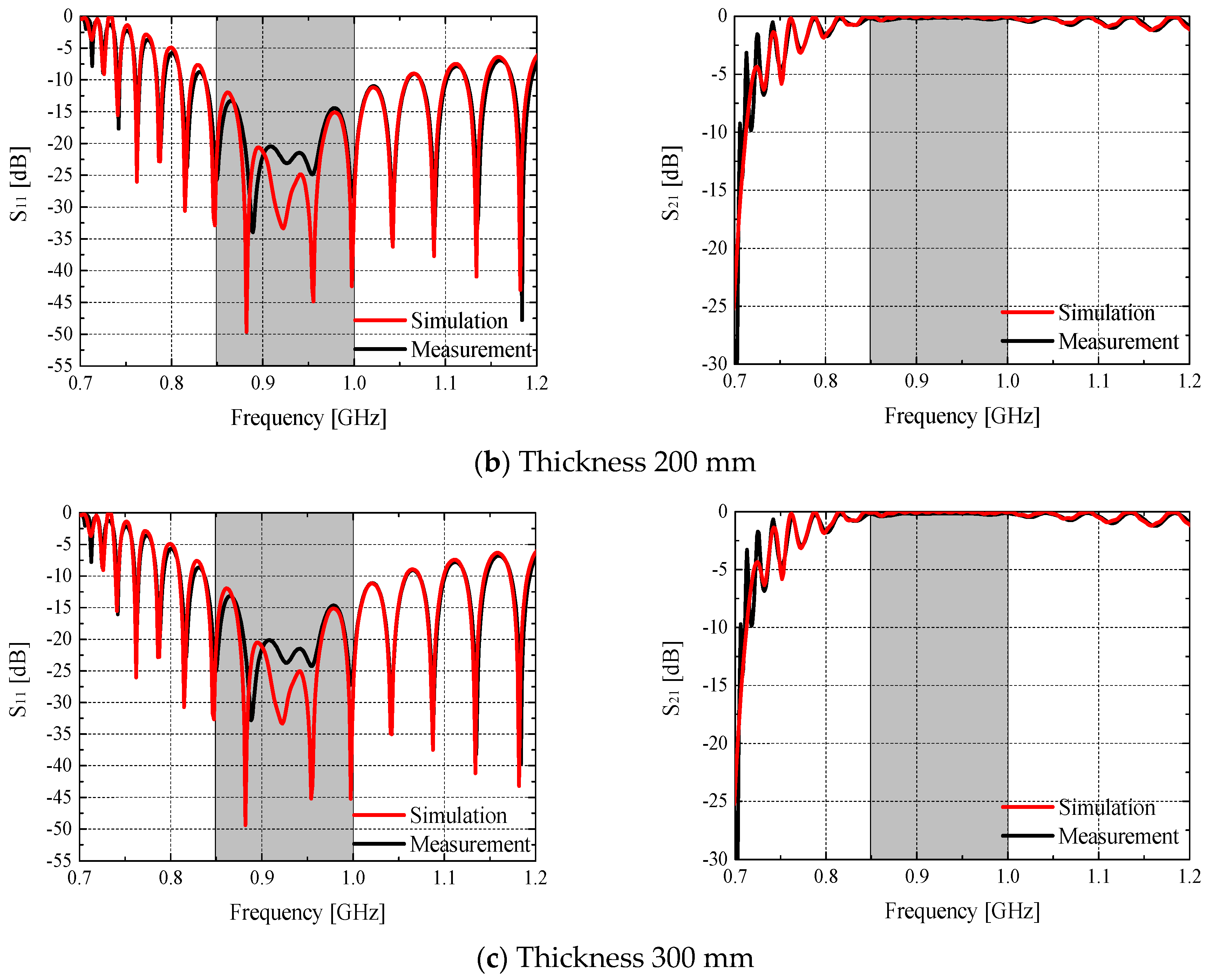
| Frequency (GHz) | 0.85 | 0.925 | 1.0 | ||||
|---|---|---|---|---|---|---|---|
| Simulation | Measurement | Simulation | Measurement | Simulation | Measurement | ||
| Thickness: 100 mm | S11 (dB) | −20.73 | −23.44 | −32.01 | −17.81 | −28.74 | −18.68 |
| S21 (dB) | −0.05 | −0.14 | −0.03 | −0.17 | −0.02 | −0.16 | |
| Thickness: 200 mm | S11 (dB) | −20.66 | −25.52 | −32.21 | −23.06 | −29.52 | −25.69 |
| S21 (dB) | −0.1 | −0.16 | −0.06 | −0.15 | −0.05 | −0.13 | |
| Thickness: 300 mm | S11 (dB) | −20.6 | −24.9 | −32.24 | −23.61 | −28.86 | −24.81 |
| S21 (dB) | −0.1 | −0.17 | −0.06 | −0.16 | −0.05 | −0.15 | |
Publisher’s Note: MDPI stays neutral with regard to jurisdictional claims in published maps and institutional affiliations. |
© 2021 by the authors. Licensee MDPI, Basel, Switzerland. This article is an open access article distributed under the terms and conditions of the Creative Commons Attribution (CC BY) license (https://creativecommons.org/licenses/by/4.0/).
Share and Cite
Lee, S.; Kim, G.; Kim, H.; Son, M.; Lee, Y.; Choi, Y.; Woo, J.; Nam, J. Electromagnetic Wave Shielding Properties of Amorphous Metallic Fiber-Reinforced High-Strength Concrete Using Waveguides. Materials 2021, 14, 7052. https://doi.org/10.3390/ma14227052
Lee S, Kim G, Kim H, Son M, Lee Y, Choi Y, Woo J, Nam J. Electromagnetic Wave Shielding Properties of Amorphous Metallic Fiber-Reinforced High-Strength Concrete Using Waveguides. Materials. 2021; 14(22):7052. https://doi.org/10.3390/ma14227052
Chicago/Turabian StyleLee, Sangkyu, Gyuyong Kim, Hongseop Kim, Minjae Son, Yaechan Lee, Yoonseon Choi, Jongmyung Woo, and Jeongsoo Nam. 2021. "Electromagnetic Wave Shielding Properties of Amorphous Metallic Fiber-Reinforced High-Strength Concrete Using Waveguides" Materials 14, no. 22: 7052. https://doi.org/10.3390/ma14227052
APA StyleLee, S., Kim, G., Kim, H., Son, M., Lee, Y., Choi, Y., Woo, J., & Nam, J. (2021). Electromagnetic Wave Shielding Properties of Amorphous Metallic Fiber-Reinforced High-Strength Concrete Using Waveguides. Materials, 14(22), 7052. https://doi.org/10.3390/ma14227052