
Advanced Constitutive Modeling of the Thixotropic Elasto-Visco-Plastic Behavior of Blood: Steady-State Blood Flow in Microtubes


Abstract
1. Introduction
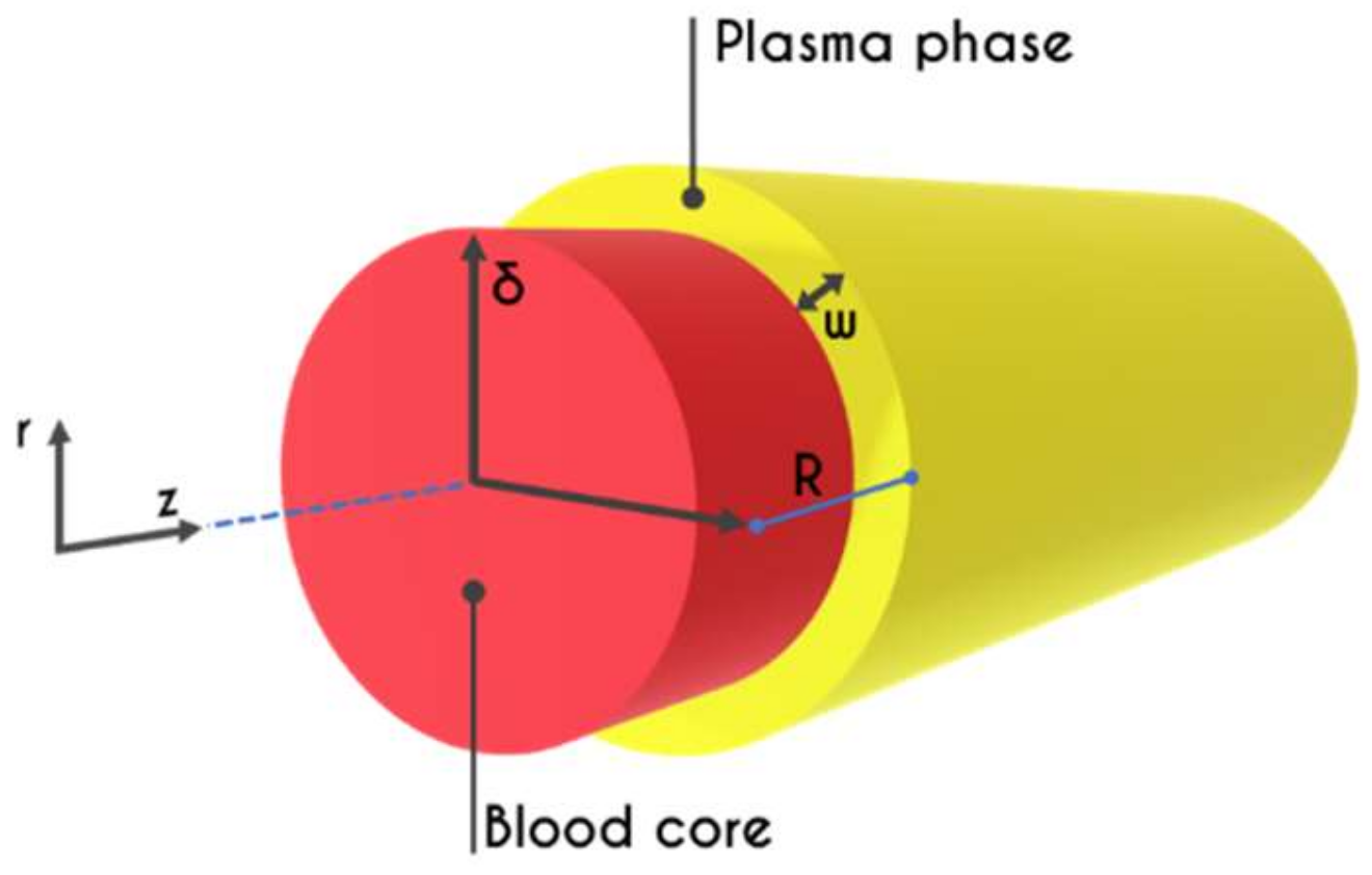
2. Problem Formulation
2.1. Whole Blood Constitutive Modeling
2.2. Plasma Constitutive Modeling
2.3. Hemodynamical Constraints
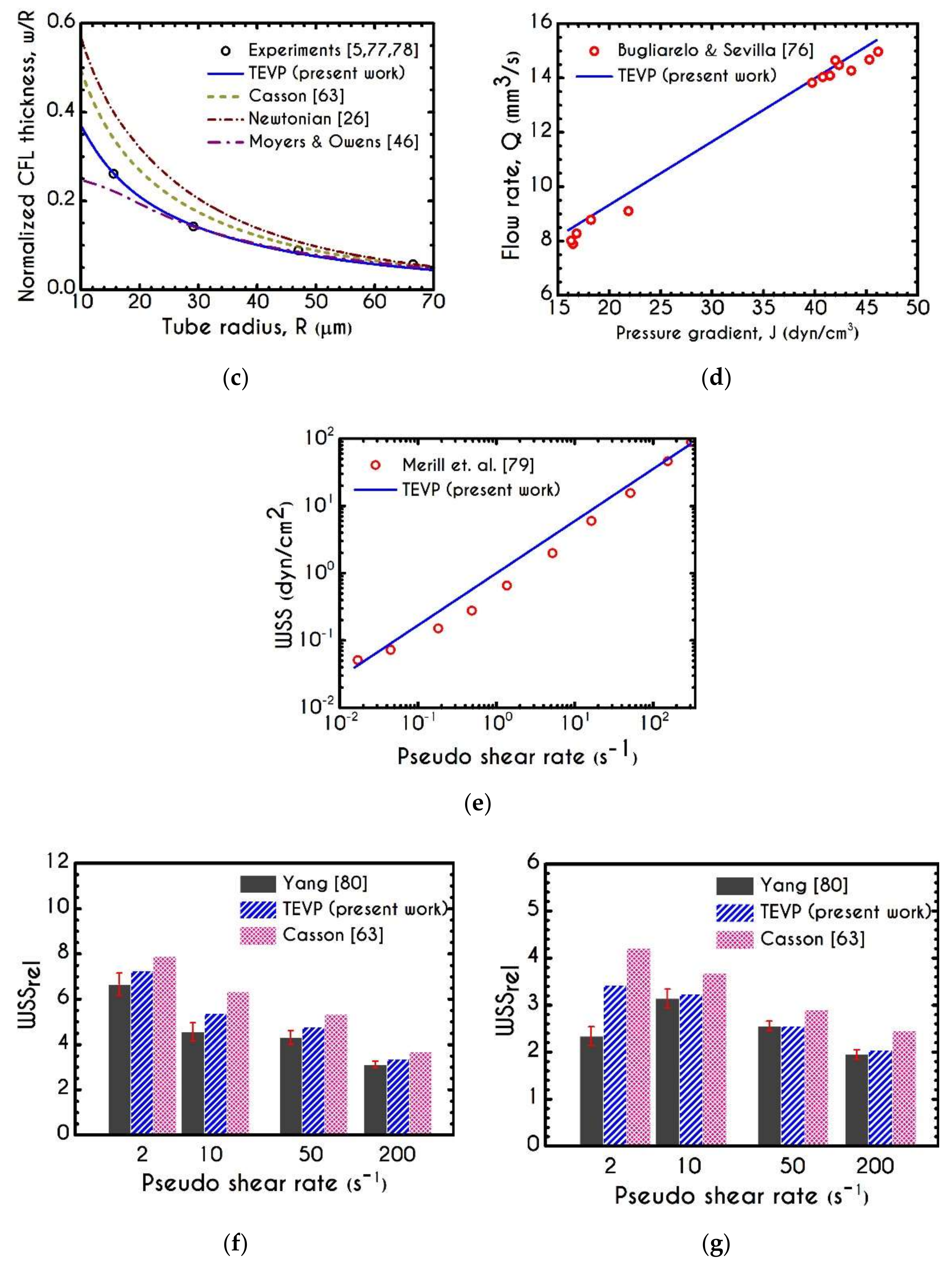
3. Validation
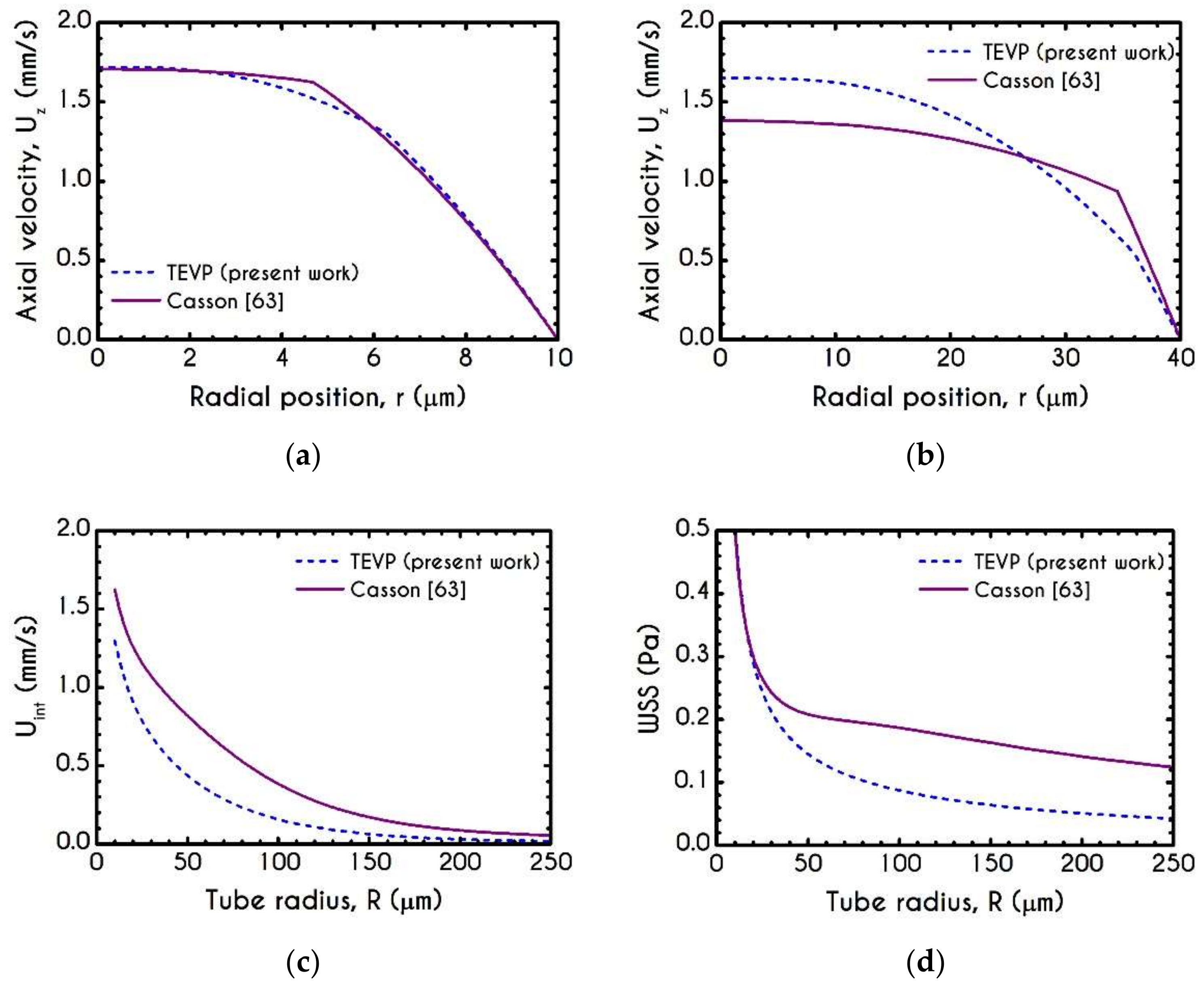
4. Numerical Results
4.1. Comparison with an Inelastic Model
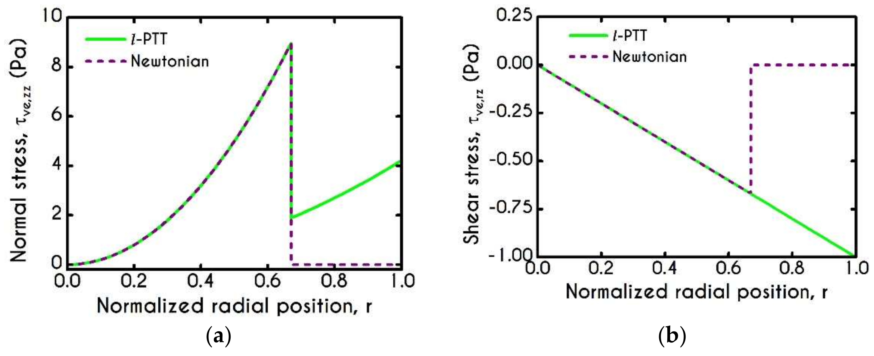
4.2. Effect of Proteinic Elasticity in the Plasma Layer
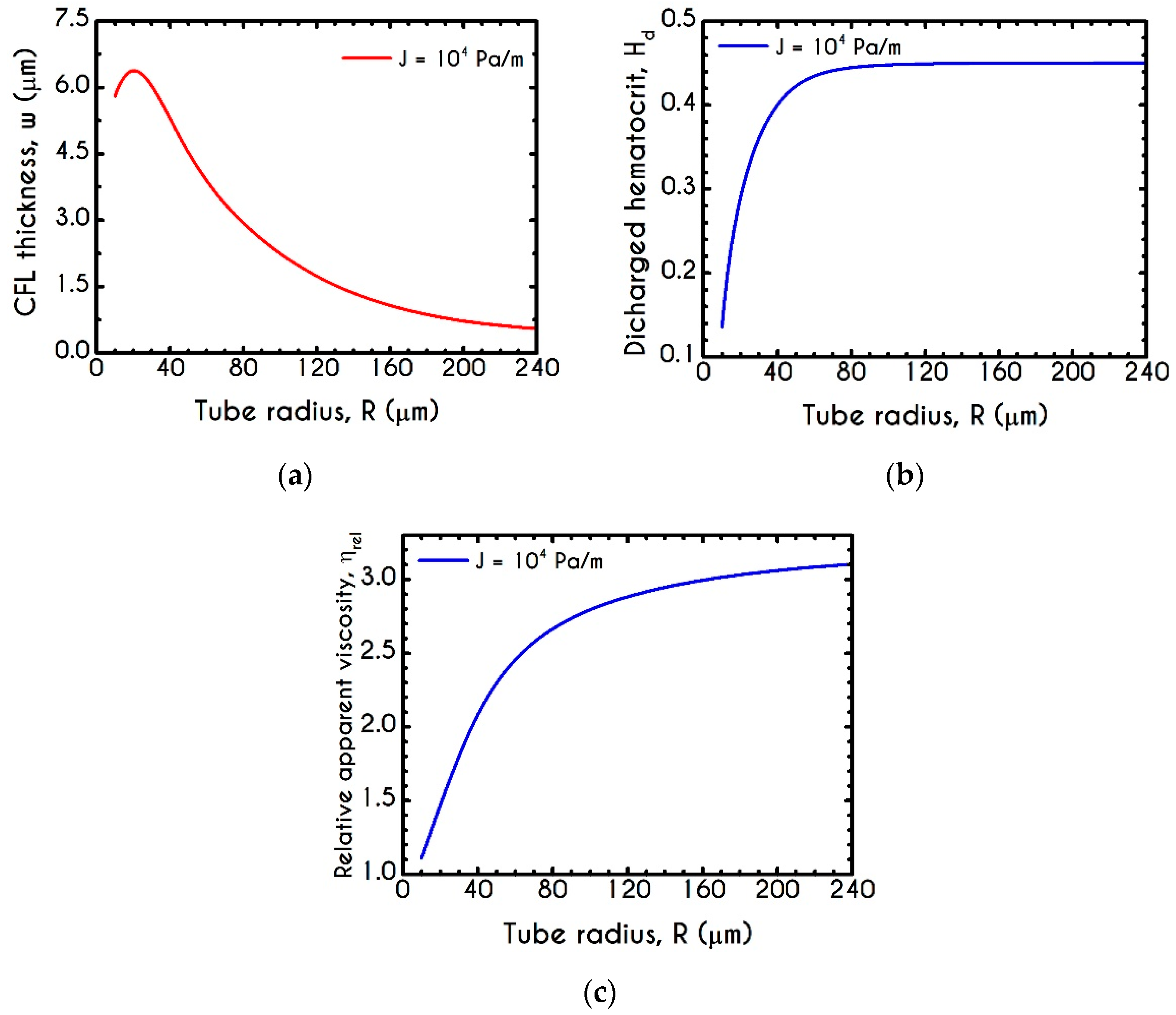
4.3. Effect of Radius
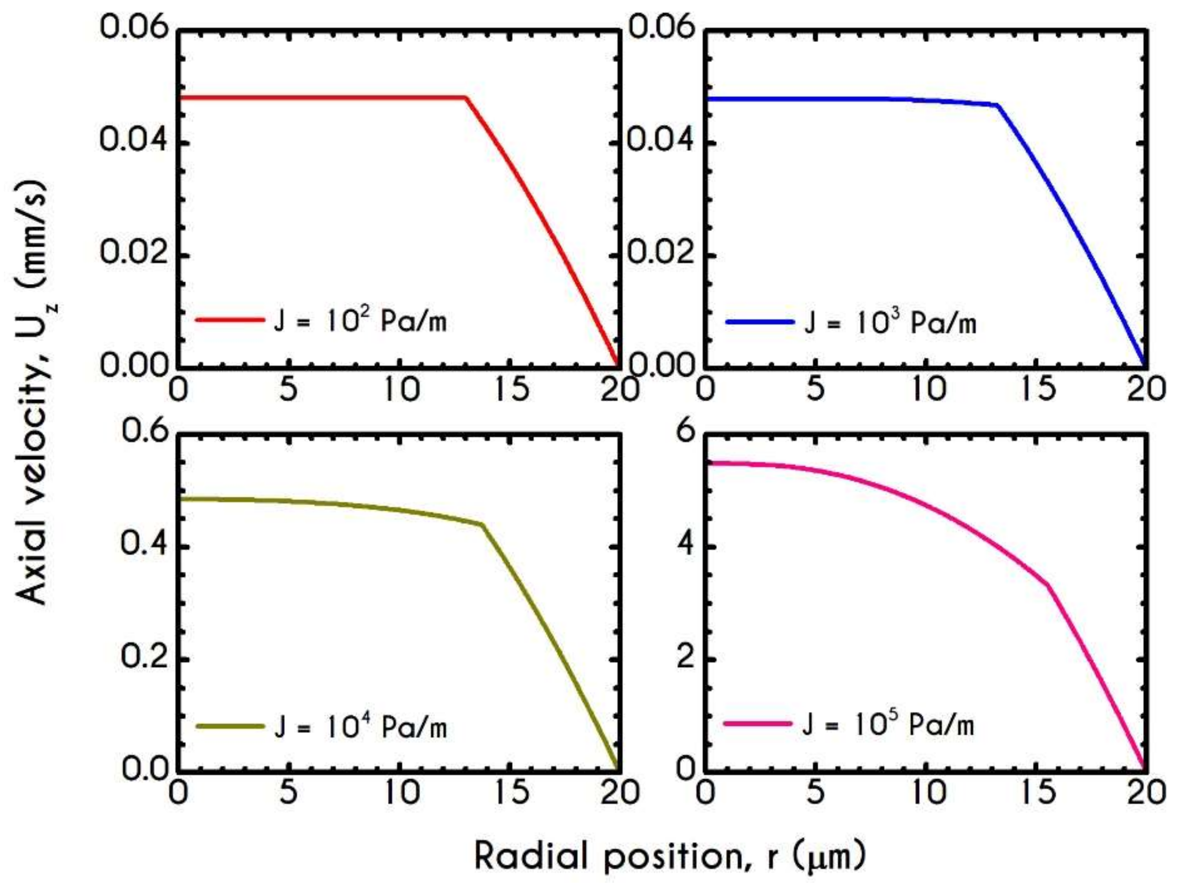
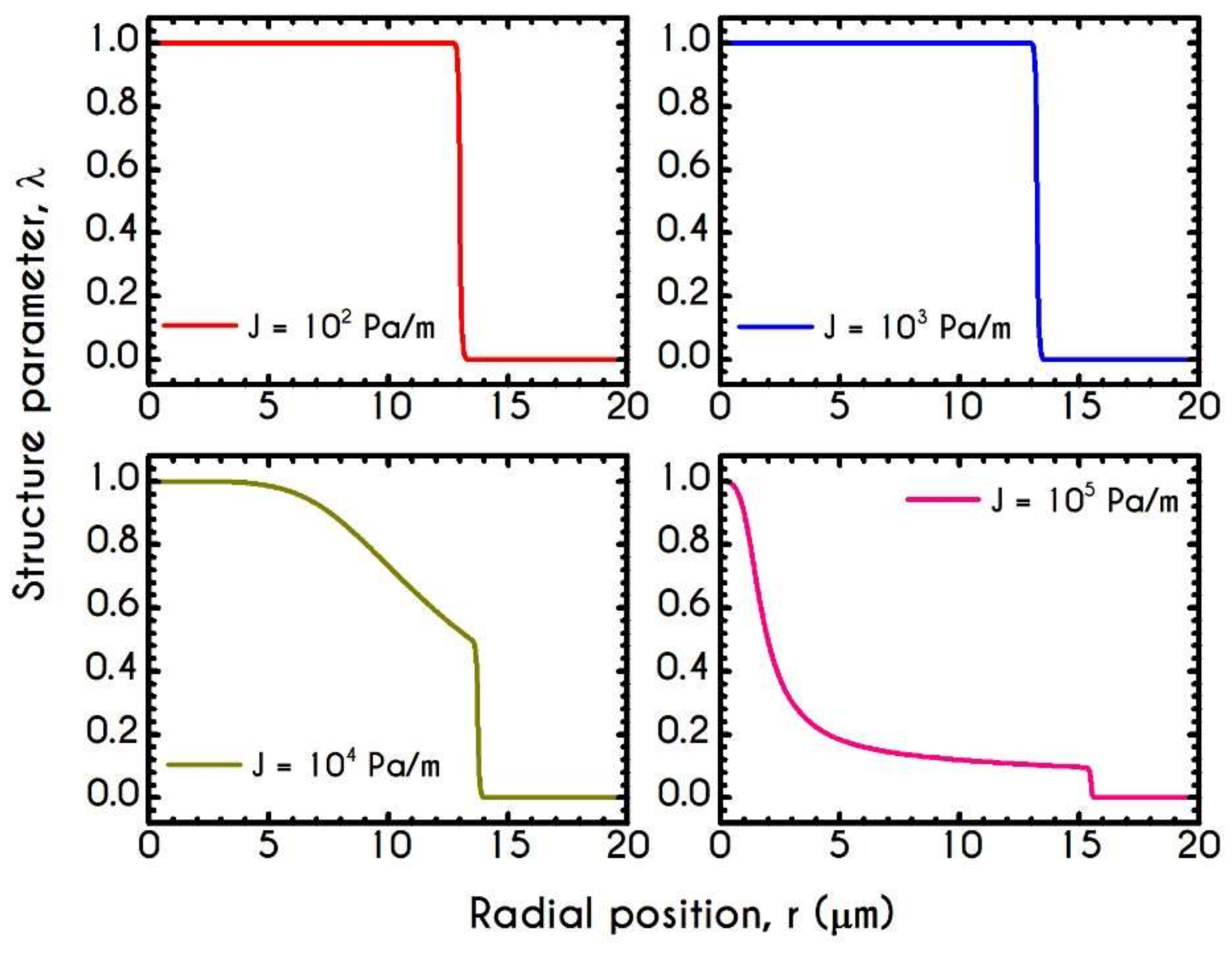
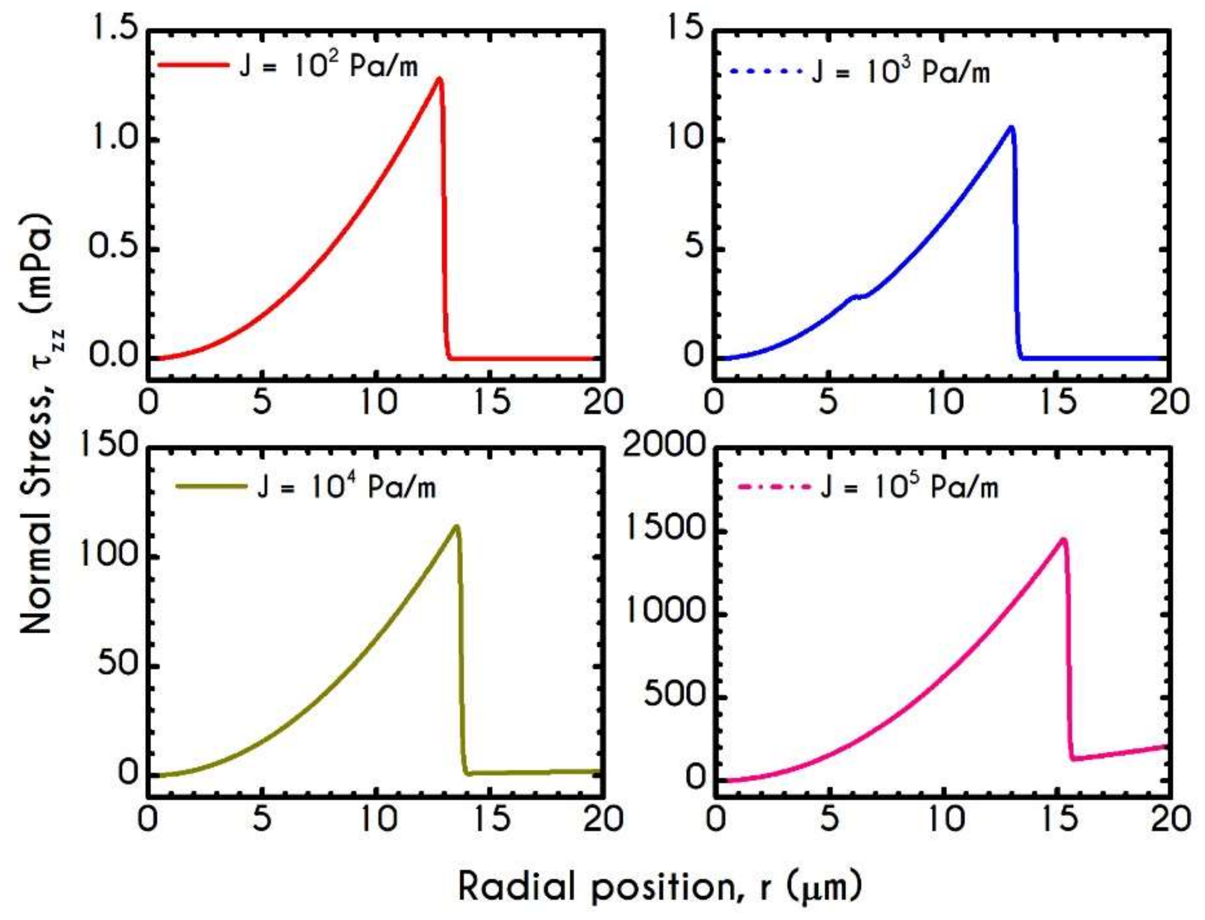
4.4. Effect of Pressure Gradient
5. Conclusions
Author Contributions
Funding
Institutional Review Board Statement
Informed Consent Statement
Data Availability Statement
Conflicts of Interest
Appendix A
Appendix B

Appendix C

References
- Varga, Z.; Flammer, A.J.; Steiger, P.; Haberecker, M.; Andermatt, R.; Zinkernagel, A.S.; Mehra, M.R.; Schuepbach, R.A.; Ruschitzka, F.; Moch, H. Endothelial Cell Infection and Endotheliitis in COVID-19. Lancet 2020, 395, 1417–1418. [Google Scholar] [CrossRef]
- Zatz, R.; Brenner, B.M. Pathogenesis of Diabetic Microangiopathy. The Hemodynamic View. Am. J. Med. 1986, 80, 443–453. [Google Scholar] [CrossRef]
- Pries, A.R.; Secomb, T.W. Rheology of the Microcirculation. Clin. Hemorheol. Microcirc. 2003, 29, 143–148. [Google Scholar] [PubMed]
- Giannokostas, K.; Moschopoulos, P.; Varchanis, S.; Dimakopoulos, Y.; Tsamopoulos, J. Advanced Constitutive Modeling of the Thixotropic Elasto-Visco-Plastic Behavior of Blood: Description of the Model and Rheological Predictions. Materials 2020, 13, E4184. [Google Scholar] [CrossRef] [PubMed]
- Reinke, W.; Gaehtgens, P.; Johnson, P.C. Blood Viscosity in Small Tubes: Effect of Shear Rate, Aggregation, and Sedimentation. Am. J. Physiol. Heart Circ. Physiol. 1987, 253, 540–547. [Google Scholar] [CrossRef] [PubMed]
- Chien, S.; Jan, K. Ultrastructural Basis of the Mechanism of Rouleaux Formation. Microvasc. Res. 1973, 5, 155–166. [Google Scholar] [CrossRef]
- Shiga, T.; Maeda, N.; Kon, K. Erythrocyte Rheology. Crit. Rev. Oncol. Hematol. 1990, 10, 9–48. [Google Scholar] [CrossRef]
- Tomaiuolo, G.; Carciati, A.; Caserta, S.; Guido, S. Blood Linear Viscoelasticity by Small Amplitude Oscillatory Flow. Rheol. Acta 2016, 55, 485–495. [Google Scholar] [CrossRef]
- Trybala, A.; Starov, V. Kinetics of Spreading Wetting of Blood over Porous Substrates. Curr. Opin. Colloid Interface Sci. 2018, 36, 84–89. [Google Scholar] [CrossRef]
- Merrill, E.W.; Cheng, C.S.; Pelletier, G.A. Yield Stress of Normal Human Blood as a Function of Endogenous Fibrinogen. J. Appl. Physiol. 1969, 26, 1–3. [Google Scholar] [CrossRef]
- Picart, C.; Piau, J.; Galliard, H.; Carpentier, P.; Carpentier, P. Human Blood Shear Yield Stress and Its Hematocrit Dependence. J. Rheol. 1998, 42, 1–12. [Google Scholar] [CrossRef]
- Huang, C.R.; Pan, W.D.; Chen, H.Q.; Copley, A.L. Thixotropic Properties of Whole Blood from Healthy Human Subjects. Biorheology 1987, 24, 795–801. [Google Scholar] [CrossRef] [PubMed]
- Huang, C.-R.; Horng, S.-S. Viscoelastic-Thixotropy of Blood. Clin. Hemorheol. 1995, 15, 25–36. [Google Scholar] [CrossRef]
- Stoltz, J.F.; Lucius, M. Viscoelasticity and Thixotropy of Human Blood. Biorheology 1981, 18, 453–473. [Google Scholar] [CrossRef] [PubMed]
- Kaliviotis, E. Mechanics of the Red Blood Cell Network. J. Cell. Biotechnol. 2015, 1, 37–43. [Google Scholar] [CrossRef]
- Chien, S. Aggregation of Red Blood Cells: An Electrochemical and Colloid Chemical Problem. In Bioelectrochemistry: Ions, Surfaces, Membranes; American Chemical Society: Washington, DC, USA, 1980; Chapter 1; pp. 3–38. [Google Scholar]
- Fåhræus, R.; Lindqvist, T. The Viscosity of the Blood in Narrow Capillary Tubes. Am. J. Physiol. 1931, 96, 562–568. [Google Scholar] [CrossRef]
- Fähraeus, R. The Suspension Stability of the Blood. Physiol. Rev. 1929, 9, 241–274. [Google Scholar] [CrossRef]
- Merrill, E.W.; Gillilad, E.R.; Cokelet, G.R.; Shin, H.; Britten, A.; Wells, R.E. Rheology of Blood and Flow in the Microcirculation. J. Appl. Physiol. 1963, 18, 255–260. [Google Scholar] [CrossRef]
- Sherwood, J.M.; Holmes, D.; Kaliviotis, E.; Balabani, S. Spatial Distributions of Red Blood Cells Significantly Alter Local Haemodynamics. PLoS ONE 2014, 9, 100473. [Google Scholar] [CrossRef]
- Cokelet, G.R.; Goldsmith, H.L. Decreased Hydrodynamic Resistance in the Two-Phase Flow of Blood through Small Vertical Tubes at Low Flow Rates. Circ. Res. 1991, 68, 1–17. [Google Scholar] [CrossRef]
- Gaehtgens, P.; Meiselman, H.J.; Wayland, H. Velocity Profiles of Human Blood at Normal and Reduced Hematocrit in Glass Tubes up to 130 μ Diameter. Microvasc. Res. 1970, 2, 13–23. [Google Scholar] [CrossRef]
- Goldsmith, H.L. Red Cell Motions and Wall Interactions in Tube Flow. Fed. Proc. 1971, 30, 1578–1590. [Google Scholar] [PubMed]
- Tsouka, S.; Dimakopoulos, Y.; Mavrantzas, V.; Tsamopoulos, J. Stress-Gradient Induced Migration of Polymers in Corrugated Channels. J. Rheol. 2014, 58, 911–947. [Google Scholar] [CrossRef]
- Moschopoulos, P.; Dimakopoulos, Y.; Tsamopoulos, J. Electro-Osmotic Flow of Electrolyte Solutions of PEO in Microfluidic Channels. J. Colloid Interface Sci. 2020, 563, 381–393. [Google Scholar] [CrossRef] [PubMed]
- Sharan, M.; Popel, A.S. A Two-Phase Model for Flow of Blood in Narrow Tubes with Increased Effective Viscosity near the Wall. Biorheology 2001, 38, 415–428. [Google Scholar]
- Sriram, K.; Intaglietta, M.; Tartakovsky, D.M. Non-Newtonian Flow of Blood in Arterioles: Consequences for Wall Shear Stress Measurements. Microcirculation 2014, 21, 628–639. [Google Scholar] [CrossRef]
- Katanov, D.; Gompper, G.; Fedosov, D.A. Microvascular Blood Flow Resistance: Role of Red Blood Cell Migration and Dispersion. Microvasc. Res. 2015, 99, 57–66. [Google Scholar] [CrossRef]
- Pries, A.R.; Secomb, T.W. Microvascular Blood Viscosity in Vivo and the Endothelial Surface Layer. Am. J. Physiol. Heart Circ. Physiol. 2005, 289, 2657–2665. [Google Scholar] [CrossRef]
- Alonso, C.; Pries, A.R.; Gaehtgens, P. Time-Dependent Rheological Behavior of Blood at Low Shear in Narrow Vertical Tubes. Am. J. Physiol. Heart Circ. Physiol. 1993, 265, 553–561. [Google Scholar] [CrossRef]
- Chen, X.; Jaron, D.; Barbee, K.A.; Buerk, D.G. The Influence of Radial RBC Distribution, Blood Velocity Profiles, and Glycocalyx on Coupled NO/O2 Transport. J. Appl. Physiol. 2006, 100, 482–492. [Google Scholar] [CrossRef]
- Lamkin-Kennard, K.A.; Jaron, D.; Buerk, D.G. Impact of the Fåhraeus Effect on NO and O2 Biotransport: A Computer Model. Microcirculation 2004, 11, 337–349. [Google Scholar] [CrossRef] [PubMed]
- Long, D.S.; Smith, M.L.; Pries, A.R.; Ley, K.; Damiano, E.R. Microviscometry Reveals Reduced Blood Viscosity and Altered Shear Rate and Shear Stress Profiles in Microvessels after Hemodilution. Proc. Natl. Acad. Sci. USA 2004, 101, 10060–10065. [Google Scholar] [CrossRef] [PubMed]
- Tangelder, G.J.; Slaaf, D.W.; Muijtjens, A.M.M.; Arts, T.; Egbrink, M.G.; Reneman, R.S. Velocity Profiles of Blood Platelets and Red Blood Cells Flowing in Arterioles of the Rabbit Mesentery. Circ. Res. 1986, 59, 505–514. [Google Scholar] [CrossRef] [PubMed]
- Sherwood, J.M.; Kaliviotis, E.; Dusting, J.; Balabani, S. Hematocrit, Viscosity and Velocity Distributions of Aggregating and Non-Aggregating Blood in a Bifurcating Microchannel. Biomech. Model. Mechanobiol. 2014, 13, 259–273. [Google Scholar] [CrossRef] [PubMed]
- Johnson, P.C.; Bishop, J.J.; Nance, P.R.; Popel, A.S.; Intaglietta, M.; Yalcin, O.; Uyuklu, M.; Armstrong, J.K.; Meiselman, H.J.; Baskurt, O.K.; et al. Relationship between Erythrocyte Aggregate Size and Flow Rate in Skeletal Muscle Venules. Am. J. Physiol. Heart Circ. Physiol. 2004, 290, 941–947. [Google Scholar]
- Bishop, J.J.; Nance, P.R.; Popel, A.S.; Intaglietta, M.; Johnson, P.C. Effect of Erythrocyte Aggregation on Velocity Profiles in Venules. Am. J. Physiol. Heart Circ. Physiol. 2001, 280, 222–236. [Google Scholar] [CrossRef]
- Cabel, M.; Meiselman, H.J.; Popel, A.S.; Johnson, P.C. Contribution of Red Blood Cell Aggregation to Venous Vascular Resistance in Skeletal Muscle. Am. J. Physiol. Heart Circ. Physiol. 1997, 272, 1020–1032. [Google Scholar] [CrossRef]
- Reinke, W.; Johnson, P.C.; Gaehtgens, P. Effect of Shear Rate Variation on Apparent Viscosity of Human Blood in Tubes of 29 to 94 microns Diameter. Circ. Res. 1986, 59, 124–132. [Google Scholar] [CrossRef]
- Rosenblum, W.I. Ratio of Red Cell Velocities near the Vessel Wall to Velocities at the Vessel Center in Cerebral Microcirculation, and an Apparent Effect of Blood Viscosity on This Ratio. Microvasc. Res. 1972, 4, 98–101. [Google Scholar] [CrossRef]
- Sherwood, J.M.; Dusting, J.; Kaliviotis, E.; Balabani, S. The Effect of Red Blood Cell Aggregation on Velocity and Cell-Depleted Layer Characteristics of Blood in a Bifurcating Microchannel. Biomicrofluidics 2012, 6, 1–18. [Google Scholar] [CrossRef]
- Kaliviotis, E.; Sherwood, J.M.; Balabani, S. Partitioning of Red Blood Cell Aggregates in Bifurcating Microscale Flows. Sci. Rep. 2017, 7, 44563. [Google Scholar] [CrossRef] [PubMed]
- Sriram, K.; Vázquez, B.Y.S.; Yalcin, O.; Johnson, P.C.; Intaglietta, M.; Tartakovsky, D.M. The Effect of Small Changes in Hematocrit on Nitric Oxide Transport in Arterioles. Antioxid. Redox Signal. 2010, 14, 175–185. [Google Scholar] [CrossRef] [PubMed]
- Das, B.; Bishop, J.J.; Kim, S.; Meiselman, H.J.; Johnson, P.C.; Popel, A.S. Red Blood Cell Velocity Profiles in Skeletal Muscle Venules at Low Flow Rates Are Described by the Casson Model. Clin. Hemorheol. Microcirc. 2007, 36, 217–233. [Google Scholar] [PubMed]
- Quemada, D. Rheology of Concentrated Dispersed Systems: II. A Model for Non-Newtonian Shear Viscosity in Shear Flows. Rheol. Acta 1978, 17, 632–642. [Google Scholar] [CrossRef]
- Moyers-Gonzalez, M.A.; Owens, R.G. Mathematical Modelling of the Cell-Depleted Peripheral Layer in the Steady Flow of Blood in a Tube. Biorheology 2010, 47, 39–71. [Google Scholar] [CrossRef] [PubMed]
- Dimakopoulos, Y.; Kelesidis, G.; Tsouka, S.; Georgiou, G.C.; Tsamopoulos, J. Hemodynamics in Stenotic Vessels of Small Diameter under Steady State Conditions: Effect of Viscoelasticity and Migration of Red Blood Cells. Biorheology 2015, 52, 183–210. [Google Scholar] [CrossRef]
- Fedosov, D.A.; Caswell, B.; Karniadakis, G.E. A Multiscale Red Blood Cell Model with Accurate Mechanics, Rheology and Dynamics. Biophys. J. 2010, 98, 2215–2225. [Google Scholar] [CrossRef]
- Zhang, J.; Johnson, P.C.; Popel, A.S. Effects of Erythrocyte Deformability and Aggregation on the Cell Free Layer and Apparent Viscosity of Microscopic Blood Flows. Microvasc. Res. 2009, 77, 265–272. [Google Scholar] [CrossRef]
- Závodszky, G.; Van Rooij, B.; Czaja, B.; Azizi, V.; De Kanter, D.; Hoekstra, A.G. Red Blood Cell and Platelet Diffusivity and Margination in the Presence of Cross-Stream Gradients in Blood Flows. Phys. Fluids 2019, 31, 031903. [Google Scholar] [CrossRef]
- Kolitsi, L.I.; Yiantsios, S.G. Effects of Artery Size on the Hydrodynamic Diffusivity of Red Cells and Other Contained Particles. Phys. Rev. Fluids 2019, 4, 113103. [Google Scholar] [CrossRef]
- Závodszky, G.; van Rooij, B.; Azizi, V.; Hoekstra, A. Cellular Level In-Silico Modeling of Blood Rheology with an Improved Material Model for Red Blood Cells. Front. Physiol. 2017, 8, 563. [Google Scholar] [CrossRef] [PubMed]
- Qi, Q.M.; Shaqfeh, E.S.G. Theory to Predict Particle Migration and Margination in the Pressure-Driven Channel Flow of Blood. Phys. Rev. Fluids 2017, 2, 093102. [Google Scholar] [CrossRef]
- Narsimhan, V.; Zhao, H.; Shaqfeh, E.S.G. Coarse-Grained Theory to Predict the Concentration Distribution of Red Blood Cells in Wall-Bounded Couette Flow at Zero Reynolds Number. Phys. Fluids 2013, 25, 061901. [Google Scholar] [CrossRef]
- McMillan, D.E.; Strigberger, J.; Utterback, N.G. Rapidly Recovered Transient Flow Resistance: A Newly Discovered Property of Blood. Am. J. Physiol. 1987, 253, 919–926. [Google Scholar] [CrossRef]
- Varchanis, S.; Makrigiorgos, G.; Moschopoulos, P.; Dimakopoulos, Y.; Tsamopoulos, J. Modeling the Rheology of Thixotropic Elasto-Visco-Plastic Materials. J. Rheol. 2019, 63, 609–639. [Google Scholar] [CrossRef]
- Saramito, P. A New Constitutive Equation for Elastoviscoplastic Fluid Flows. J. Nonnewton. Fluid Mech. 2007, 145, 1–14. [Google Scholar] [CrossRef]
- Varchanis, S.; Haward, S.J.; Hopkins, C.C.; Syrakos, A.; Shen, A.Q.; Dimakopoulos, Y.; Tsamopoulos, J. Transition between Solid and Liquid State of Yield-Stress Fluids under Purely Extensional Deformations. Proc. Natl. Acad. Sci. USA 2020, 117, 12611–12617. [Google Scholar] [CrossRef]
- Brust, M.; Schaefer, C.; Doerr, R.; Pan, L.; Garcia, M.; Arratia, P.E.; Wagner, C. Rheology of Human Blood Plasma: Viscoelastic versus Newtonian Behavior. Phys. Rev. Lett. 2013, 110, 6–10. [Google Scholar] [CrossRef]
- Varchanis, S.; Dimakopoulos, Y.; Wagner, C.; Tsamopoulos, J. How Viscoelastic Is Human Blood Plasma? Soft Matter 2018, 14, 4238–4251. [Google Scholar] [CrossRef]
- Wei, Y.; Solomon, M.J.; Larson, R.G. A Multimode Structural Kinetics Constitutive Equation for the Transient Rheology of Thixotropic Elasto-Viscoplastic Fluids. J. Rheol. 2018, 62, 321–342. [Google Scholar] [CrossRef]
- Varchanis, S.; Dimakopoulos, Y.; Tsamopoulos, J. Evaluation of Tube Models for Linear Entangled Polymers in Simple and Complex Flows. J. Rheol. 2018, 62, 25–47. [Google Scholar] [CrossRef]
- Apostolidis, A.J.; Beris, A.N. Modeling of the Blood Rheology in Steady-State Shear Flows. J. Rheol. 2014, 58, 607–633. [Google Scholar] [CrossRef]
- Ardekani, A.M.; Sharma, V.; McKinley, G.H. Dynamics of Bead Formation, Filament Thinning and Breakup in Weakly Viscoelastic Jets. J. Fluid Mech. 2010, 665, 46–56. [Google Scholar] [CrossRef]
- Clasen, C.; Plog, J.P.; Kulicke, W.-M.; Owens, M.; Macosko, C.; Scriven, L.E.; Verani, M.; McKinley, G.H. How Dilute Are Dilute Solutions in Extensional Flows? J. Rheol. 2006, 50, 849–881. [Google Scholar] [CrossRef]
- Anna, S.L.; McKinley, G.H. Elasto-Capillary Thinning and Breakup of Model Elastic Liquids. J. Rheol. 2001, 45, 115–138. [Google Scholar] [CrossRef]
- Papaioannou, J.; Giannousakis, A.; Dimakopoulos, Y.; Tsamopoulos, J. Bubble Deformation and Growth inside Viscoelastic Filaments Undergoing Very Large Extensions. Ind. Eng. Chem. Res. 2014, 53, 7548–7569. [Google Scholar] [CrossRef]
- Pettas, D.; Dimakopoulos, Y.; Tsamopoulos, J. Steady Flow of a Viscoelastic Film over an Inclined Plane Featuring Periodic Slits. J. Nonnewton. Fluid Mech. 2020, 278, 104243. [Google Scholar] [CrossRef]
- Lodge, A.S. Constitutive Equations from Molecular Network Theories for Polymer Solutions. Rheol. Acta 1968, 7, 379–392. [Google Scholar] [CrossRef]
- Cokelet, G.R. Hemorheology and Hemodynamics; IOS Press: Amsterdam, The Netherlands, 2011; Volume 18. [Google Scholar]
- Barbee, J.H.; Cokelet, G.R. The Fahraeus Effect. Microvasc. Res. 1971, 3, 6–16. [Google Scholar] [CrossRef]
- Popel, A.S.; Johnson, P.C. Microcirculation and Hemorheology. Annu. Rev. Fluid Mech. 2005, 37, 43–69. [Google Scholar] [CrossRef]
- Pries, A.R.; Secomb, T.W. Blood Flow in Microvascular Networks. In Microcirculation; Academic Press: Cambridge, MA, USA, 2008; Chapter 1; pp. 3–36. [Google Scholar]
- Pries, A.R.; Neuhaus, D.; Gaehtgens, P. Blood Viscosity in Tube Flow: Dependence on Diameter and Hematocrit. Am. J. Physiol. 1992, 263, 1770–1778. [Google Scholar] [CrossRef] [PubMed]
- Zacharioudaki, M.; Kouris, C.; Dimakopoulos, Y.; Tsamopoulos, J. A Direct Comparison between Volume and Surface Tracking Methods with a Boundary-Fitted Coordinate Transformation and Third-Order Upwinding. J. Comput. Phys. 2007, 227, 1428–1469. [Google Scholar] [CrossRef]
- Bugliarello, G.; Sevilla, J. Velocity Distribution and Other Characteristics of Steady and Pulsatile Blood Flow in Fine Glass Tubes. Biorheology 1970, 7, 85–107. [Google Scholar] [CrossRef] [PubMed]
- Pries, A.R.; Kanzow, G.; Gaehtgens, P. Microphotometric Determination of Hematocrit in Small Vessels. Am. J. Physiol. Heart Circ. Physiol. 1983, 245, 167–177. [Google Scholar] [CrossRef] [PubMed]
- Suzuki, Y.; Tateishi, N.; Soutani, M.; Maeda, N. Flow Behavior of Erythocytes in Microvessels and Glass Cappillaries: Effects of Erythrocyte Deformation and Erythocyte Aggregation. Microcirculation 2008, 16, 187–194. [Google Scholar] [CrossRef]
- Merrill, E.W.; Benis, A.M.; Gilliland, E.R.; Sherwood, T.K.; Salzman, E.W. Pressure-Flow Relations of Human Blood in Hollow Fibers at Low Flow Rates. J. Appl. Physiol. 1965, 20, 954–967. [Google Scholar] [CrossRef]
- Yang, S. Effects of Red Blood Cell Aggregation, Hematocrit and Tube Diameter on Wall Shear Stress in Microtubes. Master’s Thesis, National University of Singapore, Singapore, 2010. [Google Scholar]
- Bernsdorf, J.; Wang, D. Non-Newtonian Blood Flow Simulation in Cerebral Aneurysms. Comput. Math. Appl. 2009, 58, 1024–1029. [Google Scholar] [CrossRef]
- Cantat, I.; Misbah, C. Lift Force and Dynamical Unbinding of Adhering Vesicles under Shear Flow. Phys. Rev. Lett. 1999, 83, 880–883. [Google Scholar] [CrossRef]
- Abkarian, M.; Lartigue, C.; Viallat, A. Tank Treading and Unbinding of Deformable Vesicles in Shear Flow: Determination of the Lift Force. Phys. Rev. Lett. 2002, 88, 068103. [Google Scholar] [CrossRef]
- Kumar, A.; Graham, M.D. Mechanism of Margination in Confined Flows of Blood and Other Multicomponent Suspensions. Phys. Rev. Lett. 2012, 109, 1–5. [Google Scholar] [CrossRef]
- Grandchamp, X.; Coupier, G.; Srivastav, A.; Minetti, C.; Podgorski, T. Lift and Down-Gradient Shear-Induced Diffusion in Red Blood Cell Suspensions. Phys. Rev. Lett. 2013, 110, 108101. [Google Scholar] [CrossRef] [PubMed]
- Kaliviotis, E.; Sherwood, J.M.; Balabani, S. Local Viscosity Distribution in Bifurcating Microfluidic Blood Flows. Phys. Fluids 2018, 30, 030706. [Google Scholar] [CrossRef]
- Kaliviotis, E.; Yianneskis, M. Blood Viscosity Modelling: Influence of Aggregate Network Dynamics under Transient Conditions. Biorheology 2011, 48, 127–147. [Google Scholar] [CrossRef]
- Mall-Gleissle, S.E.; Gleissle, W.; McKinley, G.H.; Buggisch, H. The Normal Stress Behaviour of Suspensions with Viscoelastic Matrix Fluids. Rheol. Acta 2002, 41, 2002. [Google Scholar] [CrossRef]
- Gupta, B.B.; Seshadri, V. Flow of Hardened Red Blood Cell Suspensions through Narrow Tubes. Microvasc. Res. 1979, 17, 263–271. [Google Scholar] [CrossRef]
- Tsoukias, N.M. A Theoretical Model of Nitric Oxide Transport in Arterioles: Frequency- vs. Amplitude-Dependent Control of CGMP Formation. AJP Hear. Circ. Physiol. 2003, 286, 1043–1056. [Google Scholar] [CrossRef]
- Edwards, D.H.; Parthimos, D.; Coccarelli, A.; Aggarwal, A.; Nithiarasu, P. A Multiscale Active Structural Model of the Arterial Wall Accounting for Smooth Muscle Dynamics. J. R. Soc. Interface 2018, 15, 20170732. [Google Scholar]
- Pries, A.R.; Secomb, T.W.; Gessner, T.; Sperandio, M.B.; Gross, J.F.; Gaehtgens, P. Resistance to Blood Flow in Microvessels in Vivo. Circ. Res. 1994, 75, 904–915. [Google Scholar] [CrossRef]
- Barnea, O. A Blood Vessel Model Based on Velocity Profiles. Comput. Biol. Med. 1993, 23, 295–300. [Google Scholar] [CrossRef]
- Secomb, T.W.; Pries, A.R. Blood Viscosity in Microvessels: Experiment and Theory. C. R. Phys. 2013, 14, 470–478. [Google Scholar] [CrossRef]


| Symbol | Name of Variable | Units | Values |
|---|---|---|---|
| G | Elastic modulus | 0.382 | |
| Plastic viscosity | 0.012 | ||
| Yield stress | 0.0035 | ||
| Extensional viscosity limiter | 0.001 | ||
| Brownian collisions scale | 0.0918 | ||
| Shearing scale | 7.249 | ||
| Breakdown scale | 6974.9 | ||
| - | 3.03 | ||
| - | 4.068 | ||
| - | 3.03 | ||
| Plastic viscosity thixotropic scale | 0.701 |
| Symbol | Name of Variable | Units | Values |
|---|---|---|---|
| Yield Stress | 0.0033 | ||
| Viscosity | 0.00389 |
| Parameter | Name of Variable | Units | Value |
|---|---|---|---|
| Relaxation time | |||
| Extensional viscosity limiter | |||
| Plasma viscosity |
| Parameter | Name of Variable | Units | ||
|---|---|---|---|---|
| CFL thickness | ||||
| Interfacial shear stress | ||||
| Interfacial normal stress | ||||
| Wall shear stress | ||||
| Wall normal stress | ||||
| Flow rate |
| Parameters | Units | Values for ISS | Values for WSS | Values for INS | Values for WNS |
|---|---|---|---|---|---|
| Parameter | Units | Values |
|---|---|---|
Publisher’s Note: MDPI stays neutral with regard to jurisdictional claims in published maps and institutional affiliations. |
© 2021 by the authors. Licensee MDPI, Basel, Switzerland. This article is an open access article distributed under the terms and conditions of the Creative Commons Attribution (CC BY) license (http://creativecommons.org/licenses/by/4.0/).
Share and Cite
Giannokostas, K.; Dimakopoulos, Y.; Anayiotos, A.; Tsamopoulos, J. Advanced Constitutive Modeling of the Thixotropic Elasto-Visco-Plastic Behavior of Blood: Steady-State Blood Flow in Microtubes. Materials 2021, 14, 367. https://doi.org/10.3390/ma14020367
Giannokostas K, Dimakopoulos Y, Anayiotos A, Tsamopoulos J. Advanced Constitutive Modeling of the Thixotropic Elasto-Visco-Plastic Behavior of Blood: Steady-State Blood Flow in Microtubes. Materials. 2021; 14(2):367. https://doi.org/10.3390/ma14020367
Chicago/Turabian StyleGiannokostas, Konstantinos, Yannis Dimakopoulos, Andreas Anayiotos, and John Tsamopoulos. 2021. "Advanced Constitutive Modeling of the Thixotropic Elasto-Visco-Plastic Behavior of Blood: Steady-State Blood Flow in Microtubes" Materials 14, no. 2: 367. https://doi.org/10.3390/ma14020367
APA StyleGiannokostas, K., Dimakopoulos, Y., Anayiotos, A., & Tsamopoulos, J. (2021). Advanced Constitutive Modeling of the Thixotropic Elasto-Visco-Plastic Behavior of Blood: Steady-State Blood Flow in Microtubes. Materials, 14(2), 367. https://doi.org/10.3390/ma14020367