Article

Influence of the Kinematic System on the Geometrical and Dimensional Accuracy of Holes in Drilling

Department of Manufacturing Engineering and Metrology, Kielce University of Technology, al. Tysiaclecia Panstwa Polskiego 7, 25-314 Kielce, Poland
*
Author to whom correspondence should be addressed.
Materials 2021, 14(16), 4568; https://doi.org/10.3390/ma14164568
Submission received: 14 July 2021 / Revised: 6 August 2021 / Accepted: 11 August 2021 / Published: 14 August 2021

Abstract

:
This article attempts to show how the kinematic system affects the geometrical and dimensional accuracy of through-holes in drilling. The hole cutting tests were performed using a universal turning center. The tool was a TiAlN-coated Ø 6 mm drill bit, while the workpiece was a C45 steel cylinder with a diameter of 30 mm and a length of 30 mm. Three kinematic systems were studied. The first consisted of a fixed workpiece and a rotating and linearly moving tool. In the second, the workpiece rotated, while the tool moved linearly. The third system comprised a rotating workpiece and a rotating and linearly moving tool, but they rotated in opposite directions. The geometrical and dimensional accuracy of the hole was assessed by analyzing the cylindricity, straightness, roundness, and diameter errors. The experiment was designed using the Taguchi orthogonal array method to determine the significance of the effects of the input parameters (cutting speed, feed per revolution, and type of kinematic system) on the accuracy errors. A multifactorial statistical analysis (ANOVA) was employed for this purpose. The study revealed that all the input parameters considered had a substantial influence on the hole quality in drilling.

1. Introduction

Currently, hole drilling in steels can be performed using a variety of modern methods such as electron beam machining, ultrasound machining, electrical discharge machining, and abrasive water jet machining. Still, it is the conventional drilling methods that are predominant because they are cheap, fast, and simple [1]. Hole cutting is reported to be the most common process performed in the manufacturing sector, representing one third of all machining operations [2,3]. To improve the quality and shorten the time of assembly, engineers make sure the input parameters are properly selected so that high-quality holes are achieved. The assessment of the hole quality generally involves determining the diameter, straightness, roundness, and cylindricity errors [4].
Many studies in this area have aimed at developing more and more accurate models to predict the effects of the drilling process on the hole diameter, roundness and straightness. From the literature, it is evident that few researchers have used their experimental data to create a mathematical model. There are also no studies showing how clamping errors in the case of indexable-insert drills affect the stability of the drilling process and the surface texture of the hole. Such studies have been carried out mainly for milling [5,6]. Aized and Amjad [7], for example, built their models as logarithmic equations to determine how the spindle speed, feed rate, and drilling method (number of steps) affected the hole diameter, roundness, and cylindricity errors. Other researchers [8] looked at the hole diameter and roundness errors as a function of feed rate for three different values of the cutting speed (vc = 7; 24; 28 m/min). Vipin et al. [9] proposed a model for predicting hole diameter errors (HDEs), which takes into account the following input parameters: tool material, spindle speed, feed per revolution, drill bit diameter, and workpiece material. The model proved to be very accurate; the correlation between the predicted values and the observed ones reached 91%. Interesting models for predicting the hole diameter and roundness errors were described in [3]; the models were based on three input parameters: feed rate, spindle speed, and pressure. It was highlighted that the hole diameter was mainly affected by the spindle speed (50.5%). However, the hole roundness error was dependent primarily on the spindle speed (42%). Kurt, Bagci, and Kaynak [10] developed a model for determining the hole diameter accuracy for four input parameters: depth of drilling, drill bit coating type, cutting speed, and feed per revolution. The predictive model was reported to reach an accuracy of 88%. Çiçek, Kivak, and Ekici [11] created a model for predicting roundness errors from three parameters: tool type, cutting speed, and feed per revolution. They found that the combined influence of the cutting speed and the feed per revolution on the hole roundness error was approximately 64%. The investigations presented in [12] concentrated on the effect of the spindle speed on the hole accuracy calculated as a percentage. Singh, Kumar, and Saini [2] discussed the effects of the spindle speed, feed per revolution, and point angle on the hole diameter error. They did not, however, propose any mathematical model based on their experimental data. The research described in [13] was limited to the measurement of the hole diameter at a constant feed rate and two values of the spindle speed (n = 3000; 4500 rev/min). No attempt was made to build a predictive model for determining the hole diameter. In another study [14], two input parameters, i.e., the spindle speed (n = 600; 1800; 3000 rev/min) and the feed per revolution (fn = 0.04; 0.12; 0.2 mm/rev) were tested; the diameter error was measured for each set of these parameters and for two tool materials. Uçak and Çiçek [15], on the other hand, analyzed the hole diameter errors for two drill bits (uncoated and TiAlN coated) at different types of cooling (no cooling, LN2 cooling, and water cooling). They did not investigate the optimal selection of the process parameters. Other researchers [16,17] measured the hole diameter at the entry and exit for four values of two parameters: spindle speed (n = 1000; 3000; 6000; 9000 rev/min) and feed rate (vf = 100; 300; 600; 900 mm/min). Their results indicate that the higher the spindle speed, the higher the hole diameter error at the entry and exit. Still, other studies [1,18] involved determining the effect of the tool coating on the hole diameter error, which was calculated as a function of the number of holes drilled. The effects of the cutting speed, feed per revolution, and kinematic system on the geometrical and dimensional accuracy of holes drilled in 42CrMo4 + QT steel were discussed in the previous article by the authors [19]. The experiments showed that the hole roundness error was mainly dependent on the kinematic system (65%); the influence of the cutting speed and feed per revolution was much smaller (16% and 6%, respectively). Khanna et al. analyzed the behavior of Inconel 718 in cryogenic drilling and dry drilling at constant process parameters (fn = 0.02 mm/rev and vc = 19 m/min), and the output parameters were the hole roundness and cylindricity errors [20]. Sandeep, Ajay, and Jagadesh investigated the effects of graphite, MOS2, and Blasocut lubricants on the hole diameter and cylindricity errors [21]. Jia et al. drilled holes using two different drill bits (experimental and original) in Ti alloys as well as CFRP at constant values of the process parameters, and they analyzed the hole diameter and cylindricity errors as a function of the number of holes drilled [22]. Other researchers [23] studied hole drilling in two materials, Ti-6Al-4V and AA7010, for three different sets of cutting parameters (vc = 50; 100; 150 m/min, fn = 0.08; 0.16; 0.24 mm/rev) and measured the hole roundness and diameter errors. Bertolini et al. [24] considered the relationships between the hole diameter and cylindricity errors and five input parameters. They used three different tools (spur drill, coated twist drill, and uncoated twist drill), two types of drilling (dry and cryogenic), four values of the hole depth (z = 2; 4.5; 7; 9.5 mm), two values of the cutting speed (vc = 100; 150 m/min), and three values of the feed per revolution (fn = 0.5; 1; 2 mm/rev). The experiments described in [25] involved measuring the roundness and cylindricity errors for holes drilled with three different drill bits (uncoated, with a diamond-like carbon coating, and with a diamond coating). They used large ranges of the process parameters (n = 2000; 3000; 4000; 6000; 8000; 10,000; 12,000; 14,000; 16,000; 18,000 rpm and fn = 0.02; 0.04; 0.08; 0.1; 0.12; 0.15; 0.18; 0.25; 0.3 mm/rev). The research presented in [26] assumed hole drilling at constant process parameters (vc = 80 m/min and f = 100 mm/min) using three different cooling conditions (flood cooling, LN2 and LCO2). As a result, 146 holes were drilled at the different input parameters; then the roundness and cylindricity errors were measured for each hole. The results were analyzed in groups for every 10 holes.
Considering all of this evidence, it seems that there is no research pertaining to the effects of kinematic systems on the quality of holes drilled in C45 steel. Most studies on the subject focus particularly on the influence of one output parameter, e.g., the diameter or roundness error; they do not take account of cylindricity and straightness errors, which are also important.
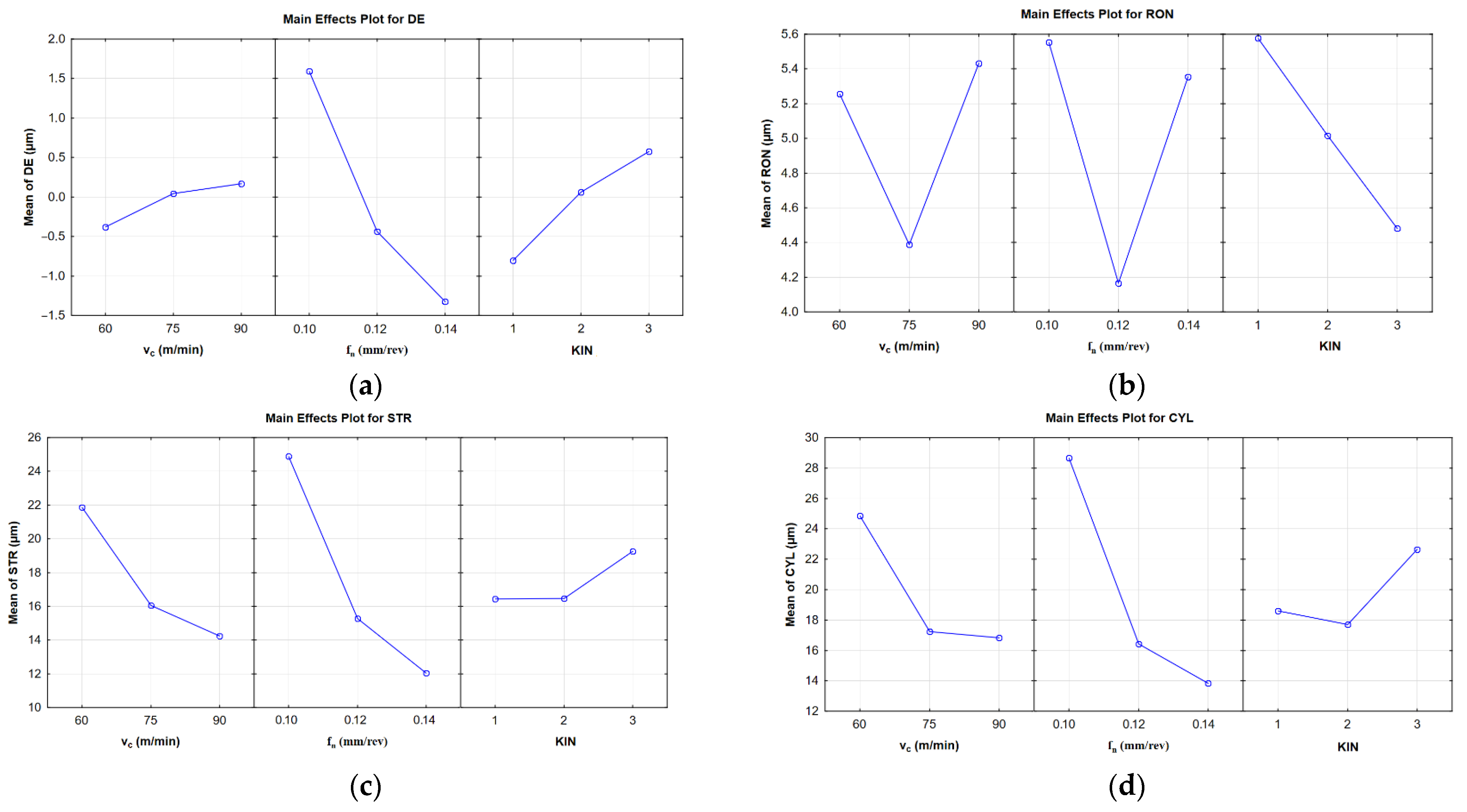
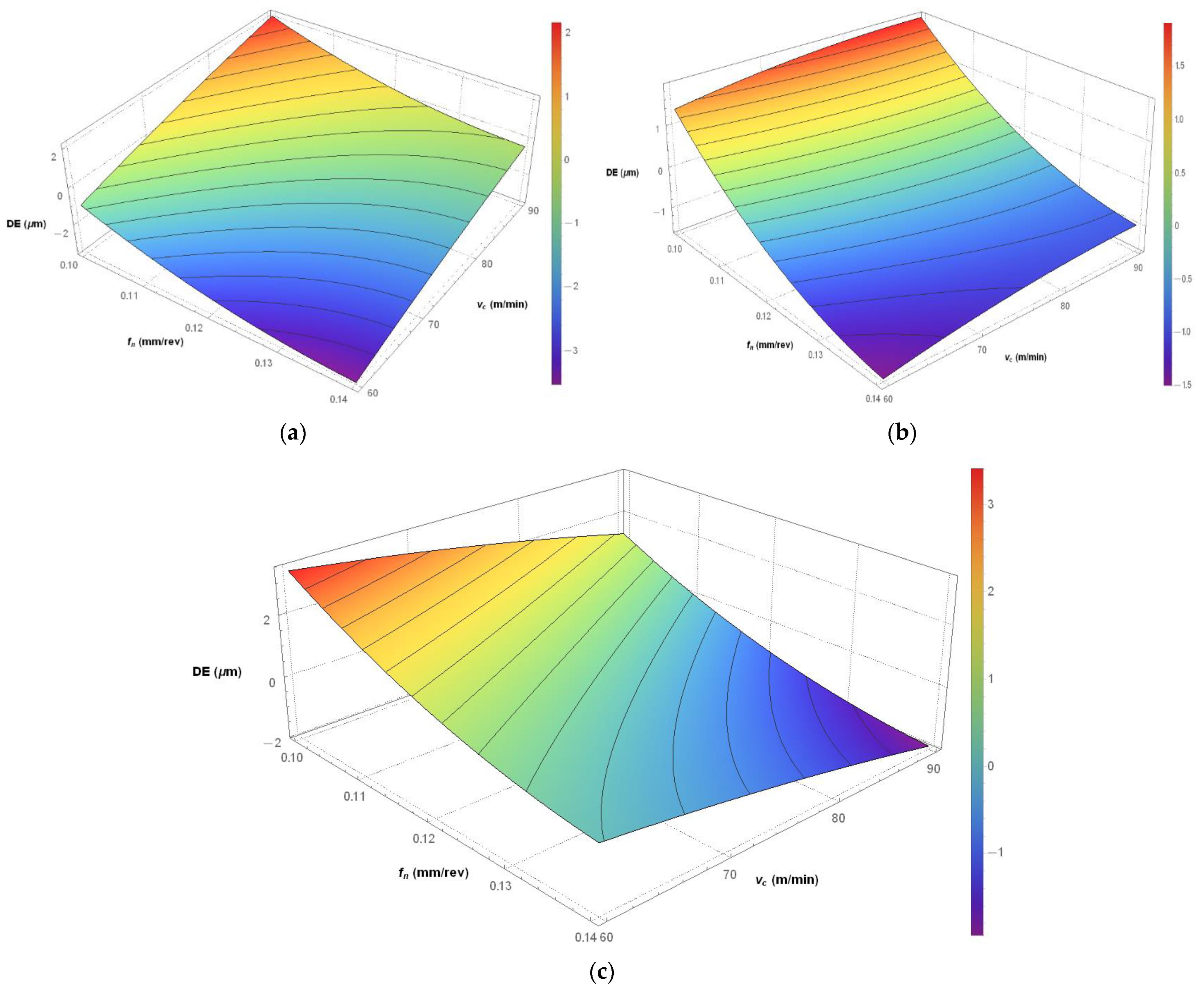
The aim of this study was to determine the influence of the input parameters (KIN, vc and fn) on the output parameters (CYL, STR, RON and DE) for holes drilled in C45 steel. The percentage contribution of each input parameter was assessed using a multifactorial statistical analysis (ANOVA). The mathematical models built for the output parameters were significant (p < 0.05) and the predicted results were in good agreement with the experimental data (R2 > 0.8). The kinematic system was reported to have high influence on the hole diameter error (36.61%). The other output parameters, i.e., CYL, RON, and STR, were largely dependent on the feed per revolution.

2. Materials and Methods

The specific objective of this study was to establish how the type of kinematic system used for drilling C45 steel contributed to the diameter, roundness, straightness, and cylindricity errors of the holes cut. The testing was carried out using a DMG MORI CTX, Bielefeld, Germany, alpha 500 universal turning center with driven tools. Three kinematic systems were used to perform the drilling.
The tool tested was a 5D drill bit coated with titanium aluminum nitride measuring 6 mm in diameter. The drill bit was clamped in an axial drilling and milling head (VDI30, SAUTER 113180, Metzingen, Germany). Its characteristic features include internal coolant supply and external nozzle. The clamping required using an ER25 DIN 5480 collet chuck, Orion, Ludwigsburg, Germany. One new drill bit was used for each kinematic system. Each tool was used to drill 9 holes. No measurable wear was observed on any of the tools.
The material tested—C45 steel (1.0503)—is a non-alloy quality steel suitable for heat treatment. The chemical composition of the material is provided in Table 1.
The material is easy to work, but difficult to weld. It has high flexural strength, high tensile strength, and high ductility. Table 2 shows the main properties of the steel tested.
Figure 1, Figure 2 and Figure 3 show the three kinematic systems used for drilling holes. Figure 1 depicts the first kinematic system (KIN I), where the workpiece is fixed and the tool both rotates and moves linearly.
Figure 2 illustrates the second kinematic system (KIN II), where the workpiece rotates and the tool moves linearly parallel to the workpiece axis of rotation.
Figure 3 presents the third kinematic system (KIN III), where the workpiece and tool rotate in opposite directions; the tool also performs a rectilinear motion.
Twenty-seven cylindrical samples 30 mm in diameter and 30 mm in length were used in the drilling tests. They were prepared by planing and clamped in a 3-jaw chuck. The experiments involved drilling 6 mm axial through-holes. Table 3 shows the input parameters and the setting levels.
The drilling was carried out for all the combinations of the parameters presented in Table 3. Thus, 27 holes were cut.
Table 4 shows the input parameters and the corresponding average values of the diameter, roundness, straightness, and cylindricity errors. The metrological results were obtained by means of a ZEISS PRISMO Navigator, Oberkochen, Germany, coordinate measuring machine. The measurements were taken using a ruby probe stylus ball tip with a radius of 1.5 mm at a speed of 5 mm/s. A total of 1500 measuring points were collected. The measurement strategy, illustrated in Figure 4, was as follows. The cylindricity error was established from roundness profiles using a Gaussian filter at 15 UPR and λc = 2.5 mm. The straightness error was measured along the four generatrixes of the hole, spaced every 90°. The diameter and roundness errors were measured at 5 different planes spaced every 7.5 mm, as shown in Figure 4 and indicated as circles, with ‘Circle 1’ and ‘Circle 5’ being the circles measured at the hole exit and entry, respectively.
The experiment required deriving Taguchi L27 orthogonal arrays for three input parameters each at three levels (3 × 3 × 3). Table 4 shows all the sets of the input parameters with their responses.
Statistical calculations were made on the basis of the Taguchi L27 orthogonal arrays. Statistica software (13.3.721.1) was used for this purpose.

3. Results and Discussions

The statistical calculations helped assess the effects of the input parameters on the selected output parameters. In each statistical analysis, the confidence level was 95% and the significance level was 5%. Table 5 and Table 6 show the ANOVA results for the particular output parameters. The values of MS and SS provided in Table 5 and Table 6 were used to calculate the value of F, which was then checked in the arrays to determine the significance of the statistical analysis. The analysis indicates that the mathematical models developed for the purpose of this research are significant. The values of p were below 0.05, which confirms their significance. As can be seen from Table 6 for the diameter error, the total percentage contribution of the input parameter KIN obtained in the statistical analysis (ANOVA) was 36.61%. The other output parameters were mainly dependent on feed per revolution. For the hole cylindricity error, it was 37.1%. For the straightness error, it reached 30.24%. In the case of the roundness error, the effect of feed per revolution was the highest (81.37%). The mathematical models based on the empirical observations confirm that the correlation between the input and output variables is high (CYL R2 = 0.8827, STR R2 = 0.9384, RON R2 = 0.8584, and DE R2 = 0.8369).
The mathematical models built to predict the diameter, roundness, straightness, and cylindricity errors for the material tested were based on the factorial and polynomial response surface regression model. The predictive models are provided in Equations (1)–(4).
R O N = 81.9167 0.7593 v c + 0.0042 v c 2 8.6236 f n + 0.3208 f n 2 + 2.45 K I N + 0.0167 K I N 2 + 0.0147 v c · f n 0.0222 v c · K I N 0.1167 f n · K I N
D E = 7.1296 + 0.2774 v c 0.0006 v c 2 3.9556 f n + 0.1403 f n 2 + 8.9833 K I N 0.1722 K I N 2 + 0.0006 v c · f n 0.0867 v c · K I N 0.0917 f n · K I N
S T R = 284.8093 2.7704 v c + 0.0089 v c 2 27.7486 f n + 0.7972 f n 2 + 25.9722 K I N + 1.3889 K I N 2 + 0.1186 v c · f n 0.1222 v c · K I N 1.7458 f n · K I N
C Y L = 488.8204 4.8437 v c + 0.0160 v c 2 44.7736 f n + 1.2056 f n 2 + 3.8389 K I N + 2.9222 K I N 2 + 0.1864 v c · f n 0.0322 v c · K I N 0.9250 f n · K I N
where KIN I = 1; KIN II = 2; KIN III = 3.
The main effects plots in Figure 5 show the effects of the cutting speed, the feed per revolution and the kinematic system on the diameter, roundness, straightness, and cylindricity errors. From Figure 5a, it is clear that the diameter error decreased with increasing cutting speed; this error also decreased with increasing feed rate. The best results were observed for KIN II: the hole had an ideal diameter of 6 mm. Figure 5b indicates that the lowest values of the roundness error were obtained at the following process parameters: vc = 75 m/min and fn = 0.12 mm/rev. The worst results concerning the roundness error were reported for KIN I (average error: 5.59 µm), while the best for KIN III (average error: 4.49 µm). In the case of KIN II, the average roundness error was 5.03 µm. Figure 5c indicates that an increase in the process parameters (vc, fn) caused an increase in the average hole straightness error (12 µm for 0.14 mm/rev and 14 µm for 90 m/min). Kinematic systems I and II look similar; for both, the average straightness error was 14.14 µm. However, when KIN III was used, the hole straightness error increased, reaching an average value of 19.15 µm. The same observation was made for the hole straightness error from Figure 5d. The cylindricity error decreased with increasing process parameters (for vc = 90 m/min, the error was 16.89 µm and for fn = 0.14 mm/rev, it was 13.98 µm). Summing up, KIN II had the greatest effect on three out of four output parameters (DE, STR, CYL), which suggests that this kinematic system is the most favorable. However, the hole roundness error was the smallest for KIN III.
Since KIN had the greatest influence on the diameter error (36.61%), as observed in Table 6, the simulations were carried out for each kinematic system to find out how it affected the diameter error.
The hole diameter error for C45 steel was analyzed with regard to three kinematic systems. From Figure 6a, showing the first kinematic system, it is clear that the highest accuracy in diameter (6 mm) was obtained by linearly increasing both process parameters, i.e., cutting speed and feed per revolution. However, the greatest diameter errors (±2 µm) were reported for two sets of the process parameters, i.e., vc = 90 m/min, fn = 0.1 mm/rev and vc = 60 m/min, fn = 0.14 mm/rev. Figure 6b, depicting the second kinematic system, indicates that at the same process parameters, the accuracy was the lowest and the error reached ± 1.5 µm. For this kinematic system, the most desirable diameter error of 0 µm was achieved at a cutting speed ranging from 60–90 m/min and a feed per revolution of 0.11 mm/rev. It is worth mentioning that the cutting speed did not have a considerable effect on the hole diameter error. However, the other process parameter, i.e., the feed per revolution did contribute to the diameter error. The diameter error increased when the feed per revolution increased above or decreased below 0.11 mm/rev. As can be seen from Figure 6c, there is an inverse relationship between the input parameters and the diameter error for the third kinematic system when compared to the first. The greatest error of ± 1.5 µm was obtained for the following two sets of the process parameters: vc = 60 m/min, fn = 0.1 mm/rev and vc = 90 m/min, fn = 0.14 mm/rev. For this kinematic system, a diameter error of 0 µm was obtained by linearly increasing the cutting speed and decreasing the feed per revolution. The research results can be of practical use to industrial engineers as they will be able to select optimal process parameters to drill a hole with a desired dimensional accuracy.

4. Conclusions

The major purpose of this study was to determine how the process parameters as well as the kinematic system used for drilling a hole in C45 steel affected the output parameters such as the diameter, roundness, straightness, and cylindricity errors. The methodology and results described here might be used in practice in the manufacturing sector to optimize the selection of process parameters for hole cutting in this type of steel so that desired values of the hole quality parameters are obtained.
The following are the most important conclusions drawn from the experiment:
  • The four mathematical models developed for this study to analyze hole drilling in C45 steel provide a high correlation between the observed values and the predicted ones (for the diameter error, R2 = 0.84, for the roundness error, R2 = 0.86, for the straightness error, R2 = 0.94, and for the cylindricity error, R2 = 0.88).
  • The type of kinematic system used for drilling in C45 steel is an important factor when the hole diameter is considered.
  • For the diameter error, KIN I is a mirror image of KIN III along the diagonal between the vc and fn axes.
  • Further research will focus on analyzing the influence of the type of kinematic system on the quality of holes drilled in elements of the jet engine exhaust section.

Author Contributions

Conceptualization, M.B., L.N. and E.M.; methodology, M.B. and L.N.; software, M.B.; formal analysis, M.B.; investigation, M.B.; resources, M.B.; data curation, M.B.; writing—original draft preparation, M.B.; writing—review and editing, M.B., L.N. and E.M. All authors have read and agreed to the published version of the manuscript.

Funding

This research received no external funding.

Institutional Review Board Statement

Not applicable.

Informed Consent Statement

Not applicable.

Data Availability Statement

Data sharing is not applicable.

Conflicts of Interest

The authors declare no conflict of interest.

Nomenclature

CYLCylindricity error (µm)
DEDiameter error (µm)
DFDegrees of freedom
DOEDesign of experiment
f n feed per revolution (mm/rev)
KINKinematic system
MSMean square
nspindle speed (rpm)
psignificance
PCPercentage contribution
RONRoundness error (µm)
SSSum of squares
STRStraightness error (µm)
UPRUndulations per revolution
vccutting speed (m/min)
v f feed rate (mm/min)
λcwave length (mm)

References

  1. Kurt, M.; Kaynak, Y.; Bagci, E. Evaluation of drilled hole quality in Al 2024 alloy. Int. J. Adv. Manuf. Technol. 2008, 37, 1051–1060. [Google Scholar] [CrossRef]
  2. Singh, K.P.; Kumar, K.; Saini, P. Optimization of surface roughness and hole diameter accuracy in drilling of EN-31 alloy steel—A TGRA based analysis. Mater. Today Proc. 2020, 26, 2961–2971. [Google Scholar] [CrossRef]
  3. Prasanna, J.; Karunamoorthy, L.; Venkat Raman, M.; Prashanth, S.; Raj Chordia, D. Optimization of process parameters of small hole dry drilling in Ti-6Al-4V using Taguchi and grey relational analysis. Measurement 2014, 48, 346–354. [Google Scholar] [CrossRef]
  4. Aamir, M.; Giasin, K.; Tolouei-Rad, M.; Vafadar, A. A review: Drilling performance and hole quality of aluminium alloys for aerospace applications. J. Mater. Res. Technol. 2020, 9, 12484–12500. [Google Scholar] [CrossRef]
  5. Nowakowski, L.; Skrzyniarz, M.; Miko, E. The analysis of relative oscillation during face milling. Eng. Mech. 2017, 182, 730–733. [Google Scholar]
  6. Nowakowski, L.; Skrzyniarz, M.; Miko, E. The assessment of the impact of the installation of cutting plates in the body of the cutter on the size of generated vibrations and the geometrical structure of the surface. Eng. Mech. 2017, 182, 734–737. [Google Scholar]
  7. Aized, T.; Amjad, M. Quality improvement of deep-hole drilling process of AISI D2. Int. J. Adv. Manuf. Technol. 2013, 69, 2493–2503. [Google Scholar] [CrossRef]
  8. Szwajka, K.; Zielińska-Szwajka, J. Wpływ wybranych parametrów skrawania na dokładność obróbki w procesie wiercenia stopu Ti6Al4V. Zeszyty Naukowe Politechniki Rzeszowskiej Mechanika 2019, 91, 79–92. [Google Scholar] [CrossRef]
  9. Vipin; Kant, S.; Jawalkar, C.S. Parametric Modeling in Drilling of Die Steels using Taguchi Method based Response Surface Analysis. Mater. Today Proc. 2018, 5, 4531–4540. [Google Scholar] [CrossRef]
  10. Kurt, M.; Bagci, E.; Kaynak, Y. Application of Taguchi methods in the optimization of cutting parameters for surface finish and hole diameter accuracy in dry drilling processes. Int. J. Adv. Manuf. Technol. 2009, 40, 458–469. [Google Scholar] [CrossRef]
  11. Çiçek, A.; Kivak, T.; Ekici, E. Optimization of drilling parameters using Taguchi technique and response surface methodology (RSM) in drilling of AISI 304 steel with cryogenically HSS drills. J. Intell. Manuf. 2015, 26, 295–305. [Google Scholar] [CrossRef]
  12. Dheeraj, N.; Sanjay, S.; Kiran Bhargav, K.; Jagadesh, T. Investigations into solid lubricant filled textured tools on hole geometry and surface integrity during drilling of aluminium alloy. Mater. Today Proc. 2020, 26, 991–997. [Google Scholar] [CrossRef]
  13. Angelone, R.; Caggiano, A.; Improta, I.; Nele, L.; Teti, R. Characterization of hole quality and temperature in drilling of Al/CFRP stacks under different process condition. Proc. CIRP 2018, 79, 319–324. [Google Scholar] [CrossRef]
  14. Yoon Par, S.; Jong Choi, W.; Hoon Choi, C.; Soap Choi, H. Effect of drilling parameters on hole quality and delamination of hybrid GLARE laminate. Compos. Struct. 2018, 185, 684–698. [Google Scholar]
  15. Çiçek, A.; Uçak, N. The effects of cutting conditions on cutting temperature and hole quality in drilling of Inconel 718 using solid carbide drills. J. Manuf. Process. 2018, 31, 662–673. [Google Scholar]
  16. Giasin, K.; Hodzic, A.; Phadnis, V.; Ayvar-Soberanis, S. Assessment of cutting forces and hole quality in drilling Al2024 aluminium alloy: Experimental and finite element study. Int. J. Adv. Manuf. Technol. 2016, 87, 2041–2061. [Google Scholar] [CrossRef]
  17. Giasin, K.; Ayvar-Soberanis, S. An Investigation of burrs, chip formation, hole size, circularity and delamination during drilling operation of GLARE using ANOVA. Compos. Struct. 2017, 159, 745–760. [Google Scholar] [CrossRef]
  18. Nouari, M.; List, G.; Girot, F.; Gehin, D. Effect of machining parameters and coating on wear mechanisms in dry drilling of aluminium alloys. Int. J. Mach. Tools Manuf. 2005, 45, 1436–1442. [Google Scholar] [CrossRef]
  19. Bronis, M.; Miko, E.; Nowakowski, L. Analyzing the Effects of the Kinematic System on the Quality of Holes Drilled in 42CrMo4 + QT Steel. Materials 2021, 14, 4046. [Google Scholar] [CrossRef] [PubMed]
  20. Khanna, N.; Agrawal, C.; Gupta, M.K.; Song, Q. Tool wear and hole quality evaluation in cryogenic Drilling of Inconel 718 superalloy. Tribol. Int. 2020, 143, 106084. [Google Scholar] [CrossRef]
  21. Sandeep Reddy, A.V.; Ajay Kumar, S.; Jagadesh, T. The Influence of graphite, MOS2 and Blasocut lubricant on hole and chip geometry during peck drilling of aerospace alloy. Mater. Today Proc. 2020, 24, 690–697. [Google Scholar] [CrossRef]
  22. Jia, Z.-Y.; Zhang, C.; Wang, F.-J.; Fu, R.; Chen, C. Multi-margin drill structure for improving hole quality and dimensional consistency in drilling Ti/CFRP stacks. J. Mater. Process. Technol. 2020, 276, 116405. [Google Scholar] [CrossRef]
  23. Abdelhafeez, A.M.; Soo, S.L.; Aspinwall, D.K.; Dowson, A.; Arnold, D. Burr formation and hole quality when drilling titanium and aluminium alloys. Proc. CIRP 2015, 37, 230–235. [Google Scholar] [CrossRef]
  24. Bertolini, R.; Savio, E.; Ghiotti, A.; Bruschi, S. The effect of Cryogenic Cooling and Drill Bit on the Hole Quality when Drilling Magnesium-based Fiber Metal Laminates. Proc. Manuf. 2021, 53, 118–157. [Google Scholar]
  25. Boughdiri, I.; Giasin, K.; Mabrouki, T.; Zitoune, R. Effect of cutting parameters on thrust force, torque, hole quality and dust generation during drilling of GLARE 2B laminates. Compos. Struct. 2021, 261, 113562. [Google Scholar] [CrossRef]
  26. Shah, P.; Khanna, N.; Singla, A.K.; Bansal, A. Tool wear, hole quality, power consumption and chip morphology analysis for drilling Ti-6Al-4V using LN2 and LCO2. Tribol. Int. 2021, 163, 107190. [Google Scholar] [CrossRef]
Figure 1. First kinematic system.
Materials 14 04568 g001
Figure 2. Second kinematic system.
Materials 14 04568 g002
Figure 3. Third kinematic system.
Materials 14 04568 g003
Figure 4. Measurement strategy.
Materials 14 04568 g004
Figure 5. Main effects plots for (a) the diameter error; (b) the roundness error; (c) the straightness error; (d) the cylindricity error.
Materials 14 04568 g005
Figure 6. Simulations based on Equation (2) developed to predict the hole diameter error for: (a) the first kinematic system (b) the second kinematic system; (c) the third kinematic system.
Materials 14 04568 g006
Table 1. Chemical composition of C45 steel, %.
CMnSiPSCrNiMo
0.42–0.50.5–0.8max. 0.4max. 0.045max. 0.045max. 0.3max. 0.3max. 0.1
Table 2. Properties of C45 steel.
Hardness (HB)Tensile Strength (Rm)Yield Stress (Re)Young’s Modulus (E)
≤229560–850 MPa275–490 MPa198–207 GPa
Table 3. Input parameters and the setting levels.
ParametersSettings
Level 1Level 2Level 3
vc (m/min)607590
fn (mm/rev)0.10.120.14
KIN123
Table 4. Input parameters and the corresponding output values (calculated average values).
Experiment Novc (m/min)fn (mm/rev)KINDEavg (µm)RONavg (µm)STRavg (µm)CYL (µm)
1600.11−2.45.826.835.9
2600.123.06.029.836.6
3600.133.66.444.351.8
4600.121−2.44.820.223.8
5600.122−0.84.417.213.5
6600.1230.64.620.018.6
7600.141−3.05.810.212.1
8600.142−1.75.114.311.8
9600.143−0.34.314.119.7
10750.110.65.217.821.6
11750.121.35.320.122.1
12750.132.74.428.727.2
13750.121−1.34.514.916.3
14750.1220.53.115.619.6
15750.1230.03.314.516.8
16750.141−1.75.114.011.4
17750.142−1.45.210.49.5
18750.143−0.43.48.510.7
19900.113.87.016.817.5
20900.121.35.218.420.4
21900.130.44.721.225.0
22900.121−0.44.410.611.4
23900.122−0.74.711.511.4
24900.1230.63.712.916.5
25900.141−0.57.616.717.5
26900.142−1.06.110.914.4
27900.143−2.05.59.217.4
Table 5. ANOVA results including the percentage contribution (PC) of the process parameters and the type of kinematic system for the cylindricity and straightness errors.
ParameterCylindricity ErrorStraightness Error
SourceSSDFMSF Valuep ValuePCSSDFMSF Valuep ValuePC
Model2042.64979226.961114.20820.000088.271475.7539163.972528.78320.000093.84
Constant586.23581586.235836.69940.000025.33199.01321199.013234.93420.000012.66
vc263.21031263.210316.47740.000811.3786.1040186.104015.11440.00125.48
vc278.0002178.00024.88300.04113.3724.1335124.13354.23630.05521.53
fn302.91021302.910218.96270.000413.09116.34621116.346220.42300.00037.40
fn2139.52301139.52308.73440.00896.0361.0141161.014110.71020.00453.88
KIN1.888011.88800.11820.73520.0886.4200186.420015.16990.00125.50
KIN251.2363151.23633.20750.09112.2111.5741111.57412.03170.17220.74
v c · f n 375.20081375.200823.48820.000216.21151.94081151.940826.67120.00019.66
v c · K I N 2.803312.80330.17550.68050.1240.3333140.33337.08000.01652.56
fn·KIN41.0700141.07002.57110.12731.77146.30081146.300825.68120.00019.30
Error271.55771715.974011.7396.8457175.69686.16
Total2314.2074261001572.598526100
Table 6. ANOVA results including the percentage contribution (PC) of the process parameters and the type of kinematic system for the roundness and diameter errors.
ParameterRoundness ErrorDiameter error
SourceSSDFMSF Valuep ValuePCSSDFMSF Valuep ValuePC
Model25.431992.825811.45200.000085.8471.311197.92359.69470.000083.69
Constant16.4634116.463466.72120.000055.570.124710.12470.15260.70090.15
vc6.467416.467426.21040.000121.830.863310.86331.05630.31851.01
vc25.415015.415021.94540.000218.280.115710.11570.14160.71130.14
fn11.2369111.236945.54010.000037.932.364212.36422.89270.10722.77
fn29.881719.881740.04750.000033.351.889111.88912.31140.14682.22
KIN0.769010.76903.11650.09552.6010.3388110.338812.65000.002412.13
KIN20.001710.00170.00680.93550.010.178010.17800.21770.64670.21
v c · f n 2.340812.34089.48670.00687.900.003310.00330.00410.94980.00
v c · K I N 1.333311.33335.40360.03274.5020.2800120.280024.81350.000123.80
f n · K I N 0.653310.65332.64780.12212.210.403310.40330.49350.49190.47
Error4.1947170.246714.1613.8941170.817316.31
Total29.62672610085.205226100
Publisher’s Note: MDPI stays neutral with regard to jurisdictional claims in published maps and institutional affiliations.

