3.1. Static Tensile Test and Hardness Measurements
Strength tests of the welded joints of Hardox 600 steels have shown that, in the state immediately after welding (process No. 1 in
Table 6), they have an average tensile strength of R
m = 879 MPa. In the context of data provided by the producer (R
m ≥ 2000 MPa,
Table 1), as well as those determined and presented in [
4] and
Table 1 of the actual mechanical parameters of the tested steel, it can be indicated that the obtained index of the static strength of the entire welded joint is only 41–44% of the strength of the base material. It is also worth emphasizing that the discussed strength parameter is obtained at a relatively low level of relative elongation (A
5) and percentage reduction of area (Z), which, in this case, is also associated with a low level of impact toughness, reaching already at ambient temperature a value below a brittleness threshold, often defined by the value 35 J/cm
2 [
27]. The above-mentioned observations lead to the conclusion that properties of the welded joint obtained in the SAW technology in the delivered condition do not meet the basic strength requirements, which, in each case, should be related to the properties of the base material. Additionally, the obtained low impact toughness indices clearly indicate the possibility of fragility fracture, both during operation and at the stage of preparation and implementation of the welded structure (structural weldability). Therefore, according to the author of this study, what is emphasized by the producer of Hardox steel frequently, as well as by many other producers of high-strength steels resistant to abrasion, the classification of this material group in terms of weldability, should be changed (extended). Otherwise, the use of welding processes for them without additional post-operative procedures within the entire heat-affected zone—in relation to the base material—leads to a reduction in mechanical properties, deterioration of resistance to abrasive wear, and increased potential of brittle fracture. The use of quenching and tempering operations after welding (process No. 2 in
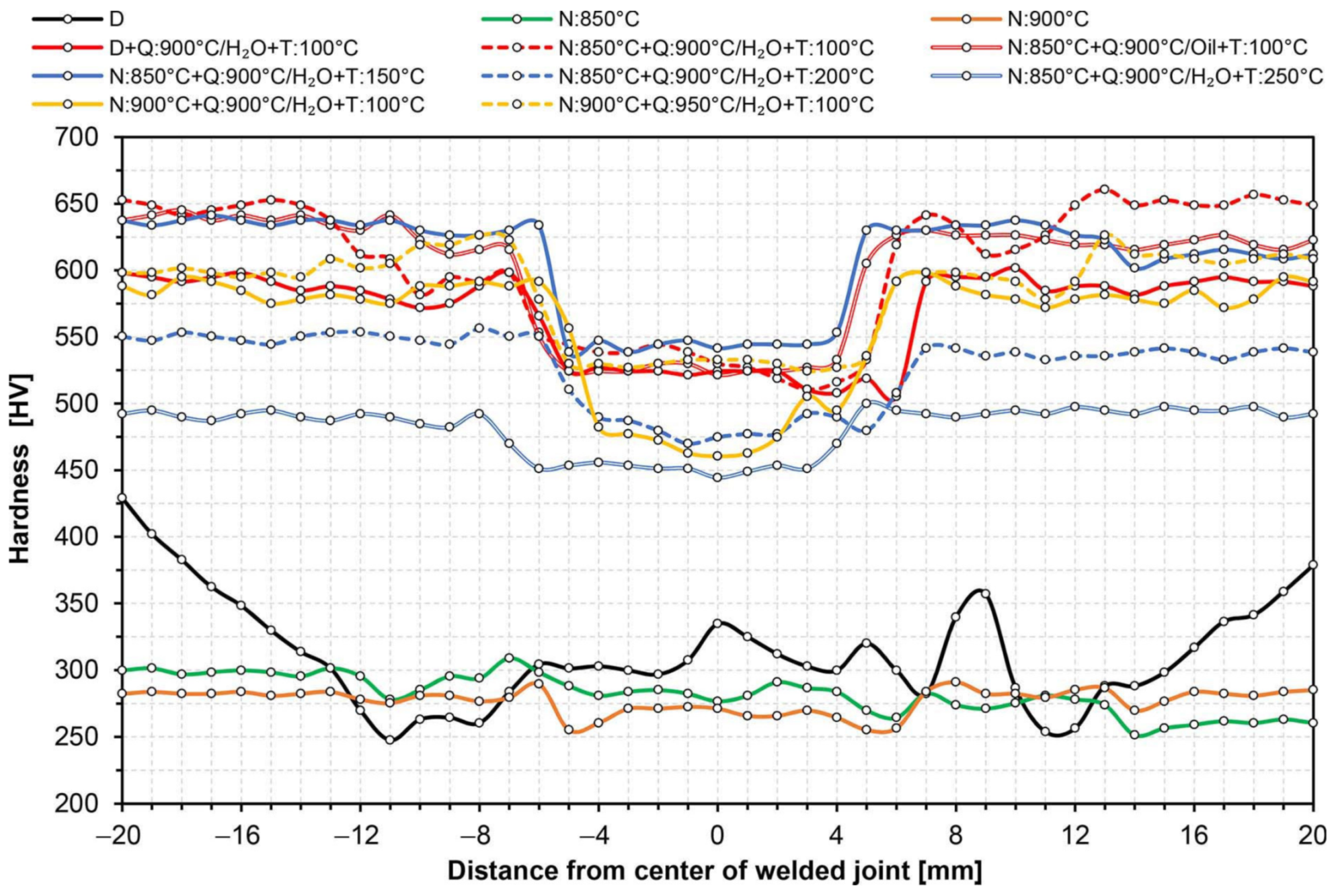
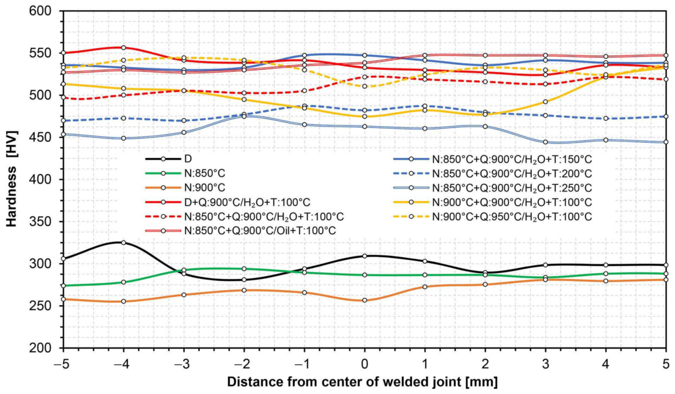
Table 6) against Hardox 600 also did not produce satisfactory results. Subjecting the entire heat-affected zone to the above-mentioned treatments leads to the reconstruction of hardness levels within the welded joint (
Figure 10 and
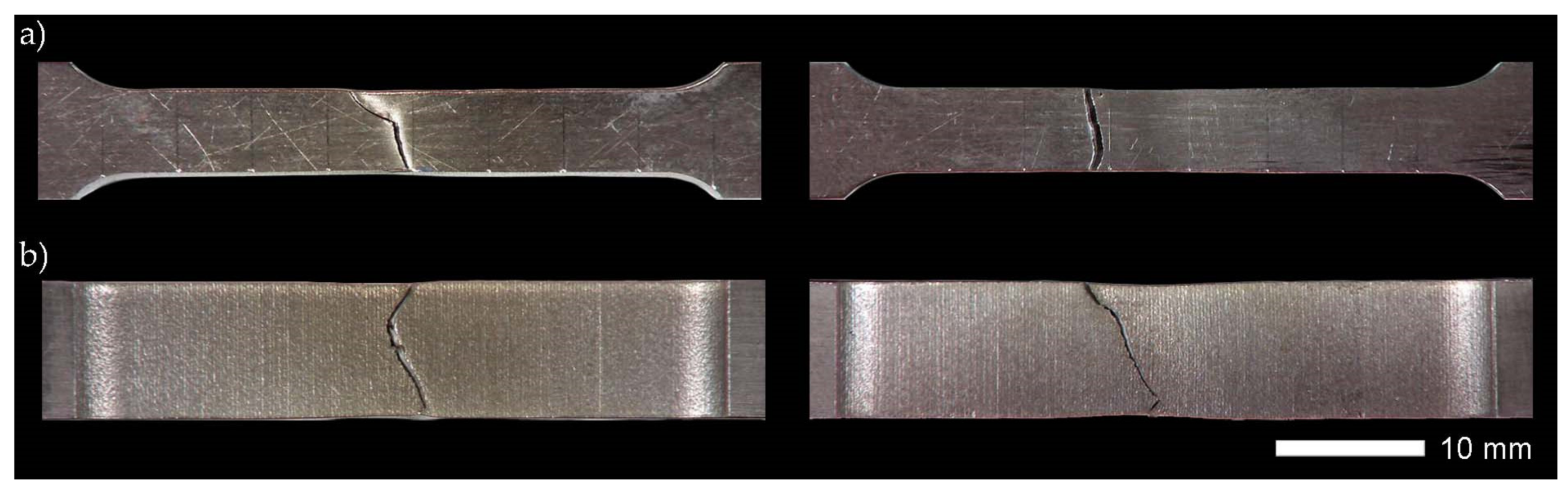
Figure 11); nevertheless, despite a significant increase in the elastic limit and plastic extension, in virtually every test of the test procedure, it was subjected to brittle fracture before reaching the theoretical tensile strength. The immediate reasons for this were numerous discontinuities in the micro-structure observed throughout a fusion line, impossible to be leveled without additional thermal treatments prior to quenching.
Taking into account the previously described problems of reduced mechanical and functional properties of welded joints of the analyzed steel, it seems reasonable to use before-quenching, normalizing annealing operations or technological operations to enable regulated cooling after austenitizing. From a scientific point of view, the use of uniform annealing treatments should also be considered. Such treatment, however, most often requires long-term isothermal annealing in conditions of a strongly overheated austenitic phase. In addition, it largely eliminates the influence of multiple re-crystallization and phase crushing of steel sheets obtained in the course of thermomechanical rolling, and therefore makes it impossible—from a practical approach to the problem—to restore structural and strength properties of the base material.
Table 6 presents the results of strength tests of welded joints of Hardox 600 steel, subjected to normalizing annealing, carried out at the temperature of 850 °C (process No. 3) and 900 °C (process No. 4). In both cases, obtained mechanical properties and hardness distributions (
Figure 10 and
Figure 11) were almost identical and corresponded very well with the parameters of the welded joint as delivered. In relation to the latter, the normalization operations clearly led to homogenization of the micro-structure of entire heat-affected zone and the base material, at the same time translating into an increase in plastic properties by about 19–40% in the case of elongation (A
5) and 80–83% in the case of a percentage reduction of the area (Z). Due to the obtained favorable mechanical and structural properties (considered in a separate part of the manuscript), it seems most justified to analyze the subsequent variants of thermal treatments performed, including the normalizing annealing operation. It is also worth mentioning that, in the discussed case, no impact tests were carried out. This is due to the fact that, in the case of Hardox 600 steel, the use of normalization as the final heat treatment leads to a reduction in fracture toughness, resulting from high activity of precipitation processes during relatively slow cooling. Therefore, according to the author, the use of normalizing annealing treatments as a separate process should not be considered at all. On the other hand, very favorable phenomena in the case of the application of technological operation in question are observed in complex thermal treatments of welded joints, including final quenching and possible tempering.
On the basis of the above considerations,
Table 6 summarizes the results of research on the mechanical properties of several temperature–time variants of complex heat treatments of a welded joint of Hardox 600 steel, taking into account the normalizing annealing operation (processes 4–11).
Figure 10 and
Figure 11 also present hardness changes for all heat treatment schemes listed in
Table 6. On the basis of the obtained test results, it can be concluded that the highest level of strength was obtained with the use of volumetric quenching in water or oil and then tempering at the temperature of 100 °C (processes 5, 9, 11). In all three cases, the obtained value of static strength exceeded 1800 MPa while maintaining satisfactory plastic properties. Regardless of this, it is worth pointing out that the application of a higher austenitizing temperature before quenching in a water bath (process 11) increases the plastic extension of the welded joint. However, it should be noted that obtaining high strength indices of the samples, heat-treated in accordance with the presented diagrams, depends on carrying out the normalizing annealing process in a slightly lower—compared to quenching—temperature range. Otherwise, the results will not be satisfactory (process 10). This is due to the fact that, during the normalization, as well as in an initial cooling stage after this process, complex precipitation processes occur in steel, resulting in the depletion of austenite in carbon and, thus, a lower degree of supersaturation of a solid solution with this element during the quenching operation. A detailed explanation of this phenomenon required numerous studies with the use of X-ray electron microscopy (TEM), which, due to the very extensive nature of the discussed issues, require a separate study. It is worth adding, however, that a similar effect is also observed in other micro-alloyed steels with chemical compositions and functional properties similar to Hardox 600 steel. On the other hand, referring to the value of the required quenching temperature, the author’s experience shows that, in the normalizing temperature range 850–900 °C, increasing the quenching temperature by 50 °C allows for obtaining of optimal heat treatment conditions for the welded joint of the tested steel, ensuring high mechanical properties.
The above considerations regarding the possible strength properties of a welded joint of Hardox 600 steel, subjected to comprehensive heat treatments, should be additionally supplemented with the aspect of increasing the susceptibility to fracture within the base material, observed during numerous research tests. Due to the metallurgical properties of Hardox 600 steel (very high hardenability) and the technology of producing sheets from this steel (thermomechanical rolling), in most cases, the use of a water bath during quenching led to cracks in the axis of the sheet running in the direction of its plastic processing. The appearance of cracks was most often observed after 24–48 h from the quenching process completion. It should also be added that this process was not dependent on the austenitizing temperature before quenching, the tempering temperature or the time interval between quenching and tempering. The described phenomenon was dictated only by a cooling intensity factor during quenching treatments. Therefore, the optimal—from the technological point of view—scheme of thermal treatments in relation to the analyzed welded joint of Hardox 600 steel should be considered: normalization at 850 °C, quenching in oil (heated to a temperature of ~50 °C) and tempering (stress relieving) at 100 °C (150 °C) (process No. 9 in
Table 6). Therefore, further considerations on the structural properties of the welded joint of the tested steel were limited to a delivery condition and to a condition after quenching in oil. It is also worth adding that the application of the above heat treatment scheme also allows—apart from the optimal parameters of the heat-affected zone—restoration of the structural and strength properties of the base material.
Table 6 (the process marked as BM) presents the results of testing the strength and impact properties of the base material samples made of Hardox 600 steel, subjected to heat treatment analogous to those described above. In terms of mechanical properties, heat-treated samples of the base material, apart from a slightly lowered yield strength (R
p0.2), showed almost identical parameters as samples taken from Hardox 600 steel in the smelting condition (
Table 1). Accordingly, the heat treatment scheme No. 9 can be considered optimal, both in relation to the entire heat-affected zone of the welded joint and in relation to the base material.
3.2. The Results of Microscopic Examinations
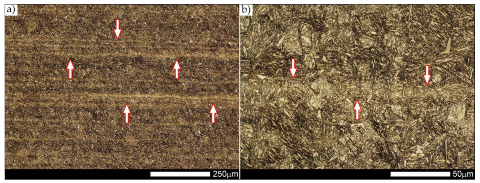
Figure 12 shows an image of the micro-structure of Hardox 600 steel before the welding processes—as delivered. In such a state, the tested steel is characterized by a fine-lath tempering martensite structure with numerous features of a banding structure. These bands are created by the quenching martensite and are the result of thermo–mechanical rolling at the stage of producing Hardox steel sheets. The martensitic structure obtained in the course of metallurgical procedures is characterized by fine needle-like and fine-lath morphology, locally—within the boundaries of the former austenite grains—arranged in the form of characteristic blocks and packages.
Figure 13,
Figure 14,
Figure 15,
Figure 16,
Figure 17,
Figure 18,
Figure 19,
Figure 20,
Figure 21,
Figure 22,
Figure 23,
Figure 24,
Figure 25,
Figure 26,
Figure 27,
Figure 28,
Figure 29,
Figure 30,
Figure 31,
Figure 32,
Figure 33,
Figure 34,
Figure 35 and
Figure 36 show macroscopic images and an overview of characteristic micro-structures of the welded joint of Hardox 600 steel, both as delivered and after selected heat treatment. Immediately after welding (
Figure 13,
Figure 14,
Figure 15,
Figure 16,
Figure 17,
Figure 18,
Figure 19 and
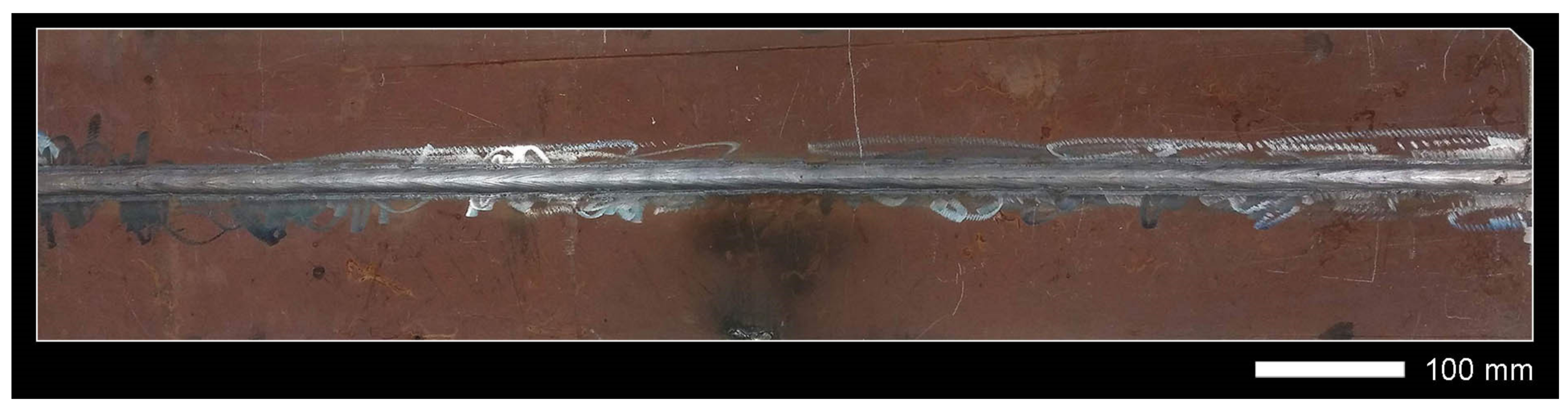
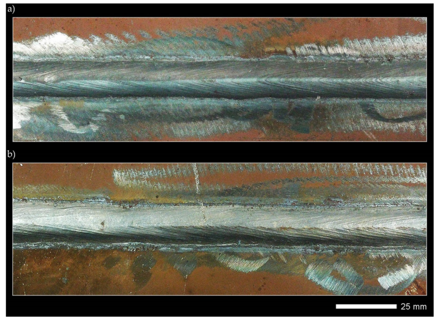
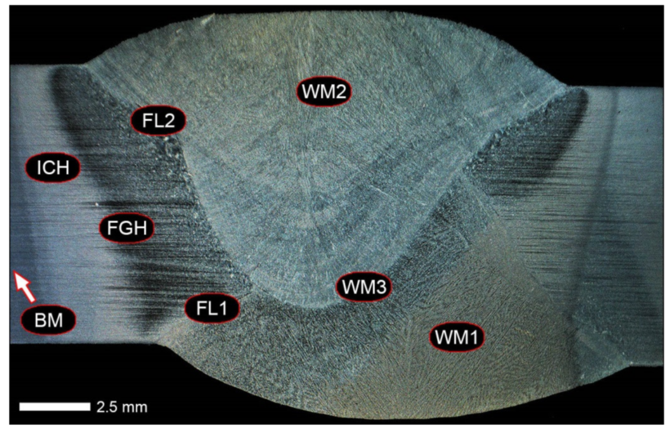
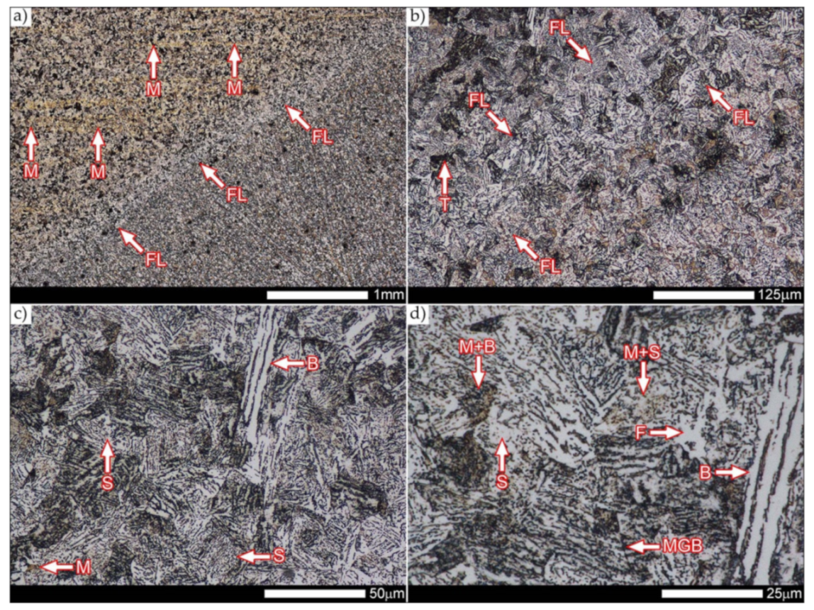
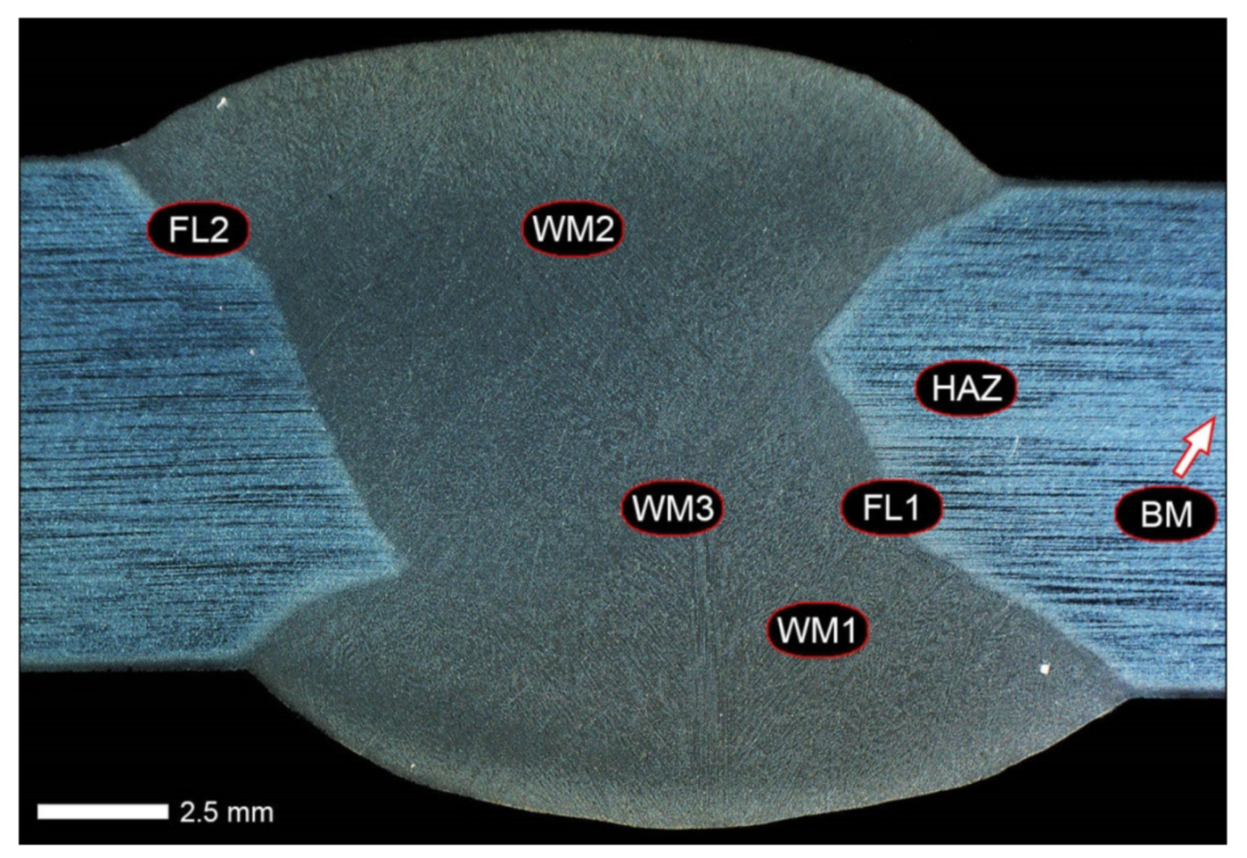
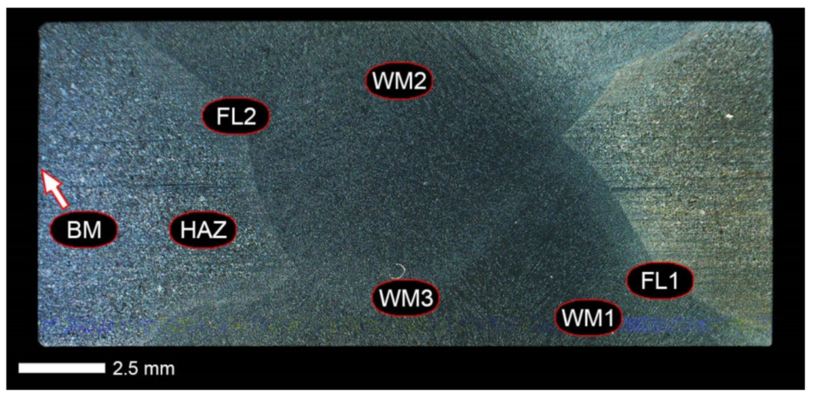
Figure 20), the entire area of the wide heat-affected zone is characterized by very diverse structural changes. The macroscopic image (
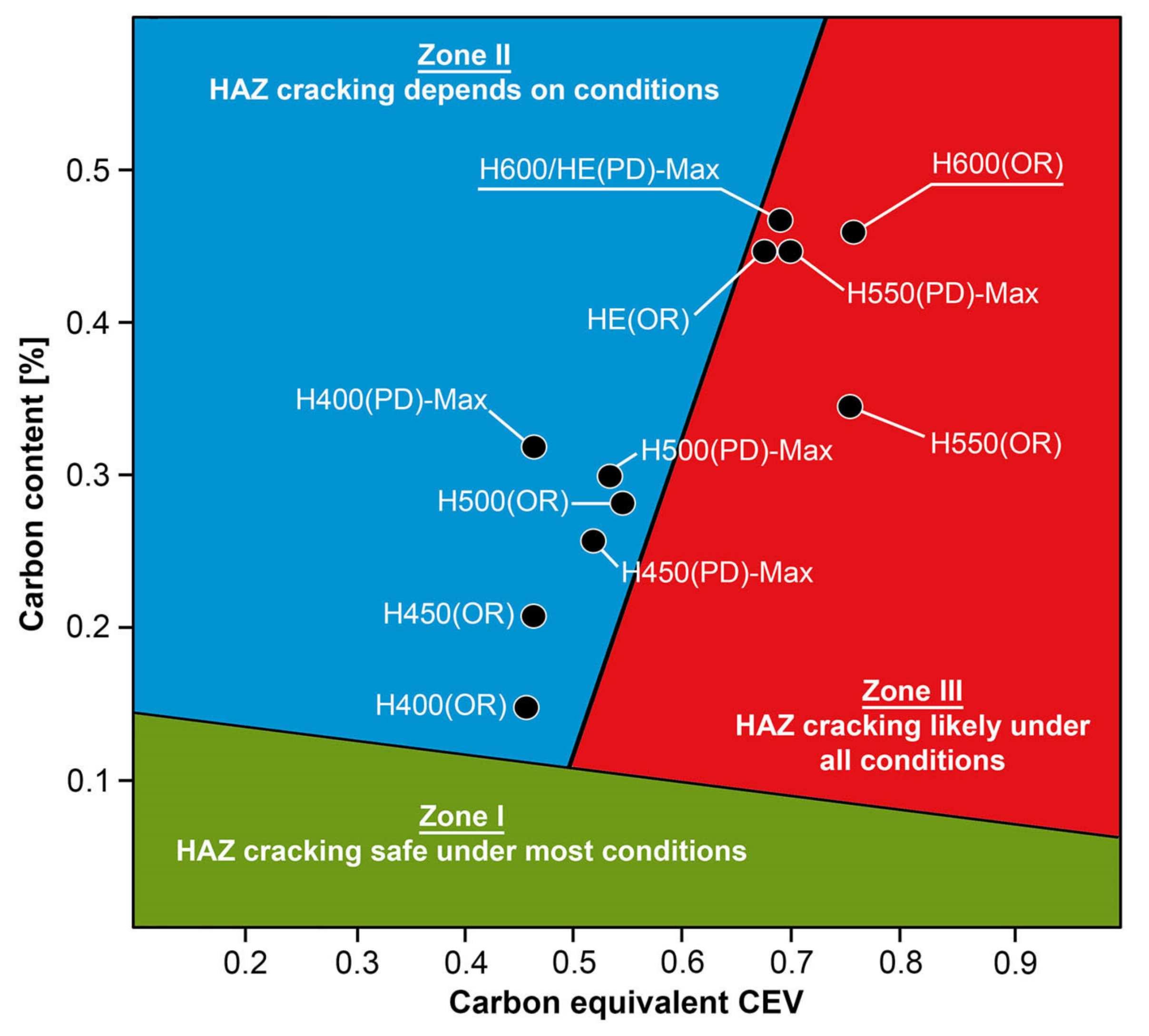
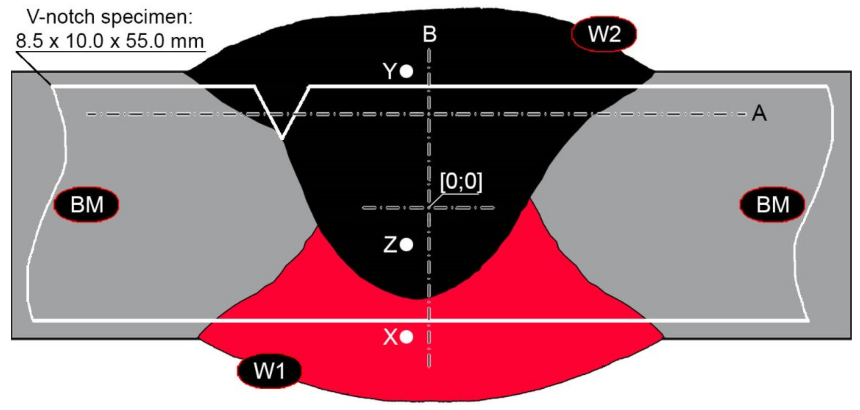
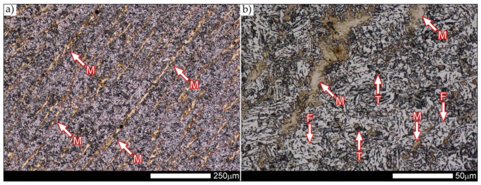
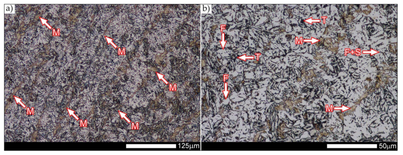
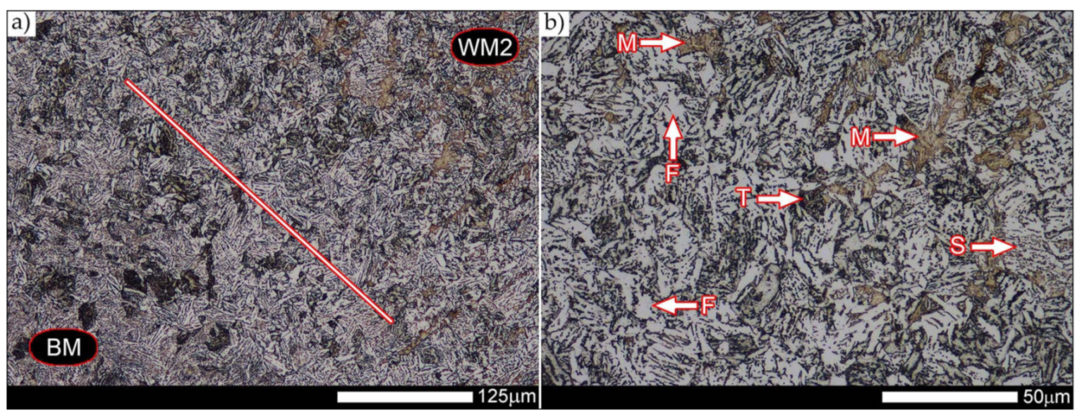
Figure 13) shows selected zones of the tested steel welded joint, which were subjected to a broader micro-structural analysis in the further course of this study. In the zone of the weld metal, which was made in the first place (area WM1 in
Figure 13), the structure of non-equilibrium ferrite is observed in places with precipitations of the quenching troostite (
Figure 14). On the other hand, no clearly visible pearlite colonies are observed, the presence of which may result from the carbon content in this zone, i.e., 0.30% (point X in
Figure 3 and
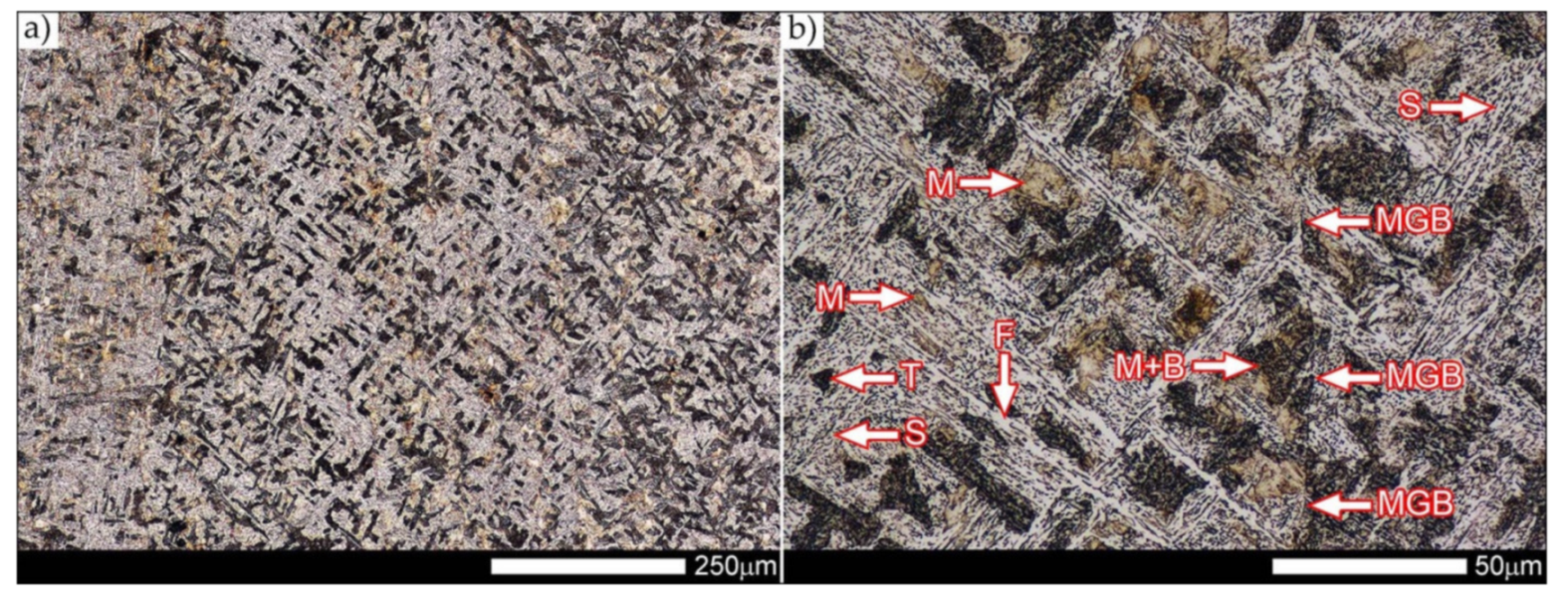
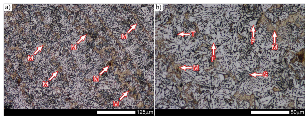
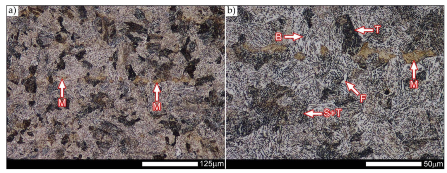
Table 5). In the zones with increased carbon content, band-like precipitation of quenching martensite is observed, proceeding in the direction of crystallization during solidification of the weld metal. Due to the lack of clear features of the dendritic structure, it can be indicated that the considered zone of the welded joint underwent re-crystallization as a result of thermal processes occurring during welding the second layer of the weld. As a result of this treatment, in the zone of the weld metal marked as WM2 in
Figure 13, features of the dendritic structure with numerous precipitates of the quenching structures can be clearly observed (
Figure 15). In general, it consists of quench sorbite—locally, with the characteristics of upper bainite with block ferrite precipitates—as well as numerous regions of martensite or lower bainite, crystallized due to supercritical cooling conditions. In this zone, it is also possible to indicate the presence of wide-angle migration boundaries (
Figure 15b), the presence of which indicates a zonal excess of heat during crystallization from the liquid phase or a reheating cycle, i.e., during the execution of successive layers or weld beads [
28]. It can be concluded that the structural changes observed in the WM2 zone significantly differ from those observed in the WM1 zone, despite the presence of very similar chemical compositions of the weld metal in both zones (point Y in
Figure 3 and
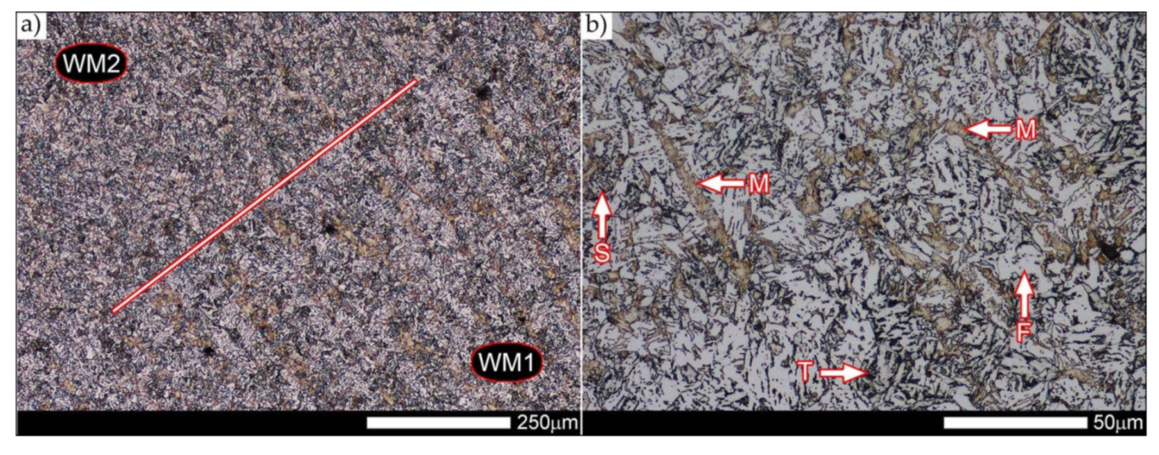
Table 5). The above considerations are confirmed by a construction of a transition zone between WM1 and WM2 (point Z in
Figure 3 and
Table 5). The structural structure of the very clearly delineated zone marked as WM3 in
Figure 13 consists mainly of quenching sorbite—formed along the fusion line of both layers of the weld (
Figure 16). Moreover, in the discussed zone, one can also observe the presence of a martensitic or martensitic–bainitic structure, as well as few colonies of the quenching troostite, most often coexisting with the martensitic areas.
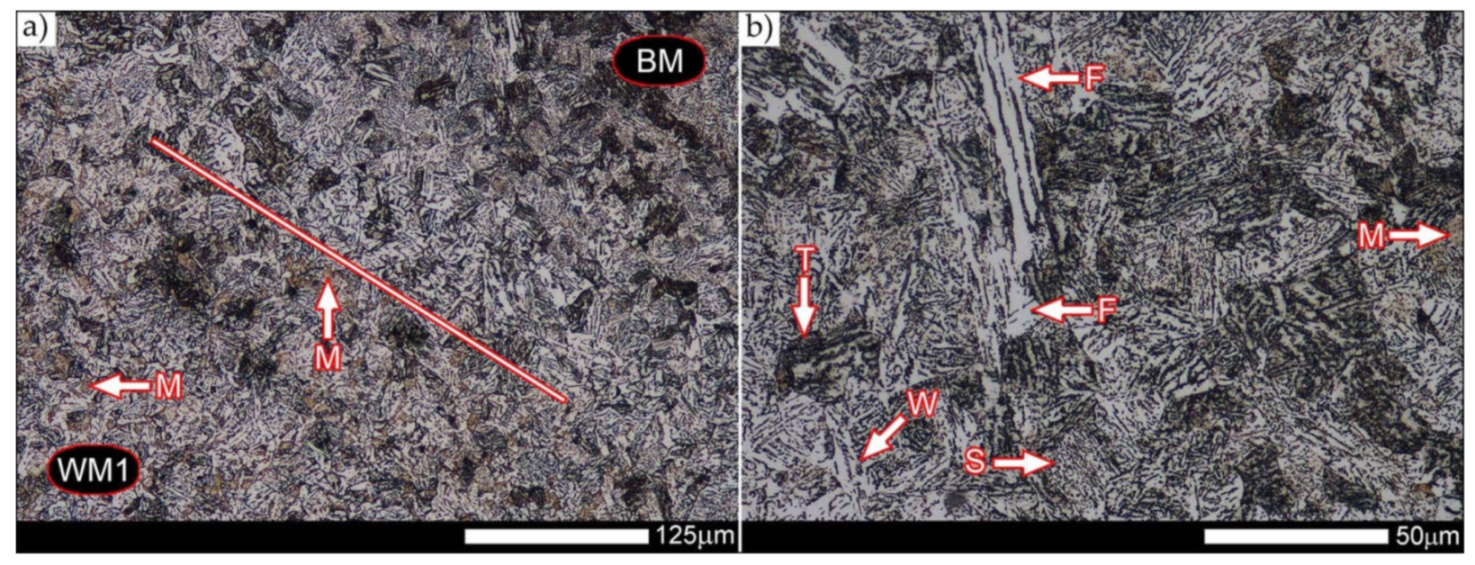
Figure 17 shows structural changes within the fusion line occurring during the execution of the first layer of the weld (FL1 area in
Figure 13). In the case of the above zone, it can be stated that it is dominated by a sorbitic structure with distinct features of post-martensitic orientation. This state of affairs indicates thermal processes that are characteristic of tempering within a fusion line. The regions of martensite or lower bainite in the discussed zone are observed relatively sparse, which seems to confirm the earlier statement. On the other hand, the presence of bainitic ferrite plates (designation B in
Figure 17c,d), thickness of which is 3–5 µm (length ~60 µm), is slightly more numerous. The presence and large size of this phase indicates local (heterogeneous) growth of austenite during welding and also indicates a possibility that, during crystallization of this zone, phase transformations could take place in isothermal conditions. The type of structure described above, in relation to the heat-affected zone of welded joints, most often manifests itself in a significantly reduced brittleness threshold, observed even at ambient temperature.
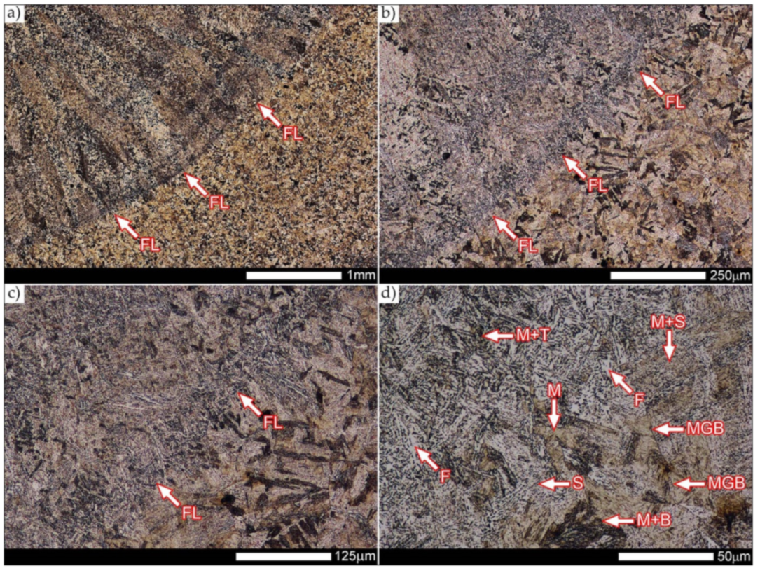
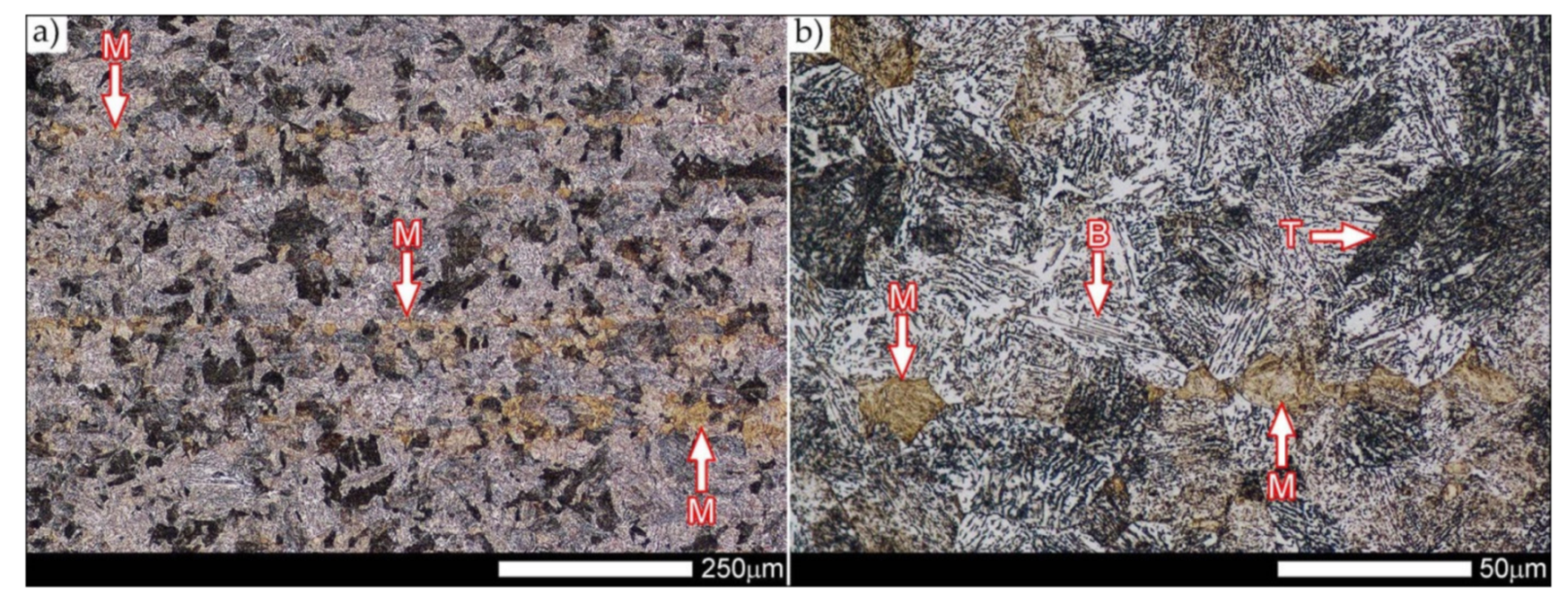
In the case of the zone of the tested welded joint marked as FL2 in
Figure 13, it can be stated that it consists predominantly of a ferritic–sorbitic structure and a strip-like arrangement—in the direction of crystallization—of quenching martensite (
Figure 18). Secretions of lower bainite and troostite are also locally observed. The lack of clear features of the post-martensitic orientation of the sorbite formed and a fairly significant amount of block ferrite allow us to conclude that the pattern of changes taking place on the fusion line during the execution of the second layer of the weld was characteristic of those observed during partial or isothermal quenching. The described type of construction on the fusion line may also indirectly result from the dendritic structure remaining after directional crystallization, which, in the FCC or BCC crystal lattices, most often runs along the <100> direction [
28]. High rate of crystal growth is also associated with a high dendritic segregation index of the chemical composition. Hence, very often on the fusion line of welded joints and surfaced layers there are observed structures indicating lower carbon content than it would result from the chemical composition of the base material and an additional material used. Regardless of the above considerations, due to the presence of migrated grain boundaries (
Figure 18d), it can be concluded that there is a significant excess of heat resulting from the supplied linear energy during welding. This state of affairs was dictated by the welding technology used and the thickness of the Hardox 600 sheet used. It is also worth mentioning that, due to very high martensitic hardenability of the welded steel and the presence of alloy micro-additives preventing the growth of austenite grain, no clear features of Widmanstätten structure are observed in the fusion zone.
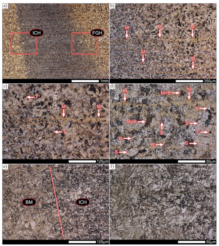
Figure 19 presents a summary of structural changes occurring in selected areas of the heat-affected zone, located outside the weld metal and the fusion lines of individual layers of the weld. In the area marked as FGH in
Figure 13, the presence of different structures, characteristic of the quenching process or—directly in relation to Hardox 600—normalization, was demonstrated (
Figure 19b–d). They include significant amounts of martensite or lower bainite, distributed in strips in the direction of thermoplastic processing of the sheet, as well as areas of quenching sorbite. The presence of a few troostite colonies, areas of upper bainite and structurally free ferrite can also be distinguished.
Figure 19e,f presents the inter-critical heat-affected zone of the welded joint, marked as ICH in
Figure 13. Unlike the FGH zone, the ICH zone is characterized by the presence of structural changes resulting from a tempering process. In general, it can be concluded that it includes a structure characteristic of tempering sorbite with sparse troostite colonies. On the other hand, the structure of the base material (area BM in
Figure 13) can be characterized as tempering martensite with areas of quenching martensite (
Figure 20). Moreover, in the structure of the zone in question, slight banding features, resulting from steel production process, can be indicated.
The above-described structural changes within the entire welded joint of Hardox 600 steel in the delivered condition lead to the conclusion that shaping mechanical and functional properties of this material, resulting only from the technology, welding parameters and conditions used, can be implemented to a very limited extent. The technological trials undertaken, consisting in the re-quenching of selected fragments or the entire heat-affected zone, without the use of other thermal treatments, did not produce satisfactory results. Despite the reproduction of high hardness levels and selected strength parameters, it was not possible to obtain optimal plastic properties and, above all, impact toughness. Therefore, according to the author, implementation of the above objectives is not possible without standardizing structural changes within the selected zones of the welded joint prior to subsequent thermal treatments, e.g., volumetric or surface quenching.
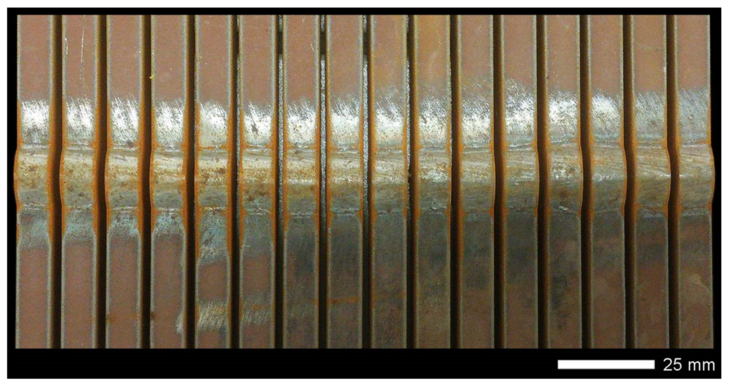
Figure 21 shows a macroscopic image of the considered welded joint after performed normalizing annealing. In such a state of heat treatment (immediately after welding), the same zones of the welded joint were subjected to structural analysis as in the case of the delivered condition. Nevertheless, due to high degree of uniformity of the structure in the area between the FL1/FL2 fusion lines and the base material BM (
Figure 21), in relation to this zone, the tests were generally carried out for the entire heat-affected zone (HAZ designation in
Figure 21).
In the zones of the weld metal, marked as WM1 and WM2 in
Figure 21 (in terms of chemical composition, points X and Y in
Figure 3 and
Table 5), the normalization procedure caused very similar structural changes (
Figure 22 and
Figure 23). In both cases, the obtained structure was characteristic of incomplete quenching treatments. It consisted mainly of non-equilibrium ferrite grains, locally with the features of upper bainite, with a significant volume of a quenching sorbite structure. The presence of a martensitic structure is observed in the carbon-enriched zones, in the form of micro-structural bands running in the direction of weld crystallization during welding. In a few zones, the presence of the quenching troostite structure can also be indicated.
The transition zone between the materials of the weld metal WM1 and WM2 (in terms of chemical composition, point Z in
Figure 3 and
Table 5), marked as WM3 in
Figure 24, in terms of the phase structure, shows great similarities to the zones discussed above. On a very poorly outlined fusion line (
Figure 24a), the presence of a non-equilibrium ferrite structure as well as sorbite and quenching troostite (
Figure 24b) can be indicated. In contrast to WM1/WM2 weld deposit zones, in the WM3 zone, band precipitation of martensitic areas occurs rather sporadically. On the fusion line of this zone, the presence of quenching martensite shows an island character, which proves the re-crystallization of this area as a result of welding and the performed normalizing annealing. It is also worth pointing out that the use of normalization after the welding process does not remove the banding features of the material, formed in metallurgical conditions in the course of thermomechanical rolling.
Figure 25 and
Figure 26 show images of the micro-structure of a welded joint in the normalized state, i.e., on the fusion lines of the weld No. 1 and 2 with the base material, marked as FL1 and FL2, respectively, in
Figure 21. In terms of structural, both zones show quite significant differences from each other. The micro-structure of the rather poorly indicated FL1 fusion line (
Figure 25) can be described as characteristic of isothermal quenching. It mainly consists of sorbite and quenching troostite with relatively few martensitic regions. In the discussed area, it is also possible to indicate the presence of large-size bainitic ferrite plates (not re-crystallized after welding), the length of which exceed 50 μm (
Figure 25b). The mechanism of the formation of this type of structure was outlined in the discussion of structures immediately after welding. It is worth adding, however, that structures of this type are most often much more resistant to tempering processes than typical quenching structures. Therefore, their presence is very often observed in the micro-structure of welded joints, even after normalization procedures have been performed. Moreover, the presence of very few areas with Widmanstätten structure features (designation W in
Figure 25b) may also indicate high overheating during welding of the considered zone.
In the case of the zone marked as FL2 (
Figure 26), it can be stated that in the normalized state it is characteristic of the state after incomplete quenching, and, in terms of structure, it is very similar to the WM3 zone. The zone of weakly outlined fusion line (symbolically marked in
Figure 26a) mainly consists of non-equilibrium ferrite grains, as well as quenching sorbite and quenching troostite. Directly on the fusion line, practically no precipitation of the martensitic structure, which has a much larger share in the zones deeper towards the weld metal, is observed. The discussed type of structure primarily results from the significant dendritic segregation of the chemical composition during welding.
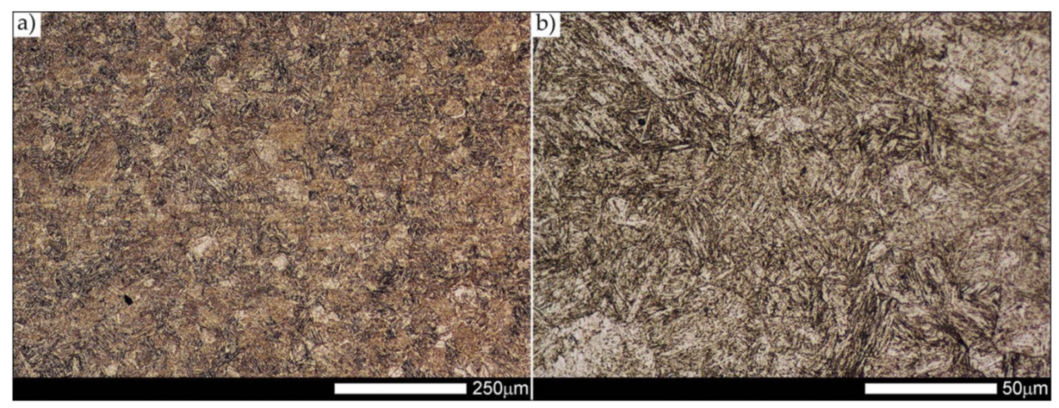
The heat-affected zone subjected to normalization and the zone of the base material, marked in
Figure 21 as HAZ and BM, respectively, are very similar to each other. They are characterized by a fairly diversified structure, characteristic of a hardened state isothermally (
Figure 27 and
Figure 28). In both cases, their structure consisted mainly of quenching sorbite and quenching troostite, as well as band precipitation of the martensitic structure, in many cases transforming into a bainitic structure (
Figure 27b and
Figure 28b). It is worth noting that, both in the HAZ and BM zones, precipitations of the structurally free ferritic phase practically do not occur. This indicates optimal cooling conditions for both zones, resulting from similar chemical composition and the applied heat treatment parameters.
Figure 29 shows a macroscopic image of a welded joint of Hardox 600 steel after comprehensive heat treatment, according to the diagram No. 9 shown in
Table 6. As in the previous cases (as delivered and normalized), the welded joint was subjected to structural tests in selected zones, symbolically marked in the macro-photograph, below.
Figure 30,
Figure 31,
Figure 32,
Figure 33,
Figure 34,
Figure 35 and
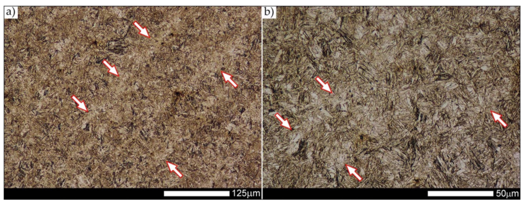
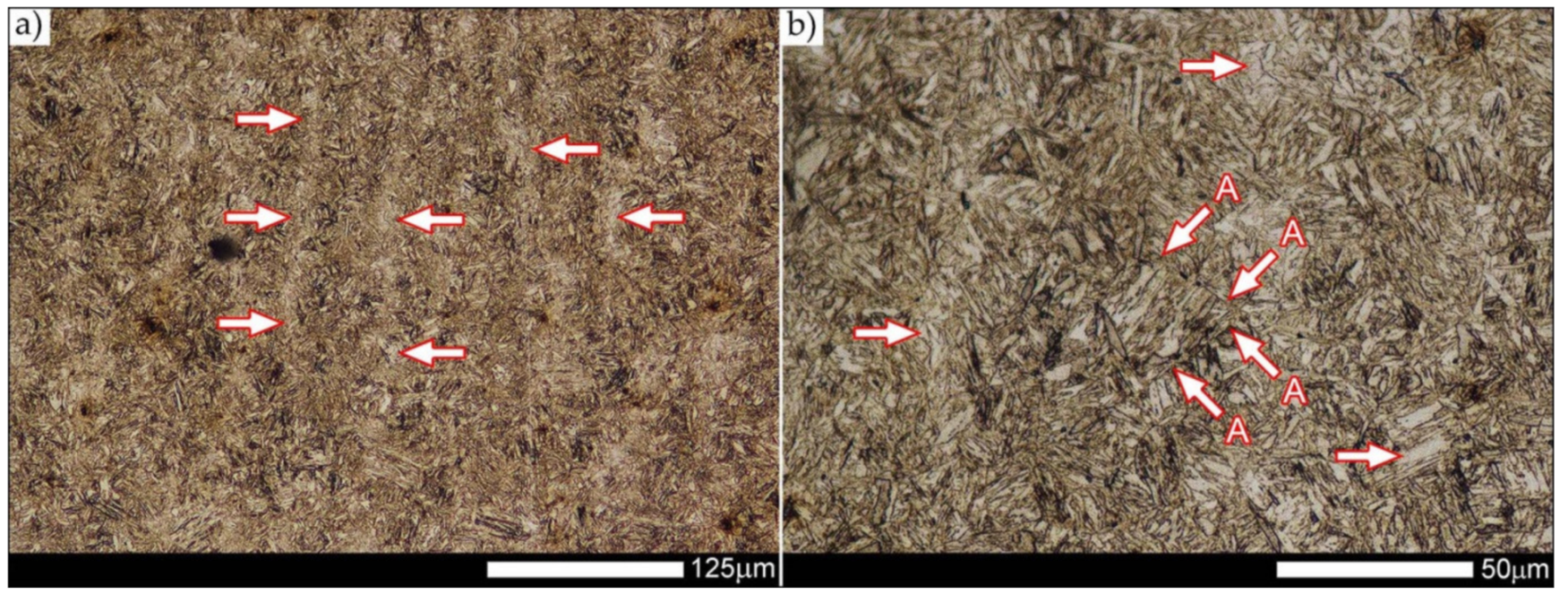
Figure 36 present an overview of the structural structure in the characteristic zones of the tested welded joint. Regardless of the zone under consideration, it can be stated that the implemented thermal treatments caused very similar structural changes in the entire area of the butt weld. In practically every case under consideration, the welded joint was characterized by a fine-lathed tempering martensite structure with areas of quenching martensite. The above statement seems to be correct both for the zone of the base material and the weld metal and for the structural properties observed on the fusion lines.
The weld metal zones marked as WM1 and WM2 presented in
Figure 30 and
Figure 31 show almost identical structural features, which is largely due to the same chemical composition in these areas (points X and Y in
Figure 3 and
Table 5). In both cases, it consists of fine-lath tempering martensite with banded quenching martensite—untempered martensite. These bands run in the direction of the primary crystallization of the weld, caused by the welding process. Locally, apart from these bands—in the zones depleted in carbon—martensite with a packet and block structure is observed, characterized by a low variability of the crystallographic orientation of individual packets within the boundaries of the former austenite grains (arrows A in
Figure 31b). This condition is typical of hardened low-carbon steels.
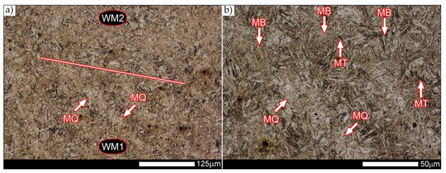
A slightly larger volume of the block martensite structure can be indicated on the fusion line between the weld metal materials (
Figure 32). Almost along the entire length of the very poorly defined fusion line, marked as WM3 in
Figure 29 (in terms of chemical composition, point Z in
Figure 3 and
Table 5), the presence of low-carbon, fine-lath block martensite is observed (MB designation in
Figure 32b). This state of affairs is dictated by the depletion of this area in carbon, resulting in reduced hardenability and resistance to tempering processes. Hence, in sporadic cases, the presence of highly tempered structures with post-martensitic orientation is noted (marking MT in
Figure 32b). It is worth mentioning that removal of the described changes would require additional homogenizing annealing, which, due to the properties of the base material, is inadvisable, as well as technologically difficult and economically unjustified.
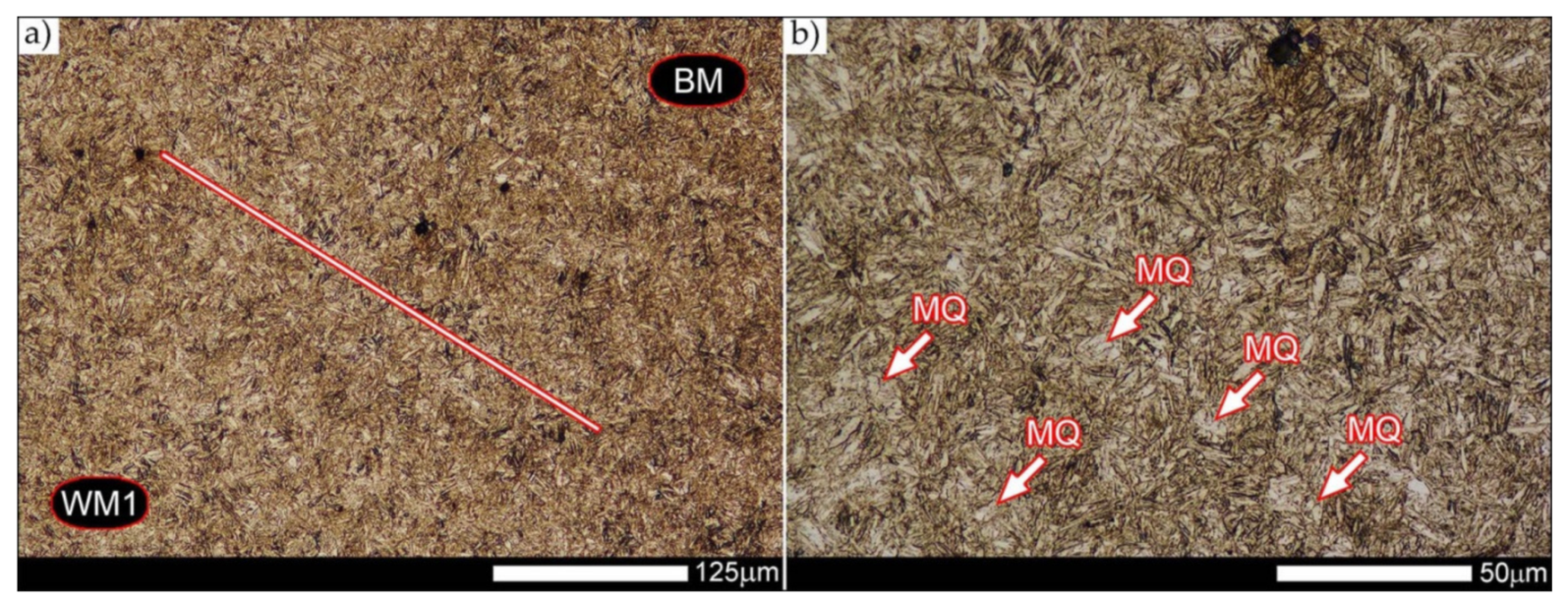
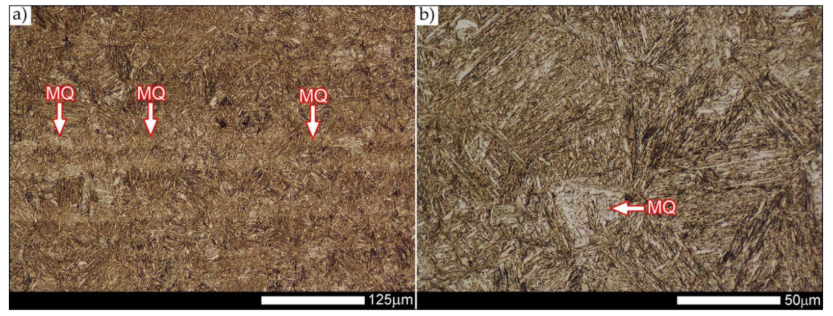
Referring to the structural properties recorded on individual FL1 and FL2 fusion lines of the welded joint under consideration (
Figure 33 and
Figure 34), it should be noted that the comprehensive heat treatment procedures carried out led to an almost complete homogenization of the structure in these zones. As a result, the structure of fine-lathed, medium-carbon tempering martensite with few zones of quenching martensite was obtained (marking MQ in
Figure 33). It is also worth adding that there are relatively few areas of the martensite structure with block morphology in this case, which indicates a similar percentage of carbon in these areas.
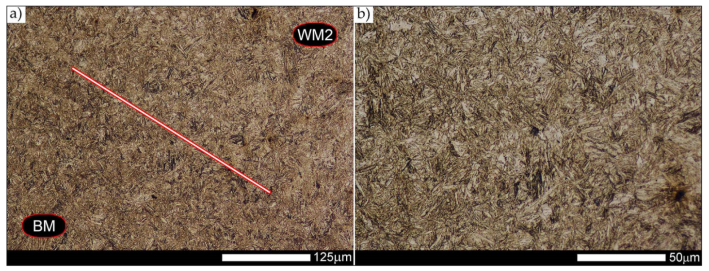
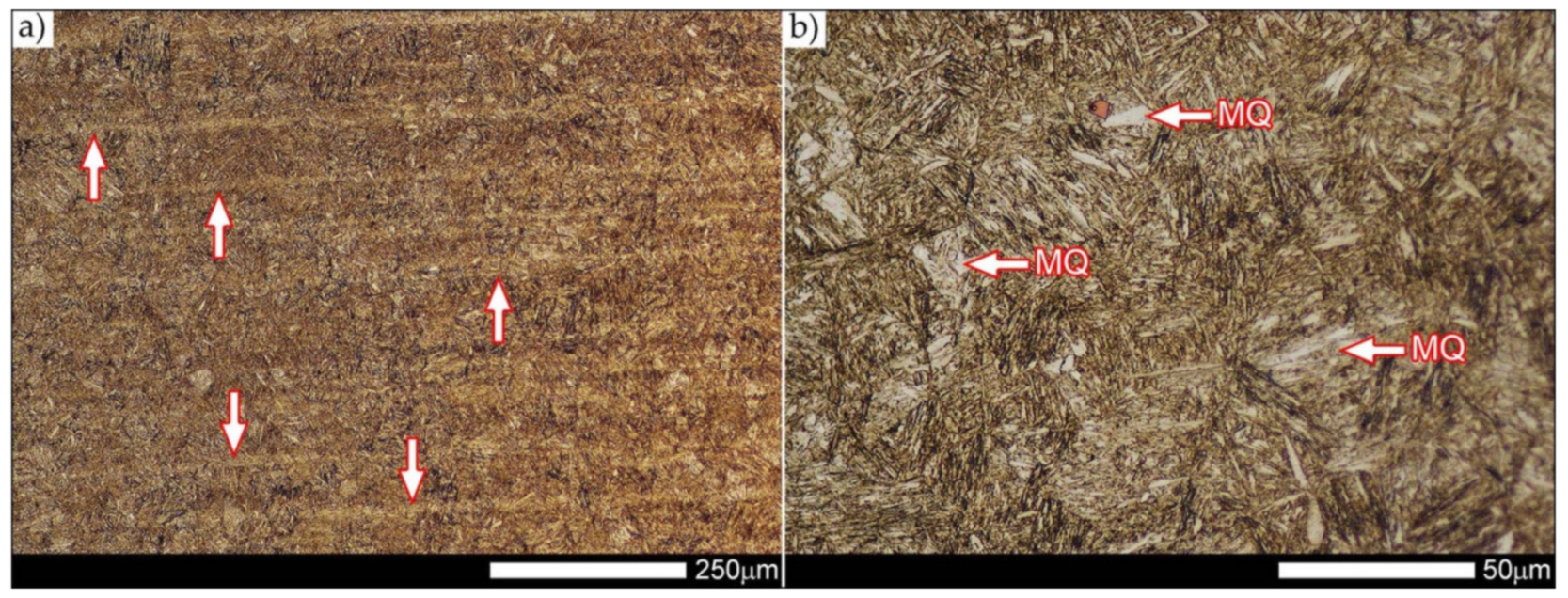
Micro-structure of the heat-affected zone and the base material, marked respectively as HAZ and BM in
Figure 29, showed no significant differences as a result of the thermal treatments performed. In both cases, a similar structure is observed, consisting of tempering martensite with numerous bands of unremoved martensite structure (MQ designation in
Figure 35 and
Figure 36). The presence of these bands is a direct result of producing Hardox 600 sheets technology—thermomechanical rolling—which were not “removed” during the applied post-welding thermal treatments. It is also worth mentioning here that the structural properties of the zones in question, especially the BM zone shown in
Figure 36, are very similar to the properties of the base material supplied directly from the steelworks, shown in
Figure 12.
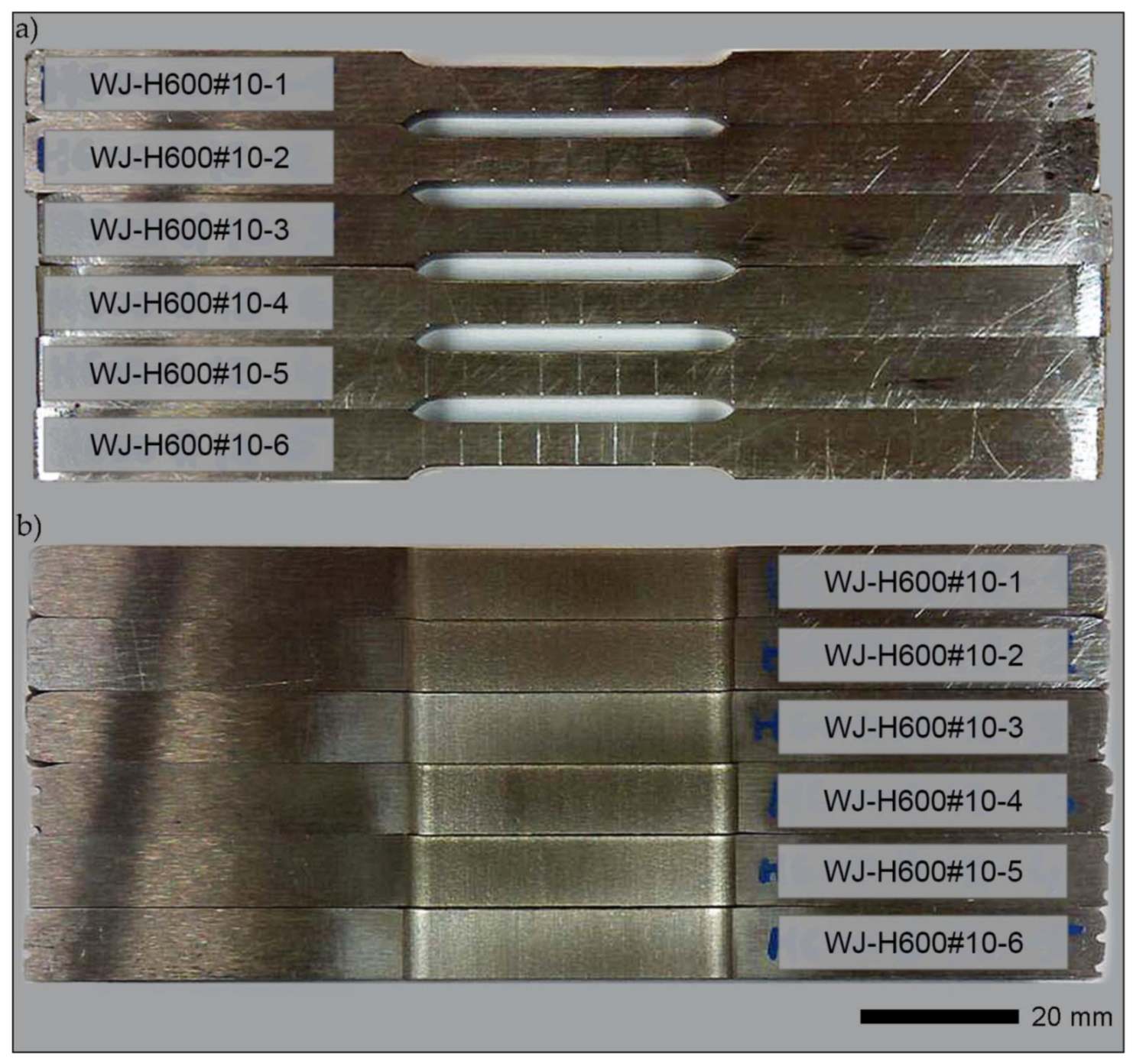
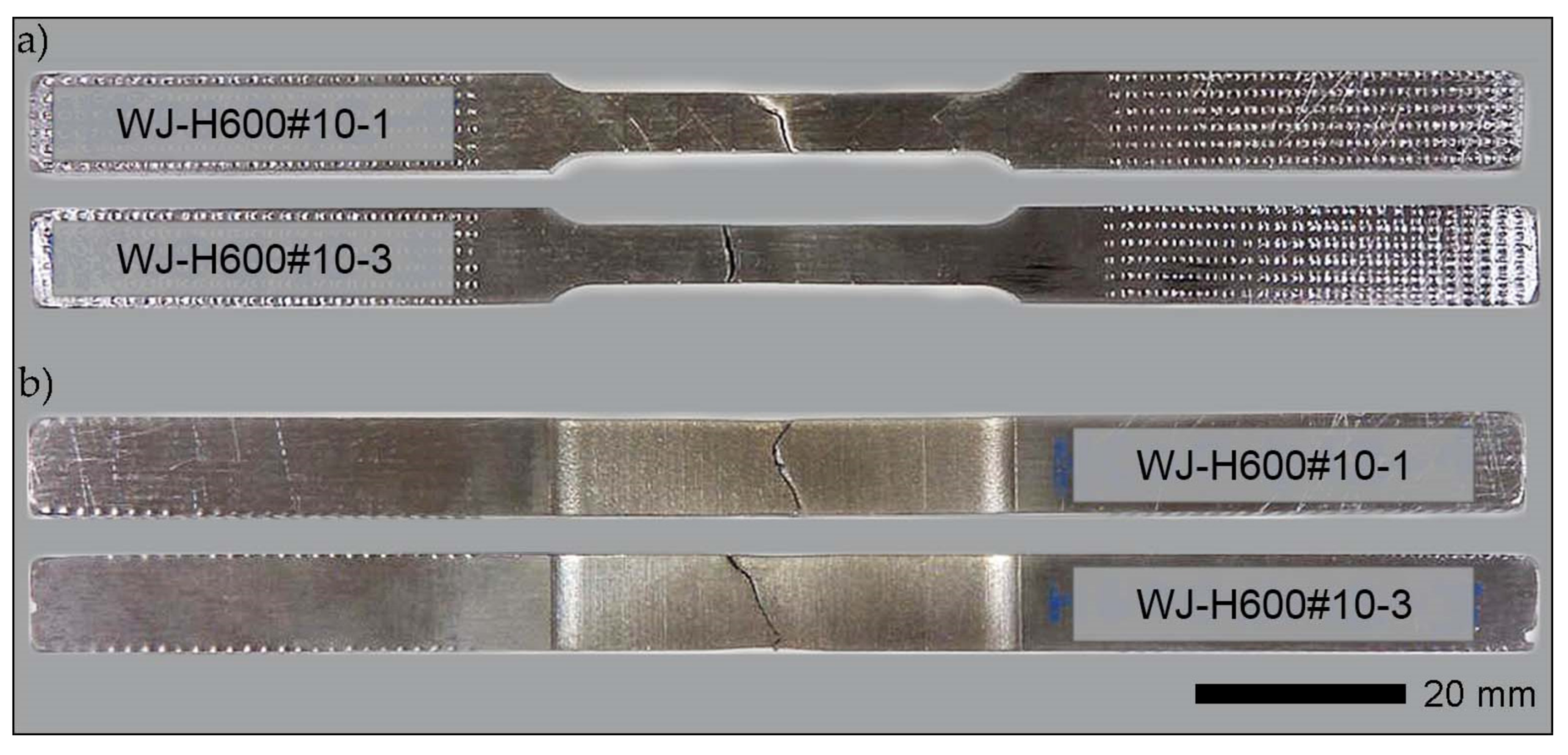
3.3. Results of the Fractographic Analysis
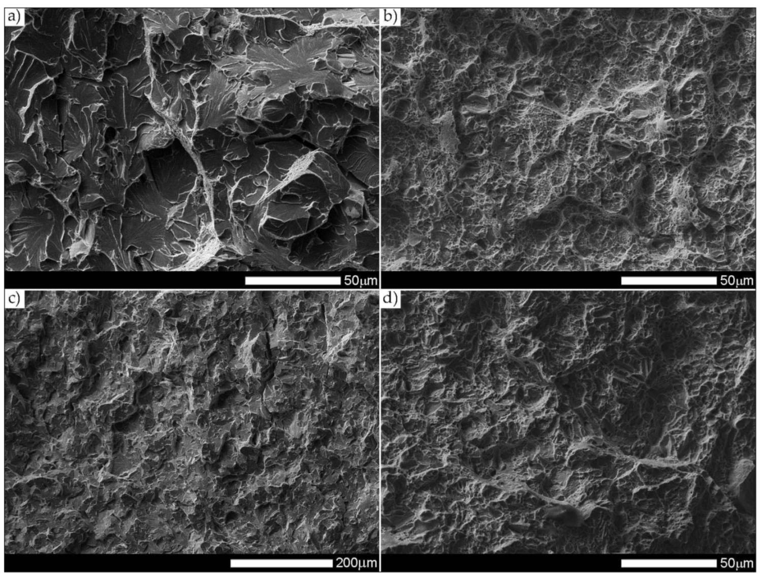
Figure 37 presents macroscopic images of the fracture surfaces of welded joints representative samples, subjected to impact toughness tests at +20 °C and −40 °C. As a result of the fractographic analysis, very significant differences in the overall structure of fractures between the analyzed series of samples can be identified. Regardless of the test temperature, the fractures of welded joints samples as delivered (immediately after welding) do not show a significant share of plastic side zones. At the temperature of +20 °C, the share of the plastic zone occurring only locally does not exceed 2% of the total fracture area (frame D1 in
Figure 37). In the case of samples subjected to the impact test at −40 °C, these shares do not exceed 1% (frame D3 in
Figure 37); therefore, their presence can be described as marginal. The above-described state of affairs proves the expenditure of very little energy during the formation of fractures, which also confirms the obtained very low impact indexes of the welded joint in the delivered condition. In the case of fractures of welded joint samples subjected to complex heat treatment, in the entire temperature range of impact tests, they show significant shares of plastic side zones. At a temperature of +20 °C, these shares can be estimated at 20% (frame D2 in
Figure 37) and about 12% for the Charpy test carried out at 40 °C (frame D4 in
Figure 37). The clear presence of relatively wide plastic side zones on the fracture surfaces of heat-treated samples indicates formation of fractures over a longer period of time, with the simultaneous expenditure of considerable energy. The above statement seems to be justified by the values of impact indices obtained (
Table 6). In addition, the macroscopic analysis performed showed that the fractures of the samples in the delivered condition are characterized by a different topography, resulting from the presence of fractures almost on the entire surface (except for the fracture zones marked with frames C1 and C3 in
Figure 37), a coarse-grained structure on the fusion line. On the other hand, of the welded joint surfaces of the fractures subjected to additional heat treatment can be considered fine-grained, homogeneous, characterized by roughness, running in the direction of crystallization during welding. In order to identify the structure of the fracture surfaces individual zones in question, all samples were subjected to further examination using SEM electron microscopy.
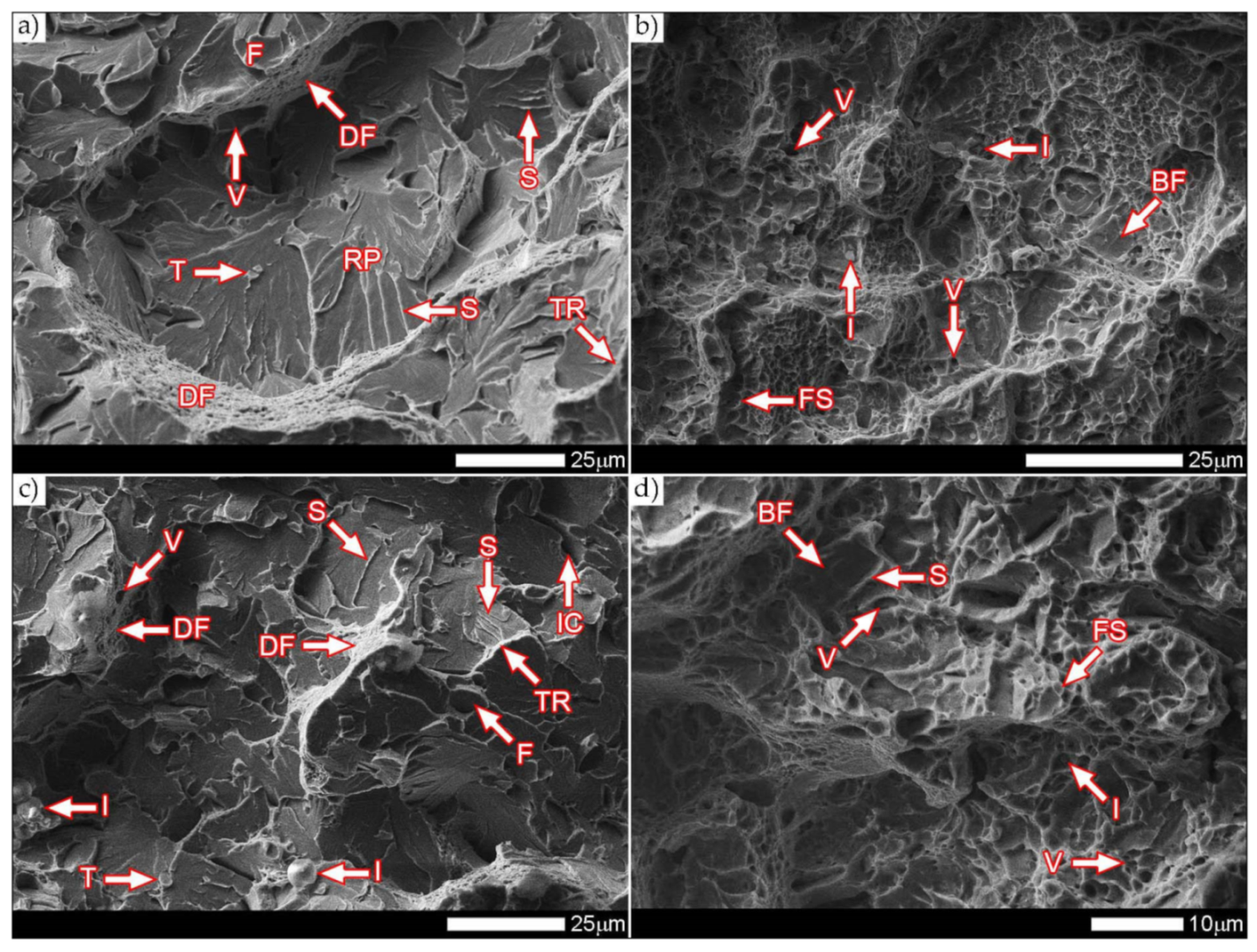
Figure 38 and
Figure 39 present images of the fracture surfaces in the area under the mechanical notch—frame A in
Figure 37. As a result of the fractographic studies, it can be concluded that, in terms of side fractures of the welded joint in the delivered condition (not heat-treated), there are brittle transcrystalline fractures. This statement applies to both samples after the Charpy test at −40 °C and at ambient temperature (
Figure 38a,c and
Figure 39a,c). Fractures of this type arise as a result of fracture mechanism occurring along specific crystallographic planes—cleavage planes—depending on the type of material (structure) and loading conditions. In metallic materials with a spatially centered regular lattice, these are usually the {100} [
29] planes in which the plastic deformation is the smallest. It is worth noting that the discussed type of fracture is most often initiated by various types of blocking mechanisms (e.g., defects in the crystallographic structure), but it can also nucleate at the grain boundaries. Therefore, a cleavable fracture often exhibits a very varied surface topography with many distinctive features.
Figure 39 shows selected fractures of the welded joint in the delivered condition. There are sets of numerous steps (S) located on large (in terms of size) facets (F). These steps create a characteristic “river pattern” (RP), often cutting across whole grains. The presence of steps proves that the fracture course did not occur only in one crystallographic plane but repeatedly passed to the adjacent planes by cutting or secondary fracture of the dividing walls. The steps are seen where the front of the fracture hits the helical dislocation, while their height is related to the amount of energy absorbed during fracture—reduction of the brittleness threshold [
30]. Steps with a fairly flat course, characterized by a very extensive system of “river pattern”, dominate on the surfaces of the studied fractures. These features indicate a small amount of energy absorbed during the crack formation, which is also confirmed by the impact toughness indexes obtained (
Table 6, No. 1). In the context of the results of structural studies presented in this manuscript, it is also worth referring to the observed correlation between the fracture morphology of unheated samples and their micro-structural features. In iron alloys with a structure different from that of martensite or lower bainite, the course of splitting fracture is determined only by a grain size of the former austenite [
29,
30]. Thus, it does not depend on the type and number of secondary phases and mainly depends on the crystallographic orientation of individual grains or micro-structure blocks. This is due to the fact that the development of cleavage fracture is inhibited at the grain boundaries, which is reflected in the formation of the set of the steps described above. The precipitation of foreign phases inside the grains cause a temporary slowdown (stop) of the fracture process, initiating new systems of “river pattern”. On the other hand, the precipitation of foreign phases at the grain boundaries is attributed to the occurrence of inter-crystalline cracks (IC designation in
Figure 39a,c). Segregation of the chemical composition may have a similar effect on the nature of fracture. In addition to the features discussed above, the so-called “tongues” (T) are also noted in the fracture in question. According to [
29], their presence is related to a local plastic deformation during fracture at the boundaries of micro-structure blocks as a result of encountering a twin boundary formed in front of the fracture front. Therefore, as a result of this process, the fracture front “flows around” (bypasses) these zones without going beyond the original plane of its course—in steels with A3 lattice—the {112} plane. Therefore, it can be concluded that the observed morphological features of the welded joint fractures in the delivered condition confirm the identification of phases and structure components (ferrite, sorbite, troostite, upper bainite and martensite regions).
In the case of samples of a welded joint subjected to heat treatment, in the area under the mechanical notch—frames A2 and A4 in
Figure 37—at both impact test temperatures, the nature of the fractures can be described as mixed (plastic–brittle or quasi-cleavable)—
Figure 38b,d and
Figure 39b,d. On the surfaces of the fractures, a dimple rapture of various sizes of voids dominates. Fractures of this type are formed by coalescence of micro-voids —already existing in the material or formed and grown during loading—up to the point of plastic decohesion. It is observed that micro-voids may form at the boundaries of non-metallic inclusions or secondary phase precipitation with the material matrix at the boundaries of these phases or as a result of mechanical destruction of inclusions, which locally lead to stress accumulation [
29,
31]. In most cases, at the bottom of the cavities (voids), both complete and damaged foreign phases are observed, as well as cavities after their removal. According to the discussed mechanism of dimple rapture formation, it seems logical to say that the size of the voids depends on the type, shape, number and distribution of inclusions facilitating the nucleation of micro-voids, as well as on the grain size, structure and plastic properties of the material. It can also be concluded from [
31] that the inhomogeneous distribution of inclusions as well as nucleation and growth of isolated micro-areas (micro-voids) during the initial stage of loading the sample lead to the formation of a fracture with a different size and arrangement of voids. In the case where the nucleation of the micro-voids takes place at the grain boundaries of the material’s micro-structure, the resulting fracture will be inter-crystalline.
It is also worth noting that, in metals of high chemical purity or metal alloys subjected only to supersaturation treatments (not aged, not tempered), characterized by the absence or a small number of secondary phases undissolved in solid solution, the presence of deep voids can only occasionally be observed. In such a case, the fracture structure is usually dominated by shallow recesses growing in lateral directions. From the point of view of a loading method, it is also possible to distinguish between even voids—uniaxial tension—and elongated voids with a parabolic scale-shaped contour, which are caused by shear or unequal tension. In such a case, formation of the characteristic “fish scale” structure may take place without the participation of foreign phase inclusions [
29]. Additionally, depending on shapes and types of the discussed void structure, the following types of fractures can be distinguished: normal plastic fracture (uniform voids), when the direction of stress is approximately normal to the scrap surface and the course of crack development is relatively slow, sheer plastic fracture (elongated voids with a parabolic contour) and a plastic fracture by tear, characterized by elongated voids with a parabolic end, facing the direction of the fracture development [
29,
31]. Therefore, the presence of the cited “fish scale” structure may result from different nucleation rates and crack development in individual fracture zones.
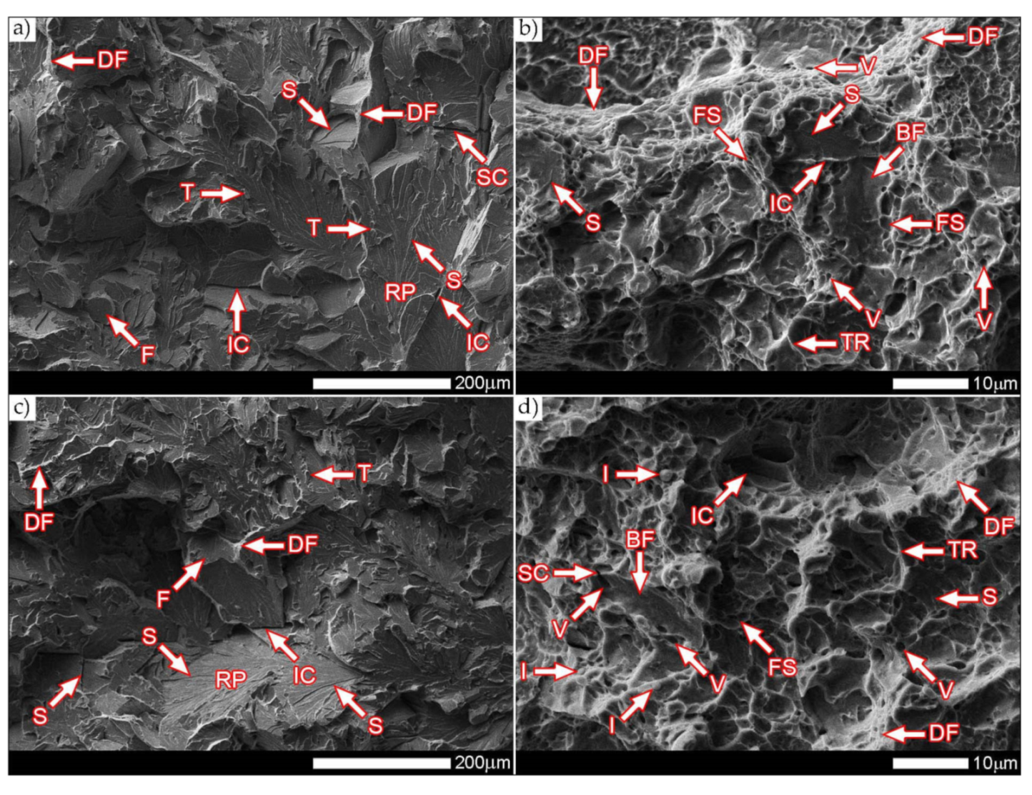
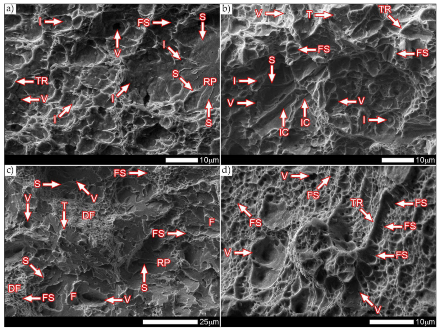
Figure 39b,d show the characteristic fracture zones of the analyzed heat-treated samples. The fractures obtained at both ambient and low temperature are characterized by the presence of voids of very different sizes. The discussed feature is particularly visible in the fracture zones with high plastic deformation (DF), where the presence of extremely small voids (V) is observed. The remaining areas are dominated by larger, shallow voids in which no phase precipitation is observed. Such a situation results directly from the state of heat treatment, which, in the final stage, included tempering operation at a fairly low temperature (100 °C), i.e., much below the temperature favorable to the precipitation processes. In some areas of the revealed fracture surfaces—especially at −40 °C—single non-metallic inclusions (I) are visible, which are fine slags formed directly in the welding process, most likely resulting from the presence of corrosion products on the ridges of the welded sheet. On the fracture surfaces, one can also observe a characteristic “fish scale” structure (FS) approximately running in the direction of the crack development (especially at ambient temperature). This is confirmed by the fact that the fracture process is initiated by plastic deformation within the voids, while the fracture itself takes place similarly to brittle fracture by cutting the walls separating them. In addition, the presence of the so-called “tear ridges” (TR) that indicate the presence of a quasi-fracture. Such a fracture is created by joining many local fractures, usually formed on the same crystallographic plane [
29], resulting in material’s decohesion, preceded by a strong plastic deformation. The presence of steps can also be indicated on the considered fracture surfaces—in brittle zones (BF). Nevertheless, their course is rather flat, without formation of the characteristic structure of “river pattern”, so it can be concluded that their contribution to energy absorption during destruction was marginal.
Figure 40 and
Figure 41 show images of the fracture surfaces in the central zone of the impact specimens—frame B in
Figure 37. The fractures of the samples as delivered, for both test temperatures, are cleavable fractures with small areas of plastic fractures (
Figure 40a,c and
Figure 41a,c). The presence of plastic zones is particularly observed on the sample tested at +20 °C. As a result of the fractographic analysis, it was shown that it is characterized by a very extensive structure, with various features of the surface topography—
Figure 41a. There are numerous fractures in a form of deep craters, and the bottom of which is dominated by a transcrystalline fracture with rather deep steps (S), forming the characteristic of “river pattern” (RP). This proves the expense of considerable energy during fracture and the course of the fracture front along many crystallographic planes, orientation of which, in this case, depended on the grain size of the former austenite. On the other hand, formation of a fairly extensive system of “river pattern” most likely results from the inhibition of a fracture front due to the presence of foreign phases, separated inside grains or micro-structure blocks. The same can be said for the so-called “tongues” (T) and “tear ridges” (TR). It is worth noting that the simultaneous presence of steps, tongues and tear ridges at the fracture allows us to characterize the fracture as quasi-cleavable [
29]. It is also worth noting clear presence of ductile fractures’ zones (DF) on the side walls of the formed craters. These zones are created by a characteristic dimple rapture, occurring in planes approximately consistent with the action of main stress. The presence of large voids (V), with a distinct elliptical contour, allows us to state that the decohesion of the sample material was preceded by a large plastic deformation and the coalescence of micro-voids occurring in the zones of clearly fragmented micro-structure. The fracture characteristics described above indicate the formation of a fracture under conditions of complex stress.
In the case of samples’ fractures subjected to heat treatment after welding, taken from the central zone—frames B2 and B4 in
Figure 37, it can be concluded that they show similar features of a mixed fracture, i.e., quasi-cleavage with many plastic areas. This statement applies to both impact test temperatures (
Figure 40b,d and
Figure 41b,d). In both cases, the plastic zones form transcrystalline fractures with a dimple structure. In the case of the fracture obtained at ambient temperature, small-sized voids (V) with relatively regular shapes dominate. Additionally, clearly visible “fish scale” structure (FS) running approximately in the direction normal to the action of the main stress (in the direction of fracture) may indicate a failure mechanism due to unequal tension and shear. Only sporadic presence of non-metallic inclusions (I), mainly located inside larger voids and at the boundaries of the micro-structure blocks, indicates that the initiation of micropore formation took place without the participation of foreign phase inclusions. Lowering the impact test temperature to −40 °C resulted in a clear reduction in the fracture surface of the analyzed sample in the proportion of plastic zones (
Figure 41d) dominated by the presence of voids (V) of various sizes, largely characterized by a parabolic outline.
In larger voids, as in the case of the sample tested at ambient temperature, the presence of non-metallic inclusions (I) is observed sporadically. On the fracture surface, the “fish scale” (FS) structure feature is also observed, occurring mainly in the zone of finer grain structure. Its volume share in relation to positive test temperature is much smaller, which indicates the course of fracture in a shorter time. With regard to both fractures of the heat-treated samples, it is also worth pointing out that the cleavage zones of their fractures do not show distinct features of the structure in the form of steps, forming the “river” pattern. The steps (S) present, rather, run on the boundaries of micro-structure blocks, and in special cases they can also be classified as tear ridges (TR). This situation indicates that the absorption of energy during fracture in the central part of the samples took place mainly through nucleation and coalescence of micro-voids.
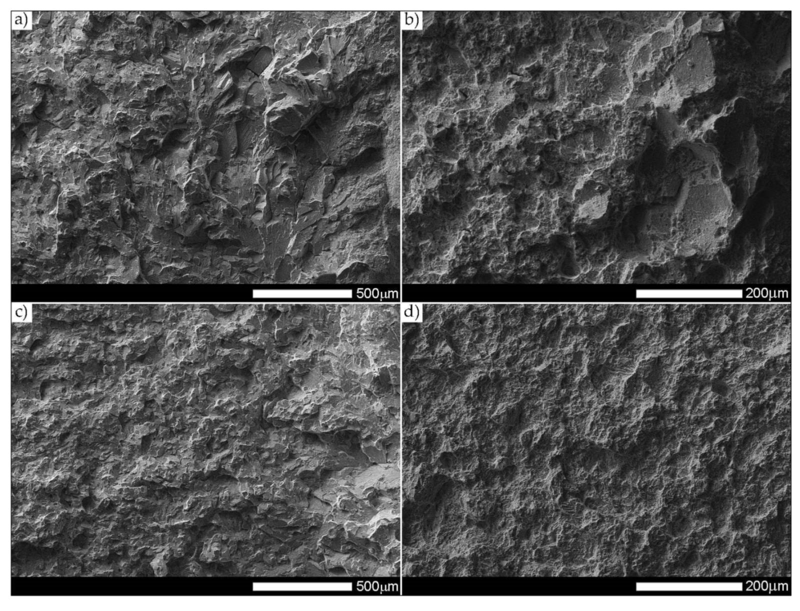
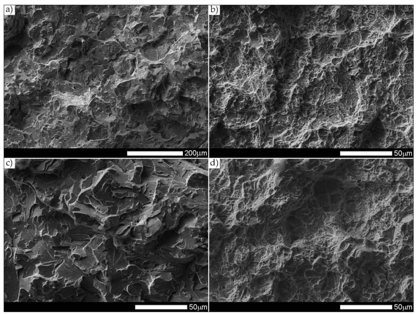
The fracture zones of the tested samples—frames “C” in
Figure 37—are shown in
Figure 42 and
Figure 43. The fractures of the samples in the delivered condition, tested at ambient temperature, can be defined as mixed fractures (plastic-brittle) with significant shares of plastic zones (
Figure 42a and
Figure 43a). Plastic zones are characterized by a void structure, with a fairly even arrangement and size of the voids, overlapping in the form of “scales” (
Figure 42a). The features of the fracture structure, clearly visible in
Figure 42a, indicate that the plastic zone of the fracture was created both by equiaxial tension and by the so-called tearing, resulting in the formation of voids with a parabolic contour facing the direction of the fracture development. It can also be indicated that the sources of micro-voids formation, which, as a result, of coalescence formed voids of larger sizes, were numerous inclusions of foreign phases (I). The presence of inclusions is recorded both at the bottom and on the side walls formed by the crater voids. The cleavage zones of the fracture in question show the presence of numerous steps (S), converging radially to the axis of the crater, creating at the same time a characteristic “river pattern” (RP). The height of the steps can be described as quite varied, in places flat and slightly outlined, and locally quite high—merging with tear ridges (TR). This state of affairs indicates that, in the fracture zone of the sample, considerable energy was expended during the fracture formation. It is worth emphasizing that the above statement can be applied both to plastic and quasi-cleavage zones of the fracture. On the other hand, the fracture of the same sample, tested at −40 °C, shows a quite similar structure to the fracture discussed earlier, but it shows much smaller shares of plastic zones (
Figure 42c and
Figure 43c).
Thus, it is dominated by a cleavage fracture with a relatively small number of rather high steps (S). The system of so-called “rivers” (RP) is observed rather sporadically. This proves the course of the fracture in a relatively short time, which significantly hindered the formation of twin boundaries at the front of the fracture. It is also worth pointing to the presence of characteristic, deep voids on the fracture surface, formed by the coalescence of micro-voids (V), clearly visible at their bottom. On the other hand, no significant participation of foreign phase inclusions in the fracture initiation process is observed. Therefore, it can be assumed that the fracture mechanism in the fracture in question takes place along specific cleavage planes, resulting from the granular or block micro-structure of the material. The sample zones with a fragmented micro-structure are characterized by the presence of transcrystalline ductile fracture (DF) with a characteristic structure and arrangement of voids in the form of overlapping “scales” (FS). This indicates that the fracture process was preceded by a large plastic deformation. Due to the relatively small share of plastic fracture on the analyzed fracture surface, it can be stated that the cleavage fracture mechanism had a decisive influence on the value of fracturing work of the welded joint in the delivered condition, subjected to impact tests at reduced temperature.
The fractures of the heat-treated samples, in the entire temperature range of the impact toughness test, in the fracture zone are characterized by a similar void structure (
Figure 42b,d and
Figure 43b,d). In both cases, it can be concluded that the surface of the samples is dominated by a plastic fracture with a fairly uniform arrangement of voids. The formation of the observed structure begins in the micro-voids (V), at the bottom of which the precipitation of foreign phases (I) is observed only sporadically. Due to faster fracture process, at the fracture of the sample tested at negative temperature (
Figure 43c), the characteristic “fish scale” (FS) structure appears to a greater extent, running approximately in the direction of fracture. The parabolic outline of the scale structure indicates uneven loading during fracture formation, resulting from unequal tension or so-called tears. With regard to the sample tested at negative temperature, it is also possible to state the presence of a plastic fracture resulting from the action of shear forces [
29]. This is evidenced by the presence of long strands of scale structure (FS), often ended (or separated) by large voids. The presence of micro-voids in the strands of the scale structure is observed, and the interface between the strands may be tear ridges (TR). However, such a situation is not observed in the fracture at ambient temperature (
Figure 43b), in which the scale structure is observed to a much lesser extent. In the surface of this fracture, no large number of deep, topographically developed voids is also observed. Shallow, very small, locally parabolic voids dominate. It is also possible to indicate the local occurrence of relatively larger areas of the cleavage fracture (without clear steps) but separated by inter-crystalline cracks (IC). Most likely, it results from the morphology of the martensitic structure obtained in the course of post-welding heat treatment, which was characterized by a relatively low variation in the crystallographic orientation of the formed blocks within the former austenite grains. The described type of structure, in low-alloy steels, may be characterized by a lower level of impact toughness, especially in the case of increased carbon content, in relation to the martensitic structure of high variability [
32].
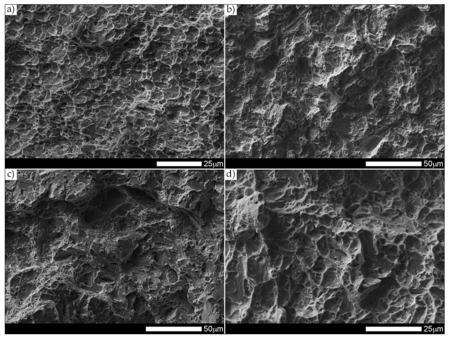
Figure 44 and
Figure 45 present images of the fracture surfaces of the tested samples, recorded in the lateral zones—the areas marked with “D” frames in
Figure 37. Within the same series of samples, i.e., in the delivered condition and heat-treated, the fractures share similar morphological features. Immediately after welding, for both test temperatures, the fractures of samples can be described as transcrystalline cleavable, with very small areas of plastic fractures—
Figure 44a,c and
Figure 45a,c. In both cases, numerous steps (S) of varying heights are present. In areas formed by blocks of similar micro-structure, steps have a flat course, creating a branched system of “river pattern” (RP). In other areas, quite high steps—indicating the expenditure of considerable energy during the fracture process–largely resemble so-called tear ridges (TR). In addition, the presence of “tongues” is observed, which, taking into account the features described above, allows the fracture to be classified as quasi-cleavage. It is also worth adding that at the fracture in ambient temperature (
Figure 44a and
Figure 45a), in selected cleavage zones, the development of void fractures, characteristic of a plastic fracture, is sporadically observed. It is especially noticeable at lower magnification in the form of characteristic facets deformed at the ridges—
Figure 44a. Additionally, in both impact test temperatures, the fractures show numerous extensive inter-crystalline cracks, the presence of which can be mainly explained by a very large diversity of micro-structure within the heat-affected zone. Observed structure of the samples’ fracture in the delivered condition proves that the formation of fractures took place well below the brittleness threshold of the material.
On the other hand, the fractures of the samples subjected to heat treatment (
Figure 44b,d and
Figure 45b,d) can be described as quasi-cleavable with very large areas of plastic fracture. This is evidenced by extensive ductile zones (DF), in which most of the characteristic void structure are observed, arranged in the form of “fish scales” (FS). Small, even voids (V) dominate, at the bottom of which there are very fine particles of inclusions (I).
The cleavage zones of the fractures in question, on the other hand, are characterized by high steps (S), places that are very difficult to distinguish from tear ridges (TR). In the fracture zones in question, the presence of “river” pattern is not observed. Few flat surfaces of these fractures locally show the presence of “tongues”, formed as a result of a twinning mechanism of micro-voids, located directly on the fracture front.


